EP3352642B1 - Fluid filtration, cleaning, and defogging device - Google Patents
Fluid filtration, cleaning, and defogging device Download PDFInfo
- Publication number
- EP3352642B1 EP3352642B1 EP16862890.7A EP16862890A EP3352642B1 EP 3352642 B1 EP3352642 B1 EP 3352642B1 EP 16862890 A EP16862890 A EP 16862890A EP 3352642 B1 EP3352642 B1 EP 3352642B1
- Authority
- EP
- European Patent Office
- Prior art keywords
- opening
- operable
- cleaning
- housing
- conduit
- Prior art date
- Legal status (The legal status is an assumption and is not a legal conclusion. Google has not performed a legal analysis and makes no representation as to the accuracy of the status listed.)
- Active
Links
Images



Classifications
-
- A—HUMAN NECESSITIES
- A61—MEDICAL OR VETERINARY SCIENCE; HYGIENE
- A61B—DIAGNOSIS; SURGERY; IDENTIFICATION
- A61B1/00—Instruments for performing medical examinations of the interior of cavities or tubes of the body by visual or photographical inspection, e.g. endoscopes; Illuminating arrangements therefor
- A61B1/12—Instruments for performing medical examinations of the interior of cavities or tubes of the body by visual or photographical inspection, e.g. endoscopes; Illuminating arrangements therefor with cooling or rinsing arrangements
- A61B1/121—Instruments for performing medical examinations of the interior of cavities or tubes of the body by visual or photographical inspection, e.g. endoscopes; Illuminating arrangements therefor with cooling or rinsing arrangements provided with means for cleaning post-use
- A61B1/123—Instruments for performing medical examinations of the interior of cavities or tubes of the body by visual or photographical inspection, e.g. endoscopes; Illuminating arrangements therefor with cooling or rinsing arrangements provided with means for cleaning post-use using washing machines
-
- A—HUMAN NECESSITIES
- A61—MEDICAL OR VETERINARY SCIENCE; HYGIENE
- A61B—DIAGNOSIS; SURGERY; IDENTIFICATION
- A61B1/00—Instruments for performing medical examinations of the interior of cavities or tubes of the body by visual or photographical inspection, e.g. endoscopes; Illuminating arrangements therefor
- A61B1/12—Instruments for performing medical examinations of the interior of cavities or tubes of the body by visual or photographical inspection, e.g. endoscopes; Illuminating arrangements therefor with cooling or rinsing arrangements
- A61B1/121—Instruments for performing medical examinations of the interior of cavities or tubes of the body by visual or photographical inspection, e.g. endoscopes; Illuminating arrangements therefor with cooling or rinsing arrangements provided with means for cleaning post-use
-
- A—HUMAN NECESSITIES
- A61—MEDICAL OR VETERINARY SCIENCE; HYGIENE
- A61B—DIAGNOSIS; SURGERY; IDENTIFICATION
- A61B1/00—Instruments for performing medical examinations of the interior of cavities or tubes of the body by visual or photographical inspection, e.g. endoscopes; Illuminating arrangements therefor
- A61B1/12—Instruments for performing medical examinations of the interior of cavities or tubes of the body by visual or photographical inspection, e.g. endoscopes; Illuminating arrangements therefor with cooling or rinsing arrangements
- A61B1/127—Instruments for performing medical examinations of the interior of cavities or tubes of the body by visual or photographical inspection, e.g. endoscopes; Illuminating arrangements therefor with cooling or rinsing arrangements with means for preventing fogging
-
- A—HUMAN NECESSITIES
- A61—MEDICAL OR VETERINARY SCIENCE; HYGIENE
- A61B—DIAGNOSIS; SURGERY; IDENTIFICATION
- A61B1/00—Instruments for performing medical examinations of the interior of cavities or tubes of the body by visual or photographical inspection, e.g. endoscopes; Illuminating arrangements therefor
- A61B1/12—Instruments for performing medical examinations of the interior of cavities or tubes of the body by visual or photographical inspection, e.g. endoscopes; Illuminating arrangements therefor with cooling or rinsing arrangements
- A61B1/128—Instruments for performing medical examinations of the interior of cavities or tubes of the body by visual or photographical inspection, e.g. endoscopes; Illuminating arrangements therefor with cooling or rinsing arrangements provided with means for regulating temperature
-
- A—HUMAN NECESSITIES
- A61—MEDICAL OR VETERINARY SCIENCE; HYGIENE
- A61L—METHODS OR APPARATUS FOR STERILISING MATERIALS OR OBJECTS IN GENERAL; DISINFECTION, STERILISATION OR DEODORISATION OF AIR; CHEMICAL ASPECTS OF BANDAGES, DRESSINGS, ABSORBENT PADS OR SURGICAL ARTICLES; MATERIALS FOR BANDAGES, DRESSINGS, ABSORBENT PADS OR SURGICAL ARTICLES
- A61L2103/00—Materials or objects being the target of disinfection or sterilisation
- A61L2103/15—Laboratory, medical or dentistry appliances, e.g. catheters or sharps
-
- A—HUMAN NECESSITIES
- A61—MEDICAL OR VETERINARY SCIENCE; HYGIENE
- A61L—METHODS OR APPARATUS FOR STERILISING MATERIALS OR OBJECTS IN GENERAL; DISINFECTION, STERILISATION OR DEODORISATION OF AIR; CHEMICAL ASPECTS OF BANDAGES, DRESSINGS, ABSORBENT PADS OR SURGICAL ARTICLES; MATERIALS FOR BANDAGES, DRESSINGS, ABSORBENT PADS OR SURGICAL ARTICLES
- A61L2202/00—Aspects relating to methods or apparatus for disinfecting or sterilising materials or objects
- A61L2202/10—Apparatus features
- A61L2202/12—Apparatus for isolating biocidal substances from the environment
- A61L2202/122—Chambers for sterilisation
Definitions
- the present disclosure provides a method and apparatus for aiding medical procedures. More particularly, embodiments of the present disclosure provide a filtration, cleaning, and defogging device for aiding surgical or medical procedures.
- a laparoscope or endoscope is used in conjunction with a camera system for visualization during surgical procedures.
- the scope is introduced from ambient room temperature into a cavity at body temperature, the rapid change causes the lens to fog.
- surgical tools such as an electrosurgical device deliver energy, creating heat, and vaporizes the intracellular fluid, which increases the pressure inside the cell and eventually causes the cell membrane to burst.
- a plume of smoke containing mostly water vapor is created, along with the aeration of cellular debris.
- Patent documents US2008/161646 A1 and WO 2015/171771 A1 are example of devices developed to overcome such problems.
- An exemplary embodiment of the present disclosure provides an apparatus for filtration, cleaning, and defogging.
- the apparatus includes a first housing comprising a cleaning element maintained within the first housing, the cleaning element a cleaning fluid operable to remove debris from an object, the cleaning element occluded within the housing by at least one frangible disc.
- the apparatus further includes a second housing comprising a filtration conduit through a passage within the second housing, the second housing operable to be removeably coupled to the first housing,
- the filtration conduit comprising a filter and a liquid trap, the filtration conduit operably coupled to a flow selector operable to regulate a flow of fluid through the filtration conduit.
- a corresponding method for aiding medical procedures is also disclosed.
- the terms “horizontal.”, “vertical”, “left”, “right”, “up” and “down”, as well as adjectival and adverbial derivatives thereof, simply refer to the orientation of the illustrated structure as the particular drawing figure faces the reader.
- the terms “inwardly” and “outwardly” generally refer to the orientation of a surface relative to its axis of elongation, or of rotation, as appropriate.
- Embodiments of the present disclosure provide a device operable to interact with medical or surgical devices or tools (e.g., a scope for laparoscopic or endoscopic procedures, trocars, scalpels, and the like) such that the medical or surgical tools can be cleaned and/or defogged to aid in medical or surgical procedures.
- medical or surgical devices or tools e.g., a scope for laparoscopic or endoscopic procedures, trocars, scalpels, and the like
- Embodiments of the present disclosure also provide a device operable to filter a flow of fluid from a patient's body (e.g., smoke or vapor from a patient's body cavity produced during surgery).
- Embodiments further provide a white balance for improved video/pictures from a scope during surgical or medical procedures.
- Embodiments of surgical or medical procedures include laparoscopy, endoscopy, arthroscopy, bronchoscopy, colonoscopy, cystoscopy, enteroscopy, hysteroscopy, laryngoscopy, mediastinoscopy, ureteroscopy, and other procedures involving a scope in a body cavity.
- the device 10 includes a housing 13.
- the housing 13 has a first opening 16 for receiving a medical/surgical scope in a generally vertically oriented position and a second opening 19 for receiving a scope in a generally horizontally oriented position.
- An illumination element 102, 104 or a plurality of illumination devices, such as light emitting diodes, may be disposed around the openings 16, 19 to indicate a location of openings 16 and 19 on housing 13 to facilitate insertion of the surgical scopes and other medical devices in darker environments.
- Illumination devices 102, 104 may also be used to indicate when the device 10 is ready for use.
- Illumination devices 102, 104 may also be used to indicate the flow setting for the filtration portion of the device 10.
- the openings 16, 19 may be sealed by a frangible disc 20, 21 made of an elastomeric material or the like.
- the frangible discs 20, 21 are provided to seal openings 16, 19 along with a cleaning solution in the device prior to use.
- the housing 13 is closed and sealed to protect the internal components from exposure to outside elements.
- a microfiber wipe 22 may be mounted to the exterior of the housing 13 such that a scope may be brought into contact with the wipe 22 to remove debris. This embodiment utilizes separate compartments to clean, warm and white balance a scope.
- the first embodiment of the device 10 also provides for fluid filtration.
- a conduit or tube 25 provides for an input passageway to a filter system disposed in the housing 13.
- the conduit 25 may be provided with a luer lock (not shown) that attaches to a conduit or trocar leading to a pressurized surgical site such as a laparascopy with a pneumoperitoneum.
- the conduit 25 leads to a liquid trap 29.
- Embodiments of liquid trap 29 are operable to remove liquid such as condensed water vapor from a gas.
- Carbon or other odor removing media and particulate filters 27 are disposed inside the housing 13. Embodiments of filters 27 allow a flow of air or fluid through conduit 25 while removing extraneous materials or debris from the air or fluid.
- a flow selector 30 is disposed on the exterior of the housing 13.
- a second conduit or tube 33 extending from the opposite end of the housing 13 may be disposed in fluid communication with either a vacuum system or with atmosphere. The system may be manually or automatically switched between connection to a vacuum source or venting to atmosphere.
- the flow selector 30 provides for adjustment of the flow through the filtration device without deflating the peritoneal cavity.
- the first embodiment of the device may be provided with a power source such as one or more batteries 35.
- the batteries 35 may be installed within housing 13 at a mid-portion of the device 10.
- the batteries 35 may be provided in a circuit for providing heat through electrical resistance in a printed circuit board (PCB).
- the circuit board may be designed to have multiple and separate heater sections built into the circuit.
- the circuit may be rigid or flexible.
- the device may be provided with an electronic control circuit to maintain PCB temperature of the heating circuit for warming the cleaning fluid.
- the heating element can be a dedicated component separate from the circuit board.
- the heating element may be flexible or ridged to allow for a bundle of wire to be around the port to provide a heater. Heating can be provided to one or both ports or openings 16, 19 and may have independent temperatures.
- FIG. 5 An alternate embodiment is shown in FIG. 5 .
- device 100 which includes a housing 103.
- the housing 103 has a first opening 106 for receiving a scope in a generally vertically oriented position, and a second opening 109 for receiving a scope in a generally horizontally oriented position.
- a plurality of illumination devices 105, 107 such as light emitting diodes, may disposed around the openings 106, 109 to facilitate insertion of the surgical scopes in darker environments.
- the openings 106, 109 may be sealed by a frangible disc 110, 111 made of an elastomeric material or the like.
- the frangible discs 110, 111 are provided to seal a cleaning solution in the device prior to use.
- the housing 103 is closed and sealed to protect the internal components from exposure to outside elements.
- a microfiber wipe 112 may be mounted to the exterior of the housing 103 such that a scope may be brought into contact with the wipe to remove debris and/or extraneous material. This embodiment utilizes separate compartments to clean, warm and white balance a scope.
- the device 100 also provides for fluid filtration.
- a conduit or tube 125 provides for an input passageway to a filter system disposed in the housing 103.
- the conduit 125 may be provided with a luer lock (not shown) that attaches to a conduit or trocar leading to a pressurized surgical site such as a laparascopy with a pneumoperitoneum.
- the conduit 125 leads to a liquid trap 129 operable to remove liquid from a gas.
- Carbon or other odor removing media and particulate filters 127 are disposed inside the housing 103.
- a flow selector 130 is disposed on the exterior of the housing 103. Embodiments of flow selector 130 are operable to regulate and change upon user input a flow of gas or fluid through conduit 25.
- a conduit or tube 133 extending from the opposite end of the housing 103 may be disposed in fluid communication with either a vacuum system or with atmosphere.
- the system may be manually or automatically switched between connection to a vacuum source or venting to atmosphere.
- the housing 103 also includes a window 138 for viewing levels of liquid trapped in liquid trap 129.
- the flow selector 130 provides for adjustment of the flow through the filtration device without deflating the peritoneal cavity.
- the filter(s) 127 are disposed in alignment with the flow selector and may be positioned between the flow selector 130 and the liquid trap chamber 129.
- a cavity 145 may be formed to receive the scope vertically through the first opening 106.
- a cleaning material may be disposed at the bottom of the cavity. The cleaning material may comprise a sponge or other soft, porous material for receiving and holding a cleaning solution.
- Adjacent to the cavity 145, a horizontal bed 148 provides for support of a horizontally disposed scope that is inserted through the second opening 109.
- a power source such as one or more batteries 155 may be mounted in a middle portion of the assembly.
- the power source may be used to provide power to a heater for the warming fluid for the scope.
- the batteries 155 may be provided in a circuit for providing heat through electrical resistance in a printed circuit board 156.
- the circuit board 156 may be designed to have multiple and separate heater sections built into the circuit.
- the circuit board 156 may be rigid or flexible.
- the device may be provided with an electronic control circuit to maintain printed circuit board (PCB) 156 temperature of the heating circuit for warming the cleaning fluid maintained within cavity 145 and/or horizontal bed 148.
- PCB printed circuit board
- device 100 can include a heating element (e.g., a resistance heating element) that is a dedicated component separate from the circuit board operable to provide heat to the cleaning fluid maintained within the cavity 145 and/or horizontal bed 148.
- the heating element may be flexible or ridged to allow for a bundle of wire to be around the port to provide a heater. Heating can also be provided to one or both ports and may have independent temperatures.
- Embodiments of circuit board 156 and/or a heating element are operable to heat or warm the cleaning fluid maintained within the cavity 145 and/or horizontal bed 148 such that there is not a substantial temperature change between the heated cleaning fluid and an interior of a body cavity.
- the horizontally disposed portion of the cleaning device may contain a sponge or pair of sponges or a cleaning material 160 that is split to provide a channel for sliding the scope through the cleaning material.
- the two sponges 160 are configured to accept and to warm scopes 180, 185 (shown in FIG. 8 ) of all sizes.
- a V-shaped white reference material 165 may be disposed at the end of the cavity 148.
- the white balance reference material 165 is constructed of a non-porous material such as silicone.
- the white balance reference material 165 does not hold any liquid or cleaning solution and is arranged to provide a white balance for providing a reference color for optimizing the camera.
- the white balance reference material 165 is V-shaped so that scopes having different diameters may be inserted through the cleaning material 160 and into contact with the white balance reference material 165.
- FIG. 8 depicts a side view of the device 100 with a first scope 180 being warmed via the first opening 106 and a second scope 185 being cleaned and white balanced via the second opening 109.
- FIGS. 9-12 illustrated is an alternative embodiment of the fluid filtration and cleaning and defogging device 900.
- the device 900 as shown in FIGS. 9-12 is similar to the device illustrated in FIG. 1 and may be equipped with any of the parts, features, designs, and/or functionality as described hereinabove with reference to FIGS. 1-8 .
- Shown in FIGS. 9-12 is device 900 having a first opening 902 occluded by a frangible disc 904 operable to maintain a cleaning fluid.
- Device 900 also includes a second opening 906 occluded by a frangible disc 908 operable to maintain a cleaning material, a conduit 910 having a filter and liquid trap.
- FIG. 9-12 illustrated is an alternative embodiment of the fluid filtration and cleaning and defogging device 900.
- the device 900 as shown in FIGS. 9-12 is similar to the device illustrated in FIG. 1 and may be equipped with any of the parts, features, designs, and/or functionality as described hereinabove with reference
- second opening 906 with frangible disc 908 is shown located on a side face of device 900.
- Conduit 910 operable to be removeably coupled to a surgical site to pass gas or fluid from within a body cavity through conduit 910. It should be noted that in the embodiment illustrated in FIGS. 9-12 , the input and output of conduit 910 is located adjacent to one another. The flow of gas or fluid through conduit 910 can be operably regulated, changed or maintained by flow selector 912. Also shown is wipe 914 operable to remove extraneous material or debris from an opposing object, such as a medical or surgical tool.
- Embodiments of device 900 also include a heating element operable to heat the cleaning fluid and cleaning materials within device 900.
- the device housing as discussed with reference to FIG. 1 may be divided into two detachable and self-contained housings that can be either joined together into a single unit or used separately as distinct devices, as desired by the user.
- a first housing portion 916 may be dedicated to providing a laparoscopic warming device, while a second housing portion 918 may be dedicated to providing a peritoneal plume evaluator. While FIG.
- FIG 11 illustrates a first housing portion 916 attachable to a second housing portion 918 by a clip 920, it is anticipated that any appropriate coupling mechanism (e.g., snap, clasp, lock, rib, etc.) may be used. It is further anticipated that power and/or electrical signals may be passed between a first housing portion and a second housing portion via the coupling mechanism 920.
- any appropriate coupling mechanism e.g., snap, clasp, lock, rib, etc.
- FIG. 13 depicts a simplified block diagram in accordance with an exemplary method of aiding medical procedures.
- the process begins at block 1302 which states (a) providing a housing defining a first opening, a second opening, and an interior; (b) providing a first cleaning element maintained within the interior relative to the first opening, the first cleaning element comprising at least one cleaning agent operable to remove extraneous debris from an object; (c) providing a second cleaning element maintained with the interior relative to the second opening, the second cleaning element comprising at least one cleaning material and at least one white reference material, the at least one cleaning material operable to remove debris from an object; and (d) providing a conduit defining a passage from a first end of the housing to a second end of the housing, the conduit comprising at least one filter and at least one liquid trap, the conduit operable to allow a flow from the first end of the housing to the second end of the housing and to remove debris from the flow.
- block 1304 indicates wherein the housing further comprises a microfiber material fixedly
- Block 1306 relates to wherein the first opening is occluded by a first frangible disc operable to maintain the at least one cleaning agent within the first opening, and wherein the second opening is occluded by a second frangible disc.
- Block 1308 then states the conduit further comprising a flow selector operable to change a rate of flow of fluid through the conduit.
- Block 1310 goes on to state the first opening and the second opening each comprising at least one illumination device operable to at least partially indicate a location of the first opening and the second opening.
- Block 1312 then indicates the method further comprising providing a power source operably coupled to an electrical resistance element, the electrical resistance element operable to heat the interior.
- Block 1314 then relates wherein the electrical resistance element is a printed circuit board (PCB).
- Block 1316 states wherein the at least one cleaning agent is a porous material operable to receive and hold a cleaning solution.
- block 1318 indicates wherein the at least one cleaning material is a pair of sponges, and the at least one white reference material forms a V-shape operable to accept a scope.
- the logic diagram on FIG. 13 may be considered to illustrate the operation of a method, or a result of execution of computer program instructions stored in a computer-readable medium.
- the logic diagram of FIG. 13 may also be considered a specific manner in which components of a device are configured to cause that device to operate, whether such device is a medical or surgical device or some other related device, or one or more components thereof.
- Embodiments of the present invention may be provided with any of the aspects and features of the fluid filtration system as described in U.S. Patent Application No. 14/884,544, filed on October 15, 2015 , entitled “Fluid Filtration Device and System”.
- Embodiments of the device may also be provided with any of the aspects and features of the cleaning and defogging device as described in U.S. Patent Application No. 14/779, 986 filed May 6, 2015 , entitled "Laparascope and Endoscope Cleaning and Defogging Device”.
Landscapes
- Health & Medical Sciences (AREA)
- Life Sciences & Earth Sciences (AREA)
- Surgery (AREA)
- Biomedical Technology (AREA)
- Medical Informatics (AREA)
- Optics & Photonics (AREA)
- Pathology (AREA)
- Radiology & Medical Imaging (AREA)
- Biophysics (AREA)
- Engineering & Computer Science (AREA)
- Physics & Mathematics (AREA)
- Heart & Thoracic Surgery (AREA)
- Nuclear Medicine, Radiotherapy & Molecular Imaging (AREA)
- Molecular Biology (AREA)
- Animal Behavior & Ethology (AREA)
- General Health & Medical Sciences (AREA)
- Public Health (AREA)
- Veterinary Medicine (AREA)
- External Artificial Organs (AREA)
- Endoscopes (AREA)
Description
- The present disclosure provides a method and apparatus for aiding medical procedures. More particularly, embodiments of the present disclosure provide a filtration, cleaning, and defogging device for aiding surgical or medical procedures.
- A laparoscope or endoscope is used in conjunction with a camera system for visualization during surgical procedures. When the scope is introduced from ambient room temperature into a cavity at body temperature, the rapid change causes the lens to fog. During surgery, the introduction of surgical tools such as an electrosurgical device deliver energy, creating heat, and vaporizes the intracellular fluid, which increases the pressure inside the cell and eventually causes the cell membrane to burst. When this happens, a plume of smoke containing mostly water vapor is created, along with the aeration of cellular debris. During procedures involving a scope, many times this water vapor, smoke plume, and/or cellular debris attach to the lens, impairing the view of the surgical site.
Patent documents US2008/161646 A1 andWO 2015/171771 A1 are example of devices developed to overcome such problems. - In view of the foregoing, it is an object of the present disclosure to provide an apparatus and method for aiding medical procedures.
- An exemplary embodiment of the present disclosure provides an apparatus for filtration, cleaning, and defogging. The apparatus includes a first housing comprising a cleaning element maintained within the first housing, the cleaning element a cleaning fluid operable to remove debris from an object, the cleaning element occluded within the housing by at least one frangible disc. The apparatus further includes a second housing comprising a filtration conduit through a passage within the second housing, the second housing operable to be removeably coupled to the first housing, The filtration conduit comprising a filter and a liquid trap, the filtration conduit operably coupled to a flow selector operable to regulate a flow of fluid through the filtration conduit. A corresponding method for aiding medical procedures is also disclosed.
- The following will describe embodiments of the present disclosure, but it should be appreciated that the present disclosure is not limited to the described embodiments and various modifications of the invention are possible without departing from the basic principle. The scope of the present disclosure is therefore to be determined solely by the appended claims.
-
-
FIG. 1 is a perspective view of a first embodiment of a device suitable for use in practicing exemplary embodiments of this disclosure. -
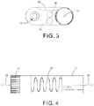
FIG. 2 is a top plan view of the first embodiment of the device suitable for use in practicing exemplary embodiments of this disclosure. -
FIG. 3 is an end view of the first embodiment of the device suitable for use in practicing exemplary embodiments of this disclosure. -
FIG. 4 is a side view of the first embodiment of the device suitable for use in practicing exemplary embodiments of this disclosure. -
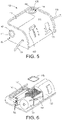
FIG. 5 is a perspective view of a second embodiment of a device suitable for use in practicing exemplary embodiments of this disclosure. -
FIG. 6 is a perspective view of the second embodiment of the device with the housing removed suitable for use in practicing exemplary embodiments of this disclosure. -
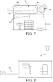
FIG. 7 is a top plan view of the second embodiment of the device suitable for use in practicing exemplary embodiments of this disclosure. -
FIG. 8 is a side view of the second embodiment of the device shown in use with a pair of scopes suitable for use in practicing exemplary embodiments of this disclosure. -
FIG. 9 is a top perspective view of a third embodiment of a device suitable for use in practicing exemplary embodiments of this disclosure. -
FIG. 10 is side perspective view of the third embodiment of the device suitable for use in practicing exemplary embodiments of this disclosure. -
FIG. 11 is perspective view of the third embodiment of the device in separated form suitable for use in practicing exemplary embodiments of this disclosure. -
FIG. 12 is a perspective view of the third embodiment of the device suitable for use in practicing exemplary embodiments of this disclosure. -
FIG. 13 is a logic flow diagram in accordance with a method and apparatus for performing exemplary embodiments of this disclosure. - At the outset, it should be clearly under stood that like reference numerals are intended to identify the same structural elements, portions or surfaces consistently throughout the several drawing figures, as such elements, portions or surfaces may be further described or explained by the entire written specification, of which this detailed description is an integral part. Unless otherwise indicated, the drawings are intended to be read (e.g., cross-hatching, arrangement of parts, proportion, debris, etc.) together with the specification, and are to be considered a portion of the entire written description of this invention. As used in the following description, the terms "horizontal.", "vertical", "left", "right", "up" and "down", as well as adjectival and adverbial derivatives thereof, (e.g., "horizontally", "rightwardly", "upwardly", etc.), simply refer to the orientation of the illustrated structure as the particular drawing figure faces the reader. Similarly, the terms "inwardly" and "outwardly" generally refer to the orientation of a surface relative to its axis of elongation, or of rotation, as appropriate.
- Embodiments of the present disclosure provide a device operable to interact with medical or surgical devices or tools (e.g., a scope for laparoscopic or endoscopic procedures, trocars, scalpels, and the like) such that the medical or surgical tools can be cleaned and/or defogged to aid in medical or surgical procedures. Embodiments of the present disclosure also provide a device operable to filter a flow of fluid from a patient's body (e.g., smoke or vapor from a patient's body cavity produced during surgery). Embodiments further provide a white balance for improved video/pictures from a scope during surgical or medical procedures. Embodiments of surgical or medical procedures include laparoscopy, endoscopy, arthroscopy, bronchoscopy, colonoscopy, cystoscopy, enteroscopy, hysteroscopy, laryngoscopy, mediastinoscopy, ureteroscopy, and other procedures involving a scope in a body cavity.
- Referring now to the drawings, and more particularly to
FIG. 1 thereof, embodiments of the present disclosure provide a fluid filtration, cleaning anddefogging device 10. In one embodiment, thedevice 10 includes ahousing 13. Thehousing 13 has afirst opening 16 for receiving a medical/surgical scope in a generally vertically oriented position and asecond opening 19 for receiving a scope in a generally horizontally oriented position. Anillumination element openings openings housing 13 to facilitate insertion of the surgical scopes and other medical devices in darker environments.Illumination devices device 10 is ready for use.Illumination devices device 10. In certain embodiments, theopenings frangible disc frangible discs seal openings housing 13 is closed and sealed to protect the internal components from exposure to outside elements. Amicrofiber wipe 22 may be mounted to the exterior of thehousing 13 such that a scope may be brought into contact with thewipe 22 to remove debris. This embodiment utilizes separate compartments to clean, warm and white balance a scope. - The first embodiment of the
device 10 also provides for fluid filtration. A conduit ortube 25 provides for an input passageway to a filter system disposed in thehousing 13. Theconduit 25 may be provided with a luer lock (not shown) that attaches to a conduit or trocar leading to a pressurized surgical site such as a laparascopy with a pneumoperitoneum. As shown inFIG. 4 , theconduit 25 leads to aliquid trap 29. Embodiments ofliquid trap 29 are operable to remove liquid such as condensed water vapor from a gas. Carbon or other odor removing media andparticulate filters 27 are disposed inside thehousing 13. Embodiments offilters 27 allow a flow of air or fluid throughconduit 25 while removing extraneous materials or debris from the air or fluid. Aflow selector 30 is disposed on the exterior of thehousing 13. A second conduit ortube 33 extending from the opposite end of thehousing 13 may be disposed in fluid communication with either a vacuum system or with atmosphere. The system may be manually or automatically switched between connection to a vacuum source or venting to atmosphere. Theflow selector 30 provides for adjustment of the flow through the filtration device without deflating the peritoneal cavity. - As shown in
FIGS. 2-3 , the first embodiment of the device may be provided with a power source such as one ormore batteries 35. As shown thebatteries 35 may be installed withinhousing 13 at a mid-portion of thedevice 10. Thebatteries 35 may be provided in a circuit for providing heat through electrical resistance in a printed circuit board (PCB). The circuit board may be designed to have multiple and separate heater sections built into the circuit. The circuit may be rigid or flexible. The device may be provided with an electronic control circuit to maintain PCB temperature of the heating circuit for warming the cleaning fluid. Also, the heating element can be a dedicated component separate from the circuit board. The heating element may be flexible or ridged to allow for a bundle of wire to be around the port to provide a heater. Heating can be provided to one or both ports oropenings - An alternate embodiment is shown in
FIG. 5 . Shown inFIG. 5 isdevice 100, which includes ahousing 103. Thehousing 103 has afirst opening 106 for receiving a scope in a generally vertically oriented position, and a second opening 109 for receiving a scope in a generally horizontally oriented position. A plurality ofillumination devices openings 106, 109 to facilitate insertion of the surgical scopes in darker environments. In certain embodiments, theopenings 106, 109 may be sealed by afrangible disc frangible discs housing 103 is closed and sealed to protect the internal components from exposure to outside elements. A microfiber wipe 112 may be mounted to the exterior of thehousing 103 such that a scope may be brought into contact with the wipe to remove debris and/or extraneous material. This embodiment utilizes separate compartments to clean, warm and white balance a scope. - The
device 100 also provides for fluid filtration. A conduit ortube 125 provides for an input passageway to a filter system disposed in thehousing 103. Theconduit 125 may be provided with a luer lock (not shown) that attaches to a conduit or trocar leading to a pressurized surgical site such as a laparascopy with a pneumoperitoneum. Theconduit 125 leads to aliquid trap 129 operable to remove liquid from a gas. Carbon or other odor removing media andparticulate filters 127 are disposed inside thehousing 103. Aflow selector 130 is disposed on the exterior of thehousing 103. Embodiments offlow selector 130 are operable to regulate and change upon user input a flow of gas or fluid throughconduit 25. A conduit ortube 133 extending from the opposite end of thehousing 103 may be disposed in fluid communication with either a vacuum system or with atmosphere. The system may be manually or automatically switched between connection to a vacuum source or venting to atmosphere. In the embodiment shown inFIG. 5 , thehousing 103 also includes awindow 138 for viewing levels of liquid trapped inliquid trap 129. - Turning to
FIG. 6 , with thehousing 103 removed for clarity, theflow selector 130 provides for adjustment of the flow through the filtration device without deflating the peritoneal cavity. The filter(s) 127 are disposed in alignment with the flow selector and may be positioned between theflow selector 130 and theliquid trap chamber 129. On the other side of the figure, acavity 145 may be formed to receive the scope vertically through thefirst opening 106. A cleaning material may be disposed at the bottom of the cavity. The cleaning material may comprise a sponge or other soft, porous material for receiving and holding a cleaning solution. Adjacent to thecavity 145, ahorizontal bed 148 provides for support of a horizontally disposed scope that is inserted through the second opening 109. - A power source such as one or
more batteries 155 may be mounted in a middle portion of the assembly. The power source may be used to provide power to a heater for the warming fluid for the scope. Thebatteries 155 may be provided in a circuit for providing heat through electrical resistance in a printedcircuit board 156. Thecircuit board 156 may be designed to have multiple and separate heater sections built into the circuit. Thecircuit board 156 may be rigid or flexible. The device may be provided with an electronic control circuit to maintain printed circuit board (PCB) 156 temperature of the heating circuit for warming the cleaning fluid maintained withincavity 145 and/orhorizontal bed 148. In another embodiment,device 100 can include a heating element (e.g., a resistance heating element) that is a dedicated component separate from the circuit board operable to provide heat to the cleaning fluid maintained within thecavity 145 and/orhorizontal bed 148. The heating element may be flexible or ridged to allow for a bundle of wire to be around the port to provide a heater. Heating can also be provided to one or both ports and may have independent temperatures. Embodiments ofcircuit board 156 and/or a heating element are operable to heat or warm the cleaning fluid maintained within thecavity 145 and/orhorizontal bed 148 such that there is not a substantial temperature change between the heated cleaning fluid and an interior of a body cavity. - Turning to
FIG. 7 , the horizontally disposed portion of the cleaning device may contain a sponge or pair of sponges or acleaning material 160 that is split to provide a channel for sliding the scope through the cleaning material. The twosponges 160 are configured to accept and towarm scopes 180, 185 (shown inFIG. 8 ) of all sizes. A V-shapedwhite reference material 165 may be disposed at the end of thecavity 148. The whitebalance reference material 165 is constructed of a non-porous material such as silicone. The whitebalance reference material 165 does not hold any liquid or cleaning solution and is arranged to provide a white balance for providing a reference color for optimizing the camera. The whitebalance reference material 165 is V-shaped so that scopes having different diameters may be inserted through the cleaningmaterial 160 and into contact with the whitebalance reference material 165. - Reference is now made to
FIG. 8 , which depicts a side view of thedevice 100 with afirst scope 180 being warmed via thefirst opening 106 and asecond scope 185 being cleaned and white balanced via the second opening 109. - Turning to
FIGS. 9-12 , illustrated is an alternative embodiment of the fluid filtration and cleaning anddefogging device 900. Thedevice 900 as shown inFIGS. 9-12 is similar to the device illustrated inFIG. 1 and may be equipped with any of the parts, features, designs, and/or functionality as described hereinabove with reference toFIGS. 1-8 . Shown inFIGS. 9-12 isdevice 900 having afirst opening 902 occluded by afrangible disc 904 operable to maintain a cleaning fluid.Device 900 also includes asecond opening 906 occluded by afrangible disc 908 operable to maintain a cleaning material, aconduit 910 having a filter and liquid trap. InFIG. 10 ,second opening 906 withfrangible disc 908 is shown located on a side face ofdevice 900.Conduit 910 operable to be removeably coupled to a surgical site to pass gas or fluid from within a body cavity throughconduit 910. It should be noted that in the embodiment illustrated inFIGS. 9-12 , the input and output ofconduit 910 is located adjacent to one another. The flow of gas or fluid throughconduit 910 can be operably regulated, changed or maintained byflow selector 912. Also shown is wipe 914 operable to remove extraneous material or debris from an opposing object, such as a medical or surgical tool. Embodiments ofdevice 900 also include a heating element operable to heat the cleaning fluid and cleaning materials withindevice 900. - This alternative embodiment, however further provides for a fluid filtration, cleaning, and defogging device having a modular design. In particular, as can be seen in
FIG. 11 , the device housing as discussed with reference toFIG. 1 may be divided into two detachable and self-contained housings that can be either joined together into a single unit or used separately as distinct devices, as desired by the user. Preferably, afirst housing portion 916 may be dedicated to providing a laparoscopic warming device, while asecond housing portion 918 may be dedicated to providing a peritoneal plume evaluator. WhileFIG. 11 illustrates afirst housing portion 916 attachable to asecond housing portion 918 by aclip 920, it is anticipated that any appropriate coupling mechanism (e.g., snap, clasp, lock, rib, etc.) may be used. It is further anticipated that power and/or electrical signals may be passed between a first housing portion and a second housing portion via thecoupling mechanism 920. - Reference is now made to
FIG. 13 , which depicts a simplified block diagram in accordance with an exemplary method of aiding medical procedures. The process begins atblock 1302 which states (a) providing a housing defining a first opening, a second opening, and an interior; (b) providing a first cleaning element maintained within the interior relative to the first opening, the first cleaning element comprising at least one cleaning agent operable to remove extraneous debris from an object; (c) providing a second cleaning element maintained with the interior relative to the second opening, the second cleaning element comprising at least one cleaning material and at least one white reference material, the at least one cleaning material operable to remove debris from an object; and (d) providing a conduit defining a passage from a first end of the housing to a second end of the housing, the conduit comprising at least one filter and at least one liquid trap, the conduit operable to allow a flow from the first end of the housing to the second end of the housing and to remove debris from the flow. Then block 1304 indicates wherein the housing further comprises a microfiber material fixedly attached to an outside surface of the housing. - Some of the non-limiting implementations detailed above are also summarized at
FIG. 13 followingblock 1304.Block 1306 relates to wherein the first opening is occluded by a first frangible disc operable to maintain the at least one cleaning agent within the first opening, and wherein the second opening is occluded by a second frangible disc.Block 1308 then states the conduit further comprising a flow selector operable to change a rate of flow of fluid through the conduit.Block 1310 goes on to state the first opening and the second opening each comprising at least one illumination device operable to at least partially indicate a location of the first opening and the second opening.Block 1312 then indicates the method further comprising providing a power source operably coupled to an electrical resistance element, the electrical resistance element operable to heat the interior. -
Block 1314 then relates wherein the electrical resistance element is a printed circuit board (PCB).Block 1316 states wherein the at least one cleaning agent is a porous material operable to receive and hold a cleaning solution. Finally,block 1318 indicates wherein the at least one cleaning material is a pair of sponges, and the at least one white reference material forms a V-shape operable to accept a scope. - The logic diagram on
FIG. 13 may be considered to illustrate the operation of a method, or a result of execution of computer program instructions stored in a computer-readable medium. The logic diagram ofFIG. 13 may also be considered a specific manner in which components of a device are configured to cause that device to operate, whether such device is a medical or surgical device or some other related device, or one or more components thereof. - Embodiments of the present invention may be provided with any of the aspects and features of the fluid filtration system as described in
U.S. Patent Application No. 14/884,544, filed on October 15, 2015 U.S. Patent Application No. 14/779, 986 filed May 6, 2015 - The invention has been described in detail with particular reference to a presently preferred embodiment, but it will be understood that variations and modifications can be effected within the spirit and scope of the invention. The presently disclosed embodiments are therefore considered in all respects to be illustrative and not restrictive. The scope of the invention is indicated by the appended claims, and all changes that come within the meaning and range of equivalents thereof are intended to be embraced therein.
Claims (12)
- An apparatus (10, 100, 900) for fluid filtration, cleaning, and defogging in medical procedures, the apparatus comprising:(a) a housing (13, 103) defining a first opening (16, 106, 902), a second opening (19, 109, 906), and an interior;(b) a first cleaning element maintained within the interior relative to the first opening (16, 106, 902), the first cleaning element comprising at least one cleaning agent operable to remove extraneous debris from an object;(c) a second cleaning element maintained with the interior relative to the second opening (19, 109, 906), the second cleaning element comprising at least one cleaning material (160) and at least one white reference material (165), the at least one cleaning material (160) operable to remove debris from an object; characterized by(d) a conduit (25, 125, 910) defining a passage from a first end of the housing (13, 103) to a second end of the housing (13, 103), the conduit (25, 125, 910) comprising at least one filter (27, 127) and at least one liquid trap (29, 129), the conduit (25, 125, 910) operable to allow a flow from the first end of the housing (13, 103) to the second end of the housing (13, 103) and to remove debris from the flow;wherein the conduit (25, 125, 910) further comprises a flow selector (30, 130, 912) operable to change a rate of flow of fluid through the conduit (25, 125, 910).
- The apparatus according to claim 1, wherein the housing (13, 103) further comprises a microfiber material (22, 112, 914) fixedly attached to an outside surface of the housing (13, 103).
- The apparatus according to claim 1, wherein the first opening (16, 106, 902) is occluded by a first frangible disc (20, 110, 904) operable to maintain the at least one cleaning agent within the first opening (16, 106, 902), and wherein the second opening (19, 109, 906) is occluded by a second frangible disc (21, 111, 908).
- The apparatus according to claim 1, the first opening (16, 106, 902) and the second opening (19, 109, 906) each comprising at least one illumination device (102, 104) operable to at least partially indicate a location of the first opening (16, 106, 902) and the second opening (19, 109, 906).
- The apparatus according to claim 1, the apparatus further comprising a power source (35, 155) operably coupled to an electrical resistance element (156), the electrical resistance element (156) operable to heat the interior, wherein preferably the electrical resistance element (156) is a printed circuit board (PCB).
- The apparatus according to claim 1, wherein the at least one cleaning agent is a porous material operable to receive and hold a cleaning solution, or wherein the at least one cleaning material (160) is a pair of sponges, and the at least one white reference material (165) forms a V-shape operable to accept a scope, or wherein the at least one liquid trap (29, 129), is operable to remove a liquid.
- A method of aiding medical procedures using the apparatus of any one of the claims 1 to 6, the method comprising:(a) providing a housing (13, 103) defining a first opening (16, 106, 902), a second opening (19, 109, 906), and an interior;(b) providing a first cleaning element maintained within the interior relative to the first opening (16, 106, 902), the first cleaning element comprising at least one cleaning agent operable to remove extraneous debris from an object;(c) providing a second cleaning element maintained with the interior relative to the second opening (19, 109, 906), the second cleaning element comprising at least one cleaning material (160) and at least one white reference material (165), the at least one cleaning material (160) operable to remove debris from an object; characterized by(d) providing a conduit (25, 125, 910) defining a passage from a first end of the housing (13, 103) to a second end of the housing (13, 103), the conduit (25, 125, 910) comprising at least one filter (27, 127) and at least one liquid trap (29, 129), the conduit (25, 125, 910) operable to allow a flow from the first end of the housing (13, 103) to the second end of the housing (13, 103) and to remove debris from the flow; wherein the conduit (25, 125, 910) further comprises a flow selector (30, 130, 912) operable to change a rate of flow of fluid through the conduit (25, 125, 910).
- The method according to claim 7, wherein the housing (13, 103) further comprises a microfiber material fixedly attached to an outside surface of the housing (13, 103).
- The method according to claim 7, wherein the first opening (16, 106, 902) is occluded by a first frangible disc (20, 110, 904) operable to maintain the at least one cleaning agent within the first opening (16, 106, 902), and wherein the second opening (19, 109, 906) is occluded by a second frangible disc (21, 111, 908).
- The method according to claim 7, the first opening (16, 106, 902) and the second opening (19, 109, 906) each comprising at least one illumination device (102, 104) operable to at least partially indicate a location of the first opening (16, 106, 902) and the second opening (19, 109, 906).
- The method according to claim 7, the method further comprising providing a power source (35, 155) operably coupled to an electrical resistance element, the electrical resistance element operable to heat the interior,
wherein preferably the electrical resistance element is a printed circuit board (PCB). - The method according to claim 7, wherein the at least one cleaning agent is a porous material operable to receive and hold a cleaning solution or wherein the at least one cleaning material (160) is a pair of sponges, and the at least one white reference material (165) forms a V-shape operable to accept a scope.
Applications Claiming Priority (3)
| Application Number | Priority Date | Filing Date | Title |
|---|---|---|---|
| US201562249613P | 2015-11-02 | 2015-11-02 | |
| US201662287817P | 2016-01-27 | 2016-01-27 | |
| PCT/US2016/060140 WO2017079318A1 (en) | 2015-11-02 | 2016-11-02 | Fluid filtration, cleaning, and defogging device |
Publications (3)
| Publication Number | Publication Date |
|---|---|
| EP3352642A1 EP3352642A1 (en) | 2018-08-01 |
| EP3352642A4 EP3352642A4 (en) | 2019-10-30 |
| EP3352642B1 true EP3352642B1 (en) | 2022-07-27 |
Family
ID=58638107
Family Applications (1)
| Application Number | Title | Priority Date | Filing Date |
|---|---|---|---|
| EP16862890.7A Active EP3352642B1 (en) | 2015-11-02 | 2016-11-02 | Fluid filtration, cleaning, and defogging device |
Country Status (6)
| Country | Link |
|---|---|
| US (3) | US10426327B2 (en) |
| EP (1) | EP3352642B1 (en) |
| AU (1) | AU2016349880B2 (en) |
| CA (1) | CA3003450C (en) |
| ES (1) | ES2928074T3 (en) |
| WO (1) | WO2017079318A1 (en) |
Families Citing this family (3)
| Publication number | Priority date | Publication date | Assignee | Title |
|---|---|---|---|---|
| USD868997S1 (en) | 2017-09-15 | 2019-12-03 | Adventist Health System/Sunbelt, Inc. | Scope warmer apparatus |
| US20190159665A1 (en) * | 2017-11-28 | 2019-05-30 | Covidien Lp | Devices for cleaning medical videoscopes |
| CN113510109B (en) * | 2021-04-23 | 2022-10-14 | 安徽捷泰智能科技有限公司 | Channel surface repairing device for color sorter |
Family Cites Families (11)
| Publication number | Priority date | Publication date | Assignee | Title |
|---|---|---|---|---|
| US5274874A (en) * | 1992-03-13 | 1994-01-04 | Merocel Corporation | Endoscope cleaning and defogging apparatus |
| US5880779A (en) * | 1997-06-09 | 1999-03-09 | Rhynes; Vincent | Sterile disposable white balance box |
| AU2001238377A1 (en) * | 2000-02-18 | 2001-08-27 | University Of Massachussets | Devices and methods for warming and cleaning lenses of optical surgical instruments |
| US9060676B2 (en) | 2004-04-05 | 2015-06-23 | Fisher & Paykel Healthcare Limited | Scope warming device with whitening element |
| US8152717B2 (en) * | 2006-01-30 | 2012-04-10 | Ricardo Alexander Gomez | Device for white balancing and appying an anti-fog agent to medical videoscopes prior to medical procedures |
| JP2010253156A (en) * | 2009-04-28 | 2010-11-11 | Fujifilm Corp | Endoscope system, endoscope, and endoscope driving method |
| US9415160B2 (en) | 2012-05-21 | 2016-08-16 | Buffalo Filter Llc | Fluid filtration device and system |
| US8608816B2 (en) * | 2012-01-10 | 2013-12-17 | Buffalo Filter Llc | Fluid filtration device and system |
| US9867914B2 (en) * | 2012-01-10 | 2018-01-16 | Buffalo Filter Llc | Fluid filtration device and system |
| AU2015256076B2 (en) * | 2014-05-06 | 2019-05-16 | Buffalo Filter Llc | Laparoscope and endoscope cleaning and defogging device |
| CN107106000A (en) * | 2015-01-15 | 2017-08-29 | 柯惠Lp公司 | Devices for containing surgical tools before and during medical procedures |
-
2016
- 2016-11-02 CA CA3003450A patent/CA3003450C/en active Active
- 2016-11-02 AU AU2016349880A patent/AU2016349880B2/en active Active
- 2016-11-02 EP EP16862890.7A patent/EP3352642B1/en active Active
- 2016-11-02 US US15/341,757 patent/US10426327B2/en active Active
- 2016-11-02 ES ES16862890T patent/ES2928074T3/en active Active
- 2016-11-02 WO PCT/US2016/060140 patent/WO2017079318A1/en not_active Ceased
-
2019
- 2019-08-20 US US16/545,385 patent/US11026568B2/en active Active
-
2021
- 2021-05-10 US US17/316,133 patent/US11627872B2/en active Active
Also Published As
| Publication number | Publication date |
|---|---|
| US11026568B2 (en) | 2021-06-08 |
| AU2016349880B2 (en) | 2020-04-02 |
| CA3003450C (en) | 2020-06-16 |
| EP3352642A4 (en) | 2019-10-30 |
| US20210259534A1 (en) | 2021-08-26 |
| AU2016349880A1 (en) | 2018-05-17 |
| US11627872B2 (en) | 2023-04-18 |
| US20170120308A1 (en) | 2017-05-04 |
| US20190374097A1 (en) | 2019-12-12 |
| ES2928074T3 (en) | 2022-11-15 |
| US10426327B2 (en) | 2019-10-01 |
| EP3352642A1 (en) | 2018-08-01 |
| CA3003450A1 (en) | 2017-05-11 |
| WO2017079318A1 (en) | 2017-05-11 |
Similar Documents
| Publication | Publication Date | Title |
|---|---|---|
| US11627872B2 (en) | Fluid filtration, cleaning, and defogging device | |
| US9775502B2 (en) | Laparascope and endoscope cleaning and defogging device | |
| US9968242B2 (en) | Suction control unit for an endoscope having two working channels | |
| US9078562B2 (en) | Systems and methods for optimizing and maintaining visualization of a surgical field during the use of surgical scopes | |
| JP6381616B2 (en) | Flexible electronic circuit board for multi-camera endoscope | |
| US9050036B2 (en) | Device for maintaining visualization with surgical scopes | |
| EP3062835B1 (en) | Fluid filtration device and system | |
| EP2279704B1 (en) | Single port device having integral filter/vent | |
| US20160114281A1 (en) | Fluid Filtration Device and System | |
| US20100168520A1 (en) | View optimizer and stabilizer for use with surgical scopes | |
| US20120022331A1 (en) | Systems and Methods for Optimizing and Maintaining Visualization of a Surgical Field During the Use of Surgical Scopes | |
| EP3362124B1 (en) | Fluid filtration device and system |
Legal Events
| Date | Code | Title | Description |
|---|---|---|---|
| STAA | Information on the status of an ep patent application or granted ep patent |
Free format text: STATUS: THE INTERNATIONAL PUBLICATION HAS BEEN MADE |
|
| PUAI | Public reference made under article 153(3) epc to a published international application that has entered the european phase |
Free format text: ORIGINAL CODE: 0009012 |
|
| STAA | Information on the status of an ep patent application or granted ep patent |
Free format text: STATUS: REQUEST FOR EXAMINATION WAS MADE |
|
| 17P | Request for examination filed |
Effective date: 20180425 |
|
| AK | Designated contracting states |
Kind code of ref document: A1 Designated state(s): AL AT BE BG CH CY CZ DE DK EE ES FI FR GB GR HR HU IE IS IT LI LT LU LV MC MK MT NL NO PL PT RO RS SE SI SK SM TR |
|
| AX | Request for extension of the european patent |
Extension state: BA ME |
|
| DAV | Request for validation of the european patent (deleted) | ||
| DAX | Request for extension of the european patent (deleted) | ||
| A4 | Supplementary search report drawn up and despatched |
Effective date: 20191002 |
|
| RIC1 | Information provided on ipc code assigned before grant |
Ipc: A61B 1/12 20060101AFI20190926BHEP |
|
| STAA | Information on the status of an ep patent application or granted ep patent |
Free format text: STATUS: EXAMINATION IS IN PROGRESS |
|
| 17Q | First examination report despatched |
Effective date: 20210812 |
|
| GRAP | Despatch of communication of intention to grant a patent |
Free format text: ORIGINAL CODE: EPIDOSNIGR1 |
|
| STAA | Information on the status of an ep patent application or granted ep patent |
Free format text: STATUS: GRANT OF PATENT IS INTENDED |
|
| INTG | Intention to grant announced |
Effective date: 20220223 |
|
| GRAS | Grant fee paid |
Free format text: ORIGINAL CODE: EPIDOSNIGR3 |
|
| GRAA | (expected) grant |
Free format text: ORIGINAL CODE: 0009210 |
|
| STAA | Information on the status of an ep patent application or granted ep patent |
Free format text: STATUS: THE PATENT HAS BEEN GRANTED |
|
| AK | Designated contracting states |
Kind code of ref document: B1 Designated state(s): AL AT BE BG CH CY CZ DE DK EE ES FI FR GB GR HR HU IE IS IT LI LT LU LV MC MK MT NL NO PL PT RO RS SE SI SK SM TR |
|
| REG | Reference to a national code |
Ref country code: CH Ref legal event code: EP |
|
| REG | Reference to a national code |
Ref country code: DE Ref legal event code: R096 Ref document number: 602016073853 Country of ref document: DE |
|
| REG | Reference to a national code |
Ref country code: AT Ref legal event code: REF Ref document number: 1506509 Country of ref document: AT Kind code of ref document: T Effective date: 20220815 |
|
| REG | Reference to a national code |
Ref country code: IE Ref legal event code: FG4D |
|
| REG | Reference to a national code |
Ref country code: LT Ref legal event code: MG9D |
|
| REG | Reference to a national code |
Ref country code: ES Ref legal event code: FG2A Ref document number: 2928074 Country of ref document: ES Kind code of ref document: T3 Effective date: 20221115 |
|
| REG | Reference to a national code |
Ref country code: NL Ref legal event code: MP Effective date: 20220727 |
|
| PG25 | Lapsed in a contracting state [announced via postgrant information from national office to epo] |
Ref country code: SE Free format text: LAPSE BECAUSE OF FAILURE TO SUBMIT A TRANSLATION OF THE DESCRIPTION OR TO PAY THE FEE WITHIN THE PRESCRIBED TIME-LIMIT Effective date: 20220727 Ref country code: RS Free format text: LAPSE BECAUSE OF FAILURE TO SUBMIT A TRANSLATION OF THE DESCRIPTION OR TO PAY THE FEE WITHIN THE PRESCRIBED TIME-LIMIT Effective date: 20220727 Ref country code: PT Free format text: LAPSE BECAUSE OF FAILURE TO SUBMIT A TRANSLATION OF THE DESCRIPTION OR TO PAY THE FEE WITHIN THE PRESCRIBED TIME-LIMIT Effective date: 20221128 Ref country code: NO Free format text: LAPSE BECAUSE OF FAILURE TO SUBMIT A TRANSLATION OF THE DESCRIPTION OR TO PAY THE FEE WITHIN THE PRESCRIBED TIME-LIMIT Effective date: 20221027 Ref country code: NL Free format text: LAPSE BECAUSE OF FAILURE TO SUBMIT A TRANSLATION OF THE DESCRIPTION OR TO PAY THE FEE WITHIN THE PRESCRIBED TIME-LIMIT Effective date: 20220727 Ref country code: LV Free format text: LAPSE BECAUSE OF FAILURE TO SUBMIT A TRANSLATION OF THE DESCRIPTION OR TO PAY THE FEE WITHIN THE PRESCRIBED TIME-LIMIT Effective date: 20220727 Ref country code: LT Free format text: LAPSE BECAUSE OF FAILURE TO SUBMIT A TRANSLATION OF THE DESCRIPTION OR TO PAY THE FEE WITHIN THE PRESCRIBED TIME-LIMIT Effective date: 20220727 Ref country code: FI Free format text: LAPSE BECAUSE OF FAILURE TO SUBMIT A TRANSLATION OF THE DESCRIPTION OR TO PAY THE FEE WITHIN THE PRESCRIBED TIME-LIMIT Effective date: 20220727 |
|
| REG | Reference to a national code |
Ref country code: AT Ref legal event code: MK05 Ref document number: 1506509 Country of ref document: AT Kind code of ref document: T Effective date: 20220727 |
|
| PG25 | Lapsed in a contracting state [announced via postgrant information from national office to epo] |
Ref country code: PL Free format text: LAPSE BECAUSE OF FAILURE TO SUBMIT A TRANSLATION OF THE DESCRIPTION OR TO PAY THE FEE WITHIN THE PRESCRIBED TIME-LIMIT Effective date: 20220727 Ref country code: IS Free format text: LAPSE BECAUSE OF FAILURE TO SUBMIT A TRANSLATION OF THE DESCRIPTION OR TO PAY THE FEE WITHIN THE PRESCRIBED TIME-LIMIT Effective date: 20221127 Ref country code: HR Free format text: LAPSE BECAUSE OF FAILURE TO SUBMIT A TRANSLATION OF THE DESCRIPTION OR TO PAY THE FEE WITHIN THE PRESCRIBED TIME-LIMIT Effective date: 20220727 Ref country code: GR Free format text: LAPSE BECAUSE OF FAILURE TO SUBMIT A TRANSLATION OF THE DESCRIPTION OR TO PAY THE FEE WITHIN THE PRESCRIBED TIME-LIMIT Effective date: 20221028 |
|
| PG25 | Lapsed in a contracting state [announced via postgrant information from national office to epo] |
Ref country code: SM Free format text: LAPSE BECAUSE OF FAILURE TO SUBMIT A TRANSLATION OF THE DESCRIPTION OR TO PAY THE FEE WITHIN THE PRESCRIBED TIME-LIMIT Effective date: 20220727 Ref country code: RO Free format text: LAPSE BECAUSE OF FAILURE TO SUBMIT A TRANSLATION OF THE DESCRIPTION OR TO PAY THE FEE WITHIN THE PRESCRIBED TIME-LIMIT Effective date: 20220727 Ref country code: DK Free format text: LAPSE BECAUSE OF FAILURE TO SUBMIT A TRANSLATION OF THE DESCRIPTION OR TO PAY THE FEE WITHIN THE PRESCRIBED TIME-LIMIT Effective date: 20220727 Ref country code: CZ Free format text: LAPSE BECAUSE OF FAILURE TO SUBMIT A TRANSLATION OF THE DESCRIPTION OR TO PAY THE FEE WITHIN THE PRESCRIBED TIME-LIMIT Effective date: 20220727 Ref country code: AT Free format text: LAPSE BECAUSE OF FAILURE TO SUBMIT A TRANSLATION OF THE DESCRIPTION OR TO PAY THE FEE WITHIN THE PRESCRIBED TIME-LIMIT Effective date: 20220727 |
|
| REG | Reference to a national code |
Ref country code: DE Ref legal event code: R097 Ref document number: 602016073853 Country of ref document: DE |
|
| PG25 | Lapsed in a contracting state [announced via postgrant information from national office to epo] |
Ref country code: SK Free format text: LAPSE BECAUSE OF FAILURE TO SUBMIT A TRANSLATION OF THE DESCRIPTION OR TO PAY THE FEE WITHIN THE PRESCRIBED TIME-LIMIT Effective date: 20220727 Ref country code: EE Free format text: LAPSE BECAUSE OF FAILURE TO SUBMIT A TRANSLATION OF THE DESCRIPTION OR TO PAY THE FEE WITHIN THE PRESCRIBED TIME-LIMIT Effective date: 20220727 |
|
| PLBE | No opposition filed within time limit |
Free format text: ORIGINAL CODE: 0009261 |
|
| STAA | Information on the status of an ep patent application or granted ep patent |
Free format text: STATUS: NO OPPOSITION FILED WITHIN TIME LIMIT |
|
| PG25 | Lapsed in a contracting state [announced via postgrant information from national office to epo] |
Ref country code: MC Free format text: LAPSE BECAUSE OF FAILURE TO SUBMIT A TRANSLATION OF THE DESCRIPTION OR TO PAY THE FEE WITHIN THE PRESCRIBED TIME-LIMIT Effective date: 20220727 Ref country code: AL Free format text: LAPSE BECAUSE OF FAILURE TO SUBMIT A TRANSLATION OF THE DESCRIPTION OR TO PAY THE FEE WITHIN THE PRESCRIBED TIME-LIMIT Effective date: 20220727 |
|
| REG | Reference to a national code |
Ref country code: CH Ref legal event code: PL |
|
| 26N | No opposition filed |
Effective date: 20230502 |
|
| P01 | Opt-out of the competence of the unified patent court (upc) registered |
Effective date: 20230529 |
|
| REG | Reference to a national code |
Ref country code: BE Ref legal event code: MM Effective date: 20221130 |
|
| PG25 | Lapsed in a contracting state [announced via postgrant information from national office to epo] |
Ref country code: LI Free format text: LAPSE BECAUSE OF NON-PAYMENT OF DUE FEES Effective date: 20221130 Ref country code: CH Free format text: LAPSE BECAUSE OF NON-PAYMENT OF DUE FEES Effective date: 20221130 |
|
| PG25 | Lapsed in a contracting state [announced via postgrant information from national office to epo] |
Ref country code: SI Free format text: LAPSE BECAUSE OF FAILURE TO SUBMIT A TRANSLATION OF THE DESCRIPTION OR TO PAY THE FEE WITHIN THE PRESCRIBED TIME-LIMIT Effective date: 20220727 Ref country code: LU Free format text: LAPSE BECAUSE OF NON-PAYMENT OF DUE FEES Effective date: 20221102 |
|
| PG25 | Lapsed in a contracting state [announced via postgrant information from national office to epo] |
Ref country code: IE Free format text: LAPSE BECAUSE OF NON-PAYMENT OF DUE FEES Effective date: 20221102 |
|
| PG25 | Lapsed in a contracting state [announced via postgrant information from national office to epo] |
Ref country code: BE Free format text: LAPSE BECAUSE OF NON-PAYMENT OF DUE FEES Effective date: 20221130 |
|
| PG25 | Lapsed in a contracting state [announced via postgrant information from national office to epo] |
Ref country code: HU Free format text: LAPSE BECAUSE OF FAILURE TO SUBMIT A TRANSLATION OF THE DESCRIPTION OR TO PAY THE FEE WITHIN THE PRESCRIBED TIME-LIMIT; INVALID AB INITIO Effective date: 20161102 |
|
| PG25 | Lapsed in a contracting state [announced via postgrant information from national office to epo] |
Ref country code: CY Free format text: LAPSE BECAUSE OF FAILURE TO SUBMIT A TRANSLATION OF THE DESCRIPTION OR TO PAY THE FEE WITHIN THE PRESCRIBED TIME-LIMIT Effective date: 20220727 |
|
| PG25 | Lapsed in a contracting state [announced via postgrant information from national office to epo] |
Ref country code: MK Free format text: LAPSE BECAUSE OF FAILURE TO SUBMIT A TRANSLATION OF THE DESCRIPTION OR TO PAY THE FEE WITHIN THE PRESCRIBED TIME-LIMIT Effective date: 20220727 |
|
| PG25 | Lapsed in a contracting state [announced via postgrant information from national office to epo] |
Ref country code: TR Free format text: LAPSE BECAUSE OF FAILURE TO SUBMIT A TRANSLATION OF THE DESCRIPTION OR TO PAY THE FEE WITHIN THE PRESCRIBED TIME-LIMIT Effective date: 20220727 |
|
| PG25 | Lapsed in a contracting state [announced via postgrant information from national office to epo] |
Ref country code: BG Free format text: LAPSE BECAUSE OF FAILURE TO SUBMIT A TRANSLATION OF THE DESCRIPTION OR TO PAY THE FEE WITHIN THE PRESCRIBED TIME-LIMIT Effective date: 20220727 |
|
| PG25 | Lapsed in a contracting state [announced via postgrant information from national office to epo] |
Ref country code: MT Free format text: LAPSE BECAUSE OF FAILURE TO SUBMIT A TRANSLATION OF THE DESCRIPTION OR TO PAY THE FEE WITHIN THE PRESCRIBED TIME-LIMIT Effective date: 20220727 |
|
| PGFP | Annual fee paid to national office [announced via postgrant information from national office to epo] |
Ref country code: DE Payment date: 20251028 Year of fee payment: 10 |
|
| PGFP | Annual fee paid to national office [announced via postgrant information from national office to epo] |
Ref country code: GB Payment date: 20251023 Year of fee payment: 10 |
|
| PGFP | Annual fee paid to national office [announced via postgrant information from national office to epo] |
Ref country code: IT Payment date: 20251030 Year of fee payment: 10 |
|
| PGFP | Annual fee paid to national office [announced via postgrant information from national office to epo] |
Ref country code: FR Payment date: 20251110 Year of fee payment: 10 |
|
| PGFP | Annual fee paid to national office [announced via postgrant information from national office to epo] |
Ref country code: ES Payment date: 20251212 Year of fee payment: 10 |