EP3352639B1 - Dish washing machine - Google Patents
Dish washing machine Download PDFInfo
- Publication number
- EP3352639B1 EP3352639B1 EP16864599.2A EP16864599A EP3352639B1 EP 3352639 B1 EP3352639 B1 EP 3352639B1 EP 16864599 A EP16864599 A EP 16864599A EP 3352639 B1 EP3352639 B1 EP 3352639B1
- Authority
- EP
- European Patent Office
- Prior art keywords
- guide rail
- washing machine
- door
- dish washing
- lifting device
- Prior art date
- Legal status (The legal status is an assumption and is not a legal conclusion. Google has not performed a legal analysis and makes no representation as to the accuracy of the status listed.)
- Active
Links
Images







Classifications
-
- A—HUMAN NECESSITIES
- A47—FURNITURE; DOMESTIC ARTICLES OR APPLIANCES; COFFEE MILLS; SPICE MILLS; SUCTION CLEANERS IN GENERAL
- A47L—DOMESTIC WASHING OR CLEANING; SUCTION CLEANERS IN GENERAL
- A47L15/00—Washing or rinsing machines for crockery or tableware
- A47L15/42—Details
- A47L15/50—Racks ; Baskets
- A47L15/506—Arrangements for lifting racks for loading or unloading purposes
-
- A—HUMAN NECESSITIES
- A47—FURNITURE; DOMESTIC ARTICLES OR APPLIANCES; COFFEE MILLS; SPICE MILLS; SUCTION CLEANERS IN GENERAL
- A47L—DOMESTIC WASHING OR CLEANING; SUCTION CLEANERS IN GENERAL
- A47L15/00—Washing or rinsing machines for crockery or tableware
- A47L15/14—Washing or rinsing machines for crockery or tableware with stationary crockery baskets and spraying devices within the cleaning chamber
- A47L15/16—Washing or rinsing machines for crockery or tableware with stationary crockery baskets and spraying devices within the cleaning chamber with rigidly-mounted spraying devices
-
- A—HUMAN NECESSITIES
- A47—FURNITURE; DOMESTIC ARTICLES OR APPLIANCES; COFFEE MILLS; SPICE MILLS; SUCTION CLEANERS IN GENERAL
- A47L—DOMESTIC WASHING OR CLEANING; SUCTION CLEANERS IN GENERAL
- A47L15/00—Washing or rinsing machines for crockery or tableware
- A47L15/14—Washing or rinsing machines for crockery or tableware with stationary crockery baskets and spraying devices within the cleaning chamber
- A47L15/18—Washing or rinsing machines for crockery or tableware with stationary crockery baskets and spraying devices within the cleaning chamber with movably-mounted spraying devices
- A47L15/22—Rotary spraying devices
-
- A—HUMAN NECESSITIES
- A47—FURNITURE; DOMESTIC ARTICLES OR APPLIANCES; COFFEE MILLS; SPICE MILLS; SUCTION CLEANERS IN GENERAL
- A47L—DOMESTIC WASHING OR CLEANING; SUCTION CLEANERS IN GENERAL
- A47L15/00—Washing or rinsing machines for crockery or tableware
- A47L15/42—Details
- A47L15/4214—Water supply, recirculation or discharge arrangements; Devices therefor
- A47L15/4219—Water recirculation
- A47L15/4221—Arrangements for redirection of washing water, e.g. water diverters to selectively supply the spray arms
-
- A—HUMAN NECESSITIES
- A47—FURNITURE; DOMESTIC ARTICLES OR APPLIANCES; COFFEE MILLS; SPICE MILLS; SUCTION CLEANERS IN GENERAL
- A47L—DOMESTIC WASHING OR CLEANING; SUCTION CLEANERS IN GENERAL
- A47L15/00—Washing or rinsing machines for crockery or tableware
- A47L15/42—Details
- A47L15/4214—Water supply, recirculation or discharge arrangements; Devices therefor
- A47L15/4225—Arrangements or adaption of recirculation or discharge pumps
-
- A—HUMAN NECESSITIES
- A47—FURNITURE; DOMESTIC ARTICLES OR APPLIANCES; COFFEE MILLS; SPICE MILLS; SUCTION CLEANERS IN GENERAL
- A47L—DOMESTIC WASHING OR CLEANING; SUCTION CLEANERS IN GENERAL
- A47L15/00—Washing or rinsing machines for crockery or tableware
- A47L15/42—Details
- A47L15/4251—Details of the casing
- A47L15/4257—Details of the loading door
-
- A—HUMAN NECESSITIES
- A47—FURNITURE; DOMESTIC ARTICLES OR APPLIANCES; COFFEE MILLS; SPICE MILLS; SUCTION CLEANERS IN GENERAL
- A47L—DOMESTIC WASHING OR CLEANING; SUCTION CLEANERS IN GENERAL
- A47L15/00—Washing or rinsing machines for crockery or tableware
- A47L15/42—Details
- A47L15/4285—Water-heater arrangements
-
- A—HUMAN NECESSITIES
- A47—FURNITURE; DOMESTIC ARTICLES OR APPLIANCES; COFFEE MILLS; SPICE MILLS; SUCTION CLEANERS IN GENERAL
- A47L—DOMESTIC WASHING OR CLEANING; SUCTION CLEANERS IN GENERAL
- A47L15/00—Washing or rinsing machines for crockery or tableware
- A47L15/42—Details
- A47L15/50—Racks ; Baskets
- A47L15/507—Arrangements for extracting racks, e.g. roller supports
-
- A—HUMAN NECESSITIES
- A47—FURNITURE; DOMESTIC ARTICLES OR APPLIANCES; COFFEE MILLS; SPICE MILLS; SUCTION CLEANERS IN GENERAL
- A47B—TABLES; DESKS; OFFICE FURNITURE; CABINETS; DRAWERS; GENERAL DETAILS OF FURNITURE
- A47B88/00—Drawers for tables, cabinets or like furniture; Guides for drawers
- A47B88/90—Constructional details of drawers
- A47B2088/901—Drawers having a lifting mechanism
-
- A—HUMAN NECESSITIES
- A47—FURNITURE; DOMESTIC ARTICLES OR APPLIANCES; COFFEE MILLS; SPICE MILLS; SUCTION CLEANERS IN GENERAL
- A47B—TABLES; DESKS; OFFICE FURNITURE; CABINETS; DRAWERS; GENERAL DETAILS OF FURNITURE
- A47B46/00—Cabinets, racks or shelf units, having one or more surfaces adapted to be brought into position for use by extending or pivoting
- A47B46/005—Cabinets, racks or shelf units, having one or more surfaces adapted to be brought into position for use by extending or pivoting by displacement in a vertical plane; by rotating about a horizontal axis
Definitions
- Embodiments of the disclosure relate to a dish washing machine, and more particularly, to a dish washing machine which removes inconvenience of using a lower basket.
- a dish washing machine is an apparatus which jets washing water at a high pressure to dishes to wash, and generally a preliminary washing operation, a main washing operation, a rinsing operation, and a drying operation are performed.
- a preliminary washing operation garbage on dishes is removed by jetting washing water without a detergent.
- a detergent is added by a detergent supply device simultaneously with jetting washing water for washing dishes.
- baskets for loading dishes to be washed are installed at the top and bottom in a dish washing machine, and an upper basket and a lower basket may be independently inserted into or drawn out from the dish washing machine.
- the lower basket of the dish washing machine is large and heavy and used for washing a large amount of dishes.
- KR 10-0220731 B1 discloses a dishwasher having a door to be opened and closed in a hinged manner, an upper basket, and a lower basket, wherein basket transfer means are arranged at an inner surface of the door which allow a vertical transfer of the lower basket.
- US 2008/0018215 A1 discloses A refrigerator including a cabinet within which is arranged an upper fresh food compartment and a lower freezer compartment, wherein a freezer basket is slidingly supported in the freezer compartment, preferably for concurrent movement with a freezer door and wherein the freezer basket is coupled to a lifting mechanism that selectively shifts the freezer basket from a first or lowered position to a second or raised position in order to facilitate removal of items from the freezer basket.
- US 2008/0129168 A1 discloses a rack support system for a lower rack in a dishwasher including a frame configured to support the lower rack, and a linkage system coupling the frame to a side wall of the tub such that the lower rack is movable between a retracted position within the wash chamber and an extended position wherein the lower rack extends from the wash chamber, wherein the lower rack is movable within a range between a lowered position and an elevated position with the lower rack extended from the wash chamber.
- US 5,115,822 A discloses a dishwasher lower basket assembly including a dish holding basket and a lift mechanism for elevating the basket above the dishwasher door to a position adjacent the upper dish holding basket of the dishwasher.
- a dish washing machine including a lifting device for moving a lower basket up and down to remove inconvenience of using the lower basket of the dish washing machine.
- a dish washing machine may include a washing tub with an open front, a basket configured to be inserted into or drawn out from the washing tub through the open front of the washing tub, a door configured to open or close the open front of the washing tub, at least one guide rail configured to mount the basket on the door when the basket is drawn out from the washing tub while the door is open, and a lifting device configured to raise and lower the at least one guide rail between a raised position and a lowered position respectively, wherein the lifting device includes at least one link member pivotably provided at the door, wherein the at least one link member includes a pair of link members arranged to at least partially overlap each other when the at least one guide rail is in the lowered Position, wherein the lifting device further includes a link connecting member connecting the pair of link members which is accommodated in an inner space provided between the pair of link members arranged to overlap each her, wherein the link connecting member is surrounded by the pair of link members.
- the lifting device may be enclosed inside the door when the guide rail is in the lowered position and may be exposed outside the door when the guide rail is in the raised position.
- the lifting device may include at least one elastic member configured to provide an elastic restoring force in a direction in which the guide rail moves upward.
- the lifting device may further include the pair of link members arranged parallel to each other to support the guide rail, and the at least one elastic member may be disposed between the pair of link members.
- the door may further include at least one slowing device configured to reduce at least one of a speed at which the at least one guide rail is raised and a speed at which the at least one guide rail is lowered.
- the slowing device may include an operating body configured to reciprocate and to apply a force to the lifting device and a damping spring may provide an elastic restoring force to the operating body.
- the at least one link member may include a rotation stopper configured to limit a rotation angle of the at least one link member.
- the basket may include a plurality of rollers at a bottom thereof, and the at least one guide rail may include a rail groove on which the plurality of rollers are mounted.
- the at least one guide rail may further include a roller stopper configured to limit a movement of the plurality of rollers.
- the at least one guide rail may include a pair of guide rails arranged paralled to one another.
- the dish washing machine may further include a cover member configured to cover the lifting device when the at least one guide rail is in the lowered position.
- the cover member may include a sealing portion configured to prevent washing water from permeating the lifting device when the cover member covers the lifting device.
- a dish washing machine may include a washing tub having an open portion, a basket and a door configured to open or close the open portion of the washing tub, the door may include a front surface that faces away from the open the open portion of the washing tub when the door is closed, and a rear surface that faces away from the open portion of the washing tub when the door is closed, wherein a distance between at least a portion of the rear surface of the door and the front surface of the door is changeable so as to raise or lower the basket when the basket is drawn out from the washing tub.
- the door may include at least one guide rail disposed on the rear surface of the door and configured to guide the basket when the basket is drawn out from the washing tub and a lifting device configured to raise and lower the at least one guide rail.
- the lifting device may be accommodated between the front surface and the rear surface of the door when the at least one guide rail is in a lowered position.
- the door may further include a cover member configured to cover the lifting device when the at least one guide rail is in the lowered position.
- the lifting device may further include a damper disposed below the at least one guide rail and configured to provide a damping force in a direction for reducing a movement speed of the at least one guide rail.
- a dish washing machine in accordance with one or more embodiments of the disclosure may increase convenience for a user when loading dishes in or unloading dishes from a lower basket.
- a dish washing machine in accordance with one or more embodiments of the disclosure may reduce a space occupied by a lifting device, thus not reducing washing space. Also, a dish washing machine in accordance with one or more embodiments of the disclosure may reduce a garbage blocking phenomenon which occurs during washing or draining.
- a dish washing machine in accordance with one or more embodiments of the disclosure may include a lifting device for moving a lower basket up and down using a small force.
- FIG. 1 is a cross-sectional view of a dish washing machine in accordance with an embodiment of the disclosure.
- a dish washing machine 1 may include a body 10 which forms an exterior, a washing tub 12 provided in the body 10, baskets 14a and 14b provided in the washing tub 12 to store dishes, a sump 20 which collects and stores washing water, and jet units 41, 42, and 43 which jet washing water.
- the washing tub 12 is formed in an approximate box shape and has an open front for putting in or taking out dishes.
- the open front of the washing tub 12 may be opened and closed by a door 11.
- the doors 11 may be pivotably coupled with the body 10.
- the baskets 14a and 14b may include an upper basket 14a and a lower basket 14b.
- the upper basket 14a may be supported by an upper rail 13a
- the lower basket 14b may be supported by a lower rail 13b.
- the upper basket 14a and the lower basket 14b may be configured to be slidable forward and backward in the washing tub 12 due to the upper rail 13a and the lower rail 13b.
- Water stored in the sump 20 may include a washing pump 21 which pumps the stored water to the jet units 41, 42, and 43. Washing water pumped by the washing pump 21 may be supplied to a first jet unit 41 and a second jet unit 42 through a first supply pipe 31 and to a third jet unit 43 through a second supply pipe 32.
- a heater 16 for heating washing water and a drain pump 22 for draining washing water may be provided at a bottom of the washing tub 12.
- the first jet unit 41 may be provided above the upper basket 14a
- the second jet unit 42 may be provided between the upper basket 14a and the lower basket 14b
- the third jet unit 43 may be provided below the lower basket 14b.
- first jet unit 41 may be configured to rotate about a rotating shaft 41a
- second jet unit 42 may be configured to rotate about a rotating shaft 42a.
- the first jet unit 41 may jet washing water toward dishes stored in the upper basket 14a
- the second jet unit 42 may jet washing water toward dishes stored in the lower basket 14b.
- the third jet unit 43 may be provided at one side of the washing tub 12, unlike the first jet unit 41 and the second jet unit 42.
- the third jet unit 43 may jet washing water in an approximate horizontal direction. Accordingly, the washing water jetted by the third jet unit 43 may be not directly jetted toward the dishes.
- the third jet unit 43 may include a nozzle 44 which jets washing water.
- the nozzles 44 may be arranged in a row, at a certain regular spacing approximately from one side of the washing tub 12 to the opposite side.
- the washing water horizontally jetted from the nozzle 44 of the third jet unit 43 may be deflected by a deflecting assembly 60 disposed in the washing tub 12 and may move toward dishes stored in the lower basket 14b.
- the deflecting assembly 60 is configured to be fastened to a jet rail 62 by a holder 64 and to be movable along the jet rail 62.
- FIG. 2 is a view illustrating a state in which the door of the dish washing machine in accordance with an embodiment of the disclosure is open.
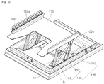
- FIG. 3 is a view illustrating a state in which a guide rail of the dish washing machine in accordance with an embodiment of the disclosure moves upward.
- FIG. 4 is a view illustrating the door of the dish washing machine in accordance with an embodiment of the disclosure.
- FIG. 5 is a view illustrating a state in which the guide rail of the dish washing machine in accordance with an embodiment of the disclosure is moved upward.
- baskets may include an upper basket and a lower basket.
- a basket refers to a lower basket.
- the dish washing machine 1 may include the body 10 with an open front, the washing tub 12 provided in the body 10, the basket 14b provided in the washing tub 12 to store dishes, and the door 11 configured to open or close the open front of the body 10.
- the door 11 may be configured to be pivotable about a rotating shaft provided at the bottom. A user may open the door 11 by pulling a handle (not shown) provided on the outside of the door 11. The door 11 may become open while a top swings downward.
- the door 11 may include at least one guide rail 100 which allows the basket 14b to be mounted on a rear surface 11a of the door 11 when the basket 14b is drawn out from the washing tub 12 while the door 11 is open and a lifting device 120 which lifts the basket 14b mounted on the rear surface 11a of the door 11 using the guide rail 100.
- the lifting device 120 may guide movement of the guide rail 100 to allow the guide rail 100 to move between a raised position and a lowered position.
- the rear surface 111 of the cover member 110 may form at least a part of the rear surface 11a of the door 11.
- the lifting device 120 when the lifting device 120 is in a lowered state, the lifting device 120 may be enclosed inside the door 11 and not exposed to outside. That is, when the lifting device 120 is enclosed inside the door 11, the lifting device may be covered by the cover member 110 not to be exposed to outside. Accordingly, when the door 11 is closed, the lifting device 120 may be separated from a washing space by the cover member 110. Accordingly, a dish washing machine in accordance with the concept of the disclosure may provide a lifting device having a space separate from a washing tub and a structure with no interference when the door 11 is closed. Through this, the lifting device 120 does not invade a washing space and washing water or garbage may be prevented from contaminating the lifting device 120. Also, the lifting device 120 below the cover member is not exposed to outside, and aesthetics improve.
- the basket 14b may be coupled with the guide rail 100. Also, when a user lifts the basket 14b coupled with the guide rail 100, the basket 14b may be moved upward with the guide rail 100 by the lifting device 120. The user may bend his or her back a little bit to load or unload dishes while the basket 14b is in a raised state.
- the basket 14b may include a plurality of rollers 15 at the bottom thereof.
- the basket 14b may smoothly move into or out of the washing tub 12 due to the rollers 15.
- the rollers 15 may be arranged in two rows on both sides at the bottom of the basket 14b, and the number of rollers 15 in each of the rows may be identical.
- the basket 14b may be stably supported by the rollers 15 arranged as such.
- the door 11 includes at least one guide rail 100 configured to raise and lower the basket 14b outward from a washing space, the lifting device 120 which moves the guide rail 100 upward, and the cover member 110 which covers the lifting device 120 when the lifting device 120 is enclosed inside the door 11.
- the guide rail 100 is provided in a shape corresponding to the rollers 15 of the basket 14b.
- the guide rail 100 defines a movement path on which the rollers 15 of the basket 14b roll and prevents the rollers 15 from deviating from the guide rail 100.
- the guide rail 100 may include a rail groove 100a which forms a path on which the rollers 15 roll and a guide wall 100b which controls the rollers 15 not to move in a direction perpendicular to the movement path of the rollers 15, that is, a width direction.
- the guide wall 100b is formed at a position for controlling the outer side of the rollers 15.
- the same effect may be provided even when the guide wall 100b is formed at a position for controlling the inner side of the rollers 15.
- an outer circumferential surface of a roller 25 is caved in toward a rotation center of the roller 25 and a guide rail 200 is formed in a protruding rib shape not to allow the roller 25 to lean left or right while the roller 25 is rolling (refer to FIGS. 25 and 26 ).
- a pair of guide rails 100 may be configured corresponding to the rollers 15 on left and right of the basket 14b.
- the rollers 15 are arranged in two rows, on which side the guide rail 100 is disposed is immaterial, whether left or right.
- the pair of guide rails 100 are disposed on both sides, while it is unnecessary that the guide rails 100 have the same shapes, at either of the guide rails 100, there may be no guide wall 100b or rail groove 100a.
- the lifting device 120 includes a link member 130 which supports the guide rail 100 when the guide rail 100 is separated from the rear surface of the door.
- a pivoting portion 130a may be provided at one end of the link member 130, and the link member 130 may pivot about the pivoting portion 130a in such a way that the guide rail 100 may move upward or downward.
- the guide rail 100 and the basket 14b may move upward or downward together.
- the link member 130 When the guide rail 100 is in a lowered state, the link member 130 may be disposed parallel to a longitudinal direction of the door 11, that is, a direction in which the rollers 15 of the basket 14b move and be enclosed inside the door 11. When the guide rail 100 moves upward, the link member 130 pivots about the pivoting portion 130a and is exposed outside the door. That is, depending on a pivoting angle of the link member 130, how high the guide rail 100 moves may become different.
- a pair of such link members 130 may be provided at one guide rail 100.
- the pair of link members 130 may include a first link member 131 and a second link member 132.
- Each of the link members 131 and 132 may be arranged in a row parallel to each other below the guide rail 100, and the first link member 131 and the second link member 132 may be arranged to at least partially overlap with each other.
- the link member 130 may be provided in a shape with a space therein.
- the first link member 131 may include a pair of side frames 131b and 131c which face each other and a connecting frame 131d which is connected to one of the pair of side frames 131b and 131c to form a cross section of the first link member 131 in an open rectangle shape.
- the second link member 132 may include a pair of side frames 132b and 132c which face each other and a connecting frame 132d which is connected to one of the pair of side frames 132b and 132c to form a cross section of the second link member 132 in an open rectangle shape.
- the connecting frames 131d and 132d of the pair of link members 131 and 132 are allowed to be arranged in a direction far from each other in such a way that the pair of side frames of one of the link members are disposed between the pair of side frames of the other link member when the guide rail 100 is enclosed inside the door.
- an inner space 133 of the link member which is defined by one side frame 131b and the connecting frame 131d of the one link member and one side frame 132c of the other link member 132 may be formed, and a link connecting member 140 may be disposed in the inner space 133 as follows.
- the link connecting member 140 is disposed to connect the first link member 131 with the second link member 132. Also, in order not to interfere with pivoting operations of the link members 131 and 132, one end 140a of the link connecting member 140 is pivotably coupled with the first link member 131, and another end 140b of the link connecting member 140 is pivotably coupled with the second link member 132.
- the one end 140a of the link connecting member 140 coupled with the link member 131 may be configured to have the same rotation shaft with the pivoting portion 131a of the link member 131.
- the inner space 133 is formed by the pair of link members 131 and 132, and the link connecting member 140 is disposed in the inner space 133 and surrounded by the pair of link members 131 and 132. As described above, volume occupied by the lifting device 120 may be minimized.
- the link connecting member 140 may be configured as an elastic body such as a spring. Through this configuration, force necessary for lifting the guide rail 100 may be reduced.
- the link connecting member 140 is formed as a spring
- the pair of link members 131 and 132 and the spring may be arranged parallel to the door 11.
- the spring is in a state in which length thereof is stretched, that is, in a biased state.
- distance between a connecting point between the spring and the first link member 131 and a connecting point between the second link member 132 and the spring becomes shorter. That is, the length of the spring becomes gradually shorter.
- elastic restoring force of the spring acts, and the force is in a direction of lifting the guide rail 100.
- the user may lift the basket 14b and the guide rail 100 using small force.
- the number, elastic coefficient, or length of such springs may be changed.
- the guide rail 100 is allowed to rapidly move upward, dishes loaded on the basket 14b mounted on the guide rail 100 may be shocked and damaged or separated from the basket 14b.
- FIG. 8 is an enlarged view of a part A of FIG. 5 .
- FIG. 9 is a view illustrating the inside of the door of the dish washing machine in accordance with an embodiment of the disclosure.
- FIG. 10 is an enlarged view illustrating a part B of FIG. 9 .
- the lifting device 120 may include a rotation stopper 160 which restricts the link member 131 from rotating by a certain angle or more. Limiting the rotation angle of the link member 131 is to limit a maximum raised height of the guide rail 100. This helps the basket 14b mounted on the guide rail 100 to move up to an optimal height for a user to comfortably and stably load dishes.
- the lifting device 120 of the dish washing machine in accordance with the embodiment may include a slowing device 150 which cooperates with the rotation stopper 160. Before describing an operation of the rotation stopper 160, the slowing device 150 will be described first.
- FIG. 11 is a view illustrating the slowing device of the dish washing machine in accordance with an embodiment of the disclosure.
- FIG. 12 is an exploded perspective view of the slowing device shown in FIG. 11 .
- the lifting device 120 may include at least one slowing device 150 for reducing moving-up speed or moving-down speed of the guide rail 100. That is, the slowing device 150 performs a function of preventing a shock from being applied to dishes loaded on the basket 14b by slowing speed of the guide rail 100 before the guide rail 100 on which the basket 14b is mounted stops at a highest position or a lowest position.
- the slowing device 150 may include an operating body 151, a body case 152 which accommodates at least a part of the operating body 151, a damping spring 153 configured to provide an elastic restoring force to the operating body 151, and a housing 154.
- Sliding protrusions 151a may be provided on both sides of the operating body 151, and sliding grooves 152a engaged with the sliding protrusions 151a may be provided at the body case 152.
- the sliding grooves 152a may be provided on both inner sides of the body case 152 along a longitudinal direction thereof. Accordingly, the operating body 151 may move forward and backward in the body case 152 by as much as a length of the body case 152.
- the sliding groove 152a may not be formed around the front portion of the body case 152 to restrict a movement range of the operating body 151.
- the body case 152 in which the operating body 151 is inserted may be mounted in the housing 154.
- the damping spring 153 is provided between the operating body 151 and the housing 154. Accordingly, a force greater than an elastic force of the damping spring 153 is necessary to move the operating body 151 backward.
- the operating body 151 moves backward and is inserted in the body case 152.
- the force becomes identical to the elastic force of the damping spring 153, the operating body 151 does not move backward.
- the force applied to the operating body 151 is removed, the operating body 151 moves forward again and protrudes due to the elastic restoring force of the damping spring 153.
- damping force provided by the operating body 151 is determined in accordance with a length by which the damping spring 153 is compressed.
- the slowing device 150 may include a structure capable of changing the length by which the damping spring 153 is compressed.
- a support 155 disposed opposite the operating body 151 with interposing the damping spring 153 therebetween and a damping control tab 156 which controls position of the support 155 along a movement direction of the operating body 151 are mounted in the housing 154 of the slowing device 150.
- a recess 155a which accommodates one end of the damping spring 153 and a screw hole 155b for being coupled with the damping control tab 156 are formed at the support 155.
- the damping control tab 156 is inserted in a through hole 154a formed at the housing 154 and is rotatably mounted on the housing 154.
- the damping control tab 156 may include a knob 156a which is a part gripped when the damping control tab 156 is rotated and a stem 156b which extends from the knob 156a and passes through the housing 154.
- a screw portion 156c with a screw thread formed thereon is formed at one end of the stem 156b to be coupled with the screw hole 155b of the support 155.
- the support 155 may be provided in an approximate rectangular parallelepiped shape. At least one surface of the support 155 is allowed to come into contact with an inner surface of the housing 154 in such a way that the support 155 does not rotate while the damping control tab 156 is rotated. Accordingly, when the knob 156a of the damping control tab 156 is gripped and rotated, the stem 156b rotates in such a way that a position of the support 155 screw-coupled with the stem 156b may be moved forward or backward. Accordingly, a distance between the support 155 and the operating body 151 becomes shorter or longer, and a length of the damping spring 153 disposed therebetween becomes shorter or longer. As the length of the damping spring 153 becomes shorter, since a force of biasing the operating body 151 toward a front of the body case 152 becomes greater, a damping force provided by the slowing device 150 becomes greater.
- FIG. 13 is a plan view illustrating the inside of the door of the dish washing machine in accordance with an embodiment of the disclosure.
- FIG. 14 is a view illustrating an operation of the slowing device of the dish washing machine in accordance with an embodiment of the disclosure.
- the slowing device 150 may be disposed to allow a longitudinal direction of the slowing device 150 to be on a line extending in a longitudinal direction of the link member 130. That is, the slowing device 150 may be disposed to allow the operating body 151 to move backward due to the rotation stopper 160 of the link member 131 when the guide rail 100 moves upward.
- the rotation stopper 160 and the operating body 151 may have a certain distance therebetween when the guide rail 100 is in a lowered state.
- the rotation stopper 160 and the operating body 151 may not be in contact with each other.
- the distance between the rotation stopper 160 and the operating body 151 gradually becomes shorter.
- the rotation stopper 160 and the operating body 151 come into contact with each other, and the rotation stopper 160 pressurizes the operating body 151 in a direction in which the operating body 151 moves backward.
- the damping spring 153 As the damping spring 153 is compressed by a force applied to the operating body 151, the damping spring 153 provides an elastic restoring force, that is, a damping force in a direction for moving the operating body 151 forward.
- the damping force provided by the operating body 151 is transferred to the rotation stopper 160 in such a way that a rotating speed of the link member 130 becomes reduced.
- the slowing device 150 reduces a moving-up speed of the guide rail 100 before the guide rail 100 arrives at the highest position. Simultaneously, the operating body 151 of the slowing device 150 comes into contact with the rotation stopper 160, thereby limiting rotation angle of the link member 130.
- the slowing device 150 reduces the moving-up speed of the guide rail 100 .
- the slowing device 150 may also be used for reducing the moving-down speed of the guide rail 100.
- a part of the link member 130 may be disposed to move the operating body 151 backward when the guide rail 100 moves downward.
- the slowing device 150 may be disposed to allow the longitudinal direction to be perpendicular to the longitudinal direction of the link member 130 to perform such function.
- a portion at which the operating body 151 is in contact with the link member 130 is formed to incline or to be rounded in such a way that the operating body 151 may move backward when the link member 130 applies the force from top to bottom.
- the slowing device 150 may prevent the guide rail 100 from rapidly moving downward. Since force greater than elastic force of the damping spring 153 is necessary to move the operating body 151 backward, the link member 130 moves the operating body 151 backward, and a rotating speed of the link member 130 is reduced. As the rotating speed of the link member 130 is reduced, the moving-down speed of the guide rail 100 also is reduced.
- FIG. 15 is a view illustrating the cover member of a dish washing machine in accordance with an embodiment of the disclosure.
- FIG. 16 is a view illustrating a state in which the guide rail moves upward in FIG. 15 .
- the cover member 110 may include a sealing portion 110a on an edge thereof to effectively prevent washing water or garbage from permeating into the lifting device 120.
- the sealing portion 110a is formed at the edge of the cover member 110 and seals a space between the cover member 110 and the rear surface of the door 11.
- FIG. 17 is a view of the door of the dish washing machine in accordance with an embodiment of the disclosure.
- FIG. 18 is a view illustrating a state in which the guide rail of the door moves upward in the dish washing machine of FIG. 17 .
- the pair of guide rails 100 may be provided, and the cover member may not be provided between the pair of guide rails 100. That is, the pair of guide rails 100 may be installed separately from each other.
- Each of the guide rails 100 may be supported by the link members and may move upward or downward as the first link member 131 and the second link member 132 pivot. Since a detailed configuration of the lifting device is identical to that shown in FIGS. 5 to 7 , a repeated description will be omitted.
- a dish washing machine with a simplified structure, reduced number of materials, and reduced manufacturing cost may be provided by omitting the cover member.
- FIG. 19 is a view illustrating a state in which the door of a dish washing machine according to an embodiment, which is not part of the present invention, is open.
- FIG. 20 is a view illustrating a state in which the guide rail of the dish washing machine of FIG. 19 is moved upward.
- FIG. 21 is a view illustrating the guide rail and a lifting device of the dish washing machine of FIG. 19 .
- a dish washing machine 2 may include the body 10 with an open front, the washing tub 12 provided in the body 10, the basket 14b provided in the washing tub 12 to store dishes, and the door 11 configured to open or close the open front of the body 10.
- the door 11 may be configured to be pivotable about a rotating shaft provided at the bottom. A user may open the door 11 by pulling a handle (not shown) provided on the outside of the door 11. The door 11 may become opened while the top swings downward.
- the door 11 may include at least one guide rail 100 which allows the basket 14b to be mounted on a rear surface of the door 11 when the basket 14b is drawn out from the washing tub 12 while the door 11 is open and a lifting device 220 which lifts the basket 14b mounted on the rear surface of the door 11 using the guide rail 100.
- the lifting device 220 may include a link member 230 which supports the guide rail 100 when the guide rail 100 is spaced apart from the rear surface of the door 11, a damper 240, and a lifting device case 250 which accommodates the link member 230 and the damper 240.
- a pair of such link members 230 may be provided at one guide rail 100.
- the pair of link members 230 may include a first link member 231 and a second link member 232.
- Each of the link members 231 and 232 may be arranged in a row parallel to each other below the guide rail 100.
- Pivoting portions 231a and 232a may be provided at one end of the link member 230, and the link member 230 may pivot about the pivoting portions 231a and 232a from the door 11 in such a way that the guide rail 100 may move upward or downward.
- the guide rail 100 and the basket 14b may move upward or downward together.
- the lifting device 220 When the lifting device 220 is in a lowered state, the lifting device 220 is enclosed inside the door 11 and not exposed outward. That is, when the lifting device 220 is enclosed inside the door 11, the lifting device 220 may be covered by the cover member 110 not to be exposed to outside. Accordingly, when the door 11 is closed, the lifting device 220 may be moved away from a washing space by the cover member 110. Accordingly, the dish washing machine 2 may provide a lifting device having a space separate from a washing tub and a structure with no interference, when the door 11 is closed.
- a first pivoting shaft 251 providing a rotation center to allow the first link member 231 to rotate and a second pivoting shaft 252 providing a rotation center to allow the second link member 232 to rotate may be provided at one side of the lifting device case 250.
- a damper pivoting shaft 253 providing a rotation center to allow the damper 240 to rotate may be provided at another side of the lifting device case 250.
- the first pivoting shaft 251 and the second pivoting shaft 252 are arranged corresponding to the pivoting portions 231a and 232a of the link member 230.
- damper pivoting portion 240a is provided at one end of the damper 240, the damper 240 pivots about the damper pivoting portion 240a from the door, and the damper pivoting shaft 253 is disposed corresponding to the damper pivoting portion 240a.
- the lifting device case 250 may include a rotation stopper 260 at one side thereof which restricts the link member 230 from rotating by a certain angle or more. Limiting the rotation angle of the link member 230 is to limit a maximal raised height of the guide rail 100. This helps the basket 14b mounted on the guide rail 100 in moving upward to an optimal height for a user to comfortably and stably load dishes.
- the first link member 231 is not allowed to rotate by a certain angle or more. This is because the rotation stopper 260 blocks rotation of the first link member 231 when the first link member 231 comes into contact with the rotation stopper 260.
- a position and a structure of the rotation stopper 260 are not limited to an example shown in FIG. 21 and may be modified into another structure configured to prevent rotation of a link member.
- the link member 230 and the damper 240 may be arranged in the lifting device case 250.
- one end of the damper 240 may be connected to be pivotable about the damper pivoting shaft 253 provided at the lifting device case 250, and another end may be pivotably connected to one side of the second link member 232.
- the damper 240 may be provided to have a variable length. That is, the length of the damper 240 is variable and a force is necessary to increase or decrease the length of the damper 240 due to properties thereof. In other words, the damper 240 is changeable in length, but the length thereof does not rapidly change due to the properties of the damper 240. Due to the properties of the damper 240 described above, unnecessary force may be reduced and a moving-down speed of the guide rail 100 may be reduced when the guide rail 100 is moved upward.
- the damper 240 may accommodate oil therein.
- the oil in the damper 240 may prevent a rapid change in the length of the damper 240.
- a spring (not shown) may be installed in the damper 240.
- the spring in the damper 240 may be configured to accumulate elastic force when the length of the damper 240 becomes shorter and to apply elastic restoring force in a direction in which the length of the damper 240 becomes longer.
- the damper 240 When the guide rail 100 is in a lowered state, the damper 240 may be disposed parallel to a longitudinal direction of the door 11, that is, a direction in which the rollers 15 of the basket 14b move and be enclosed.
- the length of the damper 240 may be small.
- the link member 230 pivots about the pivoting portions 231a and 232a, and the damper 240 connected to a pivoting member becomes longer.
- the damper 240 may apply pushing force to the link member 230 and accordingly force necessary for lifting the guide rail 100 may be reduced.
- the damper 240 when the user tries to lift the guide rail 100 too rapidly, the damper 240 applies pulling force to the link member 230 due to properties thereof. Accordingly, in this case, the guide rail 100 may be prevented from rapidly moving up.
- the damper 240 may be in a state in which the length thereof becomes longer when the guide rail 100 is in a raised state. As the guide rail 100 starts moving downward, the link member 230 pivots about the pivoting portions 231a and 232a and the damper 240 connected to the link member 230 becomes shorter.
- the damper 240 withstands weight of the basket 14b including dishes and reduces moving-down speed of the guide rail 100. That is, the damper 240 supports weight of the guide rail 100 on which the basket 14b is mounted. Through this, the user is able to lift the basket 14b without exerting a great force, and also the lifting device 220 may be smoothly and stably driven even when dishes are loaded in the basket 14b.
- FIG. 22 is a view of the door of the dish washing machine of FIG. 19 .
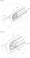
- FIG. 23 is an enlarged view illustrating part C of FIG. 22 .
- FIG. 24 is an enlarged view of part C of FIG. 22 to transparently show the roller.
- the basket 14b may include a plurality of such rollers 15 at the bottom thereof.
- the basket 14b may smoothly move into or out of the washing tub 12 due to the rollers 15.
- the guide rail 100 may be formed in a shape corresponding to the rollers 15 to allow the rollers 15 to be inserted and guided. As shown in FIG. 22 , the guide rail 100 may include an open one end 102 and another closed end 104. The rollers 15 may be inserted through the open one end 102 of the guide rail 100 and may move toward the other closed end 104.
- the guide rail 100 may include a roller stopper 101 provided to fix the rollers 15 when the rollers 15 are inserted to be close to the other closed end.
- the roller stopper 101 may be provided at the other closed end of the guide rail 100.
- the roller stopper 101 may be provided in a holding protrusion shape.
- an outer circumferential surface of the roller 25 is caved in toward the rotation center of the roller 25 and the guide rail 200 is formed in a protruding rib shape not to allow the roller 25 to lean left or right while the roller 25 is rolling.
- the roller 25 may include a depressed portion 25a which is a center of an outer circumferential surface thereof and depressed toward the rotation center of the roller 25 and a protruding portion 25b which is both sides of the depressed portion 25a and forms the outer circumferential surface of the roller 25.
- the guide rail 200 may include a rail protruding portion 200a which protrudes corresponding to the depressed portion 25a of the roller 25 and a rail bottom portion 200b which is formed on both sides of the rail protruding portion 200a and is in contact with the protruding portion 25b of the roller 25.
- the rail protruding portion 200a may be inserted in the depressed portion 25a of the roller 25, and the roller 25 may be guided along the rail protruding portion 200a. Through this, without forming a guide wall, the roller 25 may not lean left or right.
Landscapes
- Engineering & Computer Science (AREA)
- Water Supply & Treatment (AREA)
- Washing And Drying Of Tableware (AREA)
Description
- Embodiments of the disclosure relate to a dish washing machine, and more particularly, to a dish washing machine which removes inconvenience of using a lower basket.
- Generally, a dish washing machine is an apparatus which jets washing water at a high pressure to dishes to wash, and generally a preliminary washing operation, a main washing operation, a rinsing operation, and a drying operation are performed. In the preliminary washing operation, garbage on dishes is removed by jetting washing water without a detergent. In the main washing operation, a detergent is added by a detergent supply device simultaneously with jetting washing water for washing dishes.
- Meanwhile, baskets for loading dishes to be washed are installed at the top and bottom in a dish washing machine, and an upper basket and a lower basket may be independently inserted into or drawn out from the dish washing machine.
- Generally, the lower basket of the dish washing machine is large and heavy and used for washing a large amount of dishes. Here, there is an inconvenience for a user to repeatedly fold and unfold his or her back by about 90 degrees to load and unload dishes.
-
KR 10-0220731 B1 -
US 2008/0018215 A1 discloses A refrigerator including a cabinet within which is arranged an upper fresh food compartment and a lower freezer compartment, wherein a freezer basket is slidingly supported in the freezer compartment, preferably for concurrent movement with a freezer door and wherein the freezer basket is coupled to a lifting mechanism that selectively shifts the freezer basket from a first or lowered position to a second or raised position in order to facilitate removal of items from the freezer basket. -
US 2008/0129168 A1 discloses a rack support system for a lower rack in a dishwasher including a frame configured to support the lower rack, and a linkage system coupling the frame to a side wall of the tub such that the lower rack is movable between a retracted position within the wash chamber and an extended position wherein the lower rack extends from the wash chamber, wherein the lower rack is movable within a range between a lowered position and an elevated position with the lower rack extended from the wash chamber. -
US 5,115,822 A discloses a dishwasher lower basket assembly including a dish holding basket and a lift mechanism for elevating the basket above the dishwasher door to a position adjacent the upper dish holding basket of the dishwasher. - Therefore, it is an aspect of the disclosure to provide a dish washing machine including a lifting device for moving a lower basket up and down to remove inconvenience of using the lower basket of the dish washing machine.
- It is another aspect of the disclosure to provide a dish washing machine including an improved lifting device that does not invade a washing space.
- It is still another aspect of the disclosure to provide a dish washing machine which reduces garbage blockages which may occur at a lifting device during washing and draining.
- In accordance with an aspect of the disclosure, a dish washing machine may include a washing tub with an open front, a basket configured to be inserted into or drawn out from the washing tub through the open front of the washing tub, a door configured to open or close the open front of the washing tub, at least one guide rail configured to mount the basket on the door when the basket is drawn out from the washing tub while the door is open, and a lifting device configured to raise and lower the at least one guide rail between a raised position and a lowered position respectively, wherein the lifting device includes at least one link member pivotably provided at the door, wherein the at least one link member includes a pair of link members arranged to at least partially overlap each other when the at least one guide rail is in the lowered Position, wherein the lifting device further includes a link connecting member connecting the pair of link members which is accommodated in an inner space provided between the pair of link members arranged to overlap each her, wherein the link connecting member is surrounded by the pair of link members.
- The lifting device may be enclosed inside the door when the guide rail is in the lowered position and may be exposed outside the door when the guide rail is in the raised position.
- The lifting device may include at least one elastic member configured to provide an elastic restoring force in a direction in which the guide rail moves upward.
- The lifting device may further include the pair of link members arranged parallel to each other to support the guide rail, and the at least one elastic member may be disposed between the pair of link members.
- The door may further include at least one slowing device configured to reduce at least one of a speed at which the at least one guide rail is raised and a speed at which the at least one guide rail is lowered.
- The slowing device may include an operating body configured to reciprocate and to apply a force to the lifting device and a damping spring may provide an elastic restoring force to the operating body.
- The at least one link member may include a rotation stopper configured to limit a rotation angle of the at least one link member.
- The basket may include a plurality of rollers at a bottom thereof, and the at least one guide rail may include a rail groove on which the plurality of rollers are mounted.
- The at least one guide rail may further include a roller stopper configured to limit a movement of the plurality of rollers.
- The at least one guide rail may include a pair of guide rails arranged paralled to one another.
- The dish washing machine may further include a cover member configured to cover the lifting device when the at least one guide rail is in the lowered position.
- The cover member may include a sealing portion configured to prevent washing water from permeating the lifting device when the cover member covers the lifting device.
- In accordance with an aspect of the disclosure, a dish washing machine may include a washing tub having an open portion, a basket and a door configured to open or close the open portion of the washing tub, the door may include a front surface that faces away from the open the open portion of the washing tub when the door is closed, and a rear surface that faces away from the open portion of the washing tub when the door is closed, wherein a distance between at least a portion of the rear surface of the door and the front surface of the door is changeable so as to raise or lower the basket when the basket is drawn out from the washing tub.
- The door may include at least one guide rail disposed on the rear surface of the door and configured to guide the basket when the basket is drawn out from the washing tub and a lifting device configured to raise and lower the at least one guide rail.
- The lifting device may be accommodated between the front surface and the rear surface of the door when the at least one guide rail is in a lowered position.
- The door may further include a cover member configured to cover the lifting device when the at least one guide rail is in the lowered position.
- The lifting device may further include a damper disposed below the at least one guide rail and configured to provide a damping force in a direction for reducing a movement speed of the at least one guide rail.
- As is apparent from the above description, a dish washing machine in accordance with one or more embodiments of the disclosure may increase convenience for a user when loading dishes in or unloading dishes from a lower basket.
- A dish washing machine in accordance with one or more embodiments of the disclosure may reduce a space occupied by a lifting device, thus not reducing washing space. Also, a dish washing machine in accordance with one or more embodiments of the disclosure may reduce a garbage blocking phenomenon which occurs during washing or draining.
- A dish washing machine in accordance with one or more embodiments of the disclosure may include a lifting device for moving a lower basket up and down using a small force.
-
-
Fig. 1 is a cross-sectional view of a dish washing machine in accordance with an embodiment of the disclosure; -
Fig. 2 is a view illustrating a state in which a door of the dish washing machine is opened in accordance with an embodiment of the disclosure; -
Fig. 3 is a view illustrating a state in which a guide rail of the dish washing machine moves upward in accordance with an embodiment of the disclosure; -
Fig. 4 is a view illustrating the door of the dish washing in accordance with an embodiment of the disclosure; -
Fig. 5 is a view illustrating a state in which the guide rail of the dish washing is moved upward in accordance with an embodiment of the disclosure; -
Fig. 6 is a view illustrating a link member and a link connecting member of the dish washing machine in accordance with an embodiment of the disclosure; -
Fig. 7 is a view illustrating a state in which the link member and the link connecting member of the dish washing machine are arranged to overlap each other in accordance with an embodiment of the disclosure; -
Fig. 8 is an enlarged view of a part A ofFig. 5 ; -
Fig. 9 is a view illustrating the inside of the door of the dish washing machine in accordance with an embodiment of the disclosure; -
Fig. 10 is an enlarged view illustrating a part B ofFIG. 9 ; -
Fig. 11 is a view illustrating the slowing device of the dish washing machine in accordance with an embodiment of the disclosure; -
Fig. 12 is an exploded perspective view of the slowing device shown inFIG. 11 ; -
Fig. 13 is a plan view illustrating the inside of the door of the dish washing machine in accordance with an embodiment of the disclosure; -
Fig. 14 is a view illustrating an operation of the slowing device of the dish washing machine in accordance with an embodiment of the disclosure; -
Fig. 15 is a view illustrating the cover member of a dish washing machine in accordance with an embodiment of the disclosure; -
Fig. 16 is a view illustrating a state in which the guide rail moves upward inFIG. 15 ; -
Fig. 17 is a view of the door of the dish washing machine in accordance with an embodiment of the disclosure; -
Fig. 18 is a view illustrating a state in which the guide rail of the door moves upward in the dish washing machine ofFIG. 17 ; -
Fig. 19 is a view illustrating a state in which the door of a dish washing machine is open in accordance with an embodiment, which is not part of the present invention; -
Fig. 20 is a view illustrating a state in which the guide rail of the dish washing machine ofFIG. 19 is moved upward; -
Fig. 21 is a view illustrating the guide rail and a lifting device of the dish washing machine ofFIG. 19 ; -
Fig. 22 is a view of the door of the dish washing machine ofFIG. 19 ; -
Fig. 23 is an enlarged view illustrating part C ofFIG. 22 ; -
Fig. 24 is an enlarged view of part C ofFIG. 22 to transparently show the roller; -
Fig. 25 is a view of a roller and a guide rail of the dish washing machine in accordance with an embodiment of the disclosure; -
Fig. 26 is a cross-sectional view of the roller and the guide rail ofFig. 25 ; - Reference will now be made in detail to example embodiments which are illustrated in the accompanying drawings, wherein like reference numerals refer to like elements throughout. The embodiments are described below to explain the disclosure by referring to the figures.
- Hereinafter, exemplary embodiments of the disclosure will be described in detail. Meanwhile, the terms "front end", "rear end", "top", "bottom", "top end", "bottom end", etc. used herein are defined based on the drawings, and shapes and positions of components are not limited thereto.
-
FIG. 1 is a cross-sectional view of a dish washing machine in accordance with an embodiment of the disclosure. - A
dish washing machine 1 may include abody 10 which forms an exterior, awashing tub 12 provided in thebody 10,baskets washing tub 12 to store dishes, asump 20 which collects and stores washing water, andjet units - The
washing tub 12 is formed in an approximate box shape and has an open front for putting in or taking out dishes. The open front of thewashing tub 12 may be opened and closed by adoor 11. Thedoors 11 may be pivotably coupled with thebody 10. - The
baskets upper basket 14a and alower basket 14b. Theupper basket 14a may be supported by anupper rail 13a, and thelower basket 14b may be supported by alower rail 13b. Theupper basket 14a and thelower basket 14b may be configured to be slidable forward and backward in thewashing tub 12 due to theupper rail 13a and thelower rail 13b. - Water stored in the
sump 20 may include awashing pump 21 which pumps the stored water to thejet units washing pump 21 may be supplied to afirst jet unit 41 and asecond jet unit 42 through afirst supply pipe 31 and to athird jet unit 43 through asecond supply pipe 32. - Also, a
heater 16 for heating washing water and adrain pump 22 for draining washing water may be provided at a bottom of thewashing tub 12. - Meanwhile, as shown in
FIG. 1 , thefirst jet unit 41 may be provided above theupper basket 14a, thesecond jet unit 42 may be provided between theupper basket 14a and thelower basket 14b, and thethird jet unit 43 may be provided below thelower basket 14b. - Also, the
first jet unit 41 may be configured to rotate about arotating shaft 41a, and thesecond jet unit 42 may be configured to rotate about arotating shaft 42a. - The
first jet unit 41 may jet washing water toward dishes stored in theupper basket 14a, and thesecond jet unit 42 may jet washing water toward dishes stored in thelower basket 14b. - Meanwhile, the
third jet unit 43 may be provided at one side of thewashing tub 12, unlike thefirst jet unit 41 and thesecond jet unit 42. Thethird jet unit 43 may jet washing water in an approximate horizontal direction. Accordingly, the washing water jetted by thethird jet unit 43 may be not directly jetted toward the dishes. - The
third jet unit 43 may include anozzle 44 which jets washing water. Thenozzles 44 may be arranged in a row, at a certain regular spacing approximately from one side of thewashing tub 12 to the opposite side. - The washing water horizontally jetted from the
nozzle 44 of thethird jet unit 43 may be deflected by a deflectingassembly 60 disposed in thewashing tub 12 and may move toward dishes stored in thelower basket 14b. The deflectingassembly 60 is configured to be fastened to ajet rail 62 by aholder 64 and to be movable along thejet rail 62. -
FIG. 2 is a view illustrating a state in which the door of the dish washing machine in accordance with an embodiment of the disclosure is open.FIG. 3 is a view illustrating a state in which a guide rail of the dish washing machine in accordance with an embodiment of the disclosure moves upward.FIG. 4 is a view illustrating the door of the dish washing machine in accordance with an embodiment of the disclosure.FIG. 5 is a view illustrating a state in which the guide rail of the dish washing machine in accordance with an embodiment of the disclosure is moved upward. - As described above, baskets may include an upper basket and a lower basket. Hereinafter, a basket refers to a lower basket.
- As is apparent from
FIGS. 2 and3 , thedish washing machine 1 may include thebody 10 with an open front, thewashing tub 12 provided in thebody 10, thebasket 14b provided in thewashing tub 12 to store dishes, and thedoor 11 configured to open or close the open front of thebody 10. - The
door 11 may be configured to be pivotable about a rotating shaft provided at the bottom. A user may open thedoor 11 by pulling a handle (not shown) provided on the outside of thedoor 11. Thedoor 11 may become open while a top swings downward. - The
door 11 may include at least oneguide rail 100 which allows thebasket 14b to be mounted on arear surface 11a of thedoor 11 when thebasket 14b is drawn out from thewashing tub 12 while thedoor 11 is open and alifting device 120 which lifts thebasket 14b mounted on therear surface 11a of thedoor 11 using theguide rail 100. Thelifting device 120 may guide movement of theguide rail 100 to allow theguide rail 100 to move between a raised position and a lowered position. - When a
cover member 110 is installed at thedoor 11, therear surface 111 of thecover member 110 may form at least a part of therear surface 11a of thedoor 11. - As shown in
FIGS. 2 and4 , when thelifting device 120 is in a lowered state, thelifting device 120 may be enclosed inside thedoor 11 and not exposed to outside. That is, when thelifting device 120 is enclosed inside thedoor 11, the lifting device may be covered by thecover member 110 not to be exposed to outside. Accordingly, when thedoor 11 is closed, thelifting device 120 may be separated from a washing space by thecover member 110. Accordingly, a dish washing machine in accordance with the concept of the disclosure may provide a lifting device having a space separate from a washing tub and a structure with no interference when thedoor 11 is closed. Through this, thelifting device 120 does not invade a washing space and washing water or garbage may be prevented from contaminating thelifting device 120. Also, thelifting device 120 below the cover member is not exposed to outside, and aesthetics improve. - As shown in
FIG. 3 , thebasket 14b may be coupled with theguide rail 100. Also, when a user lifts thebasket 14b coupled with theguide rail 100, thebasket 14b may be moved upward with theguide rail 100 by thelifting device 120. The user may bend his or her back a little bit to load or unload dishes while thebasket 14b is in a raised state. - The
basket 14b may include a plurality ofrollers 15 at the bottom thereof. Thebasket 14b may smoothly move into or out of thewashing tub 12 due to therollers 15. As shown inFIGS. 2 and3 , therollers 15 may be arranged in two rows on both sides at the bottom of thebasket 14b, and the number ofrollers 15 in each of the rows may be identical. Thebasket 14b may be stably supported by therollers 15 arranged as such. - As shown in
FIG. 4 , thedoor 11 includes at least oneguide rail 100 configured to raise and lower thebasket 14b outward from a washing space, thelifting device 120 which moves theguide rail 100 upward, and thecover member 110 which covers thelifting device 120 when thelifting device 120 is enclosed inside thedoor 11. Theguide rail 100 is provided in a shape corresponding to therollers 15 of thebasket 14b. Theguide rail 100 defines a movement path on which therollers 15 of thebasket 14b roll and prevents therollers 15 from deviating from theguide rail 100. For this, theguide rail 100 may include arail groove 100a which forms a path on which therollers 15 roll and aguide wall 100b which controls therollers 15 not to move in a direction perpendicular to the movement path of therollers 15, that is, a width direction. In the embodiment, theguide wall 100b is formed at a position for controlling the outer side of therollers 15. However, the same effect may be provided even when theguide wall 100b is formed at a position for controlling the inner side of therollers 15. - As a modified structure thereof, an outer circumferential surface of a
roller 25 is caved in toward a rotation center of theroller 25 and aguide rail 200 is formed in a protruding rib shape not to allow theroller 25 to lean left or right while theroller 25 is rolling (refer toFIGS. 25 and 26 ). - Also, to stably support the
basket 14b, a pair ofguide rails 100 may be configured corresponding to therollers 15 on left and right of thebasket 14b. However, even though therollers 15 are arranged in two rows, on which side theguide rail 100 is disposed is immaterial, whether left or right. Also, when the pair ofguide rails 100 are disposed on both sides, while it is unnecessary that theguide rails 100 have the same shapes, at either of theguide rails 100, there may be noguide wall 100b orrail groove 100a. - As shown in
FIGS. 5 to 7 , thelifting device 120 includes alink member 130 which supports theguide rail 100 when theguide rail 100 is separated from the rear surface of the door. A pivotingportion 130a may be provided at one end of thelink member 130, and thelink member 130 may pivot about the pivotingportion 130a in such a way that theguide rail 100 may move upward or downward. When thebasket 14b is mounted on theguide rail 100, theguide rail 100 and thebasket 14b may move upward or downward together. - When the
guide rail 100 is in a lowered state, thelink member 130 may be disposed parallel to a longitudinal direction of thedoor 11, that is, a direction in which therollers 15 of thebasket 14b move and be enclosed inside thedoor 11. When theguide rail 100 moves upward, thelink member 130 pivots about the pivotingportion 130a and is exposed outside the door. That is, depending on a pivoting angle of thelink member 130, how high theguide rail 100 moves may become different. - A pair of
such link members 130 may be provided at oneguide rail 100. In this case, the pair oflink members 130 may include afirst link member 131 and asecond link member 132. Each of thelink members guide rail 100, and thefirst link member 131 and thesecond link member 132 may be arranged to at least partially overlap with each other. - Also, the
link member 130 may be provided in a shape with a space therein. For example, thefirst link member 131 may include a pair of side frames 131b and 131c which face each other and a connectingframe 131d which is connected to one of the pair of side frames 131b and 131c to form a cross section of thefirst link member 131 in an open rectangle shape. Similarly, thesecond link member 132 may include a pair of side frames 132b and 132c which face each other and a connectingframe 132d which is connected to one of the pair of side frames 132b and 132c to form a cross section of thesecond link member 132 in an open rectangle shape. - Here, the connecting
frames link members guide rail 100 is enclosed inside the door. As described above, as thelink members inner space 133 of the link member which is defined by oneside frame 131b and the connectingframe 131d of the one link member and oneside frame 132c of theother link member 132 may be formed, and alink connecting member 140 may be disposed in theinner space 133 as follows. - The
link connecting member 140 is disposed to connect thefirst link member 131 with thesecond link member 132. Also, in order not to interfere with pivoting operations of thelink members end 140a of thelink connecting member 140 is pivotably coupled with thefirst link member 131, and anotherend 140b of thelink connecting member 140 is pivotably coupled with thesecond link member 132. Here, the oneend 140a of thelink connecting member 140 coupled with thelink member 131 may be configured to have the same rotation shaft with the pivotingportion 131a of thelink member 131. As described above, while theguide rail 100 is enclosed inside the door, theinner space 133 is formed by the pair oflink members link connecting member 140 is disposed in theinner space 133 and surrounded by the pair oflink members lifting device 120 may be minimized. - The
link connecting member 140 may be configured as an elastic body such as a spring. Through this configuration, force necessary for lifting theguide rail 100 may be reduced. - Hereinafter, an example in which the
link connecting member 140 is formed as a spring will be described. When theguide rail 100 is in a lowered state, the pair oflink members door 11. Here, the spring is in a state in which length thereof is stretched, that is, in a biased state. When theguide rail 100 starts moving upward, distance between a connecting point between the spring and thefirst link member 131 and a connecting point between thesecond link member 132 and the spring becomes shorter. That is, the length of the spring becomes gradually shorter. Here, elastic restoring force of the spring acts, and the force is in a direction of lifting theguide rail 100. Particularly, when thebasket 14b on which dishes are loaded is mounted on theguide rail 100, the user may lift thebasket 14b and theguide rail 100 using small force. To further reduce force necessary for lifting theguide rail 100, the number, elastic coefficient, or length of such springs may be changed. However, when the elastic force of the spring becomes too strong, theguide rail 100 is allowed to rapidly move upward, dishes loaded on thebasket 14b mounted on theguide rail 100 may be shocked and damaged or separated from thebasket 14b. -
FIG. 8 is an enlarged view of a part A ofFIG. 5 .FIG. 9 is a view illustrating the inside of the door of the dish washing machine in accordance with an embodiment of the disclosure.FIG. 10 is an enlarged view illustrating a part B ofFIG. 9 . - The
lifting device 120 may include arotation stopper 160 which restricts thelink member 131 from rotating by a certain angle or more. Limiting the rotation angle of thelink member 131 is to limit a maximum raised height of theguide rail 100. This helps thebasket 14b mounted on theguide rail 100 to move up to an optimal height for a user to comfortably and stably load dishes. Thelifting device 120 of the dish washing machine in accordance with the embodiment may include a slowingdevice 150 which cooperates with therotation stopper 160. Before describing an operation of therotation stopper 160, the slowingdevice 150 will be described first. -
FIG. 11 is a view illustrating the slowing device of the dish washing machine in accordance with an embodiment of the disclosure.FIG. 12 is an exploded perspective view of the slowing device shown inFIG. 11 . - The
lifting device 120 may include at least oneslowing device 150 for reducing moving-up speed or moving-down speed of theguide rail 100. That is, the slowingdevice 150 performs a function of preventing a shock from being applied to dishes loaded on thebasket 14b by slowing speed of theguide rail 100 before theguide rail 100 on which thebasket 14b is mounted stops at a highest position or a lowest position. - As shown in
FIGS. 11 and12 , the slowingdevice 150 may include anoperating body 151, abody case 152 which accommodates at least a part of the operatingbody 151, a dampingspring 153 configured to provide an elastic restoring force to theoperating body 151, and ahousing 154. Sliding protrusions 151a may be provided on both sides of the operatingbody 151, and slidinggrooves 152a engaged with the sliding protrusions 151a may be provided at thebody case 152. The slidinggrooves 152a may be provided on both inner sides of thebody case 152 along a longitudinal direction thereof. Accordingly, the operatingbody 151 may move forward and backward in thebody case 152 by as much as a length of thebody case 152. Here, to prevent theoperating body 151 from deviating from thebody case 152 through an open front portion of thebody case 152, the slidinggroove 152a may not be formed around the front portion of thebody case 152 to restrict a movement range of the operatingbody 151. - The
body case 152 in which theoperating body 151 is inserted may be mounted in thehousing 154. Here, the dampingspring 153 is provided between the operatingbody 151 and thehousing 154. Accordingly, a force greater than an elastic force of the dampingspring 153 is necessary to move theoperating body 151 backward. When a force is applied to theoperating body 151, the operatingbody 151 moves backward and is inserted in thebody case 152. When the force becomes identical to the elastic force of the dampingspring 153, the operatingbody 151 does not move backward. When the force applied to theoperating body 151 is removed, the operatingbody 151 moves forward again and protrudes due to the elastic restoring force of the dampingspring 153. Accordingly, damping force provided by the operatingbody 151 is determined in accordance with a length by which the dampingspring 153 is compressed. Here, in the embodiment, the slowingdevice 150 may include a structure capable of changing the length by which the dampingspring 153 is compressed. - As shown in
FIG. 12 , asupport 155 disposed opposite the operatingbody 151 with interposing the dampingspring 153 therebetween and a dampingcontrol tab 156 which controls position of thesupport 155 along a movement direction of the operatingbody 151 are mounted in thehousing 154 of the slowingdevice 150. Arecess 155a which accommodates one end of the dampingspring 153 and ascrew hole 155b for being coupled with the dampingcontrol tab 156 are formed at thesupport 155. The dampingcontrol tab 156 is inserted in a throughhole 154a formed at thehousing 154 and is rotatably mounted on thehousing 154. The dampingcontrol tab 156 may include aknob 156a which is a part gripped when the dampingcontrol tab 156 is rotated and astem 156b which extends from theknob 156a and passes through thehousing 154. Ascrew portion 156c with a screw thread formed thereon is formed at one end of thestem 156b to be coupled with thescrew hole 155b of thesupport 155. - Meanwhile, the
support 155 may be provided in an approximate rectangular parallelepiped shape. At least one surface of thesupport 155 is allowed to come into contact with an inner surface of thehousing 154 in such a way that thesupport 155 does not rotate while the dampingcontrol tab 156 is rotated. Accordingly, when theknob 156a of the dampingcontrol tab 156 is gripped and rotated, thestem 156b rotates in such a way that a position of thesupport 155 screw-coupled with thestem 156b may be moved forward or backward. Accordingly, a distance between thesupport 155 and theoperating body 151 becomes shorter or longer, and a length of the dampingspring 153 disposed therebetween becomes shorter or longer. As the length of the dampingspring 153 becomes shorter, since a force of biasing the operatingbody 151 toward a front of thebody case 152 becomes greater, a damping force provided by the slowingdevice 150 becomes greater. -
FIG. 13 is a plan view illustrating the inside of the door of the dish washing machine in accordance with an embodiment of the disclosure.FIG. 14 is a view illustrating an operation of the slowing device of the dish washing machine in accordance with an embodiment of the disclosure. - Hereinafter, operations of the slowing
device 150 and therotation stopper 160 in the dish washing machine in accordance with an embodiment of the disclosure will be described. - In the embodiment, the slowing
device 150 may be disposed to allow a longitudinal direction of the slowingdevice 150 to be on a line extending in a longitudinal direction of thelink member 130. That is, the slowingdevice 150 may be disposed to allow theoperating body 151 to move backward due to therotation stopper 160 of thelink member 131 when theguide rail 100 moves upward. - As shown in
FIGS. 8 and10 , therotation stopper 160 and theoperating body 151 may have a certain distance therebetween when theguide rail 100 is in a lowered state. In other words, when thelink members door 11, therotation stopper 160 and theoperating body 151 may not be in contact with each other. When theguide rail 100 is lifted and thelink members rotation stopper 160 and theoperating body 151 gradually becomes shorter. As thelink members rotation stopper 160 and theoperating body 151 come into contact with each other, and therotation stopper 160 pressurizes the operatingbody 151 in a direction in which theoperating body 151 moves backward. Meanwhile, as the dampingspring 153 is compressed by a force applied to theoperating body 151, the dampingspring 153 provides an elastic restoring force, that is, a damping force in a direction for moving the operatingbody 151 forward. The damping force provided by the operatingbody 151 is transferred to therotation stopper 160 in such a way that a rotating speed of thelink member 130 becomes reduced. Through these operations, the slowingdevice 150 reduces a moving-up speed of theguide rail 100 before theguide rail 100 arrives at the highest position. Simultaneously, the operatingbody 151 of the slowingdevice 150 comes into contact with therotation stopper 160, thereby limiting rotation angle of thelink member 130. - In the above, an example in which the
slowing device 150 reduces the moving-up speed of theguide rail 100 has been described. However, independently from the example described above, the slowingdevice 150 may also be used for reducing the moving-down speed of theguide rail 100. In this case, contrary to the embodiment in which theoperating body 151 of the slowingdevice 150 moves backward as theguide rail 100 moves upward, a part of thelink member 130 may be disposed to move theoperating body 151 backward when theguide rail 100 moves downward. In the embodiment, the slowingdevice 150 may be disposed to allow the longitudinal direction to be perpendicular to the longitudinal direction of thelink member 130 to perform such function. - As shown in
FIG. 14 , when theguide rail 100 is in a raised state, thelink member 130 does not come into contact with the slowingdevice 150. When theguide rail 100 is pushed downward and thelink member 130 starts rotating, the distance between thelink member 130 and theoperating body 151 gradually becomes shorter. As thelink member 130 continues rotating, thelink member 130 and theoperating body 151 come into contact with each other, and thelink member 130 moves the operatingbody 151 backward. Here, since thelink member 130 applies a force to theoperating body 151 from top to bottom, a direction for transferring the force is changed to move theoperating body 151 backward. For this, a portion at which theoperating body 151 is in contact with thelink member 130 is formed to incline or to be rounded in such a way that the operatingbody 151 may move backward when thelink member 130 applies the force from top to bottom. Through these operations, the slowingdevice 150 may prevent theguide rail 100 from rapidly moving downward. Since force greater than elastic force of the dampingspring 153 is necessary to move theoperating body 151 backward, thelink member 130 moves the operatingbody 151 backward, and a rotating speed of thelink member 130 is reduced. As the rotating speed of thelink member 130 is reduced, the moving-down speed of theguide rail 100 also is reduced. -
FIG. 15 is a view illustrating the cover member of a dish washing machine in accordance with an embodiment of the disclosure.FIG. 16 is a view illustrating a state in which the guide rail moves upward inFIG. 15 . - As shown in
FIGS. 15 and 16 , thecover member 110 may include a sealingportion 110a on an edge thereof to effectively prevent washing water or garbage from permeating into thelifting device 120. - The sealing
portion 110a is formed at the edge of thecover member 110 and seals a space between thecover member 110 and the rear surface of thedoor 11. Through this sealing structure, when the dish washing machine operates or theguide rail 100 is in a lowered state, thelink member 130, permeation of washing water into thelink connecting member 140, etc may be prevented, and, accordingly, the lifting device may be prevented from being contaminated or damaged by washing water and garbage. -
FIG. 17 is a view of the door of the dish washing machine in accordance with an embodiment of the disclosure.FIG. 18 is a view illustrating a state in which the guide rail of the door moves upward in the dish washing machine ofFIG. 17 . - As shown in
FIGS. 17 and 18 , the pair ofguide rails 100 may be provided, and the cover member may not be provided between the pair of guide rails 100. That is, the pair ofguide rails 100 may be installed separately from each other. - Each of the
guide rails 100 may be supported by the link members and may move upward or downward as thefirst link member 131 and thesecond link member 132 pivot. Since a detailed configuration of the lifting device is identical to that shown inFIGS. 5 to 7 , a repeated description will be omitted. - In the embodiment shown in
FIGS. 17 and 18 , a dish washing machine with a simplified structure, reduced number of materials, and reduced manufacturing cost may be provided by omitting the cover member. -
FIG. 19 is a view illustrating a state in which the door of a dish washing machine according to an embodiment, which is not part of the present invention, is open.FIG. 20 is a view illustrating a state in which the guide rail of the dish washing machine ofFIG. 19 is moved upward.FIG. 21 is a view illustrating the guide rail and a lifting device of the dish washing machine ofFIG. 19 . As shown inFIGS. 19 and21 , adish washing machine 2 may include thebody 10 with an open front, thewashing tub 12 provided in thebody 10, thebasket 14b provided in thewashing tub 12 to store dishes, and thedoor 11 configured to open or close the open front of thebody 10. - The
door 11 may be configured to be pivotable about a rotating shaft provided at the bottom. A user may open thedoor 11 by pulling a handle (not shown) provided on the outside of thedoor 11. Thedoor 11 may become opened while the top swings downward. - The
door 11 may include at least oneguide rail 100 which allows thebasket 14b to be mounted on a rear surface of thedoor 11 when thebasket 14b is drawn out from thewashing tub 12 while thedoor 11 is open and alifting device 220 which lifts thebasket 14b mounted on the rear surface of thedoor 11 using theguide rail 100. - The
lifting device 220 may include alink member 230 which supports theguide rail 100 when theguide rail 100 is spaced apart from the rear surface of thedoor 11, adamper 240, and alifting device case 250 which accommodates thelink member 230 and thedamper 240. - A pair of
such link members 230 may be provided at oneguide rail 100. In this case, the pair oflink members 230 may include afirst link member 231 and asecond link member 232. Each of thelink members guide rail 100. - Pivoting
portions link member 230, and thelink member 230 may pivot about the pivotingportions door 11 in such a way that theguide rail 100 may move upward or downward. When thebasket 14b is mounted on theguide rail 100, theguide rail 100 and thebasket 14b may move upward or downward together. - When the
lifting device 220 is in a lowered state, thelifting device 220 is enclosed inside thedoor 11 and not exposed outward. That is, when thelifting device 220 is enclosed inside thedoor 11, thelifting device 220 may be covered by thecover member 110 not to be exposed to outside. Accordingly, when thedoor 11 is closed, thelifting device 220 may be moved away from a washing space by thecover member 110. Accordingly, thedish washing machine 2 may provide a lifting device having a space separate from a washing tub and a structure with no interference, when thedoor 11 is closed. - A
first pivoting shaft 251 providing a rotation center to allow thefirst link member 231 to rotate and asecond pivoting shaft 252 providing a rotation center to allow thesecond link member 232 to rotate may be provided at one side of thelifting device case 250. Also, a damper pivoting shaft 253 providing a rotation center to allow thedamper 240 to rotate may be provided at another side of thelifting device case 250. In this case, thefirst pivoting shaft 251 and thesecond pivoting shaft 252 are arranged corresponding to the pivotingportions link member 230. Since a damper pivoting portion 240a is provided at one end of thedamper 240, thedamper 240 pivots about the damper pivoting portion 240a from the door, and the damper pivoting shaft 253 is disposed corresponding to the damper pivoting portion 240a. - The
lifting device case 250 may include arotation stopper 260 at one side thereof which restricts thelink member 230 from rotating by a certain angle or more. Limiting the rotation angle of thelink member 230 is to limit a maximal raised height of theguide rail 100. This helps thebasket 14b mounted on theguide rail 100 in moving upward to an optimal height for a user to comfortably and stably load dishes. - As shown in
FIG. 21 , due to therotation stopper 260 disposed in front of thefirst link member 231, thefirst link member 231 is not allowed to rotate by a certain angle or more. This is because therotation stopper 260 blocks rotation of thefirst link member 231 when thefirst link member 231 comes into contact with therotation stopper 260. A position and a structure of therotation stopper 260 are not limited to an example shown inFIG. 21 and may be modified into another structure configured to prevent rotation of a link member. When theguide rail 100 is in a lowered state, thelink member 230 and thedamper 240 may be arranged in thelifting device case 250. - As shown in
FIG. 21 , one end of thedamper 240 may be connected to be pivotable about the damper pivoting shaft 253 provided at thelifting device case 250, and another end may be pivotably connected to one side of thesecond link member 232. Thedamper 240 may be provided to have a variable length. That is, the length of thedamper 240 is variable and a force is necessary to increase or decrease the length of thedamper 240 due to properties thereof. In other words, thedamper 240 is changeable in length, but the length thereof does not rapidly change due to the properties of thedamper 240. Due to the properties of thedamper 240 described above, unnecessary force may be reduced and a moving-down speed of theguide rail 100 may be reduced when theguide rail 100 is moved upward. Thedamper 240 may accommodate oil therein. The oil in thedamper 240 may prevent a rapid change in the length of thedamper 240. Also, a spring (not shown) may be installed in thedamper 240. The spring in thedamper 240 may be configured to accumulate elastic force when the length of thedamper 240 becomes shorter and to apply elastic restoring force in a direction in which the length of thedamper 240 becomes longer. - When the
guide rail 100 is in a lowered state, thedamper 240 may be disposed parallel to a longitudinal direction of thedoor 11, that is, a direction in which therollers 15 of thebasket 14b move and be enclosed. Here, the length of thedamper 240 may be small. As theguide rail 100 starts moving upward, thelink member 230 pivots about the pivotingportions damper 240 connected to a pivoting member becomes longer. As thedamper 240 becomes longer, thedamper 240 may apply pushing force to thelink member 230 and accordingly force necessary for lifting theguide rail 100 may be reduced. On the contrary, when the user tries to lift theguide rail 100 too rapidly, thedamper 240 applies pulling force to thelink member 230 due to properties thereof. Accordingly, in this case, theguide rail 100 may be prevented from rapidly moving up. - The
damper 240 may be in a state in which the length thereof becomes longer when theguide rail 100 is in a raised state. As theguide rail 100 starts moving downward, thelink member 230 pivots about the pivotingportions damper 240 connected to thelink member 230 becomes shorter. Here, thedamper 240 withstands weight of thebasket 14b including dishes and reduces moving-down speed of theguide rail 100. That is, thedamper 240 supports weight of theguide rail 100 on which thebasket 14b is mounted. Through this, the user is able to lift thebasket 14b without exerting a great force, and also thelifting device 220 may be smoothly and stably driven even when dishes are loaded in thebasket 14b. -
FIG. 22 is a view of the door of the dish washing machine ofFIG. 19 .FIG. 23 is an enlarged view illustrating part C ofFIG. 22 .FIG. 24 is an enlarged view of part C ofFIG. 22 to transparently show the roller. - The
basket 14b may include a plurality ofsuch rollers 15 at the bottom thereof. Thebasket 14b may smoothly move into or out of thewashing tub 12 due to therollers 15. - The
guide rail 100 may be formed in a shape corresponding to therollers 15 to allow therollers 15 to be inserted and guided. As shown inFIG. 22 , theguide rail 100 may include an open oneend 102 and anotherclosed end 104. Therollers 15 may be inserted through the open oneend 102 of theguide rail 100 and may move toward the otherclosed end 104. - The
guide rail 100 may include aroller stopper 101 provided to fix therollers 15 when therollers 15 are inserted to be close to the other closed end. Theroller stopper 101 may be provided at the other closed end of theguide rail 100. Theroller stopper 101 may be provided in a holding protrusion shape. - As a modified structure of the
rollers 15 and theguide rail 100, as shown inFIGS. 25 and 26 , an outer circumferential surface of theroller 25 is caved in toward the rotation center of theroller 25 and theguide rail 200 is formed in a protruding rib shape not to allow theroller 25 to lean left or right while theroller 25 is rolling. - The
roller 25 may include adepressed portion 25a which is a center of an outer circumferential surface thereof and depressed toward the rotation center of theroller 25 and a protrudingportion 25b which is both sides of thedepressed portion 25a and forms the outer circumferential surface of theroller 25. - The
guide rail 200 may include arail protruding portion 200a which protrudes corresponding to thedepressed portion 25a of theroller 25 and arail bottom portion 200b which is formed on both sides of therail protruding portion 200a and is in contact with the protrudingportion 25b of theroller 25. - The
rail protruding portion 200a may be inserted in thedepressed portion 25a of theroller 25, and theroller 25 may be guided along therail protruding portion 200a. Through this, without forming a guide wall, theroller 25 may not lean left or right. - Although example embodiments of the disclosure have been shown and described, it would be appreciated by those skilled in the art that changes may be made to these embodiments. The scope is defined in the claims.
Claims (12)
- A dish washing machine (1), comprising:a washing tub (12) with an open front;a basket (14a, 14b) configured to be inserted into or drawn out from the washing tub (12) through the open front of the washing tub (12);a door (11) configured to open or close the open front of the washing tub (12);at least one guide rail (100) configured to mount the basket (14a, 14b) on the door (11) when the basket (14a, 14b) is drawn out from the washing tub (12) while the door (11) is open; anda lifting device (120) configured to raise and lower the at least one guide rail (100) between a raised position and a lowered position, respectively, wherein the lifting device (120) includes at least one link member (130, 230) pivotably provided at the door (11), wherein the at least one link member (130, 230) includes a pair of link members (131, 132, 231, 232) arranged to at least partially overlap each other when the at least one guide rail (100) is in the lowered position,characterized in thatthe lifting device (120) further includes a link connecting member (140) connecting the pair of link members (131, 132) which is accommodated in an inner space (133) provided between the pair of link members (131, 132) arranged to overlap each other and wherein said link connection member (140) is surrounded by said pair of link members (131, 132).
- The dish washing machine (1) of claim 1, wherein the lifting device (120) is enclosed inside the door (11) when the at least one guide rail (100) is in the lowered position and is exposed outside the door (11) when the at least one guide rail (100) is in the raised position.
- The dish washing machine (1) of claim 1, wherein the lifting device (120) includes at least one elastic member configured to provide an elastic restoring force in a direction in which the at least one guide rail (100) moves upward.
- The dish washing machine (1) of claim 3, wherein said pair of link members (131, 132) are arranged parallel to each other and configured to support the at least one guide rail (100), and the at least one elastic member is disposed between the pair of link members (131, 132).
- The dish washing machine (1) of claim 1, wherein the door (11) further includes at least one slowing device (150) configured to reduce at least one of a speed at which the at least one guide rail (100) is raised and a speed at which the at least one guide rail (100) is lowered.
- The dish washing machine (1) of claim 5, wherein the slowing device (150) includes an operating body (151) configured to reciprocate and to apply a force to the lifting device (120) and a damping spring (153) configured to provide an elastic restoring force to the operating body (151).
- The dish washing machine (1) of claim 1, wherein the at least one link member (130) includes a rotation stopper (160) configured to limit a rotation angle of the at least one link member (130).
- The dish washing machine (1) of claim 1, wherein
the basket (14a, 14b) includes a plurality of rollers (15) at a bottom thereof, and
the at least one guide rail (100) includes a rail groove (100a) on which the plurality of rollers (15) are mounted. - The dish washing machine (1) of claim 8, wherein the at least one guide rail (100) further includes a roller stopper (101) configured to limit a movement of the plurality of rollers (15).
- The dish washing machine (1) of claim 1, wherein the at least one guide rail (100) includes a pair of guide rails (100) arranged parallel to one another.
- The dish washing machine (1) of claim 1, further comprising a cover member (110) configured to cover the lifting device (120) when the at least one guide rail (100) is in the lowered position.
- The dish washing machine (1) of claim 11, wherein the cover member (110) includes a sealing portion (110a) configured to prevent washing water from permeating the lifting device (120) when the cover member (110) covers the lifting device (120).
Applications Claiming Priority (2)
| Application Number | Priority Date | Filing Date | Title |
|---|---|---|---|
| KR1020150158596A KR101999268B1 (en) | 2015-11-12 | 2015-11-12 | Dish Washing Machine |
| PCT/KR2016/013003 WO2017082673A1 (en) | 2015-11-12 | 2016-11-11 | Dish washing machine |
Publications (3)
| Publication Number | Publication Date |
|---|---|
| EP3352639A1 EP3352639A1 (en) | 2018-08-01 |
| EP3352639A4 EP3352639A4 (en) | 2018-11-21 |
| EP3352639B1 true EP3352639B1 (en) | 2019-10-02 |
Family
ID=58690741
Family Applications (1)
| Application Number | Title | Priority Date | Filing Date |
|---|---|---|---|
| EP16864599.2A Active EP3352639B1 (en) | 2015-11-12 | 2016-11-11 | Dish washing machine |
Country Status (5)
| Country | Link |
|---|---|
| US (1) | US9795276B2 (en) |
| EP (1) | EP3352639B1 (en) |
| KR (1) | KR101999268B1 (en) |
| CN (1) | CN108348131A (en) |
| WO (1) | WO2017082673A1 (en) |
Families Citing this family (13)
| Publication number | Priority date | Publication date | Assignee | Title |
|---|---|---|---|---|
| CN107109964B (en) * | 2014-08-25 | 2019-09-10 | 工业涡轮(英国)有限公司 | Gas-turbine unit packaging part and corresponding method |
| US9895046B1 (en) * | 2016-12-27 | 2018-02-20 | Midea Group Co., Ltd. | Dishwasher rack lift system |
| US10159398B2 (en) | 2016-12-27 | 2018-12-25 | Midea Group Co., Ltd. | Dishwasher rack system |
| TR201715852A2 (en) * | 2017-10-16 | 2019-05-21 | Guelsen Guengen | DISHWASHER MOBILE SHELF CONSTRUCTION |
| CN108371723B (en) * | 2018-03-14 | 2023-09-01 | 广东美的厨房电器制造有限公司 | Lifting mechanism and disinfection equipment |
| KR102492728B1 (en) | 2018-05-08 | 2023-01-27 | 엘지전자 주식회사 | Refrigerator |
| US10405656B1 (en) * | 2018-09-27 | 2019-09-10 | Larry M. Lawrence | Drawer sliding mechanism |
| WO2020122520A1 (en) * | 2018-12-10 | 2020-06-18 | 엘지전자 주식회사 | Dishwasher |
| CN109431426B (en) * | 2018-12-12 | 2024-04-16 | 于维恕 | Pull-up bowl basket |
| CN111374618B (en) * | 2018-12-28 | 2024-03-08 | 佛山市顺德区美的洗涤电器制造有限公司 | Dish-washing machine |
| CN111945359B (en) * | 2020-07-15 | 2021-09-28 | 珠海格力电器股份有限公司 | Clothes cleaning equipment |
| CN112516363B (en) * | 2020-12-09 | 2026-03-03 | 华帝股份有限公司 | Motion structure of lifting disinfection cabinet |
| CN114224258B (en) * | 2021-11-22 | 2023-08-15 | 宁波欧琳科技股份有限公司 | Disinfection and drying integrated water tank |
Family Cites Families (11)
| Publication number | Priority date | Publication date | Assignee | Title |
|---|---|---|---|---|
| US5115822A (en) * | 1991-03-20 | 1992-05-26 | Nichols Will E | Dishwasher basket assembly including lift mechanism |
| KR100220731B1 (en) * | 1997-04-28 | 1999-09-15 | 윤종용 | Lower basket transfer device of dishwasher |
| US5971513A (en) * | 1998-03-19 | 1999-10-26 | Cassalia; Alan B. | Easy load extendable/retractable bottom dishwasher rack |
| US6247771B1 (en) * | 2000-08-18 | 2001-06-19 | Evelyn J. Miller | Lower rack lifting device for a dishwasher |
| KR20040076668A (en) * | 2003-02-26 | 2004-09-03 | 삼성전자주식회사 | Dishwasher |
| US8303053B2 (en) * | 2004-09-30 | 2012-11-06 | Easy Lift, Llc | Shelf extending and lifting system |
| US7628461B2 (en) * | 2006-07-20 | 2009-12-08 | Maytag Corporation | Bottom mount refrigerator having an elevating freezer basket |
| US7731805B2 (en) * | 2006-11-30 | 2010-06-08 | General Electric Company | Dishwasher rack lift system |
| KR100854998B1 (en) * | 2007-03-28 | 2008-08-28 | 삼성전자주식회사 | dish washer |
| DE202009004771U1 (en) * | 2009-04-30 | 2010-09-09 | Paul Hettich Gmbh & Co. Kg | Device for adjusting the height of a guided in a household appliance via at least one pullout guide tray |
| EP3085294A1 (en) * | 2015-04-24 | 2016-10-26 | BSH Hausgeräte GmbH | Lifting device and dishwasher |
-
2015
- 2015-11-12 KR KR1020150158596A patent/KR101999268B1/en active Active
-
2016
- 2016-11-11 EP EP16864599.2A patent/EP3352639B1/en active Active
- 2016-11-11 US US15/349,503 patent/US9795276B2/en active Active
- 2016-11-11 CN CN201680066170.7A patent/CN108348131A/en active Pending
- 2016-11-11 WO PCT/KR2016/013003 patent/WO2017082673A1/en not_active Ceased
Non-Patent Citations (1)
| Title |
|---|
| None * |
Also Published As
| Publication number | Publication date |
|---|---|
| WO2017082673A1 (en) | 2017-05-18 |
| US9795276B2 (en) | 2017-10-24 |
| EP3352639A4 (en) | 2018-11-21 |
| KR101999268B1 (en) | 2019-07-12 |
| EP3352639A1 (en) | 2018-08-01 |
| KR20170055662A (en) | 2017-05-22 |
| CN108348131A (en) | 2018-07-31 |
| US20170135554A1 (en) | 2017-05-18 |
Similar Documents
| Publication | Publication Date | Title |
|---|---|---|
| US9795276B2 (en) | Dish washing machine | |
| KR102002419B1 (en) | Dish washer | |
| KR102413326B1 (en) | Rack for dishwasher and compact type dishwasher having the same | |
| US7815265B2 (en) | Rack apparatus of dishwasher | |
| US20040163687A1 (en) | Dishwasher | |
| US11759088B2 (en) | Soft start-stop rack adjustment mechanism | |
| US10743742B2 (en) | Dishwasher | |
| US8567882B1 (en) | Height adjustment mechanism for rack assemblies of appliances | |
| EP2326237B1 (en) | A dishwasher with drawer attached to tub roof | |
| EP2934277B1 (en) | Cutlery rack | |
| EP3337376B1 (en) | Rack and dishwasher including the same | |
| US20130300269A1 (en) | Height adjustment mechanism for a rack assembly of an appliance | |
| KR20200055460A (en) | Rack assembly and dishwasher having the same | |
| KR20170137473A (en) | Shock absorbing member and Dishwasher having the same | |
| KR20170021600A (en) | Dishwasher | |
| US20150136189A1 (en) | Sliding spray arm assembly for a dishwashing appliance | |
| KR101875941B1 (en) | A rack device and a dishwasher including the same | |
| KR20170137475A (en) | Shock absorbing member and Dishwasher having the same | |
| KR102378131B1 (en) | Auxiliary basket for dishwasher and dishwasher having the same | |
| KR102413327B1 (en) | Rack for dishwasher and compact type dishwasher having the same | |
| KR101178983B1 (en) | dish washer | |
| KR20050081446A (en) | Rack mounting structure of dish washer | |
| JP2001087199A (en) | dishwasher | |
| JP2008167845A (en) | Dish basket for dishwasher | |
| KR20060089788A (en) | dish washer |
Legal Events
| Date | Code | Title | Description |
|---|---|---|---|
| STAA | Information on the status of an ep patent application or granted ep patent |
Free format text: STATUS: THE INTERNATIONAL PUBLICATION HAS BEEN MADE |
|
| PUAI | Public reference made under article 153(3) epc to a published international application that has entered the european phase |
Free format text: ORIGINAL CODE: 0009012 |
|
| STAA | Information on the status of an ep patent application or granted ep patent |
Free format text: STATUS: REQUEST FOR EXAMINATION WAS MADE |
|
| 17P | Request for examination filed |
Effective date: 20180425 |
|
| AK | Designated contracting states |
Kind code of ref document: A1 Designated state(s): AL AT BE BG CH CY CZ DE DK EE ES FI FR GB GR HR HU IE IS IT LI LT LU LV MC MK MT NL NO PL PT RO RS SE SI SK SM TR |
|
| AX | Request for extension of the european patent |
Extension state: BA ME |
|
| A4 | Supplementary search report drawn up and despatched |
Effective date: 20181023 |
|
| RIC1 | Information provided on ipc code assigned before grant |
Ipc: A47L 15/42 20060101AFI20181017BHEP Ipc: A47L 15/50 20060101ALI20181017BHEP |
|
| DAV | Request for validation of the european patent (deleted) | ||
| DAX | Request for extension of the european patent (deleted) | ||
| RIC1 | Information provided on ipc code assigned before grant |
Ipc: A47L 15/42 20060101AFI20190327BHEP Ipc: A47L 15/50 20060101ALI20190327BHEP Ipc: A47B 46/00 20060101ALI20190327BHEP Ipc: A47B 88/90 20170101ALI20190327BHEP |
|
| GRAP | Despatch of communication of intention to grant a patent |
Free format text: ORIGINAL CODE: EPIDOSNIGR1 |
|
| STAA | Information on the status of an ep patent application or granted ep patent |
Free format text: STATUS: GRANT OF PATENT IS INTENDED |
|
| INTG | Intention to grant announced |
Effective date: 20190513 |
|
| GRAS | Grant fee paid |
Free format text: ORIGINAL CODE: EPIDOSNIGR3 |
|
| GRAA | (expected) grant |
Free format text: ORIGINAL CODE: 0009210 |
|
| STAA | Information on the status of an ep patent application or granted ep patent |
Free format text: STATUS: THE PATENT HAS BEEN GRANTED |
|
| AK | Designated contracting states |
Kind code of ref document: B1 Designated state(s): AL AT BE BG CH CY CZ DE DK EE ES FI FR GB GR HR HU IE IS IT LI LT LU LV MC MK MT NL NO PL PT RO RS SE SI SK SM TR |
|
| REG | Reference to a national code |
Ref country code: GB Ref legal event code: FG4D |
|
| REG | Reference to a national code |
Ref country code: CH Ref legal event code: EP Ref country code: AT Ref legal event code: REF Ref document number: 1185275 Country of ref document: AT Kind code of ref document: T Effective date: 20191015 |
|
| REG | Reference to a national code |
Ref country code: DE Ref legal event code: R096 Ref document number: 602016021911 Country of ref document: DE |
|
| REG | Reference to a national code |
Ref country code: IE Ref legal event code: FG4D |
|
| REG | Reference to a national code |
Ref country code: NL Ref legal event code: MP Effective date: 20191002 |
|
| REG | Reference to a national code |
Ref country code: LT Ref legal event code: MG4D |
|
| REG | Reference to a national code |
Ref country code: AT Ref legal event code: MK05 Ref document number: 1185275 Country of ref document: AT Kind code of ref document: T Effective date: 20191002 |
|
| PG25 | Lapsed in a contracting state [announced via postgrant information from national office to epo] |
Ref country code: ES Free format text: LAPSE BECAUSE OF FAILURE TO SUBMIT A TRANSLATION OF THE DESCRIPTION OR TO PAY THE FEE WITHIN THE PRESCRIBED TIME-LIMIT Effective date: 20191002 Ref country code: LV Free format text: LAPSE BECAUSE OF FAILURE TO SUBMIT A TRANSLATION OF THE DESCRIPTION OR TO PAY THE FEE WITHIN THE PRESCRIBED TIME-LIMIT Effective date: 20191002 Ref country code: SE Free format text: LAPSE BECAUSE OF FAILURE TO SUBMIT A TRANSLATION OF THE DESCRIPTION OR TO PAY THE FEE WITHIN THE PRESCRIBED TIME-LIMIT Effective date: 20191002 Ref country code: AT Free format text: LAPSE BECAUSE OF FAILURE TO SUBMIT A TRANSLATION OF THE DESCRIPTION OR TO PAY THE FEE WITHIN THE PRESCRIBED TIME-LIMIT Effective date: 20191002 Ref country code: PT Free format text: LAPSE BECAUSE OF FAILURE TO SUBMIT A TRANSLATION OF THE DESCRIPTION OR TO PAY THE FEE WITHIN THE PRESCRIBED TIME-LIMIT Effective date: 20200203 Ref country code: GR Free format text: LAPSE BECAUSE OF FAILURE TO SUBMIT A TRANSLATION OF THE DESCRIPTION OR TO PAY THE FEE WITHIN THE PRESCRIBED TIME-LIMIT Effective date: 20200103 Ref country code: NO Free format text: LAPSE BECAUSE OF FAILURE TO SUBMIT A TRANSLATION OF THE DESCRIPTION OR TO PAY THE FEE WITHIN THE PRESCRIBED TIME-LIMIT Effective date: 20200102 Ref country code: FI Free format text: LAPSE BECAUSE OF FAILURE TO SUBMIT A TRANSLATION OF THE DESCRIPTION OR TO PAY THE FEE WITHIN THE PRESCRIBED TIME-LIMIT Effective date: 20191002 Ref country code: BG Free format text: LAPSE BECAUSE OF FAILURE TO SUBMIT A TRANSLATION OF THE DESCRIPTION OR TO PAY THE FEE WITHIN THE PRESCRIBED TIME-LIMIT Effective date: 20200102 Ref country code: NL Free format text: LAPSE BECAUSE OF FAILURE TO SUBMIT A TRANSLATION OF THE DESCRIPTION OR TO PAY THE FEE WITHIN THE PRESCRIBED TIME-LIMIT Effective date: 20191002 Ref country code: LT Free format text: LAPSE BECAUSE OF FAILURE TO SUBMIT A TRANSLATION OF THE DESCRIPTION OR TO PAY THE FEE WITHIN THE PRESCRIBED TIME-LIMIT Effective date: 20191002 Ref country code: PL Free format text: LAPSE BECAUSE OF FAILURE TO SUBMIT A TRANSLATION OF THE DESCRIPTION OR TO PAY THE FEE WITHIN THE PRESCRIBED TIME-LIMIT Effective date: 20191002 |
|
| PG25 | Lapsed in a contracting state [announced via postgrant information from national office to epo] |
Ref country code: RS Free format text: LAPSE BECAUSE OF FAILURE TO SUBMIT A TRANSLATION OF THE DESCRIPTION OR TO PAY THE FEE WITHIN THE PRESCRIBED TIME-LIMIT Effective date: 20191002 Ref country code: HR Free format text: LAPSE BECAUSE OF FAILURE TO SUBMIT A TRANSLATION OF THE DESCRIPTION OR TO PAY THE FEE WITHIN THE PRESCRIBED TIME-LIMIT Effective date: 20191002 Ref country code: IS Free format text: LAPSE BECAUSE OF FAILURE TO SUBMIT A TRANSLATION OF THE DESCRIPTION OR TO PAY THE FEE WITHIN THE PRESCRIBED TIME-LIMIT Effective date: 20200224 Ref country code: CZ Free format text: LAPSE BECAUSE OF FAILURE TO SUBMIT A TRANSLATION OF THE DESCRIPTION OR TO PAY THE FEE WITHIN THE PRESCRIBED TIME-LIMIT Effective date: 20191002 |
|
| PG25 | Lapsed in a contracting state [announced via postgrant information from national office to epo] |
Ref country code: AL Free format text: LAPSE BECAUSE OF FAILURE TO SUBMIT A TRANSLATION OF THE DESCRIPTION OR TO PAY THE FEE WITHIN THE PRESCRIBED TIME-LIMIT Effective date: 20191002 |
|
| REG | Reference to a national code |
Ref country code: CH Ref legal event code: PL |
|
| REG | Reference to a national code |
Ref country code: DE Ref legal event code: R097 Ref document number: 602016021911 Country of ref document: DE |
|
| PG2D | Information on lapse in contracting state deleted |
Ref country code: IS |
|
| PG25 | Lapsed in a contracting state [announced via postgrant information from national office to epo] |
Ref country code: EE Free format text: LAPSE BECAUSE OF FAILURE TO SUBMIT A TRANSLATION OF THE DESCRIPTION OR TO PAY THE FEE WITHIN THE PRESCRIBED TIME-LIMIT Effective date: 20191002 Ref country code: RO Free format text: LAPSE BECAUSE OF FAILURE TO SUBMIT A TRANSLATION OF THE DESCRIPTION OR TO PAY THE FEE WITHIN THE PRESCRIBED TIME-LIMIT Effective date: 20191002 Ref country code: LU Free format text: LAPSE BECAUSE OF NON-PAYMENT OF DUE FEES Effective date: 20191111 Ref country code: MC Free format text: LAPSE BECAUSE OF FAILURE TO SUBMIT A TRANSLATION OF THE DESCRIPTION OR TO PAY THE FEE WITHIN THE PRESCRIBED TIME-LIMIT Effective date: 20191002 Ref country code: LI Free format text: LAPSE BECAUSE OF NON-PAYMENT OF DUE FEES Effective date: 20191130 Ref country code: CH Free format text: LAPSE BECAUSE OF NON-PAYMENT OF DUE FEES Effective date: 20191130 Ref country code: DK Free format text: LAPSE BECAUSE OF FAILURE TO SUBMIT A TRANSLATION OF THE DESCRIPTION OR TO PAY THE FEE WITHIN THE PRESCRIBED TIME-LIMIT Effective date: 20191002 Ref country code: IS Free format text: LAPSE BECAUSE OF FAILURE TO SUBMIT A TRANSLATION OF THE DESCRIPTION OR TO PAY THE FEE WITHIN THE PRESCRIBED TIME-LIMIT Effective date: 20200202 |
|
| PLBE | No opposition filed within time limit |
Free format text: ORIGINAL CODE: 0009261 |
|
| STAA | Information on the status of an ep patent application or granted ep patent |
Free format text: STATUS: NO OPPOSITION FILED WITHIN TIME LIMIT |
|
| REG | Reference to a national code |
Ref country code: BE Ref legal event code: MM Effective date: 20191130 |
|
| PG25 | Lapsed in a contracting state [announced via postgrant information from national office to epo] |
Ref country code: SM Free format text: LAPSE BECAUSE OF FAILURE TO SUBMIT A TRANSLATION OF THE DESCRIPTION OR TO PAY THE FEE WITHIN THE PRESCRIBED TIME-LIMIT Effective date: 20191002 Ref country code: IT Free format text: LAPSE BECAUSE OF FAILURE TO SUBMIT A TRANSLATION OF THE DESCRIPTION OR TO PAY THE FEE WITHIN THE PRESCRIBED TIME-LIMIT Effective date: 20191002 Ref country code: SK Free format text: LAPSE BECAUSE OF FAILURE TO SUBMIT A TRANSLATION OF THE DESCRIPTION OR TO PAY THE FEE WITHIN THE PRESCRIBED TIME-LIMIT Effective date: 20191002 |
|
| 26N | No opposition filed |
Effective date: 20200703 |
|
| PG25 | Lapsed in a contracting state [announced via postgrant information from national office to epo] |
Ref country code: IE Free format text: LAPSE BECAUSE OF NON-PAYMENT OF DUE FEES Effective date: 20191111 |
|
| PG25 | Lapsed in a contracting state [announced via postgrant information from national office to epo] |
Ref country code: SI Free format text: LAPSE BECAUSE OF FAILURE TO SUBMIT A TRANSLATION OF THE DESCRIPTION OR TO PAY THE FEE WITHIN THE PRESCRIBED TIME-LIMIT Effective date: 20191002 Ref country code: BE Free format text: LAPSE BECAUSE OF NON-PAYMENT OF DUE FEES Effective date: 20191130 |
|
| PG25 | Lapsed in a contracting state [announced via postgrant information from national office to epo] |
Ref country code: CY Free format text: LAPSE BECAUSE OF FAILURE TO SUBMIT A TRANSLATION OF THE DESCRIPTION OR TO PAY THE FEE WITHIN THE PRESCRIBED TIME-LIMIT Effective date: 20191002 |
|
| GBPC | Gb: european patent ceased through non-payment of renewal fee |
Effective date: 20201111 |
|
| PG25 | Lapsed in a contracting state [announced via postgrant information from national office to epo] |
Ref country code: HU Free format text: LAPSE BECAUSE OF FAILURE TO SUBMIT A TRANSLATION OF THE DESCRIPTION OR TO PAY THE FEE WITHIN THE PRESCRIBED TIME-LIMIT; INVALID AB INITIO Effective date: 20161111 Ref country code: MT Free format text: LAPSE BECAUSE OF FAILURE TO SUBMIT A TRANSLATION OF THE DESCRIPTION OR TO PAY THE FEE WITHIN THE PRESCRIBED TIME-LIMIT Effective date: 20191002 |
|
| PG25 | Lapsed in a contracting state [announced via postgrant information from national office to epo] |
Ref country code: GB Free format text: LAPSE BECAUSE OF NON-PAYMENT OF DUE FEES Effective date: 20201111 |
|
| PGFP | Annual fee paid to national office [announced via postgrant information from national office to epo] |
Ref country code: FR Payment date: 20211022 Year of fee payment: 6 |
|
| PG25 | Lapsed in a contracting state [announced via postgrant information from national office to epo] |
Ref country code: TR Free format text: LAPSE BECAUSE OF FAILURE TO SUBMIT A TRANSLATION OF THE DESCRIPTION OR TO PAY THE FEE WITHIN THE PRESCRIBED TIME-LIMIT Effective date: 20191002 |
|
| PG25 | Lapsed in a contracting state [announced via postgrant information from national office to epo] |
Ref country code: MK Free format text: LAPSE BECAUSE OF FAILURE TO SUBMIT A TRANSLATION OF THE DESCRIPTION OR TO PAY THE FEE WITHIN THE PRESCRIBED TIME-LIMIT Effective date: 20191002 |
|
| PG25 | Lapsed in a contracting state [announced via postgrant information from national office to epo] |
Ref country code: FR Free format text: LAPSE BECAUSE OF NON-PAYMENT OF DUE FEES Effective date: 20221130 |
|
| PGFP | Annual fee paid to national office [announced via postgrant information from national office to epo] |
Ref country code: DE Payment date: 20251002 Year of fee payment: 10 |