EP3352472A1 - Receiver - Google Patents
Receiver Download PDFInfo
- Publication number
- EP3352472A1 EP3352472A1 EP16845577.2A EP16845577A EP3352472A1 EP 3352472 A1 EP3352472 A1 EP 3352472A1 EP 16845577 A EP16845577 A EP 16845577A EP 3352472 A1 EP3352472 A1 EP 3352472A1
- Authority
- EP
- European Patent Office
- Prior art keywords
- housing
- receiver
- cavity
- outlet hole
- sound cavity
- Prior art date
- Legal status (The legal status is an assumption and is not a legal conclusion. Google has not performed a legal analysis and makes no representation as to the accuracy of the status listed.)
- Granted
Links
Images

Classifications
-
- H—ELECTRICITY
- H04—ELECTRIC COMMUNICATION TECHNIQUE
- H04R—LOUDSPEAKERS, MICROPHONES, GRAMOPHONE PICK-UPS OR LIKE ACOUSTIC ELECTROMECHANICAL TRANSDUCERS; ELECTRIC HEARING AIDS; PUBLIC ADDRESS SYSTEMS
- H04R1/00—Details of transducers, loudspeakers or microphones
- H04R1/02—Casings; Cabinets ; Supports therefor; Mountings therein
- H04R1/023—Screens for loudspeakers
-
- H—ELECTRICITY
- H04—ELECTRIC COMMUNICATION TECHNIQUE
- H04R—LOUDSPEAKERS, MICROPHONES, GRAMOPHONE PICK-UPS OR LIKE ACOUSTIC ELECTROMECHANICAL TRANSDUCERS; ELECTRIC HEARING AIDS; PUBLIC ADDRESS SYSTEMS
- H04R9/00—Transducers of moving-coil, moving-strip, or moving-wire type
- H04R9/02—Details
-
- H—ELECTRICITY
- H04—ELECTRIC COMMUNICATION TECHNIQUE
- H04R—LOUDSPEAKERS, MICROPHONES, GRAMOPHONE PICK-UPS OR LIKE ACOUSTIC ELECTROMECHANICAL TRANSDUCERS; ELECTRIC HEARING AIDS; PUBLIC ADDRESS SYSTEMS
- H04R1/00—Details of transducers, loudspeakers or microphones
- H04R1/10—Earpieces; Attachments therefor ; Earphones; Monophonic headphones
-
- H—ELECTRICITY
- H04—ELECTRIC COMMUNICATION TECHNIQUE
- H04R—LOUDSPEAKERS, MICROPHONES, GRAMOPHONE PICK-UPS OR LIKE ACOUSTIC ELECTROMECHANICAL TRANSDUCERS; ELECTRIC HEARING AIDS; PUBLIC ADDRESS SYSTEMS
- H04R1/00—Details of transducers, loudspeakers or microphones
- H04R1/20—Arrangements for obtaining desired frequency or directional characteristics
- H04R1/22—Arrangements for obtaining desired frequency or directional characteristics for obtaining desired frequency characteristic only
- H04R1/28—Transducer mountings or enclosures modified by provision of mechanical or acoustic impedances, e.g. resonator, damping means
- H04R1/2807—Enclosures comprising vibrating or resonating arrangements
- H04R1/283—Enclosures comprising vibrating or resonating arrangements using a passive diaphragm
- H04R1/2834—Enclosures comprising vibrating or resonating arrangements using a passive diaphragm for loudspeaker transducers
-
- H—ELECTRICITY
- H04—ELECTRIC COMMUNICATION TECHNIQUE
- H04R—LOUDSPEAKERS, MICROPHONES, GRAMOPHONE PICK-UPS OR LIKE ACOUSTIC ELECTROMECHANICAL TRANSDUCERS; ELECTRIC HEARING AIDS; PUBLIC ADDRESS SYSTEMS
- H04R9/00—Transducers of moving-coil, moving-strip, or moving-wire type
- H04R9/02—Details
- H04R9/025—Magnetic circuit
-
- H—ELECTRICITY
- H04—ELECTRIC COMMUNICATION TECHNIQUE
- H04M—TELEPHONIC COMMUNICATION
- H04M1/00—Substation equipment, e.g. for use by subscribers
- H04M1/02—Constructional features of telephone sets
- H04M1/03—Constructional features of telephone transmitters or receivers, e.g. telephone hand-sets
-
- H—ELECTRICITY
- H04—ELECTRIC COMMUNICATION TECHNIQUE
- H04R—LOUDSPEAKERS, MICROPHONES, GRAMOPHONE PICK-UPS OR LIKE ACOUSTIC ELECTROMECHANICAL TRANSDUCERS; ELECTRIC HEARING AIDS; PUBLIC ADDRESS SYSTEMS
- H04R1/00—Details of transducers, loudspeakers or microphones
- H04R1/06—Arranging circuit leads; Relieving strain on circuit leads
-
- H—ELECTRICITY
- H04—ELECTRIC COMMUNICATION TECHNIQUE
- H04R—LOUDSPEAKERS, MICROPHONES, GRAMOPHONE PICK-UPS OR LIKE ACOUSTIC ELECTROMECHANICAL TRANSDUCERS; ELECTRIC HEARING AIDS; PUBLIC ADDRESS SYSTEMS
- H04R2400/00—Loudspeakers
- H04R2400/11—Aspects regarding the frame of loudspeaker transducers
-
- H—ELECTRICITY
- H04—ELECTRIC COMMUNICATION TECHNIQUE
- H04R—LOUDSPEAKERS, MICROPHONES, GRAMOPHONE PICK-UPS OR LIKE ACOUSTIC ELECTROMECHANICAL TRANSDUCERS; ELECTRIC HEARING AIDS; PUBLIC ADDRESS SYSTEMS
- H04R9/00—Transducers of moving-coil, moving-strip, or moving-wire type
- H04R9/02—Details
- H04R9/04—Construction, mounting, or centering of coil
-
- H—ELECTRICITY
- H04—ELECTRIC COMMUNICATION TECHNIQUE
- H04R—LOUDSPEAKERS, MICROPHONES, GRAMOPHONE PICK-UPS OR LIKE ACOUSTIC ELECTROMECHANICAL TRANSDUCERS; ELECTRIC HEARING AIDS; PUBLIC ADDRESS SYSTEMS
- H04R9/00—Transducers of moving-coil, moving-strip, or moving-wire type
- H04R9/06—Loudspeakers
Definitions
- the present application relates to an electro-acoustic technical field, and more particularly, relates to a receiver.
- a receiver is an apparatus that can realize electro-acoustic energy conversion, which is widely used in electronic terminal devices such as mobile phones, telephones and so on.
- the conventional receiver construction generally comprises a magnetic circuit system, a vibration system, and an external housing which accommodates the magnetic circuit system and the vibration system.
- the external housing generally comprises an upper housing, a middle housing and a lower housing adapted with each other.
- the vibration diaphragm of the vibration system divides the receiver into a front acoustic cavity and a rear acoustic cavity, wherein the front acoustic cavity is generally a space defined by the diaphragm, the middle housing and the upper housing, and the rear acoustic cavity is generally a space defined by the diaphragm, the middle housing and the lower housing, furthermore, the rear acoustic cavity is generally provided with a sound outlet hole communicating the cavity with outside environment.
- the rear sound hole arranged in the rear sound cavity is designed to be open to outside, and this configuration enables the vibration system to directly communicate with the outside environment, resulting in impurities such as small particles, fibers and dust in the outside environment easily falling into the rear sound cavity in production process, so that when a product of the receiver operates, the voice coil and the vibration diaphragm easily collide with impurities entering interior of the receiver, resulting in product performance degradation.
- impurities such as small particles, fibers and dust
- the voice coil and the vibration diaphragm easily collide with impurities entering interior of the receiver, resulting in product performance degradation.
- it is necessary to improve current design of the rear sound hole in order to avoid a technical problem that the above-described impurities easily fall into the rear sound cavity.
- the technical problem to be solved by the present application is to provide a receiver in which a mesh fabric is injection-molded at a position of the sound outlet hole of the rear sound cavity to isolate the rear cavity from the outside environment.
- a receiver comprises an external housing
- the external housing comprises a first housing, a second housing and a third housing adapted with each other from top to bottom
- a vibration system is accommodated in a cavity formed by the external housing and comprises a vibration diaphragm dividing the receiver into a front sound cavity and a rear sound cavity
- the third housing is injection-molded and provided with a sound outlet hole of the rear sound cavity which is in communication with outside environment.
- the third housing is coupled with a mesh fabric at a position corresponding to the sound outlet hole by injection-molding, and the mesh fabric isolates the rear sound cavity from the outside environment.
- the sound outlet hole is provided at a corner of the third housing; the mesh fabric is coupled by injection-molding at a position corresponding to the corner of the third housing and covers the sound outlet hole.
- the mesh fabric has a sector, a circular or a square structure.
- a space defined by the vibration diaphragm, the second housing and the first housing forms the front sound cavity; a space defined by the vibration diaphragm, the second housing and the third housing forms the rear sound cavity.
- the receiver further comprises a magnetic circuit system which comprising a yoke, a magnet and a washer fixed within the yoke.
- the yoke and the third housing of the receiver are separate configurations, and a gap between the yoke and the third housing of the receiver is coated with colloid for sealing.
- the yoke is integrally injection-molded with the third housing of the receiver to form a housing assembly, and the third housing of the receiver is a plastic component positioned at a corner of the housing assembly.
- the plastic component is provided with a sound outlet hole of the rear sound cavity of the receiver.
- the vibration system further comprises a voice coil bonded and fixed with the vibration diaphragm; a reinforcing portion is coupled to a center of the vibration diaphragm.
- the third housing is coupled with a mesh fabric at a position corresponding to the sound outlet hole of the rear sound cavity by injection-molding, and the mesh fabric isolates the rear sound cavity of the product from the outside environment and can prevent performance degradation of the product caused by impurities such as dust, fibers and small particles in outside environment falling into the rear cavity, thereby can provide a certain of protection function.
- the reference numerals comprise a first housing 1, a second housing 2, a third housing 3, a housing assembly 3', a sound outlet hole 301, a mesh fabric 302, a yoke 31', a plastic component 32', a yoke 4, a magnet 5, a magnet 5', a washer 6, a washer 6', a voice coil 7, a vibration diaphragm 8, a vibration diaphragm 8', a reinforcing portion 9, a reinforcing portion 9', 10 a metal ring, 11 a hearing aid voice coil, 12 a colloid.
- a receiver of the present embodiment comprises an external housing, which in particular comprises a first housing 1, a second housing 2 and a third housing 3 adapted with each other from top to bottom to form a cavity for accommodating a magnetic circuit system and a vibration system.
- the magnetic circuit system comprises a yoke 4, a magnet 5 bonded and fixed to a surface of the yoke 4, and a washer 6 covering a surface of the magnet 5.
- the third housing 3 is a rectangular frame structure and is formed by injection-molded, and the yoke 4 is accommodated in a accommodating space of the third housing 3, and the gap between the yoke 4 and the third housing 3 is filled with a colloid 12 for better sealing.
- the vibration system comprises a vibration diaphragm 8 and a voice coil 7 bonded and fixed with the vibration diaphragm 8.
- a metal ring 10 is used to support the vibration diaphragm 8, and the metal ring 10 is fixed with the second housing 2.
- a middle portion of the diaphragm 8 is also coupled with a reinforcing portion 9, in implementation, the reinforcing portion 9 is generally a structure of a rigid composite layer.
- the receiver of the present embodiment further comprises a hearing aid coil 11. When the receiver is assembled with a terminal electronic device, the hearing aid coil 11 can cooperate with a hearing aid to have an effect of amplifying a sound signal, thus it facilitates those hearing impaired persons.
- the vibration diaphragm 8 is fixed on the second housing 2, and divides the receiver into a front sound cavity and a rear sound cavity.
- a space defined by the diaphragm 8, the second housing 2 and the first housing 1 forms the front sound cavity
- a space defined by the diaphragm 8, the second housing 2 and the third housing 3 forms the rear sound cavity
- the third housing 3 is provided with sound outlet hole(s) 301 communicating with outside environment, as the sound outlet hole(s) of the rear sound cavity.
- the third housing 3 is coupled with mesh fabric(s) 302 at positions corresponding to the sound outlet hole(s) 301 by injection-molding, and the mesh fabric(s) 302 isolate the rear sound cavity from outside environment.
- a mesh fabric is coupled on the sound outlet hole of the rear sound cavity to prevent impurities such as dust, fiber and fine particles in the outside environment from falling into the rear sound cavity, thereby improving the performance degradation of the product caused by the impurities, and further ensuring the acoustic performance of the product.
- the sound outlet hole(s) 301 are provided at corners of the third housing 3, and the mesh fabric(s) 302 are coupled by injection-molding in corresponding to the corners of the third housing 3 and cover the sound outlet holes 301, furthermore, the mesh fabric(s) 302 can have a sector, a circular or a square structure and the like.
- the mesh fabric(s) can be any regular or irregular shape, and the specific shape thereof are not limited thereto.
- the structure of the yoke as the magnetic circuit system and the third housing as the external housing are separate configurations, in this embodiment, the two configurations are integrally injection-molded to form a housing assembly 3'. That is to say, at this time, the housing assembly 3' specifically comprises a yoke 31' and a plastic component 32' positioned at a corner, and the third housing is the plastic component 32' described herein.
- a vibration diaphragm 8' divides the receiver into a front sound cavity and a rear sound cavity, and sound outlet hole(s) 301 of the rear sound cavity are arranged on the plastic component 32' positioned at corners of the housing assembly 3', and the mesh fabric(s) 302 are integrally coupled by injection-molding at positions corresponding to the sound outlet hole(s) 301 so as to isolate the rear sound cavity from the outside environment.
- the specific shapes of the mesh fabric(s) 302 are the same as that of the first embodiment, and are not specifically limited thereto as long as the mesh fabric(s) can cover the sound hole(s) 301.
- a magnet 5' in particular comprises a center magnet and two side magnets disposed opposed to each other along a pair of opposite sides of the center magnet.
- a washer 6' comprises a center washer covering a surface of the center magnet and side washers covering the side magnets.
- the vibration diaphragm 8' of the vibration system is designed as a silicon membrane, which can improve the temperature resistance performance of the vibration diaphragm and increase the vibration amplitude of the vibration diaphragm.
- the method of fixing the vibration diaphragm is to combine with the second housing 2 by injection-molding.
- a reinforcing portion 9' used for enhancing the high-frequency performance of the product has a concave structure, and can reduce the thickness of the product while optimizing the acoustic performance of the product.
- the technical solution is intended to inject molding the mesh fabric in correspondence to the position of the sound outlet hole of the rear sound cavity so as to isolate the rear sound cavity from the outside environment, and the implementation thereof has no relation to the specific design of each component of the magnetic circuit system and the vibration system, that is to say, the implementation of the present technical solution is not limited to the above-described magnetic circuit structure, the structure of the vibration diaphragm or the reinforcing portion and the like, and as long as a mesh fabric is injection-molded at the position of the sound outlet hole of the rear sound cavity of the receiver product, it should be regarded as the protection scope of the present application.
Landscapes
- Physics & Mathematics (AREA)
- Engineering & Computer Science (AREA)
- Acoustics & Sound (AREA)
- Signal Processing (AREA)
- Health & Medical Sciences (AREA)
- Otolaryngology (AREA)
- Audible-Bandwidth Dynamoelectric Transducers Other Than Pickups (AREA)
- Details Of Audible-Bandwidth Transducers (AREA)
- Electrostatic, Electromagnetic, Magneto- Strictive, And Variable-Resistance Transducers (AREA)
- Headphones And Earphones (AREA)
Abstract
Description
- The present application relates to an electro-acoustic technical field, and more particularly, relates to a receiver.
- A receiver is an apparatus that can realize electro-acoustic energy conversion, which is widely used in electronic terminal devices such as mobile phones, telephones and so on. The conventional receiver construction generally comprises a magnetic circuit system, a vibration system, and an external housing which accommodates the magnetic circuit system and the vibration system. The external housing generally comprises an upper housing, a middle housing and a lower housing adapted with each other. The vibration diaphragm of the vibration system divides the receiver into a front acoustic cavity and a rear acoustic cavity, wherein the front acoustic cavity is generally a space defined by the diaphragm, the middle housing and the upper housing, and the rear acoustic cavity is generally a space defined by the diaphragm, the middle housing and the lower housing, furthermore, the rear acoustic cavity is generally provided with a sound outlet hole communicating the cavity with outside environment.
- In the configuration of the existing receiver, the rear sound hole arranged in the rear sound cavity is designed to be open to outside, and this configuration enables the vibration system to directly communicate with the outside environment, resulting in impurities such as small particles, fibers and dust in the outside environment easily falling into the rear sound cavity in production process, so that when a product of the receiver operates, the voice coil and the vibration diaphragm easily collide with impurities entering interior of the receiver, resulting in product performance degradation. In view of this, it is necessary to improve current design of the rear sound hole in order to avoid a technical problem that the above-described impurities easily fall into the rear sound cavity.
- The technical problem to be solved by the present application is to provide a receiver in which a mesh fabric is injection-molded at a position of the sound outlet hole of the rear sound cavity to isolate the rear cavity from the outside environment.
- In order to achieve the above purpose, the present application adopts the following technical solutions, i.e., a receiver comprises an external housing, the external housing comprises a first housing, a second housing and a third housing adapted with each other from top to bottom, a vibration system is accommodated in a cavity formed by the external housing and comprises a vibration diaphragm dividing the receiver into a front sound cavity and a rear sound cavity, wherein the third housing is injection-molded and provided with a sound outlet hole of the rear sound cavity which is in communication with outside environment. The third housing is coupled with a mesh fabric at a position corresponding to the sound outlet hole by injection-molding, and the mesh fabric isolates the rear sound cavity from the outside environment.
- As an improvement, the sound outlet hole is provided at a corner of the third housing; the mesh fabric is coupled by injection-molding at a position corresponding to the corner of the third housing and covers the sound outlet hole.
- As an improvement, the mesh fabric has a sector, a circular or a square structure.
- As an improvement, a space defined by the vibration diaphragm, the second housing and the first housing forms the front sound cavity; a space defined by the vibration diaphragm, the second housing and the third housing forms the rear sound cavity.
- As an improvement, the receiver further comprises a magnetic circuit system which comprising a yoke, a magnet and a washer fixed within the yoke.
- As an improvement, the yoke and the third housing of the receiver are separate configurations, and a gap between the yoke and the third housing of the receiver is coated with colloid for sealing.
- As an improvement, the yoke is integrally injection-molded with the third housing of the receiver to form a housing assembly, and the third housing of the receiver is a plastic component positioned at a corner of the housing assembly.
- As an improvement, the plastic component is provided with a sound outlet hole of the rear sound cavity of the receiver.
- As an improvement, the vibration system further comprises a voice coil bonded and fixed with the vibration diaphragm; a reinforcing portion is coupled to a center of the vibration diaphragm.
- In contrast to the prior art, in the receiver of the present application, the third housing is coupled with a mesh fabric at a position corresponding to the sound outlet hole of the rear sound cavity by injection-molding, and the mesh fabric isolates the rear sound cavity of the product from the outside environment and can prevent performance degradation of the product caused by impurities such as dust, fibers and small particles in outside environment falling into the rear cavity, thereby can provide a certain of protection function.
-
-
Fig. 1 is an exploded view of the construction of a receiver according to a first embodiment of the present application; -
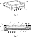
Fig.2 is an exterior schematic view of the reverse side for the construction of the receiver according to the first embodiment of the present application; -
Figure 3 is a cross-sectional view of the construction of a receiver according to the first embodiment of the present application; -
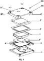
Figure 4 is an exploded view of the construction of a receiver according to a second embodiment of the present application; and -
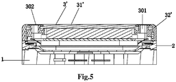
Figure 5 is a cross-sectional view of the construction of a receiver according to the second embodiment of the present application. - Wherein, the reference numerals comprise a
first housing 1, asecond housing 2, athird housing 3, a housing assembly 3', asound outlet hole 301, amesh fabric 302, a yoke 31', a plastic component 32', a yoke 4, amagnet 5, a magnet 5', awasher 6, a washer 6', avoice coil 7, avibration diaphragm 8, a vibration diaphragm 8', a reinforcingportion 9, a reinforcing portion 9', 10 a metal ring, 11 a hearing aid voice coil, 12 a colloid. - In the following description, the contents of the present application will be described in detail in combination with the accompanying drawings below.
- Referring to
Fig. 1 ,Fig. 2 and Fig. 3 together, a receiver of the present embodiment comprises an external housing, which in particular comprises afirst housing 1, asecond housing 2 and athird housing 3 adapted with each other from top to bottom to form a cavity for accommodating a magnetic circuit system and a vibration system. Furthermore, the magnetic circuit system comprises a yoke 4, amagnet 5 bonded and fixed to a surface of the yoke 4, and awasher 6 covering a surface of themagnet 5. Thethird housing 3 is a rectangular frame structure and is formed by injection-molded, and the yoke 4 is accommodated in a accommodating space of thethird housing 3, and the gap between the yoke 4 and thethird housing 3 is filled with acolloid 12 for better sealing. The vibration system comprises avibration diaphragm 8 and avoice coil 7 bonded and fixed with thevibration diaphragm 8. Ametal ring 10 is used to support thevibration diaphragm 8, and themetal ring 10 is fixed with thesecond housing 2. In addition, in order to enhance the acoustic performance of the receiver at high frequency, a middle portion of thediaphragm 8 is also coupled with a reinforcingportion 9, in implementation, the reinforcingportion 9 is generally a structure of a rigid composite layer. In addition, the receiver of the present embodiment further comprises ahearing aid coil 11. When the receiver is assembled with a terminal electronic device, thehearing aid coil 11 can cooperate with a hearing aid to have an effect of amplifying a sound signal, thus it facilitates those hearing impaired persons. - In this embodiment, the
vibration diaphragm 8 is fixed on thesecond housing 2, and divides the receiver into a front sound cavity and a rear sound cavity. In particular, it can be understood that a space defined by thediaphragm 8, thesecond housing 2 and thefirst housing 1 forms the front sound cavity, and a space defined by thediaphragm 8, thesecond housing 2 and thethird housing 3 forms the rear sound cavity, and thethird housing 3 is provided with sound outlet hole(s) 301 communicating with outside environment, as the sound outlet hole(s) of the rear sound cavity. Thethird housing 3 is coupled with mesh fabric(s) 302 at positions corresponding to the sound outlet hole(s) 301 by injection-molding, and the mesh fabric(s) 302 isolate the rear sound cavity from outside environment. - By means of the above-described technical solution, a mesh fabric is coupled on the sound outlet hole of the rear sound cavity to prevent impurities such as dust, fiber and fine particles in the outside environment from falling into the rear sound cavity, thereby improving the performance degradation of the product caused by the impurities, and further ensuring the acoustic performance of the product.
- Preferably, the sound outlet hole(s) 301 are provided at corners of the
third housing 3, and the mesh fabric(s) 302 are coupled by injection-molding in corresponding to the corners of thethird housing 3 and cover thesound outlet holes 301, furthermore, the mesh fabric(s) 302 can have a sector, a circular or a square structure and the like. In practice, in implementation, as long as the mesh fabric can cover thesound hole 301, the mesh fabric(s) can be any regular or irregular shape, and the specific shape thereof are not limited thereto. - Referring to
Fig. 4 andFig. 5 together, the main difference between the present embodiment and the first embodiment is that, in the first embodiment, the structure of the yoke as the magnetic circuit system and the third housing as the external housing are separate configurations, in this embodiment, the two configurations are integrally injection-molded to form a housing assembly 3'. That is to say, at this time, the housing assembly 3' specifically comprises a yoke 31' and a plastic component 32' positioned at a corner, and the third housing is the plastic component 32' described herein. - In the present embodiment, a vibration diaphragm 8' divides the receiver into a front sound cavity and a rear sound cavity, and sound outlet hole(s) 301 of the rear sound cavity are arranged on the plastic component 32' positioned at corners of the housing assembly 3', and the mesh fabric(s) 302 are integrally coupled by injection-molding at positions corresponding to the sound outlet hole(s) 301 so as to isolate the rear sound cavity from the outside environment. The specific shapes of the mesh fabric(s) 302 are the same as that of the first embodiment, and are not specifically limited thereto as long as the mesh fabric(s) can cover the sound hole(s) 301.
- In this embodiment, a magnet 5' in particular comprises a center magnet and two side magnets disposed opposed to each other along a pair of opposite sides of the center magnet. Correspondingly, a washer 6' comprises a center washer covering a surface of the center magnet and side washers covering the side magnets. Herein, the vibration diaphragm 8' of the vibration system is designed as a silicon membrane, which can improve the temperature resistance performance of the vibration diaphragm and increase the vibration amplitude of the vibration diaphragm. The method of fixing the vibration diaphragm is to combine with the
second housing 2 by injection-molding. In addition, a reinforcing portion 9' used for enhancing the high-frequency performance of the product has a concave structure, and can reduce the thickness of the product while optimizing the acoustic performance of the product. - It should be noted that the technical solution is intended to inject molding the mesh fabric in correspondence to the position of the sound outlet hole of the rear sound cavity so as to isolate the rear sound cavity from the outside environment, and the implementation thereof has no relation to the specific design of each component of the magnetic circuit system and the vibration system, that is to say, the implementation of the present technical solution is not limited to the above-described magnetic circuit structure, the structure of the vibration diaphragm or the reinforcing portion and the like, and as long as a mesh fabric is injection-molded at the position of the sound outlet hole of the rear sound cavity of the receiver product, it should be regarded as the protection scope of the present application.
- The above embodiments are merely embodiment examples of the present application, and are not intended to limit the protection scope of the present application. All the equivalent modifications or changes which can be performed by the skilled in the art according to the disclosure contents of the present application should be contained in the protection scope described in claims.
Claims (9)
- A receiver comprising an external housing, wherein the external housing comprises a first housing, a second housing and a third housing adapted with each other from top to bottom, a vibration system is accommodated in a cavity formed by the external housing and comprises a vibration diaphragm dividing the receiver into a front sound cavity and a rear sound cavity, wherein the third housing is injection-molded and provided with a sound outlet hole of the rear sound cavity which is in communication with outside environment, the third housing is coupled with a mesh fabric at a position corresponding to the sound outlet hole by injection-molding, and the mesh fabric isolates the rear sound cavity from the outside environment.
- The receiver according to claim 1, wherein the sound outlet hole is provided at a corner of the third housing, and the mesh fabric is coupled by injection-molding at a position corresponding to the corner of the third housing and covers the sound outlet hole.
- The receiver according to claim 2, wherein the mesh fabric has a sector, a circular or a square structure.
- The receiver according to claim 1, wherein a space defined by the vibration diaphragm, the second housing and the first housing forms the front sound cavity, and a space defined by the vibration diaphragm, the second housing and the third housing forms the rear sound cavity.
- The receiver according to claim 1, further comprising a magnetic circuit system which comprises a yoke, a magnet and a washer fixed within the yoke.
- The receiver according to claim 5, wherein the yoke and the third housing of the receiver are separate configurations, and a gap between the yoke and the third housing of the receiver is coated with colloid for sealing.
- The receiver according to claim 5, wherein the yoke is integrally injection-molded with the third housing of the receiver to form a housing assembly, and the third housing of the receiver is a plastic component positioned at a corner of the housing assembly.
- The receiver according to claim 7, wherein the plastic component is provided with a sound outlet hole of the rear sound cavity of the receiver.
- The receiver according to claim 1, wherein the vibration system further comprises a voice coil bonded and fixed with the vibration diaphragm, and a reinforcing portion is coupled to a center of the vibration diaphragm.
Applications Claiming Priority (2)
| Application Number | Priority Date | Filing Date | Title |
|---|---|---|---|
| CN201520712594 | 2015-09-15 | ||
| PCT/CN2016/089371 WO2017045463A1 (en) | 2015-09-15 | 2016-07-08 | Receiver |
Publications (4)
| Publication Number | Publication Date |
|---|---|
| EP3352472A1 true EP3352472A1 (en) | 2018-07-25 |
| EP3352472A4 EP3352472A4 (en) | 2019-01-30 |
| EP3352472B1 EP3352472B1 (en) | 2021-06-09 |
| EP3352472B8 EP3352472B8 (en) | 2021-09-15 |
Family
ID=58101928
Family Applications (2)
| Application Number | Title | Priority Date | Filing Date |
|---|---|---|---|
| EP15903948.6A Active EP3352476B1 (en) | 2015-09-15 | 2015-11-16 | Receiver |
| EP16845577.2A Active EP3352472B8 (en) | 2015-09-15 | 2016-07-08 | Receiver |
Family Applications Before (1)
| Application Number | Title | Priority Date | Filing Date |
|---|---|---|---|
| EP15903948.6A Active EP3352476B1 (en) | 2015-09-15 | 2015-11-16 | Receiver |
Country Status (4)
| Country | Link |
|---|---|
| US (1) | US10284936B2 (en) |
| EP (2) | EP3352476B1 (en) |
| CN (1) | CN205992985U (en) |
| WO (2) | WO2017045261A1 (en) |
Cited By (1)
| Publication number | Priority date | Publication date | Assignee | Title |
|---|---|---|---|---|
| US20220159384A1 (en) * | 2019-07-30 | 2022-05-19 | Goertek Inc. | Sounding device |
Families Citing this family (20)
| Publication number | Priority date | Publication date | Assignee | Title |
|---|---|---|---|---|
| CN107613438A (en) * | 2017-10-19 | 2018-01-19 | 江苏裕成电子有限公司 | Yin Qiang mechanisms |
| CN207638869U (en) * | 2017-11-30 | 2018-07-20 | 歌尔科技有限公司 | A kind of electronic equipment |
| CN108337614B (en) * | 2018-02-24 | 2020-05-19 | 歌尔股份有限公司 | Electroacoustic transducer |
| CN108551635B (en) * | 2018-05-28 | 2020-08-25 | 歌尔股份有限公司 | Micro speaker module |
| CN108632419B (en) * | 2018-07-11 | 2019-11-22 | 维沃移动通信有限公司 | a mobile terminal |
| CN109218938B (en) * | 2018-08-13 | 2023-11-14 | 歌尔股份有限公司 | terminal device |
| CN109246560B (en) * | 2018-08-13 | 2020-05-22 | 歌尔股份有限公司 | Sound producing device |
| CN109275074B (en) * | 2018-09-30 | 2020-12-22 | 瑞声科技(新加坡)有限公司 | Sound production device |
| CN109587607B (en) * | 2018-12-26 | 2023-11-24 | 常州元太科技有限公司 | Planar spring plate with linear vibration function for super linear speakers |
| WO2020227956A1 (en) * | 2019-05-10 | 2020-11-19 | 瑞声声学科技(深圳)有限公司 | Magnetic circuit system and a loudspeaker using same |
| US12121580B2 (en) | 2019-06-14 | 2024-10-22 | Board Of Regents, The University Of Texas System | Antibacterial photodynamic therapy using copper-cysteamine nanoparticles |
| CN110351638A (en) * | 2019-06-26 | 2019-10-18 | 瑞声科技(新加坡)有限公司 | A kind of loudspeaker |
| CN110381426B (en) * | 2019-07-11 | 2021-08-31 | 瑞声光电科技(常州)有限公司 | Loudspeaker box |
| US11316283B2 (en) * | 2019-07-24 | 2022-04-26 | Delta Electronics, Inc. | Dual polarized antenna |
| CN210781299U (en) * | 2019-11-01 | 2020-06-16 | 瑞声科技(新加坡)有限公司 | Loudspeaker box |
| US12109753B2 (en) * | 2020-03-11 | 2024-10-08 | Meta Platforms Technologies, Llc | Method of covering a housing with a textile and related systems and devices |
| CN111405097B (en) * | 2020-03-18 | 2022-01-14 | Oppo广东移动通信有限公司 | Electronic equipment |
| EP4124070B1 (en) | 2020-08-12 | 2026-01-28 | Shenzhen Shokz Co., Ltd. | Acoustic device and production method for protective component thereof |
| CN112312246B (en) * | 2020-11-30 | 2022-03-01 | 瑞声新能源发展(常州)有限公司科教城分公司 | Sound production device |
| CN214101762U (en) * | 2020-12-16 | 2021-08-31 | 瑞声光电科技(常州)有限公司 | speaker |
Family Cites Families (17)
| Publication number | Priority date | Publication date | Assignee | Title |
|---|---|---|---|---|
| JP3454720B2 (en) * | 1998-07-30 | 2003-10-06 | 三洋電機株式会社 | Earpiece |
| EP1072167B1 (en) * | 1999-01-26 | 2003-10-29 | Koninklijke Philips Electronics N.V. | Apparatus having a housing which accommodates a sound transducer and which has a passage |
| AT411558B (en) * | 1999-11-05 | 2004-02-25 | Akg Acoustics Gmbh | ELECTROACOUSTIC CONVERTER |
| JP2005006205A (en) * | 2003-06-13 | 2005-01-06 | Fujitsu Ltd | Mobile terminal |
| CN2632952Y (en) * | 2003-07-09 | 2004-08-11 | 曾斌 | Vibration telephone receiver |
| US7386138B2 (en) * | 2004-02-16 | 2008-06-10 | Citizen Electronics Co., Ltd. | Multifunction speaker |
| EP1686834A1 (en) * | 2005-01-28 | 2006-08-02 | Sonion Horsens A/S | Miniature multi-loudspeaker module |
| WO2010004815A1 (en) * | 2008-07-10 | 2010-01-14 | 株式会社オーディオテクニカ | Headphone unit and headphones |
| US20120328145A1 (en) | 2010-12-20 | 2012-12-27 | Hon Hai Precision Industry Co., Ltd. | Wired earphone with coiled adhesive tape |
| US10225633B2 (en) | 2011-07-01 | 2019-03-05 | Nokia Technologies Oy | Dust shielding apparatus |
| CN102572657B (en) * | 2011-12-30 | 2016-02-17 | 歌尔声学股份有限公司 | Mini-type moving-ring acoustic generator |
| WO2014103278A1 (en) * | 2012-12-28 | 2014-07-03 | パナソニック株式会社 | Loudspeaker, electronic apparatus using same, and mobile apparatus |
| CN103581809B (en) * | 2013-11-13 | 2017-09-12 | 惠州Tcl移动通信有限公司 | A kind of terminal and its receiver |
| CN104053102B (en) | 2014-06-30 | 2018-03-02 | 歌尔股份有限公司 | Loudspeaker module |
| CN203984670U (en) * | 2014-07-24 | 2014-12-03 | 歌尔声学股份有限公司 | Microspeaker |
| CN104244130B (en) | 2014-09-05 | 2018-05-22 | 歌尔股份有限公司 | A kind of earphone |
| CN104883648B (en) * | 2015-05-13 | 2019-05-17 | 歌尔股份有限公司 | Vibrating speaker |
-
2015
- 2015-11-16 WO PCT/CN2015/094684 patent/WO2017045261A1/en not_active Ceased
- 2015-11-16 EP EP15903948.6A patent/EP3352476B1/en active Active
-
2016
- 2016-07-08 EP EP16845577.2A patent/EP3352472B8/en active Active
- 2016-07-08 US US15/745,101 patent/US10284936B2/en active Active
- 2016-07-08 WO PCT/CN2016/089371 patent/WO2017045463A1/en not_active Ceased
- 2016-07-11 CN CN201620727105.1U patent/CN205992985U/en not_active Expired - Fee Related
Cited By (2)
| Publication number | Priority date | Publication date | Assignee | Title |
|---|---|---|---|---|
| US20220159384A1 (en) * | 2019-07-30 | 2022-05-19 | Goertek Inc. | Sounding device |
| US12058505B2 (en) * | 2019-07-30 | 2024-08-06 | Goertek Inc. | Sounding device |
Also Published As
| Publication number | Publication date |
|---|---|
| EP3352476B1 (en) | 2020-09-16 |
| EP3352472A4 (en) | 2019-01-30 |
| US20180270555A1 (en) | 2018-09-20 |
| CN205992985U (en) | 2017-03-01 |
| EP3352472B1 (en) | 2021-06-09 |
| EP3352476A1 (en) | 2018-07-25 |
| EP3352472B8 (en) | 2021-09-15 |
| WO2017045261A1 (en) | 2017-03-23 |
| US10284936B2 (en) | 2019-05-07 |
| WO2017045463A1 (en) | 2017-03-23 |
| EP3352476A4 (en) | 2019-01-23 |
Similar Documents
| Publication | Publication Date | Title |
|---|---|---|
| US10284936B2 (en) | Receiver | |
| KR101691362B1 (en) | Ultrathin loudspeaker module | |
| US10567858B2 (en) | Loudspeaker module and terminal device | |
| US10356530B2 (en) | Electronic device and loudspeaker thereof | |
| US10820106B2 (en) | Speaker module | |
| CN209731559U (en) | A kind of loudspeaker mould group | |
| KR20090013908A (en) | Speaker mounting structure of portable terminal | |
| US20200213753A1 (en) | Loudspeaker | |
| CN205596313U (en) | Sound electric power switching device and audio equipment thereof | |
| CN205142510U (en) | speaker | |
| CN203851284U (en) | Loudspeaker module group and electronic device comprising same | |
| WO2016078561A1 (en) | Loudspeaker structure | |
| CN104883648B (en) | Vibrating speaker | |
| KR20140116947A (en) | Sounder module and assembly method thereof | |
| CN207460510U (en) | A kind of loud speaker module | |
| EP3829193B1 (en) | Sound emitting structure and terminal | |
| US10129619B2 (en) | Receiver | |
| CN105848073A (en) | Receiver having diaphragm with improved rigidity | |
| US10104476B2 (en) | Miniature loudspeaker | |
| CN202818587U (en) | Micro loudspeaker | |
| KR200454024Y1 (en) | Multifunction micro speaker | |
| CN208638695U (en) | Loudspeaker mould group | |
| CN207166759U (en) | Single magnetic speaker and electronic equipment | |
| CN202514066U (en) | Multifunctional mini-size loudspeaker | |
| KR20060009112A (en) | Round speaker |
Legal Events
| Date | Code | Title | Description |
|---|---|---|---|
| STAA | Information on the status of an ep patent application or granted ep patent |
Free format text: STATUS: THE INTERNATIONAL PUBLICATION HAS BEEN MADE |
|
| PUAI | Public reference made under article 153(3) epc to a published international application that has entered the european phase |
Free format text: ORIGINAL CODE: 0009012 |
|
| STAA | Information on the status of an ep patent application or granted ep patent |
Free format text: STATUS: REQUEST FOR EXAMINATION WAS MADE |
|
| 17P | Request for examination filed |
Effective date: 20180223 |
|
| AK | Designated contracting states |
Kind code of ref document: A1 Designated state(s): AL AT BE BG CH CY CZ DE DK EE ES FI FR GB GR HR HU IE IS IT LI LT LU LV MC MK MT NL NO PL PT RO RS SE SI SK SM TR |
|
| AX | Request for extension of the european patent |
Extension state: BA ME |
|
| DAV | Request for validation of the european patent (deleted) | ||
| DAX | Request for extension of the european patent (deleted) | ||
| REG | Reference to a national code |
Ref country code: DE Ref legal event code: R079 Ref document number: 602016059212 Country of ref document: DE Free format text: PREVIOUS MAIN CLASS: H04R0001100000 Ipc: H04R0009020000 |
|
| A4 | Supplementary search report drawn up and despatched |
Effective date: 20190107 |
|
| RIC1 | Information provided on ipc code assigned before grant |
Ipc: H04R 9/08 20060101ALI20181221BHEP Ipc: H04R 9/02 20060101AFI20181221BHEP Ipc: H04R 1/06 20060101ALI20181221BHEP |
|
| GRAP | Despatch of communication of intention to grant a patent |
Free format text: ORIGINAL CODE: EPIDOSNIGR1 |
|
| STAA | Information on the status of an ep patent application or granted ep patent |
Free format text: STATUS: GRANT OF PATENT IS INTENDED |
|
| INTG | Intention to grant announced |
Effective date: 20210113 |
|
| GRAS | Grant fee paid |
Free format text: ORIGINAL CODE: EPIDOSNIGR3 |
|
| GRAA | (expected) grant |
Free format text: ORIGINAL CODE: 0009210 |
|
| STAA | Information on the status of an ep patent application or granted ep patent |
Free format text: STATUS: THE PATENT HAS BEEN GRANTED |
|
| AK | Designated contracting states |
Kind code of ref document: B1 Designated state(s): AL AT BE BG CH CY CZ DE DK EE ES FI FR GB GR HR HU IE IS IT LI LT LU LV MC MK MT NL NO PL PT RO RS SE SI SK SM TR |
|
| REG | Reference to a national code |
Ref country code: GB Ref legal event code: FG4D |
|
| REG | Reference to a national code |
Ref country code: CH Ref legal event code: EP Ref country code: AT Ref legal event code: REF Ref document number: 1401452 Country of ref document: AT Kind code of ref document: T Effective date: 20210615 |
|
| REG | Reference to a national code |
Ref country code: DE Ref legal event code: R096 Ref document number: 602016059212 Country of ref document: DE |
|
| REG | Reference to a national code |
Ref country code: IE Ref legal event code: FG4D |
|
| GRAT | Correction requested after decision to grant or after decision to maintain patent in amended form |
Free format text: ORIGINAL CODE: EPIDOSNCDEC |
|
| REG | Reference to a national code |
Ref country code: CH Ref legal event code: PK Free format text: BERICHTIGUNG B8 |
|
| RAP4 | Party data changed (patent owner data changed or rights of a patent transferred) |
Owner name: GOERTEK INC. |
|
| REG | Reference to a national code |
Ref country code: LT Ref legal event code: MG9D |
|
| PG25 | Lapsed in a contracting state [announced via postgrant information from national office to epo] |
Ref country code: LT Free format text: LAPSE BECAUSE OF FAILURE TO SUBMIT A TRANSLATION OF THE DESCRIPTION OR TO PAY THE FEE WITHIN THE PRESCRIBED TIME-LIMIT Effective date: 20210609 Ref country code: FI Free format text: LAPSE BECAUSE OF FAILURE TO SUBMIT A TRANSLATION OF THE DESCRIPTION OR TO PAY THE FEE WITHIN THE PRESCRIBED TIME-LIMIT Effective date: 20210609 Ref country code: BG Free format text: LAPSE BECAUSE OF FAILURE TO SUBMIT A TRANSLATION OF THE DESCRIPTION OR TO PAY THE FEE WITHIN THE PRESCRIBED TIME-LIMIT Effective date: 20210909 Ref country code: HR Free format text: LAPSE BECAUSE OF FAILURE TO SUBMIT A TRANSLATION OF THE DESCRIPTION OR TO PAY THE FEE WITHIN THE PRESCRIBED TIME-LIMIT Effective date: 20210609 |
|
| REG | Reference to a national code |
Ref country code: AT Ref legal event code: MK05 Ref document number: 1401452 Country of ref document: AT Kind code of ref document: T Effective date: 20210609 |
|
| REG | Reference to a national code |
Ref country code: NL Ref legal event code: MP Effective date: 20210609 |
|
| PG25 | Lapsed in a contracting state [announced via postgrant information from national office to epo] |
Ref country code: GR Free format text: LAPSE BECAUSE OF FAILURE TO SUBMIT A TRANSLATION OF THE DESCRIPTION OR TO PAY THE FEE WITHIN THE PRESCRIBED TIME-LIMIT Effective date: 20210910 Ref country code: LV Free format text: LAPSE BECAUSE OF FAILURE TO SUBMIT A TRANSLATION OF THE DESCRIPTION OR TO PAY THE FEE WITHIN THE PRESCRIBED TIME-LIMIT Effective date: 20210609 Ref country code: SE Free format text: LAPSE BECAUSE OF FAILURE TO SUBMIT A TRANSLATION OF THE DESCRIPTION OR TO PAY THE FEE WITHIN THE PRESCRIBED TIME-LIMIT Effective date: 20210609 Ref country code: RS Free format text: LAPSE BECAUSE OF FAILURE TO SUBMIT A TRANSLATION OF THE DESCRIPTION OR TO PAY THE FEE WITHIN THE PRESCRIBED TIME-LIMIT Effective date: 20210609 Ref country code: NO Free format text: LAPSE BECAUSE OF FAILURE TO SUBMIT A TRANSLATION OF THE DESCRIPTION OR TO PAY THE FEE WITHIN THE PRESCRIBED TIME-LIMIT Effective date: 20210909 |
|
| PG25 | Lapsed in a contracting state [announced via postgrant information from national office to epo] |
Ref country code: ES Free format text: LAPSE BECAUSE OF FAILURE TO SUBMIT A TRANSLATION OF THE DESCRIPTION OR TO PAY THE FEE WITHIN THE PRESCRIBED TIME-LIMIT Effective date: 20210609 Ref country code: PT Free format text: LAPSE BECAUSE OF FAILURE TO SUBMIT A TRANSLATION OF THE DESCRIPTION OR TO PAY THE FEE WITHIN THE PRESCRIBED TIME-LIMIT Effective date: 20211011 Ref country code: RO Free format text: LAPSE BECAUSE OF FAILURE TO SUBMIT A TRANSLATION OF THE DESCRIPTION OR TO PAY THE FEE WITHIN THE PRESCRIBED TIME-LIMIT Effective date: 20210609 Ref country code: NL Free format text: LAPSE BECAUSE OF FAILURE TO SUBMIT A TRANSLATION OF THE DESCRIPTION OR TO PAY THE FEE WITHIN THE PRESCRIBED TIME-LIMIT Effective date: 20210609 Ref country code: AT Free format text: LAPSE BECAUSE OF FAILURE TO SUBMIT A TRANSLATION OF THE DESCRIPTION OR TO PAY THE FEE WITHIN THE PRESCRIBED TIME-LIMIT Effective date: 20210609 Ref country code: CZ Free format text: LAPSE BECAUSE OF FAILURE TO SUBMIT A TRANSLATION OF THE DESCRIPTION OR TO PAY THE FEE WITHIN THE PRESCRIBED TIME-LIMIT Effective date: 20210609 Ref country code: EE Free format text: LAPSE BECAUSE OF FAILURE TO SUBMIT A TRANSLATION OF THE DESCRIPTION OR TO PAY THE FEE WITHIN THE PRESCRIBED TIME-LIMIT Effective date: 20210609 Ref country code: SK Free format text: LAPSE BECAUSE OF FAILURE TO SUBMIT A TRANSLATION OF THE DESCRIPTION OR TO PAY THE FEE WITHIN THE PRESCRIBED TIME-LIMIT Effective date: 20210609 Ref country code: SM Free format text: LAPSE BECAUSE OF FAILURE TO SUBMIT A TRANSLATION OF THE DESCRIPTION OR TO PAY THE FEE WITHIN THE PRESCRIBED TIME-LIMIT Effective date: 20210609 |
|
| PG25 | Lapsed in a contracting state [announced via postgrant information from national office to epo] |
Ref country code: PL Free format text: LAPSE BECAUSE OF FAILURE TO SUBMIT A TRANSLATION OF THE DESCRIPTION OR TO PAY THE FEE WITHIN THE PRESCRIBED TIME-LIMIT Effective date: 20210609 |
|
| REG | Reference to a national code |
Ref country code: CH Ref legal event code: PL |
|
| REG | Reference to a national code |
Ref country code: DE Ref legal event code: R097 Ref document number: 602016059212 Country of ref document: DE |
|
| PG25 | Lapsed in a contracting state [announced via postgrant information from national office to epo] |
Ref country code: MC Free format text: LAPSE BECAUSE OF FAILURE TO SUBMIT A TRANSLATION OF THE DESCRIPTION OR TO PAY THE FEE WITHIN THE PRESCRIBED TIME-LIMIT Effective date: 20210609 |
|
| REG | Reference to a national code |
Ref country code: BE Ref legal event code: MM Effective date: 20210731 |
|
| PLBE | No opposition filed within time limit |
Free format text: ORIGINAL CODE: 0009261 |
|
| STAA | Information on the status of an ep patent application or granted ep patent |
Free format text: STATUS: NO OPPOSITION FILED WITHIN TIME LIMIT |
|
| PG25 | Lapsed in a contracting state [announced via postgrant information from national office to epo] |
Ref country code: LI Free format text: LAPSE BECAUSE OF NON-PAYMENT OF DUE FEES Effective date: 20210731 Ref country code: DK Free format text: LAPSE BECAUSE OF FAILURE TO SUBMIT A TRANSLATION OF THE DESCRIPTION OR TO PAY THE FEE WITHIN THE PRESCRIBED TIME-LIMIT Effective date: 20210609 Ref country code: CH Free format text: LAPSE BECAUSE OF NON-PAYMENT OF DUE FEES Effective date: 20210731 |
|
| 26N | No opposition filed |
Effective date: 20220310 |
|
| PG25 | Lapsed in a contracting state [announced via postgrant information from national office to epo] |
Ref country code: LU Free format text: LAPSE BECAUSE OF NON-PAYMENT OF DUE FEES Effective date: 20210708 Ref country code: AL Free format text: LAPSE BECAUSE OF FAILURE TO SUBMIT A TRANSLATION OF THE DESCRIPTION OR TO PAY THE FEE WITHIN THE PRESCRIBED TIME-LIMIT Effective date: 20210609 |
|
| PG25 | Lapsed in a contracting state [announced via postgrant information from national office to epo] |
Ref country code: IT Free format text: LAPSE BECAUSE OF FAILURE TO SUBMIT A TRANSLATION OF THE DESCRIPTION OR TO PAY THE FEE WITHIN THE PRESCRIBED TIME-LIMIT Effective date: 20210609 Ref country code: IE Free format text: LAPSE BECAUSE OF NON-PAYMENT OF DUE FEES Effective date: 20210708 Ref country code: BE Free format text: LAPSE BECAUSE OF NON-PAYMENT OF DUE FEES Effective date: 20210731 |
|
| PG25 | Lapsed in a contracting state [announced via postgrant information from national office to epo] |
Ref country code: HU Free format text: LAPSE BECAUSE OF FAILURE TO SUBMIT A TRANSLATION OF THE DESCRIPTION OR TO PAY THE FEE WITHIN THE PRESCRIBED TIME-LIMIT; INVALID AB INITIO Effective date: 20160708 |
|
| PG25 | Lapsed in a contracting state [announced via postgrant information from national office to epo] |
Ref country code: CY Free format text: LAPSE BECAUSE OF FAILURE TO SUBMIT A TRANSLATION OF THE DESCRIPTION OR TO PAY THE FEE WITHIN THE PRESCRIBED TIME-LIMIT Effective date: 20210609 |
|
| PG25 | Lapsed in a contracting state [announced via postgrant information from national office to epo] |
Ref country code: MK Free format text: LAPSE BECAUSE OF FAILURE TO SUBMIT A TRANSLATION OF THE DESCRIPTION OR TO PAY THE FEE WITHIN THE PRESCRIBED TIME-LIMIT Effective date: 20210609 |
|
| PG25 | Lapsed in a contracting state [announced via postgrant information from national office to epo] |
Ref country code: TR Free format text: LAPSE BECAUSE OF FAILURE TO SUBMIT A TRANSLATION OF THE DESCRIPTION OR TO PAY THE FEE WITHIN THE PRESCRIBED TIME-LIMIT Effective date: 20210609 |
|
| PG25 | Lapsed in a contracting state [announced via postgrant information from national office to epo] |
Ref country code: MT Free format text: LAPSE BECAUSE OF FAILURE TO SUBMIT A TRANSLATION OF THE DESCRIPTION OR TO PAY THE FEE WITHIN THE PRESCRIBED TIME-LIMIT Effective date: 20210609 |
|
| PGFP | Annual fee paid to national office [announced via postgrant information from national office to epo] |
Ref country code: DE Payment date: 20250711 Year of fee payment: 10 |
|
| PGFP | Annual fee paid to national office [announced via postgrant information from national office to epo] |
Ref country code: GB Payment date: 20250723 Year of fee payment: 10 |
|
| PGFP | Annual fee paid to national office [announced via postgrant information from national office to epo] |
Ref country code: FR Payment date: 20250730 Year of fee payment: 10 |