EP3352453A1 - Photographing method for intelligent flight device and intelligent flight device - Google Patents
Photographing method for intelligent flight device and intelligent flight device Download PDFInfo
- Publication number
- EP3352453A1 EP3352453A1 EP18152536.1A EP18152536A EP3352453A1 EP 3352453 A1 EP3352453 A1 EP 3352453A1 EP 18152536 A EP18152536 A EP 18152536A EP 3352453 A1 EP3352453 A1 EP 3352453A1
- Authority
- EP
- European Patent Office
- Prior art keywords
- projection
- light source
- angle
- flight device
- photographing
- Prior art date
- Legal status (The legal status is an assumption and is not a legal conclusion. Google has not performed a legal analysis and makes no representation as to the accuracy of the status listed.)
- Granted
Links
Images


Classifications
-
- G—PHYSICS
- G01—MEASURING; TESTING
- G01C—MEASURING DISTANCES, LEVELS OR BEARINGS; SURVEYING; NAVIGATION; GYROSCOPIC INSTRUMENTS; PHOTOGRAMMETRY OR VIDEOGRAMMETRY
- G01C1/00—Measuring angles
-
- H—ELECTRICITY
- H04—ELECTRIC COMMUNICATION TECHNIQUE
- H04N—PICTORIAL COMMUNICATION, e.g. TELEVISION
- H04N23/00—Cameras or camera modules comprising electronic image sensors; Control thereof
- H04N23/60—Control of cameras or camera modules
- H04N23/64—Computer-aided capture of images, e.g. transfer from script file into camera, check of taken image quality, advice or proposal for image composition or decision on when to take image
-
- H—ELECTRICITY
- H04—ELECTRIC COMMUNICATION TECHNIQUE
- H04N—PICTORIAL COMMUNICATION, e.g. TELEVISION
- H04N23/00—Cameras or camera modules comprising electronic image sensors; Control thereof
- H04N23/60—Control of cameras or camera modules
- H04N23/66—Remote control of cameras or camera parts, e.g. by remote control devices
- H04N23/661—Transmitting camera control signals through networks, e.g. control via the Internet
-
- G—PHYSICS
- G03—PHOTOGRAPHY; CINEMATOGRAPHY; ANALOGOUS TECHNIQUES USING WAVES OTHER THAN OPTICAL WAVES; ELECTROGRAPHY; HOLOGRAPHY
- G03B—APPARATUS OR ARRANGEMENTS FOR TAKING PHOTOGRAPHS OR FOR PROJECTING OR VIEWING THEM; APPARATUS OR ARRANGEMENTS EMPLOYING ANALOGOUS TECHNIQUES USING WAVES OTHER THAN OPTICAL WAVES; ACCESSORIES THEREFOR
- G03B15/00—Special procedures for taking photographs; Apparatus therefor
- G03B15/006—Apparatus mounted on flying objects
-
- G—PHYSICS
- G03—PHOTOGRAPHY; CINEMATOGRAPHY; ANALOGOUS TECHNIQUES USING WAVES OTHER THAN OPTICAL WAVES; ELECTROGRAPHY; HOLOGRAPHY
- G03B—APPARATUS OR ARRANGEMENTS FOR TAKING PHOTOGRAPHS OR FOR PROJECTING OR VIEWING THEM; APPARATUS OR ARRANGEMENTS EMPLOYING ANALOGOUS TECHNIQUES USING WAVES OTHER THAN OPTICAL WAVES; ACCESSORIES THEREFOR
- G03B7/00—Control of exposure by setting shutters, diaphragms or filters, separately or conjointly
- G03B7/08—Control effected solely on the basis of the response, to the intensity of the light received by the camera, of a built-in light-sensitive device
-
- G—PHYSICS
- G05—CONTROLLING; REGULATING
- G05D—SYSTEMS FOR CONTROLLING OR REGULATING NON-ELECTRIC VARIABLES
- G05D1/00—Control of position, course, altitude or attitude of land, water, air or space vehicles, e.g. using automatic pilots
- G05D1/08—Control of attitude, i.e. control of roll, pitch, or yaw
- G05D1/0808—Control of attitude, i.e. control of roll, pitch, or yaw specially adapted for aircraft
-
- H—ELECTRICITY
- H04—ELECTRIC COMMUNICATION TECHNIQUE
- H04N—PICTORIAL COMMUNICATION, e.g. TELEVISION
- H04N23/00—Cameras or camera modules comprising electronic image sensors; Control thereof
- H04N23/60—Control of cameras or camera modules
- H04N23/66—Remote control of cameras or camera parts, e.g. by remote control devices
-
- H—ELECTRICITY
- H04—ELECTRIC COMMUNICATION TECHNIQUE
- H04N—PICTORIAL COMMUNICATION, e.g. TELEVISION
- H04N23/00—Cameras or camera modules comprising electronic image sensors; Control thereof
- H04N23/60—Control of cameras or camera modules
- H04N23/695—Control of camera direction for changing a field of view, e.g. pan, tilt or based on tracking of objects
-
- H—ELECTRICITY
- H04—ELECTRIC COMMUNICATION TECHNIQUE
- H04N—PICTORIAL COMMUNICATION, e.g. TELEVISION
- H04N23/00—Cameras or camera modules comprising electronic image sensors; Control thereof
- H04N23/70—Circuitry for compensating brightness variation in the scene
- H04N23/73—Circuitry for compensating brightness variation in the scene by influencing the exposure time
-
- H—ELECTRICITY
- H04—ELECTRIC COMMUNICATION TECHNIQUE
- H04N—PICTORIAL COMMUNICATION, e.g. TELEVISION
- H04N23/00—Cameras or camera modules comprising electronic image sensors; Control thereof
- H04N23/80—Camera processing pipelines; Components thereof
-
- B—PERFORMING OPERATIONS; TRANSPORTING
- B64—AIRCRAFT; AVIATION; COSMONAUTICS
- B64U—UNMANNED AERIAL VEHICLES [UAV]; EQUIPMENT THEREFOR
- B64U2101/00—UAVs specially adapted for particular uses or applications
- B64U2101/30—UAVs specially adapted for particular uses or applications for imaging, photography or videography
-
- B—PERFORMING OPERATIONS; TRANSPORTING
- B64—AIRCRAFT; AVIATION; COSMONAUTICS
- B64U—UNMANNED AERIAL VEHICLES [UAV]; EQUIPMENT THEREFOR
- B64U2201/00—UAVs characterised by their flight controls
- B64U2201/10—UAVs characterised by their flight controls autonomous, i.e. by navigating independently from ground or air stations, e.g. by using inertial navigation systems [INS]
Definitions
- the present disclosure relates to the technologies of electronic devices, and more particularly, to a photographing method for an intelligent flight device and the intelligent flight device.
- the light rays emitted from the light source will travel by the intelligent flight device to generate a projection.
- a projection of the unmanned camera may be generated on the ground, and under such situation the generated projection is inclined to be incorporated into the photographed pictures or videos.
- the present disclosure provides a photographing method for an intelligent flight device and an intelligent flight device.
- a photographing method for an intelligent flight device includes:
- the determining the light source angle includes any one of:
- the determining the bearing of the projection on the horizontal plane which is generated by travel of the light emitted from the target light source passing the intelligent flight device according to the light source angle includes:
- performing photographing based on the current photographing angle of the intelligent flight device and the bearing of the projection includes:
- determining whether the bearing of the projection is within the photographing range based on the current photographing angle and the bearing of the projection includes:
- an intelligent flight device including:
- the first determination module includes:
- the second determination module includes:
- the photographing module includes:
- the photographing module further includes:
- an intelligent flight device including:
- a computer program which when executing on a processor, performs any one of the above methods.
- embodiments of the present disclosure provide a photographing method for an intelligent flight device which is capable of avoiding incorporation of the projection into the photographed pictures or videos and thus improving the quality of photographing.
- the photographing method for an intelligent provided by embodiments of the present disclosure may be executed by the intelligent flight device which may be an unmanned camera and the like.
- Fig. 1 is a flow chart of a photographing method for an intelligent flight device according to an exemplary embodiment. As shown in Fig. 1 , the photographing for an intelligent flight device may include the following steps.
- a light source angle is determined.
- the light source angle is an angle between a current beam direction of a target light source and a vertical direction
- the target light source is a light source capable of generating a projection of the intelligent flight device
- the vertical direction is a direction perpendicular to a horizontal plane.
- step 102 according to the light source angle, a bearing of a projection on the horizontal plane which is generated by travel of the light emitted from the target light source passing the intelligent flight device is determined.
- step 103 photographing is performed based on a current photographing angle of the intelligent flight device and the bearing of the projection.
- an angle between a current beam direction of a target light source which is a light source capable of generating a projection of an intelligent flight device and a vertical direction is determined; according to the determined angle, a bearing of a projection on the horizontal plane which is generated by travel of the light emitted from the target light source passing the intelligent flight device can be determined. Since the bearing of the projection is determined, photographing can be performed based on a current photographing angle of the intelligent flight device and the bearing of the projection. Thus, the technical solutions in the embodiment can avoid incorporation of the projection into the photographed pictures or videos, thereby improving the quality of photographing.
- the determining the light source angle includes any one of:
- the determining the bearing of the projection on the horizontal plane which is generated by travel of the light emitted from the target light source passing the intelligent flight device according to the light source angle includes:
- performing photographing based on the current photographing angle of the intelligent flight device and the bearing of the projection includes:
- determining whether the bearing of the projection is within the photographing range based on the current photographing angle and the bearing of the projection includes:
- Fig. 2A is a flow chart of a photographing method for an intelligent flight device according to another exemplary embodiment. As shown in Fig. 2A , the photographing method for an intelligent flight device may be applied in an intelligent control device. The photographing method for an intelligent flight device may include the following steps.
- a light source angle is determined.
- the light source angle is an angle between a current beam direction of a target light source and a vertical direction
- the target light source is a light source capable of generating a projection of the intelligent flight device
- the vertical direction is a direction perpendicular to a horizontal plane.
- the target light source may include the sun, or a lighting device and the like, and embodiments of the present disclosure do not impose specific limitations on this.
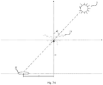
- the target light source in Fig. 2B is the sun 21, and the angle between the current bearing of the target light source 21 and the vertical direction is ⁇ , i.e., the light source angle is ⁇ .
- the determination of the light source angle may be realized by use of any one of the following approaches:
- a plurality of light intensities are determined by use of a configured light sensor and a first preset angle corresponding to a maximum light intensity is determined as the light source angle.
- the plurality of first preset angles correspond to the plurality of light intensities one to one.
- the intelligent flight device may be provided with a light sensor. It is easy to understand that only when the height of the target light source from the horizontal plane is higher than the height of the intelligent flight device from the horizontal plane, the target light source may generate a projection of the intelligent flight device.
- the light sensor may be provided at the top of the intelligent flight device and can be rotated so as to collect the light emitted from the light source based on the plurality of first preset angles.
- Each of the plurality of first preset angles may be set by users according to actual needs, or may be set by the intelligent flight device by default, and embodiments of the present do not impose limitations on this.
- the plurality of first preset angles may be preset angles of 30 degrees, 60 degrees, 90 degrees, -30 degrees and -60 degrees with respect to the vertical direction.
- the intelligent flight device may collect light rays every 30 degrees by use of the light sensor to obtain the plurality of light intensities corresponding to the plurality of first preset angles.
- the intelligent flight device determines from the plurality of light intensities a maximum light intensity, and determines a first preset angle corresponding to the maximum light intensity as the light source angle.
- a plurality of exposures are determined, and a second preset angle corresponding to a maximum exposure is determined as the light source angle.
- the plurality of second preset angles correspond to the plurality of exposures one to one.
- the intelligent flight device may collect light rays based on a plurality of second preset angles by means of a camera device of the intelligent flight device to determine a plurality of exposures.
- the second preset angle corresponding to the maximum exposure is determined as the light source angle.
- Each of the plurality of first preset angles may be set by users according to actual needs, or may be set by the intelligent flight device by default, and embodiments of the present do not impose limitations on this.
- the intelligent flight device determines position information regarding the current position of the intelligent flight device using a positioning function and obtains a system time point; based on the position information and the system time point, the intelligent flight device obtains from a designated server a sun rising angle corresponding to the position information and the system time point.
- the sun rising angle is an angle between the sun and the horizontal plane, and a difference between 90 degrees and the sun rising angle is determined as the light source angle.
- the designated server stores a correspondence relationship of system time points and position information versus sun rising angles.
- the intelligent flight device may determining the position information regarding the current position of the intelligent flight device and the system time point using a positioning technology such as Global Positioning System (GPS), and then the intelligent flight device sends to the designated server a light source angle obtaining request which carries the position information and the system time point.
- the designated server extracts from the light source angle obtaining request the position information and the system time point, and obtains the sun rising angle corresponding to the position information and the system time point from the pre-stored correspondence relationship of system time points and position information versus sun rising angles, and sends the determined sun rising angle to the intelligent flight device. Because the sun rising angle can be approximately deemed as the angle between the intelligent flight device and the horizontal plane, the intelligent flight device determines the angle obtained by subtracting the sun rising angle from 90 degrees as the light source angle.
- GPS Global Positioning System
- the light source angle is determined by capturing a projection of an object which is of a dimension the same with that of the intelligent flight device.
- the intelligent flight device may photograph an object and the projection of the object.
- the object is within the same space with the intelligent flight device and at the same height with the intelligent flight device.
- the intelligent flight device may determine the light source angle according to the projection of the object and the current flight height of the intelligent flight device. Specifically, the determination of the light source angle may be based on the pythagorean theorem of a triangle, and detailed descriptions will be omitted here.
- the light source angle is determined by the intelligent flight device, and in alternative embodiments, an intelligent terminal or a smart terminal which is associated with the intelligent flight device may obtain the light source angle and then send the light source angel to the intelligent flight device, and embodiments of the present disclosure do not impose specific limitations on this.
- step 202 according to the to the light source angle, a bearing of a projection on the horizontal plane which is generated by travel of the light emitted from the target light source passing the intelligent flight device is determined.
- the bearing of the projection on the horizontal plane which is generated by travel of the light emitted from the target light source passing the intelligent flight device may be determined using the following approaches.
- the light source angle is equal to zero, it is determined that the projection on the horizontal plane which is generated by travel of the light emitted from the target light source passing the intelligent flight device is right below a current position of the intelligent flight device.
- the projection 22 on the horizontal plane which is generated by travel of the light emitted from the target light source 21 passing the intelligent flight device 23 is right below the current position of the intelligent flight device 23.
- a flight height is determined, and according to the light source angle and the flight height, the bearing of the projection on the horizontal plane which is generated by travel of the light emitted from the target light source passing the intelligent flight device is determined.
- the flight height is a current height of the intelligent flight device from the horizontal plane.
- the intelligent flight device may determine the flight height using a distance measuring device such as an infrared sensor provided on the intelligent flight device, and embodiments of the present disclosure do not impose specific limitations on this.
- step 203 photographing is performed based on a current photographing angle of the intelligent flight device and the bearing of the projection.
- the intelligent flight device may determine the current photographing angle by an angle sensor provided on the intelligent flight device. That is, when the camera device of the intelligent flight device is rotated, the rotation angle of the camera device may be obtained using the angle sensor so as to obtain the current photographing angle.
- the intelligent flight device determines whether the bearing of the projection is within a photographing range.
- the determination of whether the bearing of the projection is within a photographing range may be realized using the following procedure: determining whether a photographing direction corresponding to the current photographing angle is the same with the direction in which the bearing of the projection is; if the photographing direction corresponding to the current photographing angle is different from the direction in which the bearing of the projection is, determining that the bearing of the projection is not within the photographing range; if the photographing direction corresponding to the current photographing angle is the same with the direction in which the bearing of the projection is, determining whether an angle between the photographing angle and the vertical direction is smaller than the light source angle; if the angle between he photographing angle and the vertical direction is smaller than the light source angle, determining that the bearing of the projection is within the photographing range; if the angle between the photographing angle and the vertical direction is greater than or equal to the light source angle, determining that the bearing of the projection is not within the photographing range.
- the intelligent flight device may determine that the bearing of the projection is within the photographing range.
- the intelligent flight device determines whether the bearing of the projection is within the photographing range based on the current photographing angle and the bearing of the projection, and in alternative embodiments, the intelligent flight device may send the current photographing angle and the bearing of the projection to an intelligent device which as associated with the intelligent flight device, for example, a mobile phone or a smart remote control, so that the intelligent device may determine whether the bearing of the projection is within the photographing range based on the current photographing angle and the bearing of the projection, and embodiments of the present disclosure do not impose specific limitations on this.
- the intelligent flight device should conduct photographing by avoiding the projection.
- Specific implementations may include any one of the following.
- a first approach if the bearing of the projection is within the photographing range and is right below the current position of the intelligent flight device, photographing is performed downwards in the vertical direction to obtain a photographed picture; by performing of a preset image process on the photographed picture, a size of the intelligent flight device in the photographed picture is determined; based on the size of the intelligent flight device in the photographed picture and the flight height, a rotation angle which is an angle for avoiding the projection is determined; and photographing is performed based on the rotation angle.
- the camera device may be rotated by a certain angle to conduct photographing by avoiding the projection. Referring to Fig. 2C , if the camera device is rotated by an angle of ⁇ towards any direction, photographing the projection into the photographed pictures or videos can be avoided. Thus, the angle ⁇ needs to be determined.
- the projection is photographed to obtain the photographed picture.
- the intelligent flight device generally includes a plurality of arms which are used for fly assistance, and based on such feature, a circle region where the projection is located may be obtained based on the projection.
- the intelligent flight device may perform a preset image process on the photographed picture to determine the size of the intelligent flight device in the photographed picture, and thus the radius r of the circle region in the photographed picture where the intelligent flight device is can be obtained.
- the intelligent flight device may determine the above rotation angle ⁇ .
- radius r and the flight height may be in different units, and thus in practical implementations unit conversion may be needed, and detailed descriptions are omitted here.
- the above preset image process may include processes such as image normalization, or pixel point scan and the like, and embodiments of the present disclosure do not impose specific limitations on this.
- a target direction is determined according to the bearing of the projection; the target direction is any direction other than an direction in which the bearing of the projection is; from a plurality of preset projection ranges, a preset projection range with a projection distance is determined, and the projection distance is a horizontal distance between the bearing of the projection and the intelligent flight device; from a plurality of preset rotation angles, a preset rotation angel corresponding to the present projection range with the projection distance is determined, and the plurality of preset rotation angles correspond to the plurality of preset projection ranges one to one; photographing is performed based on the target direction and the preset rotation angle corresponding to the preset projection range with the projection distance.
- Each of the preset projection ranges may be set by users according to actual needs, or may be set by the intelligent flight device by default, and embodiments of the present disclosure do not impose specific limitations on this.
- each of the preset rotation angles may be set by users according to actual needs, or may be set by the intelligent flight device by default, and embodiments of the present disclosure do not impose specific limitations on this.
- the bearing of the projection When the bearing of the projection is within the photographing range and the light source angle is not equal to zero, if photographing is directly performed, the projection may be photographed into the photographed pictures or videos, and thus the photographing angle may be adjusted. Referring to Fig. 2B , if the bearing of the projection is as indicated by the reference number 22, the camera device needs to be rotated by a preset rotation angle towards any direction other than the direction in which the bearing of the projection is.
- the rotation angle is related to the horizontal distance between the bearing of the projection and the intelligent flight device.
- the preset rotation angle may be set as a small value, that is, the photographing of the projection into the photographed pictures or videos can be avoided by rotating only a small angle.
- the smaller the horizontal distance between the bearing of the projection and the intelligent flight device the larger the projection formed on the horizontal plane generated by the travel of the light from the target light source passing the intelligent flight device will be.
- a relatively large preset rotation angle is needed.
- the one-to-one correspondence relationship between the plurality of preset projection ranges and the plurality of preset rotation angles may be determined by users according to a large volume of test data, and the one-to-one correspondence relationship between the plurality of preset projection ranges and the plurality of preset rotation angles may be stored in the intelligent flight device.
- the target direction is any direction other than the direction in which the bearing of the projection is, and users can set the target direction according to their preferences, and store the target direction in association with a user account; and then, based on the correspondence relationship between target directions and user accounts, the intelligent flight device may select a target direction corresponding to a user account and thus user experience may be improved.
- a photographing path may be planned according to the bearing of the projection and the target direction. For example, referring to Fig. 2B , if the intelligent flight device is rotated by a preset rotation angle towards right in the horizontal direction, the intelligent flight device may fly towards left in the horizontal direction. At this time, the projection of the intelligent flight device moves as the intelligent flight device flies, the bearing of the projection moves accordingly towards left in the horizontal direction, and thus the intelligent flight device may photograph the scenes and objects in the bearing of the projection.
- the intelligent flight device may send the photographing path to an intelligent device such as a mobile phone or a remote control and the like. After receiving the photographing path, the intelligent device may present the photographing path, so that users may know the next photograph path of the intelligent flight device, thereby improving user experience.
- an intelligent device such as a mobile phone or a remote control and the like.
- an angle between a current beam direction of a target light source which is a light source capable of generating a projection of an intelligent flight device and a vertical direction is determined; according to the determined angle, a bearing of a projection on the horizontal plane which is generated by travel of the light emitted from the target light source passing the intelligent flight device can be determined. Since the bearing of the projection is determined, photographing can be performed based on a current photographing angle of the intelligent flight device and the bearing of the projection. Thus, the technical solutions in the present disclosure can avoid incorporation of the projection into the photographed pictures or videos, thereby improving the quality of photographing.
- Fig. 3 is a block diagram of an intelligent flight device according to another exemplary embodiment. As shown in Fig. 3 , the intelligent flight device includes a first determination module 310, a second determination module 320 and a photographing module 330.
- the first determination module 310 is configured to determine a light source angle, the light source angle is an angle between a current beam direction of a target light source and a vertical direction, the target light source is a light source capable of generating a projection of the intelligent flight device, and the vertical direction is a direction perpendicular to a horizontal plane.
- the second determination module 320 is configured to, according to the light source angle determined by the first determination module 310, determine a bearing of a projection on the horizontal plane which is generated by travel of the light emitted from the target light source passing the intelligent flight device.
- the photographing module 330 is configured to perform photographing based on a current photographing angle of the intelligent flight device and the bearing of the projection determined by the second determination module 320.
- the first determination module 310 includes:
- the second determination module 320 includes:
- the photographing module 330 includes:
- the photographing module 330 further includes:
- an angle between a current beam direction of a target light source which is a light source capable of generating a projection of an intelligent flight device and a vertical direction is determined; according to the determined angle, a bearing of a projection on the horizontal plane which is generated by travel of the light emitted from the target light source passing the intelligent flight device can be determined. Since the bearing of the projection is determined, photographing can be performed based on a current photographing angle of the intelligent flight device and the bearing of the projection. Thus, the technical solutions in the embodiment can avoid incorporation of the projection into the photographed pictures or videos, thereby improving the quality of photographing.
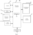
- Fig. 4 is a block diagram of in intelligent flight device 400 according to an exemplary embodiment.
- the intelligent flight device may be a unmanned camera and so on.
- the intelligent flight device 400 may include one or more of the following components: a processing component 402, a memory 404, a power component 406, a multimedia component 408, an audio component 410, an input/output (I/O) interface 412, a sensor component 414, and a communication component 416.
- the processing component 402 typically controls overall operations of the intelligent flight device 400, such as the operations associated with display, telephone calls, data communications, camera operations, and recording operations.
- the processing component 402 may include one or more processors 420 to execute instructions to perform all or part of the steps in the above described methods.
- the processing component 402 may include one or more modules which facilitate the interaction between the processing component 402 and other components.
- the processing component 402 may include a multimedia module to facilitate the interaction between the multimedia component 408 and the processing component 402.
- the memory 404 is configured to store various types of data to support the operation of the device 400. Examples of such data include instructions for any applications or methods operated on the intelligent flight device 400, contact data, phonebook data, messages, pictures, video, etc.
- the memory 404 may be implemented using any type of volatile or non-volatile memory devices, or a combination thereof, such as a static random access memory (SRAM), an electrically erasable programmable read-only memory (EEPROM), an erasable programmable read-only memory (EPROM), a programmable read-only memory (PROM), a read-only memory (ROM), a magnetic memory, a flash memory, a magnetic or optical disk.
- SRAM static random access memory
- EEPROM electrically erasable programmable read-only memory
- EPROM erasable programmable read-only memory
- PROM programmable read-only memory
- ROM read-only memory
- magnetic memory a magnetic memory
- flash memory a flash memory
- magnetic or optical disk a magnetic
- the power component 406 provides power to various components of the intelligent flight device 400.
- the power component 406 may include a power management system, one or more power sources, and any other components associated with the generation, management, and distribution of power in the intelligent flight device 400.
- the multimedia component 408 includes a screen providing an output interface between the intelligent flight device 400 and the user.
- the screen may include a liquid crystal display (LCD) and a touch panel (TP). If the screen includes the touch panel, the screen may be implemented as a touch screen to receive input signals from the user.
- the touch panel includes one or more touch sensors to sense touches, swipes, and gestures on the touch panel. The touch sensors may not only sense a boundary of a touch or swipe action, but also sense a period of time and a pressure associated with the touch or swipe action.
- the multimedia component 408 includes a front camera and/or a rear camera.
- the front camera and/or the rear camera may receive an external multimedia datum while the device 400 is in an operation mode, such as a photographing mode or a video mode.
- an operation mode such as a photographing mode or a video mode.
- Each of the front camera and the rear camera may be a fixed optical lens system or have focus and optical zoom capability.
- the audio component 410 is configured to output and/or input audio signals.
- the audio component 410 includes a microphone ("MIC") configured to receive an external audio signal when the intelligent flight device 400 is in an operation mode, such as a call mode, a recording mode, and a voice recognition mode.
- the received audio signal may be further stored in the memory 404 or transmitted via the communication component 416.
- the audio component 410 further includes a speaker to output audio signals.
- the I/O interface 412 provides an interface between the processing component 402 and peripheral interface modules, such as a keyboard, a click wheel, buttons, and the like.
- the buttons may include, but are not limited to, a home button, a volume button, a starting button, and a locking button.
- the sensor component 414 includes one or more sensors to provide status assessments of various aspects of the intelligent flight device 400. For instance, the sensor component 414 may detect an open/closed status of the intelligent flight device 400, relative positioning of components, e.g., the display and the keypad, of the intelligent flight device 400, a change in position of the device 400 or a component of the intelligent flight device 400, a presence or absence of user contact with the intelligent flight device 400, an orientation or an acceleration/deceleration of the intelligent flight device 400, and a change in temperature of the intelligent flight device 400.
- the sensor component 414 may include a proximity sensor configured to detect the presence of nearby objects without any physical contact.
- the sensor component 414 may also include a light sensor, such as a CMOS or CCD image sensor, for use in imaging applications.
- the sensor component 414 may also include an accelerometer sensor, a gyroscope sensor, a magnetic sensor, a pressure sensor, or a temperature sensor.
- the communication component 416 is configured to facilitate communication, wired or wirelessly, between the intelligent flight device 400 and other devices.
- the intelligent flight device 400 can access a wireless network based on a communication standard, such as WiFi, 2G, or 3G, or a combination thereof.
- the communication component 416 receives a broadcast signal or broadcast associated information from an external broadcast management system via a broadcast channel.
- the communication component 416 further includes a near field communication (NFC) module to facilitate short-range communications.
- the NFC module may be implemented based on a radio frequency identification (RFID) technology, an infrared data association (IrDA) technology, an ultra-wideband (UWB) technology, a Bluetooth (BT) technology, and other technologies.
- RFID radio frequency identification
- IrDA infrared data association
- UWB ultra-wideband
- BT Bluetooth
- the intelligent flight device 400 may be implemented with one or more application specific integrated circuits (ASICs), digital signal processors (DSPs), digital signal processing devices (DSPDs), programmable logic devices (PLDs), field programmable gate arrays (FPGAs), controllers, micro-controllers, microprocessors, or other electronic components, for performing the above described methods.
- ASICs application specific integrated circuits
- DSPs digital signal processors
- DSPDs digital signal processing devices
- PLDs programmable logic devices
- FPGAs field programmable gate arrays
- controllers micro-controllers, microprocessors, or other electronic components, for performing the above described methods.
- non-transitory computer-readable storage medium including instructions, such as the memory 404 including instructions, the above instructions are executable by the processor 420 in the intelligent flight device 400, for performing the above-described methods.
- the non-transitory computer-readable storage medium may be a ROM, a RAM, a CD-ROM, a magnetic tape, a floppy disc, an optical data storage device, and the like.
- a non-transitory computer-readable storage medium when the instructions in the storage medium are executed by the processor of the intelligent flight device 400, the intelligent flight device 400 is caused to perform the photographing method for the intelligent flight device as shown in Fig. 1 or 2A .
Landscapes
- Engineering & Computer Science (AREA)
- Multimedia (AREA)
- Signal Processing (AREA)
- Physics & Mathematics (AREA)
- General Physics & Mathematics (AREA)
- Radar, Positioning & Navigation (AREA)
- Remote Sensing (AREA)
- Aviation & Aerospace Engineering (AREA)
- Automation & Control Theory (AREA)
- Studio Devices (AREA)
- Circuit Arrangement For Electric Light Sources In General (AREA)
- Control Of Position, Course, Altitude, Or Attitude Of Moving Bodies (AREA)
Abstract
Description
- The present disclosure relates to the technologies of electronic devices, and more particularly, to a photographing method for an intelligent flight device and the intelligent flight device.
- As with fast-developing technologies of electronic devices, various intelligent flight devices emerge, for example, unmanned cameras, which can fly to a great height to photograph scenes and objects on the ground under control of devices such as a remote control.
- However, in practical applications, when photographing is conducted using an intelligent flight device under an environment where there is a light source, the light rays emitted from the light source will travel by the intelligent flight device to generate a projection. For example, when the photographing is conducted using a unmanned camera in a sunny day, due to the illumination of the sun, a projection of the unmanned camera may be generated on the ground, and under such situation the generated projection is inclined to be incorporated into the photographed pictures or videos.
- In order to solve the problems in the related art, the present disclosure provides a photographing method for an intelligent flight device and an intelligent flight device.
- According to a first aspect of the present invention, there is provided a photographing method for an intelligent flight device. The method includes:
- determining a light source angle, wherein the light source angle is an angle between a current beam direction of a target light source and a vertical direction, the target light source is a light source capable of generating a projection of the intelligent flight device, and the vertical direction is a direction perpendicular to a horizontal plane;
- according to the light source angle, determining a bearing of a projection on the horizontal plane which is generated by travel of the light emitted from the target light source passing the intelligent flight device; and
- performing photographing based on a current photographing angle of the intelligent flight device and the bearing of the projection.
- Optionally, the determining the light source angle includes any one of:
- determining, based on a plurality of first preset angles, a plurality of light intensities by use of a configured light sensor and determining a first preset angle corresponding to a maximum light intensity as the light source angle, wherein the plurality of first preset angles correspond to the plurality of light intensities one to one; and
- determining, based on a plurality of second preset angles, a plurality of exposures, and determining a second preset angle corresponding to a maximum exposure as the light source angle, wherein the plurality of second preset angles correspond to the plurality of exposures one to one.
- Optionally, the determining the bearing of the projection on the horizontal plane which is generated by travel of the light emitted from the target light source passing the intelligent flight device according to the light source angle, includes:
- if the light source angle is equal to zero, determining that the projection on the horizontal plane which is generated by travel of the light emitted from the target light source passing the intelligent flight device is right below a current position of the intelligent flight device; and
- if the light source angle is not equal to zero, determining a flight height, and according to the light source angle and the flight height, determining the bearing of the projection on the horizontal plane which is generated by travel of the light emitted from the target light source passing the intelligent flight device, wherein the flight height is a current height of the intelligent flight device from the horizontal plane.
- Optionally, performing photographing based on the current photographing angle of the intelligent flight device and the bearing of the projection, includes:
- based on the current photographing angle and the bearing of the projection, determining whether the bearing of the projection is within a photographing range;
- if the bearing of the projection is within the photographing range and is right below the current position of the intelligent flight device, performing photographing downwards in the vertical direction to obtain a photographed picture;
- by performing a preset image process on the photographed picture, determining a size of the intelligent flight device in the photographed picture;
- based on the size of the intelligent flight device in the photographed picture and the flight height, determining a rotation angle which is an angle for avoiding the projection; and
- performing photographing based on the rotation angle.
- Optionally, determining whether the bearing of the projection is within the photographing range based on the current photographing angle and the bearing of the projection, includes:
- if the bearing of the projection is within the photographing range and the light source angle is not equal to zero, determining a target direction according to the bearing of the projection, wherein the target direction is any direction other than an direction in which the bearing of the projection is;
- determining, from a plurality of preset projection ranges, a preset projection range with a projection distance, wherein the projection distance is a horizontal distance between the bearing of the projection and the intelligent flight device;
- determining, from a plurality of preset rotation angles, a preset rotation angel corresponding to the present projection range with the projection distance, wherein the plurality of preset rotation angles correspond to the plurality of preset projection ranges one to one;
- wherein performing photographing based on the current photographing angle and the bearing of the projection includes:
- performing photographing based on the target direction and the preset rotation angle corresponding to the preset projection range with the projection distance.
- According to another aspect of the present invention, there is provided an intelligent flight device, including:
- a first determination module configured to determine a light source angle, wherein the light source angle is an angle between a current beam direction of a target light source and a vertical direction, the target light source is a light source capable of generating a projection of the intelligent flight device, and the vertical direction is a direction perpendicular to a horizontal plane;
- a second determination module configured to, according to the light source angle determined by the first determination module, determine a bearing of a projection on the horizontal plane which is generated by travel of the light emitted from the target light source passing the intelligent flight device; and
- a photographing module configured to perform photographing based on a current photographing angle of the intelligent flight device and the bearing of the projection determined by the second determination module.
- Optionally, the first determination module includes:
- a first determination sub-module configured to determine, based on a plurality of first preset angles, a plurality of light intensities by use of a configured light sensor and determine a first preset angle corresponding to a maximum light intensity as the light source angle, wherein the plurality of first preset angles correspond to the plurality of light intensities one to one; and
- a second determination sub-module configured to determine, based on a plurality of second preset angles, a plurality of exposures, and determine a second preset angle corresponding to a maximum exposure as the light source angle, wherein the plurality of second preset angles correspond to the plurality of exposures one to one.
- Optionally, the second determination module includes:
- a third determination sub-module configured to, if the light source angle is equal to zero, determine that the projection on the horizontal plane which is generated by travel of the light emitted from the target light source passing the intelligent flight device is right below a current position of the intelligent flight device; and
- a fourth determination sub-module configured to, if the light source angle is not equal to zero, determine a flight height, and according to the light source angle and the flight height, determine the bearing of the projection on the horizontal plane which is generated by travel of the light emitted from the target light source passing the intelligent flight device, wherein the flight height is a current height of the intelligent flight device from the horizontal plane.
- Optionally, the photographing module includes:
- a determination sub-module configured to, based on the current photographing angle and the bearing of the projection, determine whether the bearing of the projection is within a photographing range;
- a first photographing sub-module configured to, if the bearing of the projection is within the photographing range and is right below the current position of the intelligent flight device, perform photographing downwards in the vertical direction to obtain a photographed picture;
- a fifth determination sub-module configured to, by performing of a preset image process on the photographed picture, determine a size of the intelligent flight device in the photographed picture;
- a sixth determination sub-module configured to, based on the size of the intelligent flight device in the photographed picture and the flight height, determine a rotation angle which is an angle for avoiding the projection; and
- a second photographing sub-module configured to perform photographing based on the rotation angle.
- Optionally, the photographing module further includes:
- a seventh determination sub-module configured to, if the bearing of the projection is within the photographing range and the light source angle is not equal to zero, determine a target direction according to the bearing of the projection, wherein the target direction is any direction other than an direction in which the bearing of the projection is;
- an eighth determination sub-module configured to, determine, from a plurality of preset projection ranges, a preset projection range with a projection distance, wherein the projection distance is a horizontal distance between the bearing of the projection and the intelligent flight device; and
- a ninth determination sub-module configured to determine, from a plurality of preset rotation angles, a preset rotation angel corresponding to the present projection range with the projection distance, wherein the plurality of preset rotation angles correspond to the plurality of preset projection ranges one to one;
- wherein the second photographing sub-module is configured to:
- perform photographing based on the target direction and the preset rotation angle corresponding to the preset projection range with the projection distance
- According to a third aspect of the present disclosureinvention, there is provided an intelligent flight device, including:
- a processor; and
- a memory for storing instructions executable by the processor;
- wherein the processor is configured to:
- determine a light source angle, wherein the light source angle is an angle between a current beam direction of a target light source and a vertical direction, the target light source is a light source capable of generating a projection of the intelligent flight device, and the vertical direction is a direction perpendicular to a horizontal plane;
- according to the light source angle, determine a bearing of a projection on the horizontal plane which is generated by travel of the light emitted from the target light source passing the intelligent flight device; and
- perform photographing based on a current photographing angle of the intelligent flight device and the bearing of the projection.
- According to a fourth aspect of the present invention, there is provided a computer program, which when executing on a processor, performs any one of the above methods.
- The technical solutions provided by embodiments of the present disclosure may have the following advantageous effects:
- An angle between a current beam direction of a target light source which is a light source capable of generating a projection of an intelligent flight device and a vertical direction is determined; according to the determined angle, a bearing of a projection on the horizontal plane which is generated by travel of the light emitted from the target light source passing the intelligent flight device can be determined. Since the bearing of the projection is determined, photographing can be performed based on a current photographing angle of the intelligent flight device and the bearing of the projection. Thus, the technical solutions in the present disclosure can avoid incorporation of the projection into the photographed pictures or videos, thereby improving the quality of photographing.
- It is to be understood that both the foregoing general description and the following detailed description are exemplary and explanatory only and are not restrictive of the invention, as claimed.
- The accompanying drawings, which are incorporated in and constitute a part of this specification, illustrate embodiments consistent with the invention and, together with the description, serve to explain the principles of the invention.
-
Fig. 1 is a flow chart of a photographing method for an intelligent flight device according to an exemplary embodiment. -
Fig. 2A is a flow chart of a photographing method for an intelligent flight device according to another exemplary embodiment. -
Fig. 2B is a schematic diagram showing an implementation environment involved in the photographing method for an intelligent flight device as shown inFig. 2A . -
Fig. 2C is a schematic diagram showing another implementation environment involved in the photographing method for an intelligent flight device as shown inFig. 2A . -
Fig. 3 is a block diagram showing an intelligent flight device according to another exemplary embodiment. -
Fig. 4 is a block diagram showing anintelligent flight device 400 according to another exemplary embodiment. - Reference will now be made in detail to exemplary embodiments, examples of which are illustrated in the accompanying drawings. The following description refers to the accompanying drawings in which the same numbers in different drawings represent the same or similar elements unless otherwise represented. The implementations set forth in the following description of exemplary embodiments do not represent all implementations consistent with the invention. Instead, they are merely examples of apparatuses and methods consistent with aspects related to the invention as recited in the appended claims.
- Prior to detailed description of embodiments of the present disclosure, the application scenarios of embodiments of the present disclosure will be described first. In related arts, when photographing is conducted using an intelligent flight device under an environment where there is a light source, the light rays emitted from the light source will travel by the intelligent flight device to generate a projection, and under such condition the generated projection is inclined to be incorporated into the photographed pictures or videos, which may influence the quality of photographing. In view of this, embodiments of the present disclosure provide a photographing method for an intelligent flight device which is capable of avoiding incorporation of the projection into the photographed pictures or videos and thus improving the quality of photographing. The photographing method for an intelligent provided by embodiments of the present disclosure may be executed by the intelligent flight device which may be an unmanned camera and the like.
-
Fig. 1 is a flow chart of a photographing method for an intelligent flight device according to an exemplary embodiment. As shown inFig. 1 , the photographing for an intelligent flight device may include the following steps. - In
step 101, a light source angle is determined. The light source angle is an angle between a current beam direction of a target light source and a vertical direction, the target light source is a light source capable of generating a projection of the intelligent flight device, and the vertical direction is a direction perpendicular to a horizontal plane. - In
step 102, according to the light source angle, a bearing of a projection on the horizontal plane which is generated by travel of the light emitted from the target light source passing the intelligent flight device is determined. - In
step 103, photographing is performed based on a current photographing angle of the intelligent flight device and the bearing of the projection. - In the embodiment of the present disclosure, an angle between a current beam direction of a target light source which is a light source capable of generating a projection of an intelligent flight device and a vertical direction is determined; according to the determined angle, a bearing of a projection on the horizontal plane which is generated by travel of the light emitted from the target light source passing the intelligent flight device can be determined. Since the bearing of the projection is determined, photographing can be performed based on a current photographing angle of the intelligent flight device and the bearing of the projection. Thus, the technical solutions in the embodiment can avoid incorporation of the projection into the photographed pictures or videos, thereby improving the quality of photographing.
- Optionally, the determining the light source angle includes any one of:
- determining, based on a plurality of first preset angles, a plurality of light intensities by use of a configured light sensor and determining a first preset angle corresponding to a maximum light intensity as the light source angle, wherein the plurality of first preset angles correspond to the plurality of light intensities one to one; and
- determining, based on a plurality of second preset angles, a plurality of exposures, and determining a second preset angle corresponding to a maximum exposure as the light source angle, wherein the plurality of second preset angles correspond to the plurality of exposures one to one.
- Optionally, the determining the bearing of the projection on the horizontal plane which is generated by travel of the light emitted from the target light source passing the intelligent flight device according to the light source angle, includes:
- if the light source angle is equal to zero, determining that the projection on the horizontal plane which is generated by travel of the light emitted from the target light source passing the intelligent flight device is right below a current position of the intelligent flight device; and
- if the light source angle is not equal to zero, determining a flight height, and according to the light source angle and the flight height, determining the bearing of the projection on the horizontal plane which is generated by travel of the light emitted from the target light source passing the intelligent flight device, wherein the flight height is a current height of the intelligent flight device from the horizontal plane.
- Optionally, performing photographing based on the current photographing angle of the intelligent flight device and the bearing of the projection, includes:
- based on the current photographing angle and the bearing of the projection, determining whether the bearing of the projection is within a photographing range;
- if the bearing of the projection is within the photographing range and is right below the current position of the intelligent flight device, performing photographing downwards in the vertical direction to obtain a photographed picture;
- by performing a preset image process on the photographed picture, determining a size of the intelligent flight device in the photographed picture;
- based on the size of the intelligent flight device in the photographed picture and the flight height, determining a rotation angle which is an angle for avoiding the projection; and
- performing photographing based on the rotation angle.
- Optionally, determining whether the bearing of the projection is within the photographing range based on the current photographing angle and the bearing of the projection, includes:
- if the bearing of the projection is within the photographing range and the light source angle is not equal to zero, determining a target direction according to the bearing of the projection, wherein the target direction is any direction other than an direction in which the bearing of the projection is;
- determining, from a plurality of preset projection ranges, a preset projection range with a projection distance, wherein the projection distance is a horizontal distance between the bearing of the projection and the intelligent flight device;
- determining, from a plurality of preset rotation angles, a preset rotation angel corresponding to the present projection range with the projection distance, wherein the plurality of preset rotation angles correspond to the plurality of preset projection ranges one to one;
- wherein performing photographing based on the current photographing angle and the bearing of the projection includes:
- performing photographing based on the target direction and the preset rotation angle corresponding to the preset projection range with the projection distance.
- All of the above optional technical solutions can be combined with each other arbitrarily to constitute an alternative embodiment of the present disclosure, and embodiments of the present disclosure do not intend to describe one by one.
-
Fig. 2A is a flow chart of a photographing method for an intelligent flight device according to another exemplary embodiment. As shown inFig. 2A , the photographing method for an intelligent flight device may be applied in an intelligent control device. The photographing method for an intelligent flight device may include the following steps. - In
step 201, a light source angle is determined. The light source angle is an angle between a current beam direction of a target light source and a vertical direction, the target light source is a light source capable of generating a projection of the intelligent flight device, and the vertical direction is a direction perpendicular to a horizontal plane. - The target light source may include the sun, or a lighting device and the like, and embodiments of the present disclosure do not impose specific limitations on this. For example, referring to
Fig. 2B , the target light source inFig. 2B is thesun 21, and the angle between the current bearing of the targetlight source 21 and the vertical direction is α, i.e., the light source angle is α. The determination of the light source angle may be realized by use of any one of the following approaches: - In a first approach, based on a plurality of first preset angles, a plurality of light intensities are determined by use of a configured light sensor and a first preset angle corresponding to a maximum light intensity is determined as the light source angle. The plurality of first preset angles correspond to the plurality of light intensities one to one.
- The intelligent flight device may be provided with a light sensor. It is easy to understand that only when the height of the target light source from the horizontal plane is higher than the height of the intelligent flight device from the horizontal plane, the target light source may generate a projection of the intelligent flight device. Thus, in a possible implementation, the light sensor may be provided at the top of the intelligent flight device and can be rotated so as to collect the light emitted from the light source based on the plurality of first preset angles.
- Each of the plurality of first preset angles may be set by users according to actual needs, or may be set by the intelligent flight device by default, and embodiments of the present do not impose limitations on this.
- For example, the plurality of first preset angles may be preset angles of 30 degrees, 60 degrees, 90 degrees, -30 degrees and -60 degrees with respect to the vertical direction. To put another way, the intelligent flight device may collect light rays every 30 degrees by use of the light sensor to obtain the plurality of light intensities corresponding to the plurality of first preset angles.
- The higher a light intensity is, the closer the first preset angle corresponding to the light intensity gets to directly pointing to the target light source, i.e., the closer the first preset angle corresponding to the light intensity approaches the angle between the bearing of the target light source and the vertical direction. Thus, after obtaining the plurality of light intensities, the intelligent flight device determines from the plurality of light intensities a maximum light intensity, and determines a first preset angle corresponding to the maximum light intensity as the light source angle.
- In a second approach, based on a plurality of second preset angles, a plurality of exposures are determined, and a second preset angle corresponding to a maximum exposure is determined as the light source angle. The plurality of second preset angles correspond to the plurality of exposures one to one.
- In practical implementations, the intelligent flight device may collect light rays based on a plurality of second preset angles by means of a camera device of the intelligent flight device to determine a plurality of exposures. The higher an exposure is, the closer the second preset angle corresponding to the exposure approaches the angle between the bearing of the target light source and the vertical direction. The second preset angle corresponding to the maximum exposure is determined as the light source angle.
- Each of the plurality of first preset angles may be set by users according to actual needs, or may be set by the intelligent flight device by default, and embodiments of the present do not impose limitations on this.
- It should be noted that the above two approaches for determining the light source angle are exemplary, and in alternative embodiments, other approaches may be used to determine the light source angle. For example, any one of the following may be used.
- In a third approach, if the target light source is the sun, the intelligent flight device determines position information regarding the current position of the intelligent flight device using a positioning function and obtains a system time point; based on the position information and the system time point, the intelligent flight device obtains from a designated server a sun rising angle corresponding to the position information and the system time point. The sun rising angle is an angle between the sun and the horizontal plane, and a difference between 90 degrees and the sun rising angle is determined as the light source angle. The designated server stores a correspondence relationship of system time points and position information versus sun rising angles.
- In the approach, the intelligent flight device may determining the position information regarding the current position of the intelligent flight device and the system time point using a positioning technology such as Global Positioning System (GPS), and then the intelligent flight device sends to the designated server a light source angle obtaining request which carries the position information and the system time point. After receiving the light source angle obtaining request, the designated server extracts from the light source angle obtaining request the position information and the system time point, and obtains the sun rising angle corresponding to the position information and the system time point from the pre-stored correspondence relationship of system time points and position information versus sun rising angles, and sends the determined sun rising angle to the intelligent flight device. Because the sun rising angle can be approximately deemed as the angle between the intelligent flight device and the horizontal plane, the intelligent flight device determines the angle obtained by subtracting the sun rising angle from 90 degrees as the light source angle.
- In a fourth approach, the light source angle is determined by capturing a projection of an object which is of a dimension the same with that of the intelligent flight device.
- In the approach, the intelligent flight device may photograph an object and the projection of the object. The object is within the same space with the intelligent flight device and at the same height with the intelligent flight device. The intelligent flight device may determine the light source angle according to the projection of the object and the current flight height of the intelligent flight device. Specifically, the determination of the light source angle may be based on the pythagorean theorem of a triangle, and detailed descriptions will be omitted here.
- It should be noted that in the above embodiments the light source angle is determined by the intelligent flight device, and in alternative embodiments, an intelligent terminal or a smart terminal which is associated with the intelligent flight device may obtain the light source angle and then send the light source angel to the intelligent flight device, and embodiments of the present disclosure do not impose specific limitations on this.
- In
step 202, according to the to the light source angle, a bearing of a projection on the horizontal plane which is generated by travel of the light emitted from the target light source passing the intelligent flight device is determined. - Depending on the light source angle, the bearing of the projection on the horizontal plane which is generated by travel of the light emitted from the target light source passing the intelligent flight device may be determined using the following approaches.
- In a first approach, if the light source angle is equal to zero, it is determined that the projection on the horizontal plane which is generated by travel of the light emitted from the target light source passing the intelligent flight device is right below a current position of the intelligent flight device.
- Referring to
Fig. 2C , if the light source angle is equal to zero, theprojection 22 on the horizontal plane which is generated by travel of the light emitted from the targetlight source 21 passing theintelligent flight device 23 is right below the current position of theintelligent flight device 23. - In a second approach, if the light source angle is not equal to zero, a flight height is determined, and according to the light source angle and the flight height, the bearing of the projection on the horizontal plane which is generated by travel of the light emitted from the target light source passing the intelligent flight device is determined. The flight height is a current height of the intelligent flight device from the horizontal plane.
- Referring to
Fig. 2B , if the flight height is H, because the light source angle α is known, the bearing d of the projection on the horizontal plane which is generated by travel of the light emitted from the target light source passing the intelligent flight device may be determined according to the formula: tan α=d/H. - In a possible implementation, the intelligent flight device may determine the flight height using a distance measuring device such as an infrared sensor provided on the intelligent flight device, and embodiments of the present disclosure do not impose specific limitations on this.
- In
step 203, photographing is performed based on a current photographing angle of the intelligent flight device and the bearing of the projection. - In a possible implementation, the intelligent flight device may determine the current photographing angle by an angle sensor provided on the intelligent flight device. That is, when the camera device of the intelligent flight device is rotated, the rotation angle of the camera device may be obtained using the angle sensor so as to obtain the current photographing angle.
- Then, based on the current photographing angle and the bearing of the projection, the intelligent flight device determines whether the bearing of the projection is within a photographing range.
- In a possible implementation, the determination of whether the bearing of the projection is within a photographing range may be realized using the following procedure: determining whether a photographing direction corresponding to the current photographing angle is the same with the direction in which the bearing of the projection is; if the photographing direction corresponding to the current photographing angle is different from the direction in which the bearing of the projection is, determining that the bearing of the projection is not within the photographing range; if the photographing direction corresponding to the current photographing angle is the same with the direction in which the bearing of the projection is, determining whether an angle between the photographing angle and the vertical direction is smaller than the light source angle; if the angle between he photographing angle and the vertical direction is smaller than the light source angle, determining that the bearing of the projection is within the photographing range; if the angle between the photographing angle and the vertical direction is greater than or equal to the light source angle, determining that the bearing of the projection is not within the photographing range.
- For example, referring to
Fig. 2B , if the current photographing angle is towards right, because the bearing of the projection (the bearing of the projection is towards left on the horizontal plane) is opposite to the photographing direction corresponding to the photographing angle, it is apparent that the bearing of the projection is not within the photographing range. On the contrary, if the photographing direction corresponding to the current photographing angle is the same with the bearing of the projection, and the angle between the current photographing angle and the vertical direction is smaller than the light source angle, for example, if the current photographing angle is towards left and the angle between the current photographing angel and the vertical direction is equal to 20 degrees and the light source angle is equal to 60 degrees, the intelligent flight device may determine that the bearing of the projection is within the photographing range. - It should be noted that in the above embodiments the intelligent flight device determines whether the bearing of the projection is within the photographing range based on the current photographing angle and the bearing of the projection, and in alternative embodiments, the intelligent flight device may send the current photographing angle and the bearing of the projection to an intelligent device which as associated with the intelligent flight device, for example, a mobile phone or a smart remote control, so that the intelligent device may determine whether the bearing of the projection is within the photographing range based on the current photographing angle and the bearing of the projection, and embodiments of the present disclosure do not impose specific limitations on this.
- If the bearing of the projection is within the photographing range, the intelligent flight device should conduct photographing by avoiding the projection. Specific implementations may include any one of the following.
- In a first approach, if the bearing of the projection is within the photographing range and is right below the current position of the intelligent flight device, photographing is performed downwards in the vertical direction to obtain a photographed picture; by performing of a preset image process on the photographed picture, a size of the intelligent flight device in the photographed picture is determined; based on the size of the intelligent flight device in the photographed picture and the flight height, a rotation angle which is an angle for avoiding the projection is determined; and photographing is performed based on the rotation angle.
- If the bearing of the projection is right below the current position of the intelligent flight device, the camera device may be rotated by a certain angle to conduct photographing by avoiding the projection. Referring to
Fig. 2C , if the camera device is rotated by an angle of β towards any direction, photographing the projection into the photographed pictures or videos can be avoided. Thus, the angle β needs to be determined. - Accordingly, in the embodiment of the present disclosure, the projection is photographed to obtain the photographed picture. Because the intelligent flight device generally includes a plurality of arms which are used for fly assistance, and based on such feature, a circle region where the projection is located may be obtained based on the projection. As shown in
Fig. 2C , the intelligent flight device may perform a preset image process on the photographed picture to determine the size of the intelligent flight device in the photographed picture, and thus the radius r of the circle region in the photographed picture where the intelligent flight device is can be obtained. Next, based on the radius r and the flight height H and tan β = r/H, the intelligent flight device may determine the above rotation angle β. - It should be noted that the radius r and the flight height may be in different units, and thus in practical implementations unit conversion may be needed, and detailed descriptions are omitted here.
- The above preset image process may include processes such as image normalization, or pixel point scan and the like, and embodiments of the present disclosure do not impose specific limitations on this.
- In a second approach, if the bearing of the projection is within the photographing range and the light source angle is not equal to zero, a target direction is determined according to the bearing of the projection; the target direction is any direction other than an direction in which the bearing of the projection is; from a plurality of preset projection ranges, a preset projection range with a projection distance is determined, and the projection distance is a horizontal distance between the bearing of the projection and the intelligent flight device; from a plurality of preset rotation angles, a preset rotation angel corresponding to the present projection range with the projection distance is determined, and the plurality of preset rotation angles correspond to the plurality of preset projection ranges one to one; photographing is performed based on the target direction and the preset rotation angle corresponding to the preset projection range with the projection distance.
- Each of the preset projection ranges may be set by users according to actual needs, or may be set by the intelligent flight device by default, and embodiments of the present disclosure do not impose specific limitations on this.
- Also, each of the preset rotation angles may be set by users according to actual needs, or may be set by the intelligent flight device by default, and embodiments of the present disclosure do not impose specific limitations on this.
- When the bearing of the projection is within the photographing range and the light source angle is not equal to zero, if photographing is directly performed, the projection may be photographed into the photographed pictures or videos, and thus the photographing angle may be adjusted. Referring to
Fig. 2B , if the bearing of the projection is as indicated by thereference number 22, the camera device needs to be rotated by a preset rotation angle towards any direction other than the direction in which the bearing of the projection is. - Under such condition, the rotation angle is related to the horizontal distance between the bearing of the projection and the intelligent flight device. The larger the horizontal distance between the bearing of the projection and the intelligent flight device is, the smaller the projection formed on the horizontal plane generated by the travel of the light from the target light source passing the intelligent flight device will be. Thus, the preset rotation angle may be set as a small value, that is, the photographing of the projection into the photographed pictures or videos can be avoided by rotating only a small angle. On the contrary, the smaller the horizontal distance between the bearing of the projection and the intelligent flight device is, the larger the projection formed on the horizontal plane generated by the travel of the light from the target light source passing the intelligent flight device will be. Thus, in order to avoid the projection to conduct photographing, a relatively large preset rotation angle is needed.
- In a possible implementation, the one-to-one correspondence relationship between the plurality of preset projection ranges and the plurality of preset rotation angles may be determined by users according to a large volume of test data, and the one-to-one correspondence relationship between the plurality of preset projection ranges and the plurality of preset rotation angles may be stored in the intelligent flight device.
- It should be noted that the target direction is any direction other than the direction in which the bearing of the projection is, and users can set the target direction according to their preferences, and store the target direction in association with a user account; and then, based on the correspondence relationship between target directions and user accounts, the intelligent flight device may select a target direction corresponding to a user account and thus user experience may be improved.
- In addition, in the above implementation, after the intelligent flight device is rotated by a preset angle towards the target direction, it is possible that the scenes and objects in the bearing of the projection cannot be photographed. In order to continue photographing of the scenes and objects in the bearing of the projection, after the intelligent flight device is rotated by the preset rotation angle towards the target direction, a photographing path may be planned according to the bearing of the projection and the target direction. For example, referring to
Fig. 2B , if the intelligent flight device is rotated by a preset rotation angle towards right in the horizontal direction, the intelligent flight device may fly towards left in the horizontal direction. At this time, the projection of the intelligent flight device moves as the intelligent flight device flies, the bearing of the projection moves accordingly towards left in the horizontal direction, and thus the intelligent flight device may photograph the scenes and objects in the bearing of the projection. - It should be noted that after planning the photographing path, the intelligent flight device may send the photographing path to an intelligent device such as a mobile phone or a remote control and the like. After receiving the photographing path, the intelligent device may present the photographing path, so that users may know the next photograph path of the intelligent flight device, thereby improving user experience.
- In embodiments of the present disclosure, an angle between a current beam direction of a target light source which is a light source capable of generating a projection of an intelligent flight device and a vertical direction is determined; according to the determined angle, a bearing of a projection on the horizontal plane which is generated by travel of the light emitted from the target light source passing the intelligent flight device can be determined. Since the bearing of the projection is determined, photographing can be performed based on a current photographing angle of the intelligent flight device and the bearing of the projection. Thus, the technical solutions in the present disclosure can avoid incorporation of the projection into the photographed pictures or videos, thereby improving the quality of photographing.
-
Fig. 3 is a block diagram of an intelligent flight device according to another exemplary embodiment. As shown inFig. 3 , the intelligent flight device includes afirst determination module 310, asecond determination module 320 and a photographingmodule 330. - The
first determination module 310 is configured to determine a light source angle, the light source angle is an angle between a current beam direction of a target light source and a vertical direction, the target light source is a light source capable of generating a projection of the intelligent flight device, and the vertical direction is a direction perpendicular to a horizontal plane. - The
second determination module 320 is configured to, according to the light source angle determined by thefirst determination module 310, determine a bearing of a projection on the horizontal plane which is generated by travel of the light emitted from the target light source passing the intelligent flight device. - The photographing
module 330 is configured to perform photographing based on a current photographing angle of the intelligent flight device and the bearing of the projection determined by thesecond determination module 320. - Optionally, the
first determination module 310 includes: - a first determination sub-module configured to determine, based on a plurality of first preset angles, a plurality of light intensities by use of a configured light sensor and determine a first preset angle corresponding to a maximum light intensity as the light source angle, wherein the plurality of first preset angles correspond to the plurality of light intensities one to one; and
- a second determination sub-module configured to determine, based on a plurality of second preset angles, a plurality of exposures, and determine a second preset angle corresponding to a maximum exposure as the light source angle, wherein the plurality of second preset angles correspond to the plurality of exposures one to one.
- Optionally, the
second determination module 320 includes: - a third determination sub-module configured to, if the light source angle is equal to zero, determine that the projection on the horizontal plane which is generated by travel of the light emitted from the target light source passing the intelligent flight device is right below a current position of the intelligent flight device; and
- a fourth determination sub-module configured to, if the light source angle is not equal to zero, determine a flight height, and according to the light source angle and the flight height, determine the bearing of the projection on the horizontal plane which is generated by travel of the light emitted from the target light source passing the intelligent flight device, wherein the flight height is a current height of the intelligent flight device from the horizontal plane.
- Optionally, the photographing
module 330 includes: - a determination sub-module configured to, based on the current photographing angle and the bearing of the projection, determine whether the bearing of the projection is within a photographing range;
- a first photographing sub-module configured to, if the bearing of the projection is within the photographing range and is right below the current position of the intelligent flight device, perform photographing downwards in the vertical direction to obtain a photographed picture;
- a fifth determination sub-module configured to, by performing of a preset image process on the photographed picture, determine a size of the intelligent flight device in the photographed picture;
- a sixth determination sub-module configured to, based on the size of the intelligent flight device in the photographed picture and the flight height, determine a rotation angle which is an angle for avoiding the projection; and
- a second photographing sub-module configured to perform photographing based on the rotation angle.
- Optionally, the photographing
module 330 further includes: - a seventh determination sub-module configured to, if the bearing of the projection is within the photographing range and the light source angle is not equal to zero, determine a target direction according to the bearing of the projection, wherein the target direction is any direction other than an direction in which the bearing of the projection is;
- an eighth determination sub-module configured to determine, from a plurality of preset projection ranges, a preset projection range with a projection distance, wherein the projection distance is a horizontal distance between the bearing of the projection and the intelligent flight device; and
- a ninth determination sub-module configured to determine, from a plurality of preset rotation angles, a preset rotation angel corresponding to the present projection range with the projection distance, wherein the plurality of preset rotation angles correspond to the plurality of preset projection ranges one to one;
- the second photographing sub-module is configured to:
- perform photographing based on the target direction and the preset rotation angle corresponding to the preset projection range with the projection distance.
- In the embodiment of the present disclosure, an angle between a current beam direction of a target light source which is a light source capable of generating a projection of an intelligent flight device and a vertical direction is determined; according to the determined angle, a bearing of a projection on the horizontal plane which is generated by travel of the light emitted from the target light source passing the intelligent flight device can be determined. Since the bearing of the projection is determined, photographing can be performed based on a current photographing angle of the intelligent flight device and the bearing of the projection. Thus, the technical solutions in the embodiment can avoid incorporation of the projection into the photographed pictures or videos, thereby improving the quality of photographing.
- With respect to the device embodiments, the specific manners for the individual modules to perform operations can be found in the previous detailed descriptions regarding the method embodiments and repeated descriptions are omitted here.
-
Fig. 4 is a block diagram of inintelligent flight device 400 according to an exemplary embodiment. For example, the intelligent flight device may be a unmanned camera and so on. - Referring to
Fig. 4 , theintelligent flight device 400 may include one or more of the following components: aprocessing component 402, amemory 404, apower component 406, amultimedia component 408, anaudio component 410, an input/output (I/O) interface 412, asensor component 414, and acommunication component 416. - The
processing component 402 typically controls overall operations of theintelligent flight device 400, such as the operations associated with display, telephone calls, data communications, camera operations, and recording operations. Theprocessing component 402 may include one ormore processors 420 to execute instructions to perform all or part of the steps in the above described methods. Moreover, theprocessing component 402 may include one or more modules which facilitate the interaction between theprocessing component 402 and other components. For instance, theprocessing component 402 may include a multimedia module to facilitate the interaction between themultimedia component 408 and theprocessing component 402. - The
memory 404 is configured to store various types of data to support the operation of thedevice 400. Examples of such data include instructions for any applications or methods operated on theintelligent flight device 400, contact data, phonebook data, messages, pictures, video, etc. Thememory 404 may be implemented using any type of volatile or non-volatile memory devices, or a combination thereof, such as a static random access memory (SRAM), an electrically erasable programmable read-only memory (EEPROM), an erasable programmable read-only memory (EPROM), a programmable read-only memory (PROM), a read-only memory (ROM), a magnetic memory, a flash memory, a magnetic or optical disk. - The
power component 406 provides power to various components of theintelligent flight device 400. Thepower component 406 may include a power management system, one or more power sources, and any other components associated with the generation, management, and distribution of power in theintelligent flight device 400. - The
multimedia component 408 includes a screen providing an output interface between theintelligent flight device 400 and the user. In some embodiments, the screen may include a liquid crystal display (LCD) and a touch panel (TP). If the screen includes the touch panel, the screen may be implemented as a touch screen to receive input signals from the user. The touch panel includes one or more touch sensors to sense touches, swipes, and gestures on the touch panel. The touch sensors may not only sense a boundary of a touch or swipe action, but also sense a period of time and a pressure associated with the touch or swipe action. In some embodiments, themultimedia component 408 includes a front camera and/or a rear camera. The front camera and/or the rear camera may receive an external multimedia datum while thedevice 400 is in an operation mode, such as a photographing mode or a video mode. Each of the front camera and the rear camera may be a fixed optical lens system or have focus and optical zoom capability. - The
audio component 410 is configured to output and/or input audio signals. For example, theaudio component 410 includes a microphone ("MIC") configured to receive an external audio signal when theintelligent flight device 400 is in an operation mode, such as a call mode, a recording mode, and a voice recognition mode. The received audio signal may be further stored in thememory 404 or transmitted via thecommunication component 416. In some embodiments, theaudio component 410 further includes a speaker to output audio signals. - The I/O interface 412 provides an interface between the
processing component 402 and peripheral interface modules, such as a keyboard, a click wheel, buttons, and the like. The buttons may include, but are not limited to, a home button, a volume button, a starting button, and a locking button. - The
sensor component 414 includes one or more sensors to provide status assessments of various aspects of theintelligent flight device 400. For instance, thesensor component 414 may detect an open/closed status of theintelligent flight device 400, relative positioning of components, e.g., the display and the keypad, of theintelligent flight device 400, a change in position of thedevice 400 or a component of theintelligent flight device 400, a presence or absence of user contact with theintelligent flight device 400, an orientation or an acceleration/deceleration of theintelligent flight device 400, and a change in temperature of theintelligent flight device 400. Thesensor component 414 may include a proximity sensor configured to detect the presence of nearby objects without any physical contact. Thesensor component 414 may also include a light sensor, such as a CMOS or CCD image sensor, for use in imaging applications. In some embodiments, thesensor component 414 may also include an accelerometer sensor, a gyroscope sensor, a magnetic sensor, a pressure sensor, or a temperature sensor. - The
communication component 416 is configured to facilitate communication, wired or wirelessly, between theintelligent flight device 400 and other devices. Theintelligent flight device 400 can access a wireless network based on a communication standard, such as WiFi, 2G, or 3G, or a combination thereof. In one exemplary embodiment, thecommunication component 416 receives a broadcast signal or broadcast associated information from an external broadcast management system via a broadcast channel. In one exemplary embodiment, thecommunication component 416 further includes a near field communication (NFC) module to facilitate short-range communications. For example, the NFC module may be implemented based on a radio frequency identification (RFID) technology, an infrared data association (IrDA) technology, an ultra-wideband (UWB) technology, a Bluetooth (BT) technology, and other technologies. - In exemplary embodiments, the
intelligent flight device 400 may be implemented with one or more application specific integrated circuits (ASICs), digital signal processors (DSPs), digital signal processing devices (DSPDs), programmable logic devices (PLDs), field programmable gate arrays (FPGAs), controllers, micro-controllers, microprocessors, or other electronic components, for performing the above described methods. - In exemplary embodiments, there is also provided a non-transitory computer-readable storage medium including instructions, such as the
memory 404 including instructions, the above instructions are executable by theprocessor 420 in theintelligent flight device 400, for performing the above-described methods. For example, the non-transitory computer-readable storage medium may be a ROM, a RAM, a CD-ROM, a magnetic tape, a floppy disc, an optical data storage device, and the like. - There is provided a non-transitory computer-readable storage medium, when the instructions in the storage medium are executed by the processor of the
intelligent flight device 400, theintelligent flight device 400 is caused to perform the photographing method for the intelligent flight device as shown inFig. 1 or 2A . - Other embodiments of the invention will be apparent to those skilled in the art from consideration of the specification and practice of the invention disclosed here. This application is intended to cover any variations, uses, or adaptations of the invention following the general principles thereof and including such departures from the present disclosure as come within known or customary practice in the art. It is intended that the specification and examples be considered as exemplary only, with a true scope and spirit of the invention being indicated by the following claims.
- It will be appreciated that the present invention is not limited to the exact construction that has been described above and illustrated in the accompanying drawings, and that various modifications and changes can be made without departing from the scope thereof. It is intended that the scope of the invention only be limited by the appended claims.
Claims (12)
- A photographing method for an intelligent flight device, comprising:determining (101, 201) a light source angle, wherein the light source angle is an angle between a current beam direction of a target light source and a vertical direction, the target light source is a light source capable of generating a projection of the intelligent flight device, and the vertical direction is a direction perpendicular to a horizontal plane;according to the light source angle, determining (102, 202) a bearing of a projection on the horizontal plane which is generated by travel of the light emitted from the target light source passing the intelligent flight device; andperforming (103, 203) photographing based on a current photographing angle of the intelligent flight device and the bearing of the projection.
- The method according to claim 1, wherein the determining (101, 201) the light source angle comprises any one of:determining, based on a plurality of first preset angles, a plurality of light intensities by use of a configured light sensor and determining a first preset angle corresponding to a maximum light intensity as the light source angle, wherein the plurality of first preset angles correspond to the plurality of light intensities one to one; anddetermining, based on a plurality of second preset angles, a plurality of exposures, and determining a second preset angle corresponding to a maximum exposure as the light source angle, wherein the plurality of second preset angles correspond to the plurality of exposures one to one.
- The method according to claim 1 or claim 2, wherein the determining the bearing of the projection on the horizontal plane which is generated by travel of the light emitted from the target light source passing the intelligent flight device according to the light source angle, comprises:if the light source angle is equal to zero, determining that the projection on the horizontal plane which is generated by travel of the light emitted from the target light source passing the intelligent flight device is right below a current position of the intelligent flight device; andif the light source angle is not equal to zero, determining a flight height, and according to the light source angle and the flight height, determining the bearing of the projection on the horizontal plane which is generated by travel of the light emitted from the target light source passing the intelligent flight device, wherein the flight height is a current height of the intelligent flight device from the horizontal plane.
- The method according to any one of the preceding claims, wherein performing photographing based on the current photographing angle of the intelligent flight device and the bearing of the projection, comprises:based on the current photographing angle and the bearing of the projection, determining whether the bearing of the projection is within a photographing range;if the bearing of the projection is within the photographing range and is right below the current position of the intelligent flight device, performing photographing downwards in the vertical direction to obtain a photographed picture;by performing a preset image process on the photographed picture, determining a size of the intelligent flight device in the photographed picture;based on the size of the intelligent flight device in the photographed picture and the flight height, determining a rotation angle which is an angle for avoiding the projection; andperforming photographing based on the rotation angle.
- The method according to claim 4, wherein determining whether the bearing of the projection is within the photographing range based on the current photographing angle and the bearing of the projection, comprises:if the bearing of the projection is within the photographing range and the light source angle is not equal to zero, determining a target direction according to the bearing of the projection, wherein the target direction is any direction other than an direction in which the bearing of the projection is;determining, from a plurality of preset projection ranges, a preset projection range with a projection distance, wherein the projection distance is a horizontal distance between the bearing of the projection and the intelligent flight device;determining, from a plurality of preset rotation angles, a preset rotation angel corresponding to the present projection range with the projection distance, wherein the plurality of preset rotation angles correspond to the plurality of preset projection ranges one to one;wherein performing photographing based on the current photographing angle and the bearing of the projection comprises:performing photographing based on the target direction and the preset rotation angle corresponding to the preset projection range with the projection distance.
- An intelligent flight device, comprising:a first determination module (310) configured to determine a light source angle, wherein the light source angle is an angle between a current beam direction of a target light source and a vertical direction, the target light source is a light source capable of generating a projection of the intelligent flight device, and the vertical direction is a direction perpendicular to a horizontal plane;a second determination module (320) configured to, according to the light source angle determined by the first determination module, determine a bearing of a projection on the horizontal plane which is generated by travel of the light emitted from the target light source passing the intelligent flight device; anda photographing module (330) configured to perform photographing based on a current photographing angle of the intelligent flight device and the bearing of the projection determined by the second determination module.
- The intelligent flight device according to claim 6, wherein the first determination module (310) comprises:a first determination sub-module configured to determine, based on a plurality of first preset angles, a plurality of light intensities by use of a configured light sensor and determine a first preset angle corresponding to a maximum light intensity as the light source angle, wherein the plurality of first preset angles correspond to the plurality of light intensities one to one; anda second determination sub-module configured to determine, based on a plurality of second preset angles, a plurality of exposures, and determine a second preset angle corresponding to a maximum exposure as the light source angle, wherein the plurality of second preset angles correspond to the plurality of exposures one to one.
- The intelligent flight device according to claim 6 or claim 7, wherein the second determination module (320) comprises:a third determination sub-module configured to, if the light source angle is equal to zero, determine that the projection on the horizontal plane which is generated by travel of the light emitted from the target light source passing the intelligent flight device is right below a current position of the intelligent flight device; anda fourth determination sub-module configured to, if the light source angle is not equal to zero, determine a flight height, and according to the light source angle and the flight height, determine the bearing of the projection on the horizontal plane which is generated by travel of the light emitted from the target light source passing the intelligent flight device, wherein the flight height is a current height of the intelligent flight device from the horizontal plane.
- The intelligent flight device according to any one of claims 6 to 8, wherein the photographing module (330) comprises:a determination sub-module configured to, based on the current photographing angle and the bearing of the projection, determine whether the bearing of the projection is within a photographing range;a first photographing sub-module configured to, if the bearing of the projection is within the photographing range and is right below the current position of the intelligent flight device, perform photographing downwards in the vertical direction to obtain a photographed picture;a fifth determination sub-module configured to, by performing of a preset image process on the photographed picture, determine a size of the intelligent flight device in the photographed picture;a sixth determination sub-module configured to, based on the size of the intelligent flight device in the photographed picture and the flight height, determine a rotation angle which is an angle for avoiding the projection; anda second photographing sub-module configured to perform photographing based on the rotation angle.
- The intelligent flight device according to any one of claims 6 to 9, wherein the photographing module (330) further comprises:a seventh determination sub-module configured to, if the bearing of the projection is within the photographing range and the light source angle is not equal to zero, determine a target direction according to the bearing of the projection, wherein the target direction is any direction other than an direction in which the bearing of the projection is;an eighth determination sub-module configured to, determine, from a plurality of preset projection ranges, a preset projection range with a projection distance, wherein the projection distance is a horizontal distance between the bearing of the projection and the intelligent flight device; anda ninth determination sub-module configured to determine, from a plurality of preset rotation angles, a preset rotation angel corresponding to the present projection range with the projection distance, wherein the plurality of preset rotation angles correspond to the plurality of preset projection ranges one to one;wherein the second photographing sub-module is configured to:perform photographing based on the target direction and the preset rotation angle corresponding to the preset projection range with the projection distance.
- An intelligent flight device, comprising:a processor (402); anda memory (404) for storing instructions executable by the processor (402);wherein the processor (402) is configured to perform a method according to any one of claims 1 to 5.
- A computer program, which when executing on a processor, performs a method according to any one of claims 1 to 5.
Applications Claiming Priority (1)
| Application Number | Priority Date | Filing Date | Title |
|---|---|---|---|
| CN201710049939.0A CN106973218B (en) | 2017-01-23 | 2017-01-23 | Shooting method of intelligent flying device and intelligent flying device |
Publications (2)
| Publication Number | Publication Date |
|---|---|
| EP3352453A1 true EP3352453A1 (en) | 2018-07-25 |
| EP3352453B1 EP3352453B1 (en) | 2019-12-18 |
Family
ID=59334914
Family Applications (1)
| Application Number | Title | Priority Date | Filing Date |
|---|---|---|---|
| EP18152536.1A Active EP3352453B1 (en) | 2017-01-23 | 2018-01-19 | Photographing method for intelligent flight device and intelligent flight device |
Country Status (6)
| Country | Link |
|---|---|
| US (1) | US10419662B2 (en) |
| EP (1) | EP3352453B1 (en) |
| JP (1) | JP6532958B2 (en) |
| CN (1) | CN106973218B (en) |
| RU (1) | RU2668609C1 (en) |
| WO (1) | WO2018133388A1 (en) |
Families Citing this family (8)
| Publication number | Priority date | Publication date | Assignee | Title |
|---|---|---|---|---|
| CN106973218B (en) | 2017-01-23 | 2019-09-27 | 北京小米移动软件有限公司 | Shooting method of intelligent flying device and intelligent flying device |
| CN109933083B (en) * | 2017-12-15 | 2022-04-05 | 翔升(上海)电子技术有限公司 | Grazing method, device and system based on unmanned aerial vehicle |
| EP3742248A1 (en) * | 2019-05-20 | 2020-11-25 | Sony Corporation | Controlling a group of drones for image capture |
| CN111724440B (en) * | 2020-05-27 | 2024-02-02 | 杭州数梦工场科技有限公司 | Method, device and electronic equipment for determining position information of monitoring equipment |
| JP7397879B2 (en) * | 2020-08-03 | 2023-12-13 | 三菱電機株式会社 | remote control device |
| WO2022141231A1 (en) * | 2020-12-30 | 2022-07-07 | SZ DJI Technology Co., Ltd. | Systems and methods for determining the position of an object using an unmanned aerial vehicle |
| CN112843678B (en) * | 2020-12-31 | 2023-05-23 | 上海米哈游天命科技有限公司 | Method and device for shooting image, electronic equipment and storage medium |
| JP2022114809A (en) * | 2021-01-27 | 2022-08-08 | 京セラ株式会社 | Electronic apparatus, control method of electronic apparatus and program |
Citations (1)
| Publication number | Priority date | Publication date | Assignee | Title |
|---|---|---|---|---|
| US20160280397A1 (en) * | 2015-03-27 | 2016-09-29 | Konica Minolta Laboratory U.S.A., Inc. | Method and system to avoid plant shadows for vegetation and soil imaging |
Family Cites Families (17)
| Publication number | Priority date | Publication date | Assignee | Title |
|---|---|---|---|---|
| US5211172A (en) * | 1991-03-29 | 1993-05-18 | Mcguane Joseph B | Solar controlled sun tracker for a sunbather |
| RU2098797C1 (en) * | 1994-11-30 | 1997-12-10 | Алексей Владиславович Курбатов | Method for obtaining object projection by means of penetrating radiation and device for its realization |
| JP2001016559A (en) * | 1999-06-29 | 2001-01-19 | Canon Inc | Image photographing apparatus, image photographing system, image photographing method, and computer-readable recording medium |
| US6996527B2 (en) * | 2001-07-26 | 2006-02-07 | Matsushita Electric Industrial Co., Ltd. | Linear discriminant based sound class similarities with unit value normalization |
| US6861633B2 (en) * | 2002-06-20 | 2005-03-01 | The Aerospace Corporation | Microelectromechanical system optical sensor providing bit image data of a viewed image |
| IL180223A0 (en) * | 2006-12-20 | 2007-05-15 | Elbit Sys Electro Optics Elop | Airborne photogrammetric imaging system and method |
| JP2008199525A (en) * | 2007-02-15 | 2008-08-28 | Toyota Motor Corp | Vehicle shooting device |
| MY171764A (en) * | 2012-04-24 | 2019-10-29 | Urogyn B V | Bulking agent applicator for treating female urinary incontinence |
| CN102694963B (en) * | 2012-04-27 | 2014-09-17 | 南京航空航天大学 | Method for acquiring shadeless target image |
| RU2498378C1 (en) * | 2012-06-21 | 2013-11-10 | Александр Николаевич Барышников | Method of obtaining image of earth's surface from moving vehicle and apparatus for realising said method |
| RU2584368C1 (en) * | 2015-02-13 | 2016-05-20 | Открытое акционерное общество "Лётно-исследовательский институт имени М.М. Громова" | Method of determining control values of parameters of spatial-angular orientation of aircraft on routes and pre-aerodrome zones in flight tests of pilot-navigation equipment and system therefor |
| TWI528989B (en) * | 2015-04-10 | 2016-04-11 | wen-chang Xiao | Can independently block the light of the aircraft |
| JP6265576B1 (en) * | 2016-05-26 | 2018-01-24 | エスゼット ディージェイアイ テクノロジー カンパニー リミテッドSz Dji Technology Co.,Ltd | Imaging control apparatus, shadow position specifying apparatus, imaging system, moving object, imaging control method, shadow position specifying method, and program |
| CN106125767B (en) * | 2016-08-31 | 2020-03-17 | 北京小米移动软件有限公司 | Aircraft control method and device and aircraft |
| US9734397B1 (en) * | 2016-11-04 | 2017-08-15 | Loveland Innovations, LLC | Systems and methods for autonomous imaging and structural analysis |
| US10429857B2 (en) * | 2017-01-20 | 2019-10-01 | The Boeing Company | Aircraft refueling with sun glare prevention |
| CN106973218B (en) * | 2017-01-23 | 2019-09-27 | 北京小米移动软件有限公司 | Shooting method of intelligent flying device and intelligent flying device |
-
2017
- 2017-01-23 CN CN201710049939.0A patent/CN106973218B/en active Active
- 2017-08-09 JP JP2017552164A patent/JP6532958B2/en active Active
- 2017-08-09 WO PCT/CN2017/096530 patent/WO2018133388A1/en not_active Ceased
- 2017-08-09 RU RU2017134749A patent/RU2668609C1/en active
-
2018
- 2018-01-08 US US15/864,790 patent/US10419662B2/en active Active
- 2018-01-19 EP EP18152536.1A patent/EP3352453B1/en active Active
Patent Citations (1)
| Publication number | Priority date | Publication date | Assignee | Title |
|---|---|---|---|---|
| US20160280397A1 (en) * | 2015-03-27 | 2016-09-29 | Konica Minolta Laboratory U.S.A., Inc. | Method and system to avoid plant shadows for vegetation and soil imaging |
Also Published As
| Publication number | Publication date |
|---|---|
| JP6532958B2 (en) | 2019-06-19 |
| CN106973218A (en) | 2017-07-21 |
| JP2019506012A (en) | 2019-02-28 |
| WO2018133388A1 (en) | 2018-07-26 |
| CN106973218B (en) | 2019-09-27 |
| US10419662B2 (en) | 2019-09-17 |
| RU2668609C1 (en) | 2018-10-02 |
| US20180213146A1 (en) | 2018-07-26 |
| EP3352453B1 (en) | 2019-12-18 |
Similar Documents
| Publication | Publication Date | Title |
|---|---|---|
| EP3352453B1 (en) | Photographing method for intelligent flight device and intelligent flight device | |
| US11516377B2 (en) | Terminal, focusing method and apparatus, and computer readable storage medium | |
| US10375296B2 (en) | Methods apparatuses, and storage mediums for adjusting camera shooting angle | |
| CN105138126B (en) | Filming control method and device, the electronic equipment of unmanned plane | |
| US10110800B2 (en) | Method and apparatus for setting image capturing parameters | |
| KR101712529B1 (en) | Method, device, terminal, program and computer-readable recording medium for controlling flash | |
| EP3010226B1 (en) | Method and apparatus for obtaining photograph | |
| KR101712301B1 (en) | Method and device for shooting a picture | |
| CN110557547B (en) | Lens position adjustment method and device | |
| EP2991336B1 (en) | Image capturing method and apparatus | |
| US20170085781A1 (en) | Method and apparatus for controlling positioning of camera device | |
| JP2017505466A (en) | Automatic focusing method, apparatus, program and recording medium | |
| EP3496391A1 (en) | Method and device for capturing image and storage medium | |
| CN108803444A (en) | Control method, device and the storage medium of smart machine | |
| US10191708B2 (en) | Method, apparatrus and computer-readable medium for displaying image data | |
| WO2022217877A1 (en) | Map generation method and apparatus, and electronic device and storage medium | |
| CN108810422B (en) | Lighting method, device and computer-readable storage medium for shooting environment | |
| US11617023B2 (en) | Method for brightness enhancement of preview image, apparatus, and medium | |
| CN116939351A (en) | Shooting method, shooting device, electronic equipment and readable storage medium | |
| CN106483740A (en) | projector focusing method and device | |
| CN112702514A (en) | Image acquisition method, device, equipment and storage medium | |
| CN114189622A (en) | Image shooting method and device, electronic equipment and storage medium | |
| CN112074005A (en) | Power consumption control method and device | |
| CN109862252B (en) | Image shooting method and device | |
| CN114363596A (en) | Control method and device of projection equipment, projection equipment and storage medium |
Legal Events
| Date | Code | Title | Description |
|---|---|---|---|
| PUAI | Public reference made under article 153(3) epc to a published international application that has entered the european phase |
Free format text: ORIGINAL CODE: 0009012 |
|
| STAA | Information on the status of an ep patent application or granted ep patent |
Free format text: STATUS: THE APPLICATION HAS BEEN PUBLISHED |
|
| AK | Designated contracting states |
Kind code of ref document: A1 Designated state(s): AL AT BE BG CH CY CZ DE DK EE ES FI FR GB GR HR HU IE IS IT LI LT LU LV MC MK MT NL NO PL PT RO RS SE SI SK SM TR |
|
| AX | Request for extension of the european patent |
Extension state: BA ME |
|
| STAA | Information on the status of an ep patent application or granted ep patent |
Free format text: STATUS: REQUEST FOR EXAMINATION WAS MADE |
|
| 17P | Request for examination filed |
Effective date: 20190118 |
|
| RBV | Designated contracting states (corrected) |
Designated state(s): AL AT BE BG CH CY CZ DE DK EE ES FI FR GB GR HR HU IE IS IT LI LT LU LV MC MK MT NL NO PL PT RO RS SE SI SK SM TR |
|
| GRAP | Despatch of communication of intention to grant a patent |
Free format text: ORIGINAL CODE: EPIDOSNIGR1 |
|
| STAA | Information on the status of an ep patent application or granted ep patent |
Free format text: STATUS: GRANT OF PATENT IS INTENDED |
|
| RIC1 | Information provided on ipc code assigned before grant |
Ipc: H04N 5/232 20060101AFI20190529BHEP |
|
| INTG | Intention to grant announced |
Effective date: 20190627 |
|
| GRAJ | Information related to disapproval of communication of intention to grant by the applicant or resumption of examination proceedings by the epo deleted |
Free format text: ORIGINAL CODE: EPIDOSDIGR1 |
|
| STAA | Information on the status of an ep patent application or granted ep patent |
Free format text: STATUS: REQUEST FOR EXAMINATION WAS MADE |
|
| GRAS | Grant fee paid |
Free format text: ORIGINAL CODE: EPIDOSNIGR3 |
|
| STAA | Information on the status of an ep patent application or granted ep patent |
Free format text: STATUS: GRANT OF PATENT IS INTENDED |
|
| GRAP | Despatch of communication of intention to grant a patent |
Free format text: ORIGINAL CODE: EPIDOSNIGR1 |
|
| INTC | Intention to grant announced (deleted) | ||
| INTG | Intention to grant announced |
Effective date: 20191004 |
|
| GRAA | (expected) grant |
Free format text: ORIGINAL CODE: 0009210 |
|
| STAA | Information on the status of an ep patent application or granted ep patent |
Free format text: STATUS: THE PATENT HAS BEEN GRANTED |
|
| AK | Designated contracting states |
Kind code of ref document: B1 Designated state(s): AL AT BE BG CH CY CZ DE DK EE ES FI FR GB GR HR HU IE IS IT LI LT LU LV MC MK MT NL NO PL PT RO RS SE SI SK SM TR |
|
| REG | Reference to a national code |
Ref country code: CH Ref legal event code: EP |
|
| REG | Reference to a national code |
Ref country code: IE Ref legal event code: FG4D |
|
| REG | Reference to a national code |
Ref country code: DE Ref legal event code: R096 Ref document number: 602018001596 Country of ref document: DE |
|
| REG | Reference to a national code |
Ref country code: AT Ref legal event code: REF Ref document number: 1215876 Country of ref document: AT Kind code of ref document: T Effective date: 20200115 |
|
| REG | Reference to a national code |
Ref country code: NL Ref legal event code: MP Effective date: 20191218 |
|
| PG25 | Lapsed in a contracting state [announced via postgrant information from national office to epo] |
Ref country code: NO Free format text: LAPSE BECAUSE OF FAILURE TO SUBMIT A TRANSLATION OF THE DESCRIPTION OR TO PAY THE FEE WITHIN THE PRESCRIBED TIME-LIMIT Effective date: 20200318 Ref country code: GR Free format text: LAPSE BECAUSE OF FAILURE TO SUBMIT A TRANSLATION OF THE DESCRIPTION OR TO PAY THE FEE WITHIN THE PRESCRIBED TIME-LIMIT Effective date: 20200319 Ref country code: LT Free format text: LAPSE BECAUSE OF FAILURE TO SUBMIT A TRANSLATION OF THE DESCRIPTION OR TO PAY THE FEE WITHIN THE PRESCRIBED TIME-LIMIT Effective date: 20191218 Ref country code: SE Free format text: LAPSE BECAUSE OF FAILURE TO SUBMIT A TRANSLATION OF THE DESCRIPTION OR TO PAY THE FEE WITHIN THE PRESCRIBED TIME-LIMIT Effective date: 20191218 Ref country code: LV Free format text: LAPSE BECAUSE OF FAILURE TO SUBMIT A TRANSLATION OF THE DESCRIPTION OR TO PAY THE FEE WITHIN THE PRESCRIBED TIME-LIMIT Effective date: 20191218 Ref country code: BG Free format text: LAPSE BECAUSE OF FAILURE TO SUBMIT A TRANSLATION OF THE DESCRIPTION OR TO PAY THE FEE WITHIN THE PRESCRIBED TIME-LIMIT Effective date: 20200318 Ref country code: FI Free format text: LAPSE BECAUSE OF FAILURE TO SUBMIT A TRANSLATION OF THE DESCRIPTION OR TO PAY THE FEE WITHIN THE PRESCRIBED TIME-LIMIT Effective date: 20191218 |
|
| REG | Reference to a national code |
Ref country code: LT Ref legal event code: MG4D |
|
| PG25 | Lapsed in a contracting state [announced via postgrant information from national office to epo] |
Ref country code: RS Free format text: LAPSE BECAUSE OF FAILURE TO SUBMIT A TRANSLATION OF THE DESCRIPTION OR TO PAY THE FEE WITHIN THE PRESCRIBED TIME-LIMIT Effective date: 20191218 Ref country code: HR Free format text: LAPSE BECAUSE OF FAILURE TO SUBMIT A TRANSLATION OF THE DESCRIPTION OR TO PAY THE FEE WITHIN THE PRESCRIBED TIME-LIMIT Effective date: 20191218 |
|
| PG25 | Lapsed in a contracting state [announced via postgrant information from national office to epo] |
Ref country code: AL Free format text: LAPSE BECAUSE OF FAILURE TO SUBMIT A TRANSLATION OF THE DESCRIPTION OR TO PAY THE FEE WITHIN THE PRESCRIBED TIME-LIMIT Effective date: 20191218 |
|
| PG25 | Lapsed in a contracting state [announced via postgrant information from national office to epo] |
Ref country code: EE Free format text: LAPSE BECAUSE OF FAILURE TO SUBMIT A TRANSLATION OF THE DESCRIPTION OR TO PAY THE FEE WITHIN THE PRESCRIBED TIME-LIMIT Effective date: 20191218 Ref country code: CZ Free format text: LAPSE BECAUSE OF FAILURE TO SUBMIT A TRANSLATION OF THE DESCRIPTION OR TO PAY THE FEE WITHIN THE PRESCRIBED TIME-LIMIT Effective date: 20191218 Ref country code: PT Free format text: LAPSE BECAUSE OF FAILURE TO SUBMIT A TRANSLATION OF THE DESCRIPTION OR TO PAY THE FEE WITHIN THE PRESCRIBED TIME-LIMIT Effective date: 20200513 Ref country code: NL Free format text: LAPSE BECAUSE OF FAILURE TO SUBMIT A TRANSLATION OF THE DESCRIPTION OR TO PAY THE FEE WITHIN THE PRESCRIBED TIME-LIMIT Effective date: 20191218 Ref country code: RO Free format text: LAPSE BECAUSE OF FAILURE TO SUBMIT A TRANSLATION OF THE DESCRIPTION OR TO PAY THE FEE WITHIN THE PRESCRIBED TIME-LIMIT Effective date: 20191218 |
|
| PG25 | Lapsed in a contracting state [announced via postgrant information from national office to epo] |
Ref country code: SK Free format text: LAPSE BECAUSE OF FAILURE TO SUBMIT A TRANSLATION OF THE DESCRIPTION OR TO PAY THE FEE WITHIN THE PRESCRIBED TIME-LIMIT Effective date: 20191218 Ref country code: IS Free format text: LAPSE BECAUSE OF FAILURE TO SUBMIT A TRANSLATION OF THE DESCRIPTION OR TO PAY THE FEE WITHIN THE PRESCRIBED TIME-LIMIT Effective date: 20200418 Ref country code: SM Free format text: LAPSE BECAUSE OF FAILURE TO SUBMIT A TRANSLATION OF THE DESCRIPTION OR TO PAY THE FEE WITHIN THE PRESCRIBED TIME-LIMIT Effective date: 20191218 |
|
| REG | Reference to a national code |
Ref country code: DE Ref legal event code: R097 Ref document number: 602018001596 Country of ref document: DE |
|
| PG25 | Lapsed in a contracting state [announced via postgrant information from national office to epo] |
Ref country code: MC Free format text: LAPSE BECAUSE OF FAILURE TO SUBMIT A TRANSLATION OF THE DESCRIPTION OR TO PAY THE FEE WITHIN THE PRESCRIBED TIME-LIMIT Effective date: 20191218 |
|
| REG | Reference to a national code |
Ref country code: AT Ref legal event code: MK05 Ref document number: 1215876 Country of ref document: AT Kind code of ref document: T Effective date: 20191218 Ref country code: BE Ref legal event code: MM Effective date: 20200131 |
|
| PLBE | No opposition filed within time limit |
Free format text: ORIGINAL CODE: 0009261 |
|
| STAA | Information on the status of an ep patent application or granted ep patent |
Free format text: STATUS: NO OPPOSITION FILED WITHIN TIME LIMIT |
|
| PG25 | Lapsed in a contracting state [announced via postgrant information from national office to epo] |
Ref country code: LU Free format text: LAPSE BECAUSE OF NON-PAYMENT OF DUE FEES Effective date: 20200119 Ref country code: ES Free format text: LAPSE BECAUSE OF FAILURE TO SUBMIT A TRANSLATION OF THE DESCRIPTION OR TO PAY THE FEE WITHIN THE PRESCRIBED TIME-LIMIT Effective date: 20191218 Ref country code: DK Free format text: LAPSE BECAUSE OF FAILURE TO SUBMIT A TRANSLATION OF THE DESCRIPTION OR TO PAY THE FEE WITHIN THE PRESCRIBED TIME-LIMIT Effective date: 20191218 |
|
| 26N | No opposition filed |
Effective date: 20200921 |
|
| PG25 | Lapsed in a contracting state [announced via postgrant information from national office to epo] |
Ref country code: SI Free format text: LAPSE BECAUSE OF FAILURE TO SUBMIT A TRANSLATION OF THE DESCRIPTION OR TO PAY THE FEE WITHIN THE PRESCRIBED TIME-LIMIT Effective date: 20191218 Ref country code: BE Free format text: LAPSE BECAUSE OF NON-PAYMENT OF DUE FEES Effective date: 20200131 Ref country code: AT Free format text: LAPSE BECAUSE OF FAILURE TO SUBMIT A TRANSLATION OF THE DESCRIPTION OR TO PAY THE FEE WITHIN THE PRESCRIBED TIME-LIMIT Effective date: 20191218 |
|
| PG25 | Lapsed in a contracting state [announced via postgrant information from national office to epo] |
Ref country code: IE Free format text: LAPSE BECAUSE OF NON-PAYMENT OF DUE FEES Effective date: 20200119 Ref country code: IT Free format text: LAPSE BECAUSE OF FAILURE TO SUBMIT A TRANSLATION OF THE DESCRIPTION OR TO PAY THE FEE WITHIN THE PRESCRIBED TIME-LIMIT Effective date: 20191218 |
|
| PG25 | Lapsed in a contracting state [announced via postgrant information from national office to epo] |
Ref country code: PL Free format text: LAPSE BECAUSE OF FAILURE TO SUBMIT A TRANSLATION OF THE DESCRIPTION OR TO PAY THE FEE WITHIN THE PRESCRIBED TIME-LIMIT Effective date: 20191218 |
|
| REG | Reference to a national code |
Ref country code: CH Ref legal event code: PL |
|
| PG25 | Lapsed in a contracting state [announced via postgrant information from national office to epo] |
Ref country code: LI Free format text: LAPSE BECAUSE OF NON-PAYMENT OF DUE FEES Effective date: 20210131 Ref country code: CH Free format text: LAPSE BECAUSE OF NON-PAYMENT OF DUE FEES Effective date: 20210131 |
|
| PG25 | Lapsed in a contracting state [announced via postgrant information from national office to epo] |
Ref country code: TR Free format text: LAPSE BECAUSE OF FAILURE TO SUBMIT A TRANSLATION OF THE DESCRIPTION OR TO PAY THE FEE WITHIN THE PRESCRIBED TIME-LIMIT Effective date: 20191218 Ref country code: MT Free format text: LAPSE BECAUSE OF FAILURE TO SUBMIT A TRANSLATION OF THE DESCRIPTION OR TO PAY THE FEE WITHIN THE PRESCRIBED TIME-LIMIT Effective date: 20191218 Ref country code: CY Free format text: LAPSE BECAUSE OF FAILURE TO SUBMIT A TRANSLATION OF THE DESCRIPTION OR TO PAY THE FEE WITHIN THE PRESCRIBED TIME-LIMIT Effective date: 20191218 |
|
| PG25 | Lapsed in a contracting state [announced via postgrant information from national office to epo] |
Ref country code: MK Free format text: LAPSE BECAUSE OF FAILURE TO SUBMIT A TRANSLATION OF THE DESCRIPTION OR TO PAY THE FEE WITHIN THE PRESCRIBED TIME-LIMIT Effective date: 20191218 |
|
| REG | Reference to a national code |
Ref country code: DE Ref legal event code: R079 Ref document number: 602018001596 Country of ref document: DE Free format text: PREVIOUS MAIN CLASS: H04N0005232000 Ipc: H04N0023600000 |
|
| P01 | Opt-out of the competence of the unified patent court (upc) registered |
Effective date: 20230523 |
|
| REG | Reference to a national code |
Ref country code: DE Ref legal event code: R082 Ref document number: 602018001596 Country of ref document: DE Representative=s name: DEHNS GERMANY PARTNERSCHAFT MBB, DE |
|
| PGFP | Annual fee paid to national office [announced via postgrant information from national office to epo] |
Ref country code: GB Payment date: 20251127 Year of fee payment: 9 |
|
| PGFP | Annual fee paid to national office [announced via postgrant information from national office to epo] |
Ref country code: FR Payment date: 20251124 Year of fee payment: 9 |
|
| PGFP | Annual fee paid to national office [announced via postgrant information from national office to epo] |
Ref country code: DE Payment date: 20251126 Year of fee payment: 9 |