EP3352391A1 - Method and system for determining parameters of an audio/video signal - Google Patents
Method and system for determining parameters of an audio/video signal Download PDFInfo
- Publication number
- EP3352391A1 EP3352391A1 EP17152766.6A EP17152766A EP3352391A1 EP 3352391 A1 EP3352391 A1 EP 3352391A1 EP 17152766 A EP17152766 A EP 17152766A EP 3352391 A1 EP3352391 A1 EP 3352391A1
- Authority
- EP
- European Patent Office
- Prior art keywords
- audio
- signal
- mobile device
- receiver
- video signal
- Prior art date
- Legal status (The legal status is an assumption and is not a legal conclusion. Google has not performed a legal analysis and makes no representation as to the accuracy of the status listed.)
- Withdrawn
Links
- 238000000034 method Methods 0.000 title claims abstract description 39
- 230000008859 change Effects 0.000 claims description 6
- 238000004590 computer program Methods 0.000 claims description 6
- 230000015654 memory Effects 0.000 description 9
- 230000008569 process Effects 0.000 description 6
- 230000006854 communication Effects 0.000 description 5
- 238000004891 communication Methods 0.000 description 5
- 230000008878 coupling Effects 0.000 description 5
- 238000010168 coupling process Methods 0.000 description 5
- 238000005859 coupling reaction Methods 0.000 description 5
- 238000012545 processing Methods 0.000 description 4
- 238000009434 installation Methods 0.000 description 3
- 238000005259 measurement Methods 0.000 description 3
- 230000009471 action Effects 0.000 description 2
- 230000007175 bidirectional communication Effects 0.000 description 2
- 238000010586 diagram Methods 0.000 description 2
- 230000002457 bidirectional effect Effects 0.000 description 1
- 239000002131 composite material Substances 0.000 description 1
- 238000012986 modification Methods 0.000 description 1
- 230000004048 modification Effects 0.000 description 1
- 238000012544 monitoring process Methods 0.000 description 1
- 230000003287 optical effect Effects 0.000 description 1
- 238000012360 testing method Methods 0.000 description 1
- 230000000007 visual effect Effects 0.000 description 1
Images







Classifications
-
- H—ELECTRICITY
- H04—ELECTRIC COMMUNICATION TECHNIQUE
- H04H—BROADCAST COMMUNICATION
- H04H40/00—Arrangements specially adapted for receiving broadcast information
- H04H40/18—Arrangements characterised by circuits or components specially adapted for receiving
- H04H40/27—Arrangements characterised by circuits or components specially adapted for receiving specially adapted for broadcast systems covered by groups H04H20/53 - H04H20/95
- H04H40/90—Arrangements characterised by circuits or components specially adapted for receiving specially adapted for broadcast systems covered by groups H04H20/53 - H04H20/95 specially adapted for satellite broadcast receiving
Definitions
- the present invention relates to determining parameters, such as quality, of an audio/video signal such as satellite, cable, terrestrial.
- bit errors is the number of received bits of a data stream, over a communication channel, that have been altered due to noise, interference, distortion or bit synchronization errors (source: Wikipedia).
- bit error rate or bit error ratio (BER) is the number of bit errors divided by the total number of transferred bits during a studied time interval. BER is a unitless performance measure, often expressed as a percentage.
- signal strength may be monitored in such systems.
- the technical concept presented herein relates to a method that finds its application preferably in a satellite antenna installation.
- receivers of satellite signal such as set-top box (STB) are equipped with satellite signal level and quality indicators.
- Such indicators can be displayed on a display screen or on STB's front panel LED/LCD displays.
- Prior art discloses satellite signal meters that assist with aligning a satellite-TV dish without having to take the receiver outside. Such satellite signal meters help in optimizing dish alignment.
- a low-noise block LNB typically at the LNB's end
- the receiver may then also be connected to the signal meter.
- the signal meter may then also be connected between receiver and the LNB.
- Prior art publication US 6937188 B1 entitled “Satellite antenna installation tool”, discloses a portable device for assessing the degree of alignment between antenna and a satellite.
- the device includes a portable housing that includes components for producing an audio and/or visual indication of the antenna's alignment with the satellite.
- the device may be self-contained and provide power to the antenna's frequency converter during the alignment process.
- the portable device is electronically coupled by a coaxial cable to a conventional RF input F-connector.
- an antenna pointing indicator system 60a may also include a housing 140 that encloses particular components of antenna pointing indicator system 60a and/or to which particular components of antenna pointing indicator system 60a are mounted and forms a single physical device that includes the relevant components.
- FIG. 2 shows two exemplary configurations of housing 140 to illustrate that signal meter 180 may or may not be enclosed along with signal amplifier 170, filter selector 160, and filters 150 in a common housing 140.
- antenna pointing indicator system 60a may include a housing 140 shaped and/or configured to include any appropriate combination of the individual elements of antenna pointing indicator system 60a.
- antenna pointing indicator system 60a may not include a housing 140 of any type and the elements of antenna pointing indicator system 60a may all represent physically separate components.
- antenna pointing indicator system 60 receives an input signal at input port 162.
- Antenna pointing indicator system 60a may couple to user Earth station antenna 20 and this input signal may comprise the total composite signal received by user Earth station antenna 20 from satellite antennas 70, including background noise and interference.
- input port 162 couples to user Earth station antenna 20 through a coaxial cable.
- EP2830241 entitled “A method and system for determining parameters of a satellite signal” discloses a method for determining parameters of a satellite signal present in a coaxial cable, the method comprising the steps of aligning two capacitive coupling sensors in proximity to a length of the coaxial cable, wherein the distance between the capacitive coupling sensors is below 10 centimeters; receiving from the two capacitive coupling sensors a signal being a differential voltage in the coaxial cable between the locations of the capacitive coupling sensors wherein the voltage is relative to a voltage level in a coaxial cable; amplifying the differential voltage by a bandpass amplifier; detecting a valid DiSEqC command sequence being indicative of signal quality.
- the object of the present invention is a method for determining parameters of an audio/video signal, received by an audio/video signal receiver, the method being characterized that it comprises the step of: wirelessly connecting a mobile device to the audio/video signal receiver; receiving by the mobile device, signal parameters of a currently received signal, by the audio/video signal receiver; displaying, by the mobile device, said signal parameters; adjusting, by the mobile device a signal reception adjustment means associated with the audio/video signal receiver and; returning to step in order to receive, from the audio/video signal receiver, updated signal parameters by the mobile device.
- the method further comprises the steps of: receiving, by the mobile device an audio/video signal, from the receiver, corresponding to the currently received signal; and displaying said audio/video signal by the mobile device.
- the method further comprises a step of receiving, by the mobile device a request to change channel or signal source by the receiver and transmitting that request to the receiver.
- Another object of the present invention is a computer program comprising program code means for performing all the steps of the computer-implemented method according to the present invention when said program is run on a computer.
- Another object of the present invention is a computer readable medium storing computer-executable instructions performing all the steps of the computer-implemented method according to the present invention when executed on a computer.
- an object of the present invention is a mobile device for determining parameters of an audio/video signal, received by an audio/video signal receiver, the mobile device being characterized in that it comprises: a manager of signal reception adjustment means, configured to control signal reception adjustment means based on information provided by said audio/video signal receiver; a controller configured to execute all steps of the method according to the present invention.
- these quantities take the form of electrical or magnetic signals capable of being stored, transferred, combined, compared, and otherwise manipulated in a computer system.
- these signals are referred to as bits, packets, messages, values, elements, symbols, characters, terms, numbers, or the like.
- a computer-readable (storage) medium typically may be non-transitory and/or comprise a non-transitory device.
- a non-transitory storage medium may include a device that may be tangible, meaning that the device has a concrete physical form, although the device may change its physical state.
- non-transitory refers to a device remaining tangible despite a change in state.
- example means serving as a non-limiting example, instance, or illustration.
- terms "for example” and “e.g.” introduce a list of one or more non-limiting examples, instances, or illustrations.
- Fig. 1 presents a schematic diagram of audio/video data reception system.
- an STB receiver 113 connected to a TV set 114, is configured to receive audio/video data from a plurality of sources 111, 112, 150 (it is clear that at least one audio/video signal source must be present).
- a satellite antenna 111 receives a signal from a satellite transmitter 160.
- the satellite antenna 111 comprises a position adjustment device 115A, which may be operated manually or automatically by for example electric engine(s).
- a coaxial cable is typically passed to the inside of a household 110 where it is connected to an STB 113, comprising a satellite tuner and demodulator. After processing the satellite signal, the STB 113 passes its output signal to a display 114 connected to it.
- STB 113 comprising a satellite tuner and demodulator. After processing the satellite signal, the STB 113 passes its output signal to a display 114 connected to it.
- a terrestrial audio/video data stream may be received via a terrestrial antenna 112 from a terrestrial head-end transmitter 140.
- the terrestrial antenna 112 may comprise a position adjustment device 115B, which may be operated manually or automatically by for example electric engine(s).
- a cable audio/video data stream may be received via a cable signal reception means from a cable head-end transmitter 120.
- a cable network may be a DOCSIS network, DVB-C, IPTV network or the like.
- a suitable content distribution network 150 may comprise signal adjustment device(s) 115C (as will be shown in Fig. 2 ), which may be operated remotely by operators and/or installers.
- the adjustment devices 115A, 115B and 115C may be generically called signal reception adjustment means.
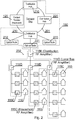
- Fig. 2 presents an example of a cable content distribution network.
- Such network is physically transmitting data between a content provider 120 and one or more receivers 113.
- One or more network distribution hubs 210, 220, 230 are typically present in order to aggregate subgroups of network nodes 231, 232, 233 and operate as local content distribution means.
- Local nodes, such as optical nodes 231, 232, 233 aggregate subgroups of households 110 and their respective receivers 113.
- 115E may be a Distribution RF amplifier while 115D may be a Local Bus RF amplifier and 115C may be a household amplifier.
- the Line RF amplifier 115D affects a signal for a single household 110 while the Bus RF amplifier 115E may affect signal transmitted to a plurality of households 110.
- Fig. 3 shows a signal reception adjustment means applicable in a satellite system.
- a satellite antenna 111 must be positioned in a correct manner in order to receive a proper signal from a satellite 160.
- the process of positioning said antenna is referred to as Satellite Antenna Alignment aimed at finding a correct pointing direction 301 and angle X1 with respect to a horizontal axis and angle X2 with respect to cardinal directions.
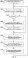
- Fig. 4 shows a method according to the present invention.
- the aim of the method is to improve testing and calibrating of an audio video signal be it an analog television signal, a digital terrestrial, cable or satellite television signal or the like.
- the method aims at verifying signal quality (and or strength) as evaluated by the receiver 113.
- the receiver 113 is in communication with a mobile device configured to receive parameters of the audio/video signals received by the receiver 113. Therefore, a single technician is able to configure the best possible signal reception parameters being physically away from the receiver 113.
- a mobile device At step 401 there is wirelessly connected a mobile device to an audio/video signal receiver 113.
- the wireless connection is preferred (e.g. Wi-Fi, UMTS, LTE or the like) but in certain embodiments a wired connection may be implemented.
- the mobile device receives signal parameters of a currently received signal (received by the receiver 113).
- the receiver 113 transmits such signal parameters to the mobile device.
- step 404 the mobile device receives audio/video channels list from the audio/video signal receiver 113. This is of course optionally possible if a proper audio/video signal has been previously received, wherein typically such signal also comprises a channels list. In case a proper signal has not yet been received, steps 404 and 405 will have to be skipped and executed after such proper signal has been received by the receiver 113.
- the mobile device receives audio/video signal from the receiver 113.
- the audio/video signal from the STB 113 is what will normally be output by the receiver 113 for example to a TV set 114.
- Such audio/video signal may have a different form than received by said receiver 113 i.e. have different format or be reduced in terms of resolution but shall still give the technician a good overview of what is currently received by said receiver 113.
- the mobile device displays, preferably simultaneously, said audio/video and signal parameters received from the receiver 113. In case video is not available, it will obviously not be presented.
- a technician may execute either manually or automatically (that is remotely using the mobile device), different adjustments of the aforementioned signal reception adjustment means 115A-E.
- Such signal reception adjustment means may be adjusted by means of the receiver 113 (for example by instructing DiSEqC (Digital Satellite Equipment Control) compatible dish antenna rotor to adjust) or directly by respective devices responsible for associated signal reception adjustment means.
- DiSEqC Digital Satellite Equipment Control
- the receiver 113 may provide (preferably at its connection at step 401) the mobile device with a list of associated signal reception adjustment means wherein such means may be identified for example with an IP address and/or supported configuration options. Therefore, at step 407, the mobile device may remotely execute adjustment of signal reception adjustment means associated with the receiver 113.
- the mobile device may optionally receive (from a user) a request to change channel or signal source by the receiver.
- the mobile device may remotely control the receiver 113 as a user would normally do using a dedicated remote control unit.
- commands may be sent from the mobile device 502 to the receiver 113 in order to execute at least a channel change and preferably all actions a dedicated remote control unit could execute.
- the mobile device returns to step 402 where the mobile device receives updated signal parameters and respective audio/video signal from the receiver 113 and presents these data to said technician.
- the mobile device preferably comprises a display screen.
- Fig. 5 presents an overview of the system wherein a technician 501 has a mobile device 502 communicating with a receiver 113 and a signal reception adjustment means 115A.
- a satellite antenna 111 may be installed on a roof of further away from the household 110 as shown in broken lines.
- Fig. 6 depicts modules of a mobile device 502.
- the mobile device 502 comprises an external interface module 630 responsible for bidirectional communication 603 with the receiver 113 and any external signal reception adjustment means (e.g. Wi-Fi, UMTS, LTE or the like).
- Other typical modules include a memory 640 for storing data (including software, configuration and the like) as well as software executed by a controller 610, a clock module 660 configured to provide clock reference for other modules of the system, and a media player 650 configured to process audio/video data 603 received by means of the external interface module 630.
- a display module 670 configured to display user interface and audio/video signal to a user.
- a suitable bidirectional data bus 601 may be employed in order to facilitate communication between modules and the controller 610.
- the controller 610 comprises a manager of signal reception adjustment means 611. This module is configured to control signal reception adjustment means based on information received at steps 401, 407. Further, the controller 610 may comprise a manager of remote control 612 configured to facilitate remote control the receiver 113.
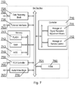
- Fig. 7 shows modules of an audio/video receiver 113.
- the audio/video receiver 113 comprises an external interface module 730 responsible for bidirectional communication 703 with the mobile device 502 and any external signal reception adjustment means (e.g. using wireless interface e.g. Wi-Fi, UMTS, LTE or the like).
- any external signal reception adjustment means e.g. using wireless interface e.g. Wi-Fi, UMTS, LTE or the like.
- Typical modules include a memory 740 (which may comprise different kinds of memory such as flash 741 and/or RAM 742 and/or HDD 743) for storing data (including software, configuration and the like) as well as software executed by a controller 710, a clock module 760 configured to provide clock reference for other modules of the system, and an audio/video block 770 configured to process audio/video data, received via the data receiving block 720, and output a video signal 707 by means of a video output interface.
- a memory 740 which may comprise different kinds of memory such as flash 741 and/or RAM 742 and/or HDD 743
- data including software, configuration and the like
- an audio/video block 770 configured to process audio/video data, received via the data receiving block 720, and output a video signal 707 by means of a video output interface.
- the receiver 113 comprises a remote control unit controller 750 configured to receive commands 705 from a remote control unit (typically using an infrared communication).
- the controller 710 comprises a manager of signal reception adjustment means 711. This module is configured to control signal reception adjustment means based on information received from the mobile device 502. Further, the controller 710 may comprise a manager of remote control 712 configured to facilitate remote control the receiver 113 by the mobile device 502.
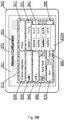
- FIGs. 8A-E show examples of a graphical user interface of the mobile device.
- a GUI shown in Fig. 8A presents an antenna configuration 802 on a mobile device 502.
- An antenna in this example comprises LNB 1 830 and LNB 2 840 that are to be fixed on selected satellites 831, 841.
- These parameters may only be communicated from the receiver 113 to the mobile device 502 and optionally may be modified by the mobile device 502 by communication between the manager of remote control 612 (of the mobile device) and the manager of remote control 712 (of the receiver).
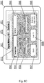
- Fig. 8B presents exemplary selection of satellites for an LNB while Fig. 8C presents information on a particular transponder of a selected satellite wherein said transponder may be selected as shown in Fig. 8E .
- this screen signal parameters are presented 854, 855, 856.
- a user may access adjustment means such as the position adjustment device 115A by selecting an option 'Antenna Alignment' 859.
- a user may view live signal by selecting option 858.
- Fig. 8D depicts remote configuration of the position adjustment device 115A by the mobile device 502. Said remote configuration may be executed directly or via the receiver 113. A user may use controls 859A-D to adjust antenna positioning while monitoring signal parameters 854, 855, 856.
- the aforementioned method for determining parameters of an audio/video signal, or parts thereof may be performed and/or controlled by one or more computer programs.
- Such computer programs are typically executed by utilizing the computing resources of the device.
- the computer programs can be stored in a non-volatile memory, for example a flash memory or in a volatile memory, for example RAM and are executed by the processing unit.
- These memories are exemplary recording media for storing computer programs comprising computer-executable instructions performing all the steps of the computer-implemented method according the technical concept presented herein.
Landscapes
- Physics & Mathematics (AREA)
- Astronomy & Astrophysics (AREA)
- General Physics & Mathematics (AREA)
- Engineering & Computer Science (AREA)
- Signal Processing (AREA)
- Two-Way Televisions, Distribution Of Moving Picture Or The Like (AREA)
Abstract
Method for determining parameters of an audio/video signal, received by an audio/video signal receiver (113), the method being characterized that it comprises the step of: wirelessly connecting (401) a mobile device (502) to the audio/video signal receiver (113); receiving (402) by the mobile device (502), signal parameters of a currently received signal, by the audio/video signal receiver (113); displaying 406, by the mobile device (502), said signal parameters; adjusting (407), by the mobile device (502) a signal reception adjustment means (115A-E) associated with the audio/video signal receiver (113) and; returning to step (402) in order to receive, from the audio/video signal receiver (113), updated signal parameters by the mobile device (502).
Description
- The present invention relates to determining parameters, such as quality, of an audio/video signal such as satellite, cable, terrestrial.
- One of most common measures of signal quality is a number of bit errors, which is the number of received bits of a data stream, over a communication channel, that have been altered due to noise, interference, distortion or bit synchronization errors (source: Wikipedia).
- The bit error rate or bit error ratio (BER) is the number of bit errors divided by the total number of transferred bits during a studied time interval. BER is a unitless performance measure, often expressed as a percentage.
- Other techniques of measuring signal quality are packet error rate or Signal-to-noise ratio (often abbreviated as SNR or S/N) or a combination of any of the aforementioned techniques.
- In addition to signal quality, signal strength may be monitored in such systems.
- The technical concept presented herein relates to a method that finds its application preferably in a satellite antenna installation.
- Currently, almost all of receivers of satellite signal, such as set-top box (STB), are equipped with satellite signal level and quality indicators. Such indicators can be displayed on a display screen or on STB's front panel LED/LCD displays.
- When an installer, of a satellite signal reception system, is to use the known indicator for the signal adjustments (e.g. aligning sat-tv dish), it usually requires another person, who passes the information to the installer on the roof about its exact reading value. It would be advantageous if the installer had a direct access to the reading information.
- Prior art discloses satellite signal meters that assist with aligning a satellite-TV dish without having to take the receiver outside. Such satellite signal meters help in optimizing dish alignment. In order to use such satellite signal meter one must disconnect the coaxial cable running from the receiver to a low-noise block LNB (typically at the LNB's end) and then connect the satellite signal meter to the LNB using a short coaxial cable. The receiver may then also be connected to the signal meter. The signal meter may then also be connected between receiver and the LNB.
- Prior art publication
US 6937188 B1 , entitled "Satellite antenna installation tool", discloses a portable device for assessing the degree of alignment between antenna and a satellite. In one embodiment, the device includes a portable housing that includes components for producing an audio and/or visual indication of the antenna's alignment with the satellite. The device may be self-contained and provide power to the antenna's frequency converter during the alignment process. The portable device is electronically coupled by a coaxial cable to a conventional RF input F-connector. - Drawback of this solution is that the measurement is executed on a different device than will ultimately use the signal. In practice there is a different tuner-demodulator arrangement.
- Another prior art publication
US 20060181455 A1 entitled "Method and device for accurately pointing a satellite earth station antenna", discloses an antenna pointing indicator system 60a may also include ahousing 140 that encloses particular components of antenna pointing indicator system 60a and/or to which particular components of antenna pointing indicator system 60a are mounted and forms a single physical device that includes the relevant components.FIG. 2 , of the aforementioned publication, shows two exemplary configurations ofhousing 140 to illustrate that signal meter 180 may or may not be enclosed along with signal amplifier 170,filter selector 160, and filters 150 in acommon housing 140. If signal meter 180 is not enclosed with thefilter assembly 150,filter selector 160 and optional amplifier 170 in a common housing; signal meter 180 may couple to output port 172 using, for example, a coaxial cable to connect the two components. In such an embodiment, signal meter 180 may also be configured to provide power to signal amplifier 170 through the coaxial cable or other element coupling the two components. In general, however, antenna pointing indicator system 60a may include ahousing 140 shaped and/or configured to include any appropriate combination of the individual elements of antenna pointing indicator system 60a. Alternatively, antenna pointing indicator system 60a may not include ahousing 140 of any type and the elements of antenna pointing indicator system 60a may all represent physically separate components. - In operation, in the illustrated embodiment, antenna pointing indicator system 60 receives an input signal at input port 162. Antenna pointing indicator system 60a may couple to user Earth
station antenna 20 and this input signal may comprise the total composite signal received by user Earthstation antenna 20 from satellite antennas 70, including background noise and interference. In a particular embodiment, input port 162 couples to user Earthstation antenna 20 through a coaxial cable. - Similarly, a drawback of this solution is that the measurement is executed on a different device than will ultimately use the signal. In practice there is a different tuner-demodulator arrangement.
- Another prior art publication
EP2830241 entitled "A method and system for determining parameters of a satellite signal", discloses a method for determining parameters of a satellite signal present in a coaxial cable, the method comprising the steps of aligning two capacitive coupling sensors in proximity to a length of the coaxial cable, wherein the distance between the capacitive coupling sensors is below 10 centimeters; receiving from the two capacitive coupling sensors a signal being a differential voltage in the coaxial cable between the locations of the capacitive coupling sensors wherein the voltage is relative to a voltage level in a coaxial cable; amplifying the differential voltage by a bandpass amplifier; detecting a valid DiSEqC command sequence being indicative of signal quality. - A drawback of this solution is that it is limited to DiSEqC systems only.
- It is therefore desirable to and improved method and system for determining parameters of an audio/video signal, in which the measurement is executed on the same device that will ultimately use the signal. Additionally, such device should be cost effective and provide information about the parameters of an audio/video signal in proximity to the installation location such as by a satellite antenna.
- The object of the present invention is a method for determining parameters of an audio/video signal, received by an audio/video signal receiver, the method being characterized that it comprises the step of: wirelessly connecting a mobile device to the audio/video signal receiver; receiving by the mobile device, signal parameters of a currently received signal, by the audio/video signal receiver; displaying, by the mobile device, said signal parameters; adjusting, by the mobile device a signal reception adjustment means associated with the audio/video signal receiver and; returning to step in order to receive, from the audio/video signal receiver, updated signal parameters by the mobile device.
- Preferably, the method further comprises the steps of: receiving, by the mobile device an audio/video signal, from the receiver, corresponding to the currently received signal; and displaying said audio/video signal by the mobile device.
- Preferably, the method further comprises a step of receiving, by the mobile device a request to change channel or signal source by the receiver and transmitting that request to the receiver.
- Another object of the present invention is a computer program comprising program code means for performing all the steps of the computer-implemented method according to the present invention when said program is run on a computer.
- Another object of the present invention is a computer readable medium storing computer-executable instructions performing all the steps of the computer-implemented method according to the present invention when executed on a computer.
- Lastly, an object of the present invention is a mobile device for determining parameters of an audio/video signal, received by an audio/video signal receiver, the mobile device being characterized in that it comprises: a manager of signal reception adjustment means, configured to control signal reception adjustment means based on information provided by said audio/video signal receiver; a controller configured to execute all steps of the method according to the present invention.
- The present invention is shown herein by means of exemplary embodiments on a drawing, in which:
-
Fig. 1 presents a schematic diagram of audio/video data reception system; -
Fig. 2 presents an example of a cable content distribution network; -
Fig. 3 shows a signal reception adjustment means applicable in a satellite system; -
Fig. 4 shows a method according to the present invention; -
Fig. 5 presents an overview of the system; -
Fig. 6 depicts modules of a mobile device; -
Fig. 7 shows modules of an audio/video receiver; and -
Figs. 8A-E show examples of a graphical user interface of the mobile device. - Some portions of the detailed description which follows are presented in terms of data processing procedures, steps or other symbolic representations of operations on data bits that can be performed on computer memory. Therefore, a computer executes such logical steps thus requiring physical manipulations of physical quantities.
- Usually these quantities take the form of electrical or magnetic signals capable of being stored, transferred, combined, compared, and otherwise manipulated in a computer system. For reasons of common usage, these signals are referred to as bits, packets, messages, values, elements, symbols, characters, terms, numbers, or the like.
- Additionally, all of these and similar terms are to be associated with the appropriate physical quantities and are merely convenient labels applied to these quantities. Terms such as "processing" or "creating" or "transferring" or "executing" or "determining" or "detecting" or "obtaining" or "selecting" or "calculating" or "generating" or the like, refer to the action and processes of a computer system that manipulates and transforms data represented as physical (electronic) quantities within the computer's registers and memories into other data similarly represented as physical quantities within the memories or registers or other such information storage.
- A computer-readable (storage) medium, such as referred to herein, typically may be non-transitory and/or comprise a non-transitory device. In this context, a non-transitory storage medium may include a device that may be tangible, meaning that the device has a concrete physical form, although the device may change its physical state. Thus, for example, non-transitory refers to a device remaining tangible despite a change in state.
- As utilized herein, the term "example" means serving as a non-limiting example, instance, or illustration. As utilized herein, the terms "for example" and "e.g." introduce a list of one or more non-limiting examples, instances, or illustrations.
-
Fig. 1 presents a schematic diagram of audio/video data reception system. In this example, anSTB receiver 113, connected to aTV set 114, is configured to receive audio/video data from a plurality ofsources - A
satellite antenna 111 receives a signal from asatellite transmitter 160. Thesatellite antenna 111 comprises aposition adjustment device 115A, which may be operated manually or automatically by for example electric engine(s). - A coaxial cable is typically passed to the inside of a
household 110 where it is connected to anSTB 113, comprising a satellite tuner and demodulator. After processing the satellite signal, theSTB 113 passes its output signal to adisplay 114 connected to it. - Similarly, a terrestrial audio/video data stream may be received via a
terrestrial antenna 112 from a terrestrial head-end transmitter 140. Theterrestrial antenna 112 may comprise aposition adjustment device 115B, which may be operated manually or automatically by for example electric engine(s). - Further, a cable audio/video data stream may be received via a cable signal reception means from a cable head-
end transmitter 120. A cable network may be a DOCSIS network, DVB-C, IPTV network or the like. A suitablecontent distribution network 150 may comprise signal adjustment device(s) 115C (as will be shown inFig. 2 ), which may be operated remotely by operators and/or installers. - The
adjustment devices -
Fig. 2 presents an example of a cable content distribution network. Such network is physically transmitting data between acontent provider 120 and one ormore receivers 113. One or morenetwork distribution hubs network nodes optical nodes households 110 and theirrespective receivers 113. - On the cable content distribution path, from the
content provider 120 to anSTB 113, there may be present different signal reception adjustment means 115C, 115D, 115E. For example, 115E may be a Distribution RF amplifier while 115D may be a Local Bus RF amplifier and 115C may be a household amplifier. TheLine RF amplifier 115D affects a signal for asingle household 110 while theBus RF amplifier 115E may affect signal transmitted to a plurality ofhouseholds 110. - A difference lies in the signal level, at which the respective amplifiers operate in the signal delivery path.
-
Fig. 3 shows a signal reception adjustment means applicable in a satellite system. - A
satellite antenna 111 must be positioned in a correct manner in order to receive a proper signal from asatellite 160. Sometimes the process of positioning said antenna is referred to as Satellite Antenna Alignment aimed at finding acorrect pointing direction 301 and angle X1 with respect to a horizontal axis and angle X2 with respect to cardinal directions. -
Fig. 4 shows a method according to the present invention. The aim of the method is to improve testing and calibrating of an audio video signal be it an analog television signal, a digital terrestrial, cable or satellite television signal or the like. The method aims at verifying signal quality (and or strength) as evaluated by thereceiver 113. To this end, thereceiver 113 is in communication with a mobile device configured to receive parameters of the audio/video signals received by thereceiver 113. Therefore, a single technician is able to configure the best possible signal reception parameters being physically away from thereceiver 113. - At
step 401 there is wirelessly connected a mobile device to an audio/video signal receiver 113. The wireless connection is preferred (e.g. Wi-Fi, UMTS, LTE or the like) but in certain embodiments a wired connection may be implemented. Next, atstep 402, the mobile device receives signal parameters of a currently received signal (received by the receiver 113). Preferably, thereceiver 113 transmits such signal parameters to the mobile device. - In case a proper signal is received 403 by the
receiver 113, proper meaning that audio/video may be decoded and output, the process advances to step 404, otherwise to step 406. Subsequently, atstep 404, the mobile device receives audio/video channels list from the audio/video signal receiver 113. This is of course optionally possible if a proper audio/video signal has been previously received, wherein typically such signal also comprises a channels list. In case a proper signal has not yet been received,steps receiver 113. - Further, at
step 405, the mobile device receives audio/video signal from thereceiver 113. The audio/video signal from theSTB 113 is what will normally be output by thereceiver 113 for example to aTV set 114. Such audio/video signal may have a different form than received by saidreceiver 113 i.e. have different format or be reduced in terms of resolution but shall still give the technician a good overview of what is currently received by saidreceiver 113. - Next, at
step 406, the mobile device displays, preferably simultaneously, said audio/video and signal parameters received from thereceiver 113. In case video is not available, it will obviously not be presented. - At this point, a technician may execute either manually or automatically (that is remotely using the mobile device), different adjustments of the aforementioned signal reception adjustment means 115A-E. Such signal reception adjustment means may be adjusted by means of the receiver 113 (for example by instructing DiSEqC (Digital Satellite Equipment Control) compatible dish antenna rotor to adjust) or directly by respective devices responsible for associated signal reception adjustment means.
- The
receiver 113 may provide (preferably at its connection at step 401) the mobile device with a list of associated signal reception adjustment means wherein such means may be identified for example with an IP address and/or supported configuration options. Therefore, atstep 407, the mobile device may remotely execute adjustment of signal reception adjustment means associated with thereceiver 113. - When said adjustments have been executed, at
step 408, the mobile device may optionally receive (from a user) a request to change channel or signal source by the receiver. In more complex embodiments the mobile device may remotely control thereceiver 113 as a user would normally do using a dedicated remote control unit. Thus commands may be sent from themobile device 502 to thereceiver 113 in order to execute at least a channel change and preferably all actions a dedicated remote control unit could execute. - Lastly, the mobile device returns to step 402 where the mobile device receives updated signal parameters and respective audio/video signal from the
receiver 113 and presents these data to said technician. To this end, the mobile device preferably comprises a display screen. -
Fig. 5 presents an overview of the system wherein atechnician 501 has amobile device 502 communicating with areceiver 113 and a signal reception adjustment means 115A. Asatellite antenna 111 may be installed on a roof of further away from thehousehold 110 as shown in broken lines. -
Fig. 6 depicts modules of amobile device 502. Themobile device 502 comprises anexternal interface module 630 responsible forbidirectional communication 603 with thereceiver 113 and any external signal reception adjustment means (e.g. Wi-Fi, UMTS, LTE or the like). Other typical modules include amemory 640 for storing data (including software, configuration and the like) as well as software executed by acontroller 610, aclock module 660 configured to provide clock reference for other modules of the system, and amedia player 650 configured to process audio/video data 603 received by means of theexternal interface module 630. - Other, typical, but optional modules of the
mobile device 502 are adisplay module 670 configured to display user interface and audio/video signal to a user. - A suitable
bidirectional data bus 601 may be employed in order to facilitate communication between modules and thecontroller 610. - The
controller 610 comprises a manager of signal reception adjustment means 611. This module is configured to control signal reception adjustment means based on information received atsteps controller 610 may comprise a manager ofremote control 612 configured to facilitate remote control thereceiver 113. -
Fig. 7 shows modules of an audio/video receiver 113. The audio/video receiver 113 comprises anexternal interface module 730 responsible forbidirectional communication 703 with themobile device 502 and any external signal reception adjustment means (e.g. using wireless interface e.g. Wi-Fi, UMTS, LTE or the like). Other typical modules include a memory 740 (which may comprise different kinds of memory such asflash 741 and/orRAM 742 and/or HDD 743) for storing data (including software, configuration and the like) as well as software executed by acontroller 710, aclock module 760 configured to provide clock reference for other modules of the system, and an audio/video block 770 configured to process audio/video data, received via thedata receiving block 720, and output avideo signal 707 by means of a video output interface. - Further, the
receiver 113 comprises a remotecontrol unit controller 750 configured to receivecommands 705 from a remote control unit (typically using an infrared communication). - The
controller 710 comprises a manager of signal reception adjustment means 711. This module is configured to control signal reception adjustment means based on information received from themobile device 502. Further, thecontroller 710 may comprise a manager ofremote control 712 configured to facilitate remote control thereceiver 113 by themobile device 502. -
Figs. 8A-E show examples of a graphical user interface of the mobile device. A GUI shown inFig. 8A presents anantenna configuration 802 on amobile device 502. An antenna in this example comprisesLNB 1 830 and LNB 2 840 that are to be fixed on selectedsatellites receiver 113 to themobile device 502 and optionally may be modified by themobile device 502 by communication between the manager of remote control 612 (of the mobile device) and the manager of remote control 712 (of the receiver). -
Fig. 8B presents exemplary selection of satellites for an LNB whileFig. 8C presents information on a particular transponder of a selected satellite wherein said transponder may be selected as shown inFig. 8E . In this screen signal parameters are presented 854, 855, 856. When such parameters are insufficient, e.g. quality below 50%, a user may access adjustment means such as theposition adjustment device 115A by selecting an option 'Antenna Alignment' 859. As another option, a user may view live signal by selectingoption 858. -
Fig. 8D depicts remote configuration of theposition adjustment device 115A by themobile device 502. Said remote configuration may be executed directly or via thereceiver 113. A user may usecontrols 859A-D to adjust antenna positioning while monitoringsignal parameters - It can be easily recognized, by one skilled in the art, that the aforementioned method for determining parameters of an audio/video signal, or parts thereof, may be performed and/or controlled by one or more computer programs. Such computer programs are typically executed by utilizing the computing resources of the device. The computer programs can be stored in a non-volatile memory, for example a flash memory or in a volatile memory, for example RAM and are executed by the processing unit. These memories are exemplary recording media for storing computer programs comprising computer-executable instructions performing all the steps of the computer-implemented method according the technical concept presented herein.
- While the invention presented herein has been depicted, described, and has been defined with reference to particular preferred embodiments, such references and examples of implementation in the foregoing specification do not imply any limitation on the invention. It will, however, be evident that various modifications and changes may be made thereto without departing from the broader scope of the technical concept. The presented preferred embodiments are exemplary only, and are not exhaustive of the scope of the technical concept presented herein.
- Accordingly, the scope of protection is not limited to the preferred embodiments described in the specification, but is only limited by the claims that follow.
Claims (6)
- A method for determining parameters of an audio/video signal, received by an audio/video signal receiver (113), the method being characterized that it comprises the step of:• wirelessly connecting (401) a mobile device (502) to the audio/video signal receiver (113);• receiving (402) by the mobile device (502), signal parameters of a currently received signal, by the audio/video signal receiver (113);• displaying 406, by the mobile device (502), said signal parameters;• adjusting (407), by the mobile device (502) a signal reception adjustment means (115A-E) associated with the audio/video signal receiver (113) and;• returning to step (402) in order to receive, from the audio/video signal receiver (113), updated signal parameters by the mobile device (502).
- The method according to claim 1, characterized in that it further comprises the steps of:• receiving (405), by the mobile device (502) an audio/video signal, from the receiver (113), corresponding to the currently received signal; and• displaying (406) said audio/video signal by the mobile device (502).
- The method according to claim 2, characterized in that the method further comprises a step of receiving (408), by the mobile device (502) a request to change channel or signal source by the receiver (113) and transmitting that request to the receiver (113).
- A computer program comprising program code means for performing all the steps of the computer-implemented method according to claim 1 when said program is run on a computer.
- A computer readable medium storing computer-executable instructions performing all the steps of the computer-implemented method according to claim 1 when executed on a computer.
- A mobile device (502) for determining parameters of an audio/video signal, received by an audio/video signal receiver (113), the mobile device being characterized in that it comprises:• a manager of signal reception adjustment means (611), configured to control signal reception adjustment means (115A-E) based on information provided by said audio/video signal receiver (113);• a controller (610) configured to execute all steps of the method according to claim 1.
Priority Applications (1)
| Application Number | Priority Date | Filing Date | Title |
|---|---|---|---|
| EP17152766.6A EP3352391A1 (en) | 2017-01-24 | 2017-01-24 | Method and system for determining parameters of an audio/video signal |
Applications Claiming Priority (1)
| Application Number | Priority Date | Filing Date | Title |
|---|---|---|---|
| EP17152766.6A EP3352391A1 (en) | 2017-01-24 | 2017-01-24 | Method and system for determining parameters of an audio/video signal |
Publications (1)
| Publication Number | Publication Date |
|---|---|
| EP3352391A1 true EP3352391A1 (en) | 2018-07-25 |
Family
ID=57890682
Family Applications (1)
| Application Number | Title | Priority Date | Filing Date |
|---|---|---|---|
| EP17152766.6A Withdrawn EP3352391A1 (en) | 2017-01-24 | 2017-01-24 | Method and system for determining parameters of an audio/video signal |
Country Status (1)
| Country | Link |
|---|---|
| EP (1) | EP3352391A1 (en) |
Citations (6)
| Publication number | Priority date | Publication date | Assignee | Title |
|---|---|---|---|---|
| US6937188B1 (en) | 2001-11-13 | 2005-08-30 | Bellsouth Intellectual Property Corporation | Satellite antenna installation tool |
| US20060181455A1 (en) | 2005-02-15 | 2006-08-17 | Wildblue Communications, Inc. | Method and device for accurately pointing a satellite earth station antenna |
| US20120127321A1 (en) * | 2010-11-18 | 2012-05-24 | Winegard Company | Wall plate digital television antenna signal meter and method |
| US20120155514A1 (en) * | 2010-12-17 | 2012-06-21 | Echostar Technologies L.L.C | Device for employing a portable communication device for antenna orientation optimization |
| EP2634937A1 (en) * | 2012-02-29 | 2013-09-04 | Harman International Industries Ltd. | Audio mixing console and mobile control unit |
| EP2830241A1 (en) | 2013-07-23 | 2015-01-28 | Advanced Digital Broadcast S.A. | A method and system for determining parameters of a satellite signal |
-
2017
- 2017-01-24 EP EP17152766.6A patent/EP3352391A1/en not_active Withdrawn
Patent Citations (6)
| Publication number | Priority date | Publication date | Assignee | Title |
|---|---|---|---|---|
| US6937188B1 (en) | 2001-11-13 | 2005-08-30 | Bellsouth Intellectual Property Corporation | Satellite antenna installation tool |
| US20060181455A1 (en) | 2005-02-15 | 2006-08-17 | Wildblue Communications, Inc. | Method and device for accurately pointing a satellite earth station antenna |
| US20120127321A1 (en) * | 2010-11-18 | 2012-05-24 | Winegard Company | Wall plate digital television antenna signal meter and method |
| US20120155514A1 (en) * | 2010-12-17 | 2012-06-21 | Echostar Technologies L.L.C | Device for employing a portable communication device for antenna orientation optimization |
| EP2634937A1 (en) * | 2012-02-29 | 2013-09-04 | Harman International Industries Ltd. | Audio mixing console and mobile control unit |
| EP2830241A1 (en) | 2013-07-23 | 2015-01-28 | Advanced Digital Broadcast S.A. | A method and system for determining parameters of a satellite signal |
Similar Documents
| Publication | Publication Date | Title |
|---|---|---|
| US8284112B2 (en) | Antenna orientation determination | |
| US20150058909A1 (en) | Set-top Box with Technical Configuration and System and Method for Use of Same | |
| US11223823B2 (en) | Set-top box with self-monitoring and system and method for use of same | |
| CN101448179B (en) | Automatic digital television receiving terminal test system, method and test equipment | |
| EP3200447A1 (en) | Mobile satellite television reception system and reception method | |
| US8949076B2 (en) | Real time monitoring and control of communications networks and radio frequency distribution networks | |
| TW201427421A (en) | A fast blind scan method insensitive to adjacent channel interference | |
| US9451220B1 (en) | System and method for aligning a multi-satellite receiver antenna | |
| US20050235325A1 (en) | Automatic reporting of antenna installation | |
| US20210126723A1 (en) | Smart signal level meter for antenna installation | |
| JP4007944B2 (en) | Digital broadcast receiving apparatus and reception level display method | |
| US8855546B2 (en) | Satellite receiver, method for operating a satellite receiver, computer program and satellite system | |
| EP2955783A1 (en) | A method for the installation with an electronic device of an outdoor unit and electronic device for such an installation | |
| US9031496B2 (en) | Apparatus and method for communication satellite monitoring | |
| CN101651790A (en) | TV, and device and method for indicating TV signal intensity | |
| US20050283808A1 (en) | Method for automatically detecting an antenna system for satellite receivers | |
| KR102278686B1 (en) | Amplifiers inintegrated reception system and method for controlling the same | |
| EP2830241B1 (en) | A method and system for determining parameters of a satellite signal | |
| US11831934B2 (en) | Set-top box with self-monitoring and system and method for use of same | |
| US20200412462A1 (en) | Per-channel modulation error ratio (mer) calibration and determination on a multi channel receiver | |
| US12237911B2 (en) | Apparatus for receiving and transmitting data via a satellite using at least two polarisations | |
| WO2009004461A2 (en) | Enhanced device for testing and calibrating a television signal | |
| US12072360B2 (en) | Modular meter | |
| CN103905800A (en) | A Fast Blind Scan Method Insensitive to Adjacent Channel Interference | |
| KR102261160B1 (en) | Broadcast System for Apartment by usingRF Signals Monitoring |
Legal Events
| Date | Code | Title | Description |
|---|---|---|---|
| PUAI | Public reference made under article 153(3) epc to a published international application that has entered the european phase |
Free format text: ORIGINAL CODE: 0009012 |
|
| AK | Designated contracting states |
Kind code of ref document: A1 Designated state(s): AL AT BE BG CH CY CZ DE DK EE ES FI FR GB GR HR HU IE IS IT LI LT LU LV MC MK MT NL NO PL PT RO RS SE SI SK SM TR |
|
| AX | Request for extension of the european patent |
Extension state: BA ME |
|
| STAA | Information on the status of an ep patent application or granted ep patent |
Free format text: STATUS: THE APPLICATION IS DEEMED TO BE WITHDRAWN |
|
| 18D | Application deemed to be withdrawn |
Effective date: 20190126 |