EP3352368A1 - Angle grinder, power tool and braking method thereof - Google Patents
Angle grinder, power tool and braking method thereof Download PDFInfo
- Publication number
- EP3352368A1 EP3352368A1 EP17203426.6A EP17203426A EP3352368A1 EP 3352368 A1 EP3352368 A1 EP 3352368A1 EP 17203426 A EP17203426 A EP 17203426A EP 3352368 A1 EP3352368 A1 EP 3352368A1
- Authority
- EP
- European Patent Office
- Prior art keywords
- output shaft
- rotor
- brake circuit
- windings
- motor
- Prior art date
- Legal status (The legal status is an assumption and is not a legal conclusion. Google has not performed a legal analysis and makes no representation as to the accuracy of the status listed.)
- Granted
Links
Images


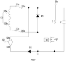


Classifications
-
- B—PERFORMING OPERATIONS; TRANSPORTING
- B24—GRINDING; POLISHING
- B24B—MACHINES, DEVICES, OR PROCESSES FOR GRINDING OR POLISHING; DRESSING OR CONDITIONING OF ABRADING SURFACES; FEEDING OF GRINDING, POLISHING, OR LAPPING AGENTS
- B24B23/00—Portable grinding machines, e.g. hand-guided; Accessories therefor
- B24B23/02—Portable grinding machines, e.g. hand-guided; Accessories therefor with rotating grinding tools; Accessories therefor
- B24B23/022—Spindle-locking devices, e.g. for mounting or removing the tool
-
- B—PERFORMING OPERATIONS; TRANSPORTING
- B23—MACHINE TOOLS; METAL-WORKING NOT OTHERWISE PROVIDED FOR
- B23Q—DETAILS, COMPONENTS, OR ACCESSORIES FOR MACHINE TOOLS, e.g. ARRANGEMENTS FOR COPYING OR CONTROLLING; MACHINE TOOLS IN GENERAL CHARACTERISED BY THE CONSTRUCTION OF PARTICULAR DETAILS OR COMPONENTS; COMBINATIONS OR ASSOCIATIONS OF METAL-WORKING MACHINES, NOT DIRECTED TO A PARTICULAR RESULT
- B23Q11/00—Accessories fitted to machine tools for keeping tools or parts of the machine in good working condition or for cooling work; Safety devices specially combined with or arranged in, or specially adapted for use in connection with, machine tools
- B23Q11/0078—Safety devices protecting the operator, e.g. against accident or noise
- B23Q11/0092—Safety devices protecting the operator, e.g. against accident or noise actuating braking or stopping means
-
- B—PERFORMING OPERATIONS; TRANSPORTING
- B24—GRINDING; POLISHING
- B24B—MACHINES, DEVICES, OR PROCESSES FOR GRINDING OR POLISHING; DRESSING OR CONDITIONING OF ABRADING SURFACES; FEEDING OF GRINDING, POLISHING, OR LAPPING AGENTS
- B24B23/00—Portable grinding machines, e.g. hand-guided; Accessories therefor
- B24B23/02—Portable grinding machines, e.g. hand-guided; Accessories therefor with rotating grinding tools; Accessories therefor
- B24B23/028—Angle tools
-
- B—PERFORMING OPERATIONS; TRANSPORTING
- B24—GRINDING; POLISHING
- B24B—MACHINES, DEVICES, OR PROCESSES FOR GRINDING OR POLISHING; DRESSING OR CONDITIONING OF ABRADING SURFACES; FEEDING OF GRINDING, POLISHING, OR LAPPING AGENTS
- B24B27/00—Other grinding machines or devices
- B24B27/06—Grinders for cutting-off
- B24B27/08—Grinders for cutting-off being portable
-
- B—PERFORMING OPERATIONS; TRANSPORTING
- B24—GRINDING; POLISHING
- B24B—MACHINES, DEVICES, OR PROCESSES FOR GRINDING OR POLISHING; DRESSING OR CONDITIONING OF ABRADING SURFACES; FEEDING OF GRINDING, POLISHING, OR LAPPING AGENTS
- B24B47/00—Drives or gearings; Equipment therefor
- B24B47/10—Drives or gearings; Equipment therefor for rotating or reciprocating working-spindles carrying grinding wheels or workpieces
- B24B47/12—Drives or gearings; Equipment therefor for rotating or reciprocating working-spindles carrying grinding wheels or workpieces by mechanical gearing or electric power
-
- H—ELECTRICITY
- H02—GENERATION; CONVERSION OR DISTRIBUTION OF ELECTRIC POWER
- H02P—CONTROL OR REGULATION OF ELECTRIC MOTORS, ELECTRIC GENERATORS OR DYNAMO-ELECTRIC CONVERTERS; CONTROLLING TRANSFORMERS, REACTORS OR CHOKE COILS
- H02P3/00—Arrangements for stopping or slowing electric motors, generators, or dynamo-electric converters
- H02P3/02—Details of stopping control
-
- H—ELECTRICITY
- H02—GENERATION; CONVERSION OR DISTRIBUTION OF ELECTRIC POWER
- H02P—CONTROL OR REGULATION OF ELECTRIC MOTORS, ELECTRIC GENERATORS OR DYNAMO-ELECTRIC CONVERTERS; CONTROLLING TRANSFORMERS, REACTORS OR CHOKE COILS
- H02P3/00—Arrangements for stopping or slowing electric motors, generators, or dynamo-electric converters
- H02P3/06—Arrangements for stopping or slowing electric motors, generators, or dynamo-electric converters for stopping or slowing an individual dynamo-electric motor or dynamo-electric converter
- H02P3/08—Arrangements for stopping or slowing electric motors, generators, or dynamo-electric converters for stopping or slowing an individual dynamo-electric motor or dynamo-electric converter for stopping or slowing a DC motor
- H02P3/16—Arrangements for stopping or slowing electric motors, generators, or dynamo-electric converters for stopping or slowing an individual dynamo-electric motor or dynamo-electric converter for stopping or slowing a DC motor by combined electrical and mechanical braking
-
- H—ELECTRICITY
- H02—GENERATION; CONVERSION OR DISTRIBUTION OF ELECTRIC POWER
- H02P—CONTROL OR REGULATION OF ELECTRIC MOTORS, ELECTRIC GENERATORS OR DYNAMO-ELECTRIC CONVERTERS; CONTROLLING TRANSFORMERS, REACTORS OR CHOKE COILS
- H02P3/00—Arrangements for stopping or slowing electric motors, generators, or dynamo-electric converters
- H02P3/06—Arrangements for stopping or slowing electric motors, generators, or dynamo-electric converters for stopping or slowing an individual dynamo-electric motor or dynamo-electric converter
- H02P3/18—Arrangements for stopping or slowing electric motors, generators, or dynamo-electric converters for stopping or slowing an individual dynamo-electric motor or dynamo-electric converter for stopping or slowing an AC motor
- H02P3/20—Arrangements for stopping or slowing electric motors, generators, or dynamo-electric converters for stopping or slowing an individual dynamo-electric motor or dynamo-electric converter for stopping or slowing an AC motor by reversal of phase sequence of connections to the motor
-
- H—ELECTRICITY
- H02—GENERATION; CONVERSION OR DISTRIBUTION OF ELECTRIC POWER
- H02P—CONTROL OR REGULATION OF ELECTRIC MOTORS, ELECTRIC GENERATORS OR DYNAMO-ELECTRIC CONVERTERS; CONTROLLING TRANSFORMERS, REACTORS OR CHOKE COILS
- H02P3/00—Arrangements for stopping or slowing electric motors, generators, or dynamo-electric converters
- H02P3/06—Arrangements for stopping or slowing electric motors, generators, or dynamo-electric converters for stopping or slowing an individual dynamo-electric motor or dynamo-electric converter
- H02P3/18—Arrangements for stopping or slowing electric motors, generators, or dynamo-electric converters for stopping or slowing an individual dynamo-electric motor or dynamo-electric converter for stopping or slowing an AC motor
- H02P3/22—Arrangements for stopping or slowing electric motors, generators, or dynamo-electric converters for stopping or slowing an individual dynamo-electric motor or dynamo-electric converter for stopping or slowing an AC motor by short-circuit or resistive braking
Definitions
- an angle grinder in one aspect of the disclosure, includes a motor including a rotor and windings, a power supply for supplying power to the motor, a main switch for turning on/off an electrical connection between the windings of the motor and the power supply, an output shaft driven by the rotor to rotate, a rotor brake circuit for slowing down the rotor of the motor when the windings are short circuited or reverse connected, an output shaft brake circuit for producing a magnetic field to slow down the output shaft and a controller for detecting whether the rotor brake circuit short circuits or reverse connects the windings. When the windings are short circuited or reverse connected for a time which reaches a preset value, the output shaft brake circuit produces the magnetic field to slow down the output shaft.
- a power tool in another aspect of the disclosure, includes a motor including a rotor and windings, an output shaft driven by the rotor to rotate, a rotor brake circuit for short circuiting or reverse connecting the winds so as to slow down the rotor, an output shaft brake circuit for producing a magnetic field to slow down the output shaft and a controller for detecting whether the rotor brake circuit short circuits or reverse connects with the windings.
- the output shaft brake circuit produces the magnetic field to slow down the output shaft.
- the magnetic element 134 responds the magnetic field produced by the output shaft brake circuit 40 and applies force on the friction element 131 to make the friction element 131 and the flange 124 separate when the connection of the motor 12 and the power supply 20 is turned on. When the connection of the motor 12 and the power supply 20 is turned off, the magnetic element 134 applies a force on the friction element 131 to make the friction element 131 and the flange 124 contact. So, the output shaft is stopped rapidly.
- the controller 50 can collect the current flowing through the windings 123 to determine whether the windings 123 are short circuited or reverse connected.
Landscapes
- Engineering & Computer Science (AREA)
- Mechanical Engineering (AREA)
- Power Engineering (AREA)
- Stopping Of Electric Motors (AREA)
Abstract
Description
- This application claims the benefit of Chinese Patent Application No.
CN 201611061012.0, filed on November 25, 2016 - The present disclosure relates generally to power tools and, more particularly, to a power tool being able to brake a motor.
- Power tools include a motor for driving a working attachment to perform the function of a tool.
- Angle grinders are a kind of hand-held power tools. A grinding disc is acted as the working attachment of the angle grinder, which is used to cut or grind a workpiece. When a user turns off or releases a switch, the grinding disc is expected to stop rapidly to prevent contact between the moving grinding disc and an object.
- The statements in this section merely provide background information related to the present disclosure and may not constitute prior art.
- In one aspect of the disclosure, an angle grinder is provided. The angle grinder includes a motor including a rotor and windings, a power supply for supplying power to the motor, a main switch for turning on/off an electrical connection between the windings of the motor and the power supply, an output shaft driven by the rotor to rotate, a rotor brake circuit for slowing down the rotor of the motor when the windings are short circuited or reverse connected, an output shaft brake circuit for producing a magnetic field to slow down the output shaft and a controller for detecting whether the rotor brake circuit short circuits or reverse connects the windings. When the windings are short circuited or reverse connected for a time which reaches a preset value, the output shaft brake circuit produces the magnetic field to slow down the output shaft.
- In another aspect of the disclosure, a power tool is provided. The power tool includes a motor including a rotor and windings, an output shaft driven by the rotor to rotate, a rotor brake circuit for short circuiting or reverse connecting the winds so as to slow down the rotor, an output shaft brake circuit for producing a magnetic field to slow down the output shaft and a controller for detecting whether the rotor brake circuit short circuits or reverse connects with the windings. When the windings are in a short circuit state or a reverse connection state for a time which reaches a preset value, the output shaft brake circuit produces the magnetic field to slow down the output shaft.
- In another aspect of the disclosure, a method for braking a motor of a power tool is provided. The motor includes a rotor and windings. The power tool includes a rotor brake circuit and an output shaft brake circuit. The method includes detecting whether the rotor brake circuit short circuits or reverse connects with the windings and, when the windings are in a short circuit state or a reverse connection state for a time which reaches a preset value, the output shaft brake circuit produces a magnetic field to slow down an output shaft
- Further areas of applicability will become apparent from the description provided herein. It should be understood that the description and specific examples are intended for purposes of illustration only and are not intended to limit the scope of the present disclosure.
-
-
FIG. 1 is a schematic view of an exemplary power tool. -
FIG. 2 an exploded view of the power tool inFIG. 1 . -
FIG. 3 is a circuit block diagram of the power tool inFIG. 1 . -
FIG. 4 is a circuit diagram of the power tool inFIG. 1 , wherein the motor is in a driving state. -
FIG. 5 is a circuit diagram of the power tool inFIG. 1 , wherein the motor is in a braking state. -
FIG. 6 is an equivalent circuit block diagram of a first loop circuit formed by the circuit diagram inFIG. 5 . -
FIG. 7 is an equivalent circuit block diagram of a second loop circuit formed by the circuit diagram inFIG. 5 . -
FIG. 8 is another circuit block diagram of the power tool inFIG. 1 . -
FIG. 9 is a flow diagram of a method for braking a motor of the power tool. - The drawings described herein are for illustrative purposes only of selected embodiments and not all possible implementations, and are not intended to limit the scope of the present disclosure. Corresponding reference numerals indicate corresponding parts throughout the several views of the drawings.
- The following description of the preferred embodiments is merely exemplary in nature and is in no way intended to limit the scope of the invention claimed, its application, or uses.
- Referring to
FIGS. 1-3 , apower tool 100 includes a grinding disc 110, amotor 12, an output shaft, amechanical braking device 13, apower supply 20, arotor brake circuit 30 and an outputshaft brake circuit 40. Specifically, thepower tool 100 is an angle grinder. - The grinding disc 110 is used to realize the function of grinding or cutting.
- The
power supply 20 is used to supply electric energy to themotor 12, which can be DC power or AC power. Specifically, the AC power is AC commercial power, and the DC power is supplied by a battery pack. When it is needed to convert the AC power to the DC power, atransformer 21 and a rectifying circuit 22 (as shown inFIG. 3 ) are disposed between thepower supply 20 and themotor 12. The AC power is reduced through thetransformer 21 which then outputs DC power through the rectifyingcircuit 22 to themotor 12. - The
motor 12 mainly includes arotor 121 andwindings 123. The power supply 20 supplies power to themotor 12. Thewindings 123 includescoils coils rotor 121 to rotate. Specifically, themotor 12 can be an AC motor or a DC motor, and a single-phase motor or a three-phrase motor. - The output shaft can be driven to rotate by the
rotor 121. An end of the output shaft is used to mount or fix the grinding disc 110. Therotor 121 rotates to drive the output shaft to rotate, and the output shaft drives the grinding disc 110 to rotate to grind or cut. It is noted that, a device which can be driven to rotate by therotor 121 can be considered as the output shaft of the present invention. As shown inFIG. 2 , aflange 124 is fastened on an end of amotor shaft 122 which is far from the grinding disc 110. Therotor 121 is able to drive theflange 124 to rotate. Both themotor shaft 122 and theflange 124 are the output shaft mentioned herein. However, in some power tools, the output shaft only includes themotor shaft 122 or includes themotor shaft 122 and other transmission device connected with themotor shaft 122. - A
main switch 31 is used to turn on/off the electrical connection of themotor 12 and thepower supply 20. Specifically, themain switch 31 is used to turn on/off the electrical connection of thewindings 122 of themotor 12 and thepower supply 20. In an exemplary tool, themain switch 31 is disposed at a position on the angle grinder which is easy for a user to operate. When the user activates themain switch 31, the electrical connection of themotor 12 and thepower supply 20 is turned on, and themotor 12 drives the grinding disc to grind or cut a workpiece. When the user releases themain switch 31, the electrical connection of themotor 12 and thepower supply 20 is turned off. Specifically, themain switch 31 is a single-pole double-throw switch or two linked single-pole double-throw switches. - When the user releases the
main switch 31, thegrinding disc 101 is preferably braked rapidly to prevent the movinggrinding disc 101 from accidentally contacting an object. - The
rotor brake circuit 30 is used to short-circuit or reverse connect thewindings 123 so as to slow down therotor 121 of themotor 12. Specifically, therotor brake circuit 30 is connected between thepower supply 20 and themotor 12. When the user releases themain switch 31, therotor brake circuit 30 starts working. Therotor brake circuit 30 short-circuits or reverse connects thewindings 123 so as to slow down therotor 121 of themotor 12, so that thegrinding disc 101 fastened on the output shaft is slowed down. - The output
shaft brake circuit 40 is used to produce a magnetic field for slowing down the output shaft. Themechanical braking device 13 responds to the magnetic field produced by the outputshaft brake circuit 40 and acts on the output shaft in a mechanical method so as to slow down the output shaft. So, the grindingdisc 101 is braked. - As shown in
FIG. 2 , alternatively, themechanical braking device 13 includes afriction element 131, a supportingelement 132, anelastic element 133 and amagnetic element 134. - The
friction element 131 rubs with theflange 124 to brake themotor shaft 122. Theflange 124 is formed with a braking surface for matching with thefriction element 131. The braking surface is substantially perpendicular to a rotation axis of themotor shaft 122. - The supporting
element 132 is used to fix thefriction element 131. Thefriction element 131 is made of wear-resistant material. The supportingelement 132 is made of metal material which can be attracted by themagnetic element 134 so as to separate thefriction element 131 and theflange 124. - The
elastic element 133 can apply a force on the supportingelement 132 and thefriction element 131 to make them separate. Specifically, theelastic element 133 is a spring. - The
magnetic element 134 responds the magnetic field produced by the outputshaft brake circuit 40 and applies force on thefriction element 131 to make thefriction element 131 and theflange 124 separate when the connection of themotor 12 and thepower supply 20 is turned on. When the connection of themotor 12 and thepower supply 20 is turned off, themagnetic element 134 applies a force on thefriction element 131 to make thefriction element 131 and theflange 124 contact. So, the output shaft is stopped rapidly. - A device which is able to respond the magnetic field produced by the output
shaft brake circuit 40 and brake the output shaft can be used as themechanical braking device 13 herein. - A
controller 50 is connected electrically with therotor brake circuit 30 and the outputshaft brake circuit 40. Thecontroller 50 can detect whether therotor brake circuit 30 short circuits or reverse connects thewindings 123. When thewindings 123 are short circuited or reverse connected for a time which reaches a preset value, thecontroller 50 outputs a control signal to the outputshaft brake circuit 40 so as to make the outputshaft brake circuit 40 produce the magnetic field for slowing down the output shaft. Specifically, the preset value is less than or equal to 3s. More specifically, the preset value is less than or equal to 2s. - Referring to
FIGS. 4-7 , a braking process of thepower tool 100 is illustrated. The main switch 312 is used to switch a driving state and a braking state of themotor 12. When the user activates the main switch 312, themotor 12 works normally. When the user releases the main switch 312, therotor brake circuit 30 starts working. Thecontroller 50 controls the outputshaft brake circuit 40 to work until themotor 12 stops rotating when the driving time of therotor brake circuit 30 reaches a preset value. - As shown in
FIG. 4 , a circuit diagram of thepower tool 100 is shown in which themotor 12 is in the driving state, and therotor brake circuit 30 and theoutput brake circuit 40 are not activated. - The
main switch 31 includes a first switch and a second switch. The first switch includes a first terminal 311 a, asecond terminal 311 b, and athird terminal 311 c. The first switch has a first state wherein the first terminal 311 a and thesecond terminal 311b are connected and a second state wherein the first terminal 311 a and thethird terminal 311 c are connected. The second switch includes a forth terminal 312a, afifth terminal 312b and asixth terminal 312c. The second switch has two states. In one of the two states, the forth terminal 312a and thefifth terminal 312b are connected, and in the other state, the forth terminal 312a and thesixth terminal 312c are connected. Thethird terminal 311 c is connected with thefifth terminal 312b. The first terminal 311 a is connected with thecoil 123a. Thesecond terminal 311b is connected with a connectingend 20a of thepower supply 20. The connectingend 20a is used to connect with one side of thepower supply 20. The other connectingend 20b of thepower supply 20 is connected with a connecting terminal 121 b of therotor 121. The first switch and the second switch are linked. That is, when the first switch is switched from the first state to the second state, the second switch switches from the state wherein the forth terminal 312a and thefifth terminal 312b are connected to the other state wherein the forth terminal 312a and thesixth terminal 312c are connected. When thefirst terminal 311a is connected with thethird terminal 311c and the forth terminal 312a is connected with thesixth terminal 312c, therotor brake circuit 30 is in the braking state and therotor 121 is short circuited or reverse connected, so that therotor 121 slows down. - When the user activates the
main switch 31, the first terminal 311 a is connected with thesecond terminal 311 b and the forth terminal 312a is connected with thefifth terminal 312b. Thepower supply 20, thecoils rotor 121 are connected in turn to constitute a closed circuit. Themotor 12 is in the driving state. - The circuit of the
power tool 100 further includes a tank circuit 60 connected with thepower supply 20. When themain switch 31 is turned on, the electric energy is stored in the tank circuit 60. When therotor brake circuit 30 works, the electric energy is released from the tank circuit 60. That is, when themotor 12 is in the driving sate, the electric energy is stored, and when themotor 12 is in the braking state, the electric energy is released. Specifically, the tank circuit 60 includes astorage element 61. An end of the tank circuit 60 is connected with thethird terminal 311 c, and the other end is connected with asecond semiconductor element 33. The current flowing through the tank circuit 60 only can flow from thethird terminal 311 c to the connectingend 20b of the power supply. Alternatively, thestorage element 61 is a capacitor C. - When the user releases the
main switch 31, the first terminal 311 a is connected with thethird terminal 311 c, and the forth terminal 312a is connected with thesixth terminal 312c. Therotor brake circuit 30 starts working. - Shown in
FIG. 5 is an example of themotor 12 in the braking state. Therotor brake circuit 30 includes themain switch 31, the connecting ends 20a, 20b of thepower supply 20, afirst semiconductor element 32, thesecond semiconductor element 33 and asemiconductor switch 34. Thesemiconductor switch 34 is connected electrically with thecontroller 50 to turn on/off therotor brake circuit 30. Thefirst semiconductor element 32 makes the current only flow from the sixth terminal 312c to thethird terminal 311c unidirectionally. Thesecond semiconductor element 33 makes the current only flow from the sixth terminal 312c to the connecting terminal 121 b of therotor 121 unidirectionally. - Specifically, the
first semiconductor element 32 is a free-wheeling diode D1. The anode of the diode D1 is connected with thesixth terminal 312c and the cathode of the diode D1 is connected with thethird terminal 311 c. Thesecond semiconductor element 33 is a diode D2. Thesemiconductor switch 34 is a field-effect transistor Q1. The drain electrode of the field-effect transistor Q1 is connected with thethird terminal 311c, the source electrode of the field-effect transistor Q1 is connected with the anode of the diode D1, and the grid electrode of the field-effect transistor Q1 is connected with thecontroller 50. - The output
shaft brake circuit 40 includes acoil 41 and abrake switch 42. Thebrake switch 42 is connected electrically with thecontroller 50 for turning on the electrical connection of the outputshaft brake circuit 40 and thepower supply 20. When thecoil 41 is powered on, it can produce a magnetic field for slowing down the output shaft. - Specifically, the
brake switch 42 is a field-effect transistor Q2. The high voltage terminal of thecoil 41 is connected with the positive electrode of thepower supply 20, and the low voltage terminal of thecoil 41 is connected with the drain electrode of the field-effect transistor Q2. The source electrode of the field-effect transistor Q2 is connected with the anode of the diode D2. The grid electrode of the field-effect transistor Q2 is connected with thecontroller 50. - Referring to
FIGS. 6-7 , an operating principle of therotor brake circuit 30 and the outputshaft brake circuit 40 is illustrated as follow. - As shown in
FIG. 6 , the first terminal 311 a is connected with thethird terminal 311 c, and the forth terminal 312a is connected with thesixth terminal 312c. The tank circuit 60 releases the electric energy. The field-effect transistor Q1 acting as thesemiconductor switch 34 is disconnected, and the diode D1 is turned on. The diode D1 and thewindings 123 constitute a first loop circuit. Thewindings 123 are short circuited to produce the magnetic field for stopping therotor 121 from rotating. So, therotor 121 is slowed down. Thecontroller 50 detects the short circuit of thewindings 123 and outputs a control signal to turn on the field-effect transistor Q2 acting as the outputshaft brake switch 42. As shown inFIG. 7 , the field-effect transistor Q1 acting as thesemiconductor switch 34 is turned on. The current flows through the field-effect transistor Q1, therotor 121 and thewindings 123 so as to constitute a second loop circuit. Thewindings 123 are reverse connected to produce the magnetic field for stopping the rotor from rotating. So, therotor 121 is slowed down. - The
controller 50 is connected electrically with therotor brake circuit 30 and the outputshaft brake circuit 40. When therotor brake circuit 30 works, thecontroller 50 determines whether thewindings 123 are short circuited or reverse connected. Specifically, thecontroller 50 collects the voltage of thethird terminal 311 c (the anode voltage of the capacitor C) and the voltage of thesixth terminal 312c. Thecontroller 50 determines whether thewindings 123 are short circuited or reverse connected according to the voltage detected. When the voltage of thethird terminal 311 c (the anode voltage of the capacitor C) and the voltage of thesixth terminal 312c are approximately equal, thewindings 123 are determined to be in the short circuit state. When the voltage of thethird terminal 311 c is less than the voltage of thesixth terminal 312c, thewindings 123 are determined to be in the reverse connection state. However, thecontroller 50 also can collect the current flowing through thewindings 123 to determine whether thewindings 123 are short circuited or reverse connected. - The
controller 50 detects whether thewindings 123 are short circuited or reverse connected and maintains thewindings 123 in the short circuit state or in the reverse connection state for the preset time value. Thecontroller 50 outputs the control signal to turn on the second semiconductor switch Q2. The outputshaft brake circuit 40 works. Thepower supply 20 supplies power to thecoil 41, and thecoil 41 produces the changing magnetic field to release themagnetic element 134. Themagnetic element 134 applies force on thefriction element 131 to make thefriction element 131 and theflange 124 contact. So, the output shaft is stopped rapidly. - As shown in
FIG. 8 , in another example thecontroller 50 can be replaced by a time-delay circuit 60. The time-delay circuit 60 at least includes a time-delay element which is able to maintain the windings in the short circuit state or in the reverse connection state for a preset time while detecting whether the windings are short circuited or reverse connected. And then the time-delay element turns on the rotor brake circuit to make the rotor brake circuit work. Specifically, the time-delay element is a capacitor. However, a combination of the time-delay circuit 60 and thecontroller 50 can be used. - The motor of the
power tool 100 is braked in a preset time through the rotor brake circuit. So, the speed of the motor is decreased rapidly. The output shaft is braked through the mechanical braking device activated by the output shaft brake circuit. Thus, the wear of the mechanical braking device is reduced while the braking efficiency of the motor is improved, and the service life is extended. - As shown in
FIG. 9 , a method for braking the motor of the power tool is shown, the motor includes the rotor and the windings. The power tool includes the rotor brake circuit and the output shaft brake circuit. The method includes detecting whether the windings are short circuited or reverse connected and, when the windings are in the short circuit state or in the reverse connection state for a time which reaches the preset value, the output shaft brake circuit produces the magnetic field for slowing down the output shaft. - As shown in
FIG. 9 , a method for braking the motor of the power tool is shown, the motor includes the rotor and the windings. The power tool includes the rotor brake circuit and the output shaft brake circuit. The method includes: - S1 detecting the rotor brake circuit (specifically, detecting the voltage of the
third terminal 311 c of the rotor brake circuit (the anode voltage of the capacitor C) and the voltage of the sixth terminal 312c); - S2 determining whether the windings are in the short circuit state or in the reverse connection state (When the voltage of the
third terminal 311 c (the anode voltage of the capacitor C) and the voltage of thesixth terminal 312c are approximately equal, thewindings 123 are determined to be in the short circuit state. When the voltage of thethird terminal 311 c is less than the voltage of thesixth terminal 312c, thewindings 123 are determined to be in the reverse connection state); - S3 if the windings are in the short circuit state or in the reverse connection state, the time t when the windings are in the short circuit state or in the reverse connection state is recorded, if not, going back to S1;
- S4 determining whether the time t is greater than or equal to the preset time to; and
- S5 if t≥t0, the output shaft brake circuit produces the magnetic field for slowing down the output shaft, if not, going back to S4.
- The above illustrates and describes basic principles, main features and advantages of the invention hereinafter claimed. Those skilled in the art should appreciate that the above examples do not limit the claimed invention in any form. Technical solutions obtained by equivalent substitution or equivalent variations all fall within the scope of the claimed invention.
Claims (10)
- An angle grinder, comprising:a motor comprising a rotor and windings;a power supply for supplying power to the motor;a main switch for turning on/off an electrical connection between the windings of the motor and the power supply;an output shaft driven by the rotor to rotate;a rotor brake circuit for slowing down the rotor of the motor when the windings are short circuited or reverse connected;an output shaft brake circuit for producing a magnetic field to slow down the output shaft; anda controller for detecting whether the rotor brake circuit short circuits or reverse connects the windings;wherein when the windings are short circuited or reverse connected for a time which reaches a preset value, the output shaft brake circuit produces the magnetic field to slow down the output shaft.
- The angle grinder of claim 1, wherein the preset value is less than or equal to 3s.
- The angle grinder of claim 1, further comprising an output shaft brake switch for turning on an electrical connection between the output shaft brake circuit and the power supply wherein the output shaft brake switch is connected electrically with the controller.
- The angle grinder of claim 3, wherein the output shaft brake switch is a field effect transistor.
- The angle grinder of claim 1, further comprises a mechanical braking device, the mechanical braking device comprising a magnetic element for responding to the output shaft brake circuit and producing a magnetic field to slow down the output shaft.
- The angle grinder of claim 1, wherein the rotor brake circuit comprises a semiconductor switch and the semiconductor switch is connected electrically with the controller for turning on/off the rotor brake circuit.
- The angle grinder of claim 1, further comprising a tank circuit wherein, when the main switch is powered on, electric energy is stored in the tank circuit and, when the rotor braking circuit is working, the electric energy is released from the tank circuit.
- The angle grinder of claim 1, wherein the main switch is a single-pole double-throw switch or two linked single-pole double-throw switches.
- A power tool, comprising:a motor comprising a rotor and windings;an output shaft driven by the rotor to rotate;a rotor brake circuit for short circuiting or reverse connecting the winds so as to slow down the rotor;an output shaft brake circuit for producing a magnetic field to slow down the output shaft; anda controller for detecting whether the rotor brake circuit short circuits or reverse connects the windings;wherein, when the windings are in a short circuit state or a reverse connection state for a time which reaches a preset value, the output shaft brake circuit produces the magnetic field to slow down the output shaft.
- A method for braking a motor of a power tool, wherein the motor comprises a rotor and windings and the power tool comprises a rotor brake circuit and an output shaft brake circuit, the method comprising:detecting whether the rotor brake circuit short circuits or reverse connects with the windings and;when the windings are in a short circuit state or a reverse connection state for a time which reaches a preset value, producing via use of the output shaft brake circuit a magnetic field to slow down an output shaft associated with the motor.
Applications Claiming Priority (1)
| Application Number | Priority Date | Filing Date | Title |
|---|---|---|---|
| CN201611061012.0A CN108098531B (en) | 2016-11-25 | 2016-11-25 | Angle grinder, electric tool and braking method thereof |
Publications (2)
| Publication Number | Publication Date |
|---|---|
| EP3352368A1 true EP3352368A1 (en) | 2018-07-25 |
| EP3352368B1 EP3352368B1 (en) | 2022-01-05 |
Family
ID=60543338
Family Applications (1)
| Application Number | Title | Priority Date | Filing Date |
|---|---|---|---|
| EP17203426.6A Active EP3352368B1 (en) | 2016-11-25 | 2017-11-24 | Angle grinder, power tool and braking method thereof |
Country Status (3)
| Country | Link |
|---|---|
| US (1) | US10478933B2 (en) |
| EP (1) | EP3352368B1 (en) |
| CN (1) | CN108098531B (en) |
Families Citing this family (6)
| Publication number | Priority date | Publication date | Assignee | Title |
|---|---|---|---|---|
| WO2018131293A1 (en) * | 2017-01-13 | 2018-07-19 | 株式会社 マキタ | Electrically powered tool |
| CN108512464B (en) * | 2017-02-24 | 2020-07-17 | 南京德朔实业有限公司 | Brake circuit and electric tool |
| USD891892S1 (en) * | 2018-06-14 | 2020-08-04 | Robert Bosch Gmbh | Angle grinder |
| WO2020107128A1 (en) * | 2018-11-30 | 2020-06-04 | Ats Automation Tooling Systems Inc. | System and method for electric motor control in a manufacturing environment |
| US12556113B2 (en) | 2021-02-10 | 2026-02-17 | Techtronic Cordless Gp | Device and method for motor braking |
| US20230381920A1 (en) * | 2022-05-25 | 2023-11-30 | Raytheon Technologies Corporation | Machine control for grinding machine |
Citations (3)
| Publication number | Priority date | Publication date | Assignee | Title |
|---|---|---|---|---|
| EP0578366A2 (en) * | 1992-06-05 | 1994-01-12 | Black & Decker Inc. | Controlled braking device for electric motors and in particular portable tools |
| EP1857229A1 (en) * | 2006-05-16 | 2007-11-21 | Abb Ab | A control system for an industrial robot |
| DE102010043184A1 (en) * | 2010-10-29 | 2012-05-03 | Robert Bosch Gmbh | Machine tool braking device |
Family Cites Families (25)
| Publication number | Priority date | Publication date | Assignee | Title |
|---|---|---|---|---|
| DE1210266B (en) * | 1958-12-31 | 1966-02-03 | Schuler L Ag | Disc friction clutch for presses |
| DE3844617A1 (en) * | 1988-08-26 | 1990-03-22 | Licentia Gmbh | Power tool with a combined device for braking to standstill and for clamping the tool |
| EP0358531B1 (en) * | 1988-09-09 | 1994-03-02 | Yamazaki Mazak Kabushiki Kaisha | Workpiece spindle control unit and control method |
| DE4307356A1 (en) * | 1993-03-09 | 1994-09-15 | Bosch Gmbh Robert | Series motor, especially universal motor, with a braking device |
| US5828195A (en) * | 1996-08-29 | 1998-10-27 | Universal Instruments Corporation | Method and apparatus for electronic braking of an electric motor having no permanent magnets |
| GB2380151B (en) * | 2001-07-20 | 2004-09-22 | Black & Decker Inc | Oscillating hand tool |
| DE10353302A1 (en) * | 2003-11-11 | 2005-06-09 | C. & E. Fein Gmbh | Electric tool and method for controlling a power tool |
| CN100339609C (en) * | 2004-05-31 | 2007-09-26 | 常州合力电器有限公司 | Electromagnetic brake for blade electric tool |
| JP2006123596A (en) * | 2004-10-26 | 2006-05-18 | Yazaki Corp | Motor control device |
| CN101208853A (en) * | 2005-03-23 | 2008-06-25 | 波峰实验室责任有限公司 | Motor and manufacturing method |
| CN201275751Y (en) * | 2005-10-12 | 2009-07-22 | 布莱克和戴克公司 | Universal control module |
| CN201349196Y (en) * | 2006-10-12 | 2009-11-18 | 布莱克和戴克公司 | Power tool and control module for same |
| US7654886B2 (en) * | 2007-07-16 | 2010-02-02 | Tse-Hua Chang | Pneumatic grinder |
| JP5203243B2 (en) * | 2009-02-03 | 2013-06-05 | 株式会社マキタ | Screw tightening tool |
| JP5447980B2 (en) * | 2010-07-16 | 2014-03-19 | 株式会社マキタ | Brake mechanism selection structure for electric tools |
| DE102010032335A1 (en) * | 2010-07-20 | 2012-01-26 | C. & E. Fein Gmbh | hand tool |
| DE102010043178A1 (en) * | 2010-10-29 | 2012-05-03 | Robert Bosch Gmbh | Machine tool braking device |
| JP5981219B2 (en) * | 2012-05-18 | 2016-08-31 | 株式会社マキタ | Braking device for three-phase brushless motor and electrical equipment |
| CN202617053U (en) * | 2012-06-05 | 2012-12-19 | 浙江北辰电机制造有限公司 | Brake system of electric tool |
| DE102013016216A1 (en) * | 2013-09-28 | 2015-04-02 | Andreas Stihl Ag & Co. Kg | "Method for braking an electric drive motor" |
| US9762153B2 (en) * | 2013-10-18 | 2017-09-12 | Black & Decker Inc. | Cycle-by-cycle current limit for power tools having a brushless motor |
| JP6155175B2 (en) * | 2013-11-18 | 2017-06-28 | 株式会社マキタ | Electric tool braking device |
| CN106329821B (en) * | 2015-06-26 | 2018-11-20 | 佛山市建准电子有限公司 | Motor system and the fan system for using the motor system |
| JP6847763B2 (en) * | 2017-05-18 | 2021-03-24 | 株式会社マキタ | Electric tool |
| DE102017124745A1 (en) * | 2017-10-23 | 2019-04-25 | C. & E. Fein Gmbh | Oscillation drive with adjustable oscillation angle |
-
2016
- 2016-11-25 CN CN201611061012.0A patent/CN108098531B/en active Active
-
2017
- 2017-11-22 US US15/820,646 patent/US10478933B2/en active Active
- 2017-11-24 EP EP17203426.6A patent/EP3352368B1/en active Active
Patent Citations (3)
| Publication number | Priority date | Publication date | Assignee | Title |
|---|---|---|---|---|
| EP0578366A2 (en) * | 1992-06-05 | 1994-01-12 | Black & Decker Inc. | Controlled braking device for electric motors and in particular portable tools |
| EP1857229A1 (en) * | 2006-05-16 | 2007-11-21 | Abb Ab | A control system for an industrial robot |
| DE102010043184A1 (en) * | 2010-10-29 | 2012-05-03 | Robert Bosch Gmbh | Machine tool braking device |
Also Published As
| Publication number | Publication date |
|---|---|
| CN108098531A (en) | 2018-06-01 |
| EP3352368B1 (en) | 2022-01-05 |
| CN108098531B (en) | 2021-08-27 |
| US20180147682A1 (en) | 2018-05-31 |
| US10478933B2 (en) | 2019-11-19 |
Similar Documents
| Publication | Publication Date | Title |
|---|---|---|
| EP3352368B1 (en) | Angle grinder, power tool and braking method thereof | |
| JP3207985U (en) | Motor drive system | |
| JP6414603B2 (en) | Electric tool | |
| RU2588959C2 (en) | Electric tool | |
| US11511387B2 (en) | Electric tool | |
| US9716448B2 (en) | Power tool and control circuit thereof | |
| JPWO2016098563A1 (en) | Electric tool | |
| JP2014091167A (en) | Electric power tool | |
| US20170288583A1 (en) | Power tool and motor drive system thereof | |
| US10892691B2 (en) | Control circuit and power tool | |
| RU2560092C2 (en) | Electrically operated machine | |
| US5708333A (en) | Series-wound motor with a braking element | |
| EP4501547A1 (en) | Power tool | |
| CN109866097B (en) | Electric tool and its starting method | |
| CN104617831A (en) | Driving device for single-phase series excitation commutator motor | |
| JP2018140447A (en) | Power tool | |
| CN2682793Y (en) | Electric mower | |
| JP2018051677A (en) | Working machine | |
| CN209207175U (en) | Circuit for controlling motor angle mill and ground for angle | |
| JP4474899B2 (en) | Power generator | |
| JP2005130651A (en) | Power supply device and wind power generator provided with the same | |
| CN108340250A (en) | It grinds at angle | |
| CN108394315A (en) | Intelligent electric motor car |
Legal Events
| Date | Code | Title | Description |
|---|---|---|---|
| PUAI | Public reference made under article 153(3) epc to a published international application that has entered the european phase |
Free format text: ORIGINAL CODE: 0009012 |
|
| STAA | Information on the status of an ep patent application or granted ep patent |
Free format text: STATUS: THE APPLICATION HAS BEEN PUBLISHED |
|
| AK | Designated contracting states |
Kind code of ref document: A1 Designated state(s): AL AT BE BG CH CY CZ DE DK EE ES FI FR GB GR HR HU IE IS IT LI LT LU LV MC MK MT NL NO PL PT RO RS SE SI SK SM TR |
|
| AX | Request for extension of the european patent |
Extension state: BA ME |
|
| STAA | Information on the status of an ep patent application or granted ep patent |
Free format text: STATUS: REQUEST FOR EXAMINATION WAS MADE |
|
| 17P | Request for examination filed |
Effective date: 20181204 |
|
| RBV | Designated contracting states (corrected) |
Designated state(s): AL AT BE BG CH CY CZ DE DK EE ES FI FR GB GR HR HU IE IS IT LI LT LU LV MC MK MT NL NO PL PT RO RS SE SI SK SM TR |
|
| GRAP | Despatch of communication of intention to grant a patent |
Free format text: ORIGINAL CODE: EPIDOSNIGR1 |
|
| STAA | Information on the status of an ep patent application or granted ep patent |
Free format text: STATUS: GRANT OF PATENT IS INTENDED |
|
| RIC1 | Information provided on ipc code assigned before grant |
Ipc: H02P 3/16 20060101ALI20211006BHEP Ipc: H02P 3/02 20060101AFI20211006BHEP |
|
| INTG | Intention to grant announced |
Effective date: 20211021 |
|
| GRAS | Grant fee paid |
Free format text: ORIGINAL CODE: EPIDOSNIGR3 |
|
| GRAA | (expected) grant |
Free format text: ORIGINAL CODE: 0009210 |
|
| STAA | Information on the status of an ep patent application or granted ep patent |
Free format text: STATUS: THE PATENT HAS BEEN GRANTED |
|
| AK | Designated contracting states |
Kind code of ref document: B1 Designated state(s): AL AT BE BG CH CY CZ DE DK EE ES FI FR GB GR HR HU IE IS IT LI LT LU LV MC MK MT NL NO PL PT RO RS SE SI SK SM TR |
|
| REG | Reference to a national code |
Ref country code: GB Ref legal event code: FG4D |
|
| REG | Reference to a national code |
Ref country code: CH Ref legal event code: EP |
|
| REG | Reference to a national code |
Ref country code: AT Ref legal event code: REF Ref document number: 1461485 Country of ref document: AT Kind code of ref document: T Effective date: 20220115 |
|
| REG | Reference to a national code |
Ref country code: DE Ref legal event code: R096 Ref document number: 602017051832 Country of ref document: DE |
|
| REG | Reference to a national code |
Ref country code: IE Ref legal event code: FG4D |
|
| REG | Reference to a national code |
Ref country code: LT Ref legal event code: MG9D |
|
| REG | Reference to a national code |
Ref country code: NL Ref legal event code: MP Effective date: 20220105 |
|
| REG | Reference to a national code |
Ref country code: AT Ref legal event code: MK05 Ref document number: 1461485 Country of ref document: AT Kind code of ref document: T Effective date: 20220105 |
|
| PG25 | Lapsed in a contracting state [announced via postgrant information from national office to epo] |
Ref country code: NL Free format text: LAPSE BECAUSE OF FAILURE TO SUBMIT A TRANSLATION OF THE DESCRIPTION OR TO PAY THE FEE WITHIN THE PRESCRIBED TIME-LIMIT Effective date: 20220105 |
|
| PG25 | Lapsed in a contracting state [announced via postgrant information from national office to epo] |
Ref country code: SE Free format text: LAPSE BECAUSE OF FAILURE TO SUBMIT A TRANSLATION OF THE DESCRIPTION OR TO PAY THE FEE WITHIN THE PRESCRIBED TIME-LIMIT Effective date: 20220105 Ref country code: RS Free format text: LAPSE BECAUSE OF FAILURE TO SUBMIT A TRANSLATION OF THE DESCRIPTION OR TO PAY THE FEE WITHIN THE PRESCRIBED TIME-LIMIT Effective date: 20220105 Ref country code: PT Free format text: LAPSE BECAUSE OF FAILURE TO SUBMIT A TRANSLATION OF THE DESCRIPTION OR TO PAY THE FEE WITHIN THE PRESCRIBED TIME-LIMIT Effective date: 20220505 Ref country code: NO Free format text: LAPSE BECAUSE OF FAILURE TO SUBMIT A TRANSLATION OF THE DESCRIPTION OR TO PAY THE FEE WITHIN THE PRESCRIBED TIME-LIMIT Effective date: 20220405 Ref country code: LT Free format text: LAPSE BECAUSE OF FAILURE TO SUBMIT A TRANSLATION OF THE DESCRIPTION OR TO PAY THE FEE WITHIN THE PRESCRIBED TIME-LIMIT Effective date: 20220105 Ref country code: HR Free format text: LAPSE BECAUSE OF FAILURE TO SUBMIT A TRANSLATION OF THE DESCRIPTION OR TO PAY THE FEE WITHIN THE PRESCRIBED TIME-LIMIT Effective date: 20220105 Ref country code: ES Free format text: LAPSE BECAUSE OF FAILURE TO SUBMIT A TRANSLATION OF THE DESCRIPTION OR TO PAY THE FEE WITHIN THE PRESCRIBED TIME-LIMIT Effective date: 20220105 Ref country code: BG Free format text: LAPSE BECAUSE OF FAILURE TO SUBMIT A TRANSLATION OF THE DESCRIPTION OR TO PAY THE FEE WITHIN THE PRESCRIBED TIME-LIMIT Effective date: 20220405 |
|
| PG25 | Lapsed in a contracting state [announced via postgrant information from national office to epo] |
Ref country code: PL Free format text: LAPSE BECAUSE OF FAILURE TO SUBMIT A TRANSLATION OF THE DESCRIPTION OR TO PAY THE FEE WITHIN THE PRESCRIBED TIME-LIMIT Effective date: 20220105 Ref country code: LV Free format text: LAPSE BECAUSE OF FAILURE TO SUBMIT A TRANSLATION OF THE DESCRIPTION OR TO PAY THE FEE WITHIN THE PRESCRIBED TIME-LIMIT Effective date: 20220105 Ref country code: GR Free format text: LAPSE BECAUSE OF FAILURE TO SUBMIT A TRANSLATION OF THE DESCRIPTION OR TO PAY THE FEE WITHIN THE PRESCRIBED TIME-LIMIT Effective date: 20220406 Ref country code: FI Free format text: LAPSE BECAUSE OF FAILURE TO SUBMIT A TRANSLATION OF THE DESCRIPTION OR TO PAY THE FEE WITHIN THE PRESCRIBED TIME-LIMIT Effective date: 20220105 Ref country code: AT Free format text: LAPSE BECAUSE OF FAILURE TO SUBMIT A TRANSLATION OF THE DESCRIPTION OR TO PAY THE FEE WITHIN THE PRESCRIBED TIME-LIMIT Effective date: 20220105 |
|
| PG25 | Lapsed in a contracting state [announced via postgrant information from national office to epo] |
Ref country code: IS Free format text: LAPSE BECAUSE OF FAILURE TO SUBMIT A TRANSLATION OF THE DESCRIPTION OR TO PAY THE FEE WITHIN THE PRESCRIBED TIME-LIMIT Effective date: 20220505 |
|
| REG | Reference to a national code |
Ref country code: DE Ref legal event code: R097 Ref document number: 602017051832 Country of ref document: DE |
|
| PG25 | Lapsed in a contracting state [announced via postgrant information from national office to epo] |
Ref country code: SM Free format text: LAPSE BECAUSE OF FAILURE TO SUBMIT A TRANSLATION OF THE DESCRIPTION OR TO PAY THE FEE WITHIN THE PRESCRIBED TIME-LIMIT Effective date: 20220105 Ref country code: SK Free format text: LAPSE BECAUSE OF FAILURE TO SUBMIT A TRANSLATION OF THE DESCRIPTION OR TO PAY THE FEE WITHIN THE PRESCRIBED TIME-LIMIT Effective date: 20220105 Ref country code: RO Free format text: LAPSE BECAUSE OF FAILURE TO SUBMIT A TRANSLATION OF THE DESCRIPTION OR TO PAY THE FEE WITHIN THE PRESCRIBED TIME-LIMIT Effective date: 20220105 Ref country code: EE Free format text: LAPSE BECAUSE OF FAILURE TO SUBMIT A TRANSLATION OF THE DESCRIPTION OR TO PAY THE FEE WITHIN THE PRESCRIBED TIME-LIMIT Effective date: 20220105 Ref country code: DK Free format text: LAPSE BECAUSE OF FAILURE TO SUBMIT A TRANSLATION OF THE DESCRIPTION OR TO PAY THE FEE WITHIN THE PRESCRIBED TIME-LIMIT Effective date: 20220105 Ref country code: CZ Free format text: LAPSE BECAUSE OF FAILURE TO SUBMIT A TRANSLATION OF THE DESCRIPTION OR TO PAY THE FEE WITHIN THE PRESCRIBED TIME-LIMIT Effective date: 20220105 |
|
| PLBE | No opposition filed within time limit |
Free format text: ORIGINAL CODE: 0009261 |
|
| STAA | Information on the status of an ep patent application or granted ep patent |
Free format text: STATUS: NO OPPOSITION FILED WITHIN TIME LIMIT |
|
| PG25 | Lapsed in a contracting state [announced via postgrant information from national office to epo] |
Ref country code: AL Free format text: LAPSE BECAUSE OF FAILURE TO SUBMIT A TRANSLATION OF THE DESCRIPTION OR TO PAY THE FEE WITHIN THE PRESCRIBED TIME-LIMIT Effective date: 20220105 |
|
| 26N | No opposition filed |
Effective date: 20221006 |
|
| PG25 | Lapsed in a contracting state [announced via postgrant information from national office to epo] |
Ref country code: SI Free format text: LAPSE BECAUSE OF FAILURE TO SUBMIT A TRANSLATION OF THE DESCRIPTION OR TO PAY THE FEE WITHIN THE PRESCRIBED TIME-LIMIT Effective date: 20220105 |
|
| PG25 | Lapsed in a contracting state [announced via postgrant information from national office to epo] |
Ref country code: MC Free format text: LAPSE BECAUSE OF FAILURE TO SUBMIT A TRANSLATION OF THE DESCRIPTION OR TO PAY THE FEE WITHIN THE PRESCRIBED TIME-LIMIT Effective date: 20220105 |
|
| REG | Reference to a national code |
Ref country code: CH Ref legal event code: PL |
|
| REG | Reference to a national code |
Ref country code: BE Ref legal event code: MM Effective date: 20221130 |
|
| PG25 | Lapsed in a contracting state [announced via postgrant information from national office to epo] |
Ref country code: LI Free format text: LAPSE BECAUSE OF NON-PAYMENT OF DUE FEES Effective date: 20221130 Ref country code: IT Free format text: LAPSE BECAUSE OF FAILURE TO SUBMIT A TRANSLATION OF THE DESCRIPTION OR TO PAY THE FEE WITHIN THE PRESCRIBED TIME-LIMIT Effective date: 20220105 Ref country code: CH Free format text: LAPSE BECAUSE OF NON-PAYMENT OF DUE FEES Effective date: 20221130 |
|
| PG25 | Lapsed in a contracting state [announced via postgrant information from national office to epo] |
Ref country code: LU Free format text: LAPSE BECAUSE OF NON-PAYMENT OF DUE FEES Effective date: 20221124 |
|
| PG25 | Lapsed in a contracting state [announced via postgrant information from national office to epo] |
Ref country code: IE Free format text: LAPSE BECAUSE OF NON-PAYMENT OF DUE FEES Effective date: 20221124 |
|
| PG25 | Lapsed in a contracting state [announced via postgrant information from national office to epo] |
Ref country code: BE Free format text: LAPSE BECAUSE OF NON-PAYMENT OF DUE FEES Effective date: 20221130 |
|
| PG25 | Lapsed in a contracting state [announced via postgrant information from national office to epo] |
Ref country code: HU Free format text: LAPSE BECAUSE OF FAILURE TO SUBMIT A TRANSLATION OF THE DESCRIPTION OR TO PAY THE FEE WITHIN THE PRESCRIBED TIME-LIMIT; INVALID AB INITIO Effective date: 20171124 |
|
| PG25 | Lapsed in a contracting state [announced via postgrant information from national office to epo] |
Ref country code: CY Free format text: LAPSE BECAUSE OF FAILURE TO SUBMIT A TRANSLATION OF THE DESCRIPTION OR TO PAY THE FEE WITHIN THE PRESCRIBED TIME-LIMIT Effective date: 20220105 |
|
| PG25 | Lapsed in a contracting state [announced via postgrant information from national office to epo] |
Ref country code: MK Free format text: LAPSE BECAUSE OF FAILURE TO SUBMIT A TRANSLATION OF THE DESCRIPTION OR TO PAY THE FEE WITHIN THE PRESCRIBED TIME-LIMIT Effective date: 20220105 |
|
| PG25 | Lapsed in a contracting state [announced via postgrant information from national office to epo] |
Ref country code: MT Free format text: LAPSE BECAUSE OF FAILURE TO SUBMIT A TRANSLATION OF THE DESCRIPTION OR TO PAY THE FEE WITHIN THE PRESCRIBED TIME-LIMIT Effective date: 20220105 |
|
| PG25 | Lapsed in a contracting state [announced via postgrant information from national office to epo] |
Ref country code: TR Free format text: LAPSE BECAUSE OF FAILURE TO SUBMIT A TRANSLATION OF THE DESCRIPTION OR TO PAY THE FEE WITHIN THE PRESCRIBED TIME-LIMIT Effective date: 20220105 |
|
| PGFP | Annual fee paid to national office [announced via postgrant information from national office to epo] |
Ref country code: DE Payment date: 20251028 Year of fee payment: 9 |
|
| PGFP | Annual fee paid to national office [announced via postgrant information from national office to epo] |
Ref country code: GB Payment date: 20251030 Year of fee payment: 9 |
|
| PGFP | Annual fee paid to national office [announced via postgrant information from national office to epo] |
Ref country code: FR Payment date: 20251117 Year of fee payment: 9 |