EP3352289B1 - Storage battery control device - Google Patents
Storage battery control device Download PDFInfo
- Publication number
- EP3352289B1 EP3352289B1 EP16844103.8A EP16844103A EP3352289B1 EP 3352289 B1 EP3352289 B1 EP 3352289B1 EP 16844103 A EP16844103 A EP 16844103A EP 3352289 B1 EP3352289 B1 EP 3352289B1
- Authority
- EP
- European Patent Office
- Prior art keywords
- battery
- limit value
- storage battery
- charge
- use state
- Prior art date
- Legal status (The legal status is an assumption and is not a legal conclusion. Google has not performed a legal analysis and makes no representation as to the accuracy of the status listed.)
- Active
Links
Images







Classifications
-
- B—PERFORMING OPERATIONS; TRANSPORTING
- B60—VEHICLES IN GENERAL
- B60L—PROPULSION OF ELECTRICALLY-PROPELLED VEHICLES; SUPPLYING ELECTRIC POWER FOR AUXILIARY EQUIPMENT OF ELECTRICALLY-PROPELLED VEHICLES; ELECTRODYNAMIC BRAKE SYSTEMS FOR VEHICLES IN GENERAL; MAGNETIC SUSPENSION OR LEVITATION FOR VEHICLES; MONITORING OPERATING VARIABLES OF ELECTRICALLY-PROPELLED VEHICLES; ELECTRIC SAFETY DEVICES FOR ELECTRICALLY-PROPELLED VEHICLES
- B60L3/00—Electric devices on electrically-propelled vehicles for safety purposes; Monitoring operating variables, e.g. speed, deceleration or energy consumption
- B60L3/12—Recording operating variables ; Monitoring of operating variables
-
- B—PERFORMING OPERATIONS; TRANSPORTING
- B60—VEHICLES IN GENERAL
- B60L—PROPULSION OF ELECTRICALLY-PROPELLED VEHICLES; SUPPLYING ELECTRIC POWER FOR AUXILIARY EQUIPMENT OF ELECTRICALLY-PROPELLED VEHICLES; ELECTRODYNAMIC BRAKE SYSTEMS FOR VEHICLES IN GENERAL; MAGNETIC SUSPENSION OR LEVITATION FOR VEHICLES; MONITORING OPERATING VARIABLES OF ELECTRICALLY-PROPELLED VEHICLES; ELECTRIC SAFETY DEVICES FOR ELECTRICALLY-PROPELLED VEHICLES
- B60L58/00—Methods or circuit arrangements for monitoring or controlling batteries or fuel cells, specially adapted for electric vehicles
- B60L58/10—Methods or circuit arrangements for monitoring or controlling batteries or fuel cells, specially adapted for electric vehicles for monitoring or controlling batteries
- B60L58/12—Methods or circuit arrangements for monitoring or controlling batteries or fuel cells, specially adapted for electric vehicles for monitoring or controlling batteries responding to state of charge [SoC]
-
- B—PERFORMING OPERATIONS; TRANSPORTING
- B60—VEHICLES IN GENERAL
- B60L—PROPULSION OF ELECTRICALLY-PROPELLED VEHICLES; SUPPLYING ELECTRIC POWER FOR AUXILIARY EQUIPMENT OF ELECTRICALLY-PROPELLED VEHICLES; ELECTRODYNAMIC BRAKE SYSTEMS FOR VEHICLES IN GENERAL; MAGNETIC SUSPENSION OR LEVITATION FOR VEHICLES; MONITORING OPERATING VARIABLES OF ELECTRICALLY-PROPELLED VEHICLES; ELECTRIC SAFETY DEVICES FOR ELECTRICALLY-PROPELLED VEHICLES
- B60L58/00—Methods or circuit arrangements for monitoring or controlling batteries or fuel cells, specially adapted for electric vehicles
- B60L58/10—Methods or circuit arrangements for monitoring or controlling batteries or fuel cells, specially adapted for electric vehicles for monitoring or controlling batteries
- B60L58/16—Methods or circuit arrangements for monitoring or controlling batteries or fuel cells, specially adapted for electric vehicles for monitoring or controlling batteries responding to battery ageing, e.g. to the number of charging cycles or the state of health [SoH]
-
- G—PHYSICS
- G01—MEASURING; TESTING
- G01R—MEASURING ELECTRIC VARIABLES; MEASURING MAGNETIC VARIABLES
- G01R31/00—Arrangements for testing electric properties; Arrangements for locating electric faults; Arrangements for electrical testing characterised by what is being tested not provided for elsewhere
- G01R31/36—Arrangements for testing, measuring or monitoring the electrical condition of accumulators or electric batteries, e.g. capacity or state of charge [SoC]
- G01R31/396—Acquisition or processing of data for testing or for monitoring individual cells or groups of cells within a battery
-
- H—ELECTRICITY
- H01—ELECTRIC ELEMENTS
- H01M—PROCESSES OR MEANS, e.g. BATTERIES, FOR THE DIRECT CONVERSION OF CHEMICAL ENERGY INTO ELECTRICAL ENERGY
- H01M10/00—Secondary cells; Manufacture thereof
- H01M10/42—Methods or arrangements for servicing or maintenance of secondary cells or secondary half-cells
- H01M10/425—Structural combination with electronic components, e.g. electronic circuits integrated to the outside of the casing
-
- H—ELECTRICITY
- H01—ELECTRIC ELEMENTS
- H01M—PROCESSES OR MEANS, e.g. BATTERIES, FOR THE DIRECT CONVERSION OF CHEMICAL ENERGY INTO ELECTRICAL ENERGY
- H01M10/00—Secondary cells; Manufacture thereof
- H01M10/42—Methods or arrangements for servicing or maintenance of secondary cells or secondary half-cells
- H01M10/44—Methods for charging or discharging
-
- H—ELECTRICITY
- H01—ELECTRIC ELEMENTS
- H01M—PROCESSES OR MEANS, e.g. BATTERIES, FOR THE DIRECT CONVERSION OF CHEMICAL ENERGY INTO ELECTRICAL ENERGY
- H01M10/00—Secondary cells; Manufacture thereof
- H01M10/42—Methods or arrangements for servicing or maintenance of secondary cells or secondary half-cells
- H01M10/48—Accumulators combined with arrangements for measuring, testing or indicating the condition of cells, e.g. the level or density of the electrolyte
-
- H—ELECTRICITY
- H02—GENERATION; CONVERSION OR DISTRIBUTION OF ELECTRIC POWER
- H02J—ELECTRIC POWER NETWORKS; CIRCUIT ARRANGEMENTS OR SYSTEMS FOR SUPPLYING OR DISTRIBUTING ELECTRIC POWER; SYSTEMS FOR STORING ELECTRIC ENERGY
- H02J7/00—Circuit arrangements for charging or discharging batteries or for supplying loads from batteries
-
- H—ELECTRICITY
- H02—GENERATION; CONVERSION OR DISTRIBUTION OF ELECTRIC POWER
- H02J—ELECTRIC POWER NETWORKS; CIRCUIT ARRANGEMENTS OR SYSTEMS FOR SUPPLYING OR DISTRIBUTING ELECTRIC POWER; SYSTEMS FOR STORING ELECTRIC ENERGY
- H02J7/00—Circuit arrangements for charging or discharging batteries or for supplying loads from batteries
- H02J7/90—Regulation of charging or discharging current or voltage
- H02J7/933—Regulation of charging or discharging current or voltage the cycle being controlled or terminated in response to electric parameters
-
- H—ELECTRICITY
- H02—GENERATION; CONVERSION OR DISTRIBUTION OF ELECTRIC POWER
- H02J—ELECTRIC POWER NETWORKS; CIRCUIT ARRANGEMENTS OR SYSTEMS FOR SUPPLYING OR DISTRIBUTING ELECTRIC POWER; SYSTEMS FOR STORING ELECTRIC ENERGY
- H02J7/00—Circuit arrangements for charging or discharging batteries or for supplying loads from batteries
- H02J7/90—Regulation of charging or discharging current or voltage
- H02J7/94—Regulation of charging or discharging current or voltage in response to battery current
- H02J7/947—Regulation of charging or discharging current or voltage in response to battery current in response to integrated charge or discharge current
-
- H—ELECTRICITY
- H02—GENERATION; CONVERSION OR DISTRIBUTION OF ELECTRIC POWER
- H02J—ELECTRIC POWER NETWORKS; CIRCUIT ARRANGEMENTS OR SYSTEMS FOR SUPPLYING OR DISTRIBUTING ELECTRIC POWER; SYSTEMS FOR STORING ELECTRIC ENERGY
- H02J7/00—Circuit arrangements for charging or discharging batteries or for supplying loads from batteries
- H02J7/90—Regulation of charging or discharging current or voltage
- H02J7/96—Regulation of charging or discharging current or voltage in response to battery voltage
- H02J7/963—Regulation of charging or discharging current or voltage in response to battery voltage in response to battery voltage gradient
-
- H—ELECTRICITY
- H02—GENERATION; CONVERSION OR DISTRIBUTION OF ELECTRIC POWER
- H02J—ELECTRIC POWER NETWORKS; CIRCUIT ARRANGEMENTS OR SYSTEMS FOR SUPPLYING OR DISTRIBUTING ELECTRIC POWER; SYSTEMS FOR STORING ELECTRIC ENERGY
- H02J7/00—Circuit arrangements for charging or discharging batteries or for supplying loads from batteries
- H02J7/90—Regulation of charging or discharging current or voltage
- H02J7/971—Regulation of charging or discharging current or voltage the charge cycle being controlled or terminated in response to non-electric parameters
- H02J7/975—Regulation of charging or discharging current or voltage the charge cycle being controlled or terminated in response to non-electric parameters in response to temperature
-
- H—ELECTRICITY
- H02—GENERATION; CONVERSION OR DISTRIBUTION OF ELECTRIC POWER
- H02J—ELECTRIC POWER NETWORKS; CIRCUIT ARRANGEMENTS OR SYSTEMS FOR SUPPLYING OR DISTRIBUTING ELECTRIC POWER; SYSTEMS FOR STORING ELECTRIC ENERGY
- H02J7/00—Circuit arrangements for charging or discharging batteries or for supplying loads from batteries
- H02J7/90—Regulation of charging or discharging current or voltage
- H02J7/971—Regulation of charging or discharging current or voltage the charge cycle being controlled or terminated in response to non-electric parameters
- H02J7/975—Regulation of charging or discharging current or voltage the charge cycle being controlled or terminated in response to non-electric parameters in response to temperature
- H02J7/977—Regulation of charging or discharging current or voltage the charge cycle being controlled or terminated in response to non-electric parameters in response to temperature of the battery
-
- B—PERFORMING OPERATIONS; TRANSPORTING
- B60—VEHICLES IN GENERAL
- B60L—PROPULSION OF ELECTRICALLY-PROPELLED VEHICLES; SUPPLYING ELECTRIC POWER FOR AUXILIARY EQUIPMENT OF ELECTRICALLY-PROPELLED VEHICLES; ELECTRODYNAMIC BRAKE SYSTEMS FOR VEHICLES IN GENERAL; MAGNETIC SUSPENSION OR LEVITATION FOR VEHICLES; MONITORING OPERATING VARIABLES OF ELECTRICALLY-PROPELLED VEHICLES; ELECTRIC SAFETY DEVICES FOR ELECTRICALLY-PROPELLED VEHICLES
- B60L2240/00—Control parameters of input or output; Target parameters
- B60L2240/40—Drive Train control parameters
- B60L2240/54—Drive Train control parameters related to batteries
- B60L2240/545—Temperature
-
- B—PERFORMING OPERATIONS; TRANSPORTING
- B60—VEHICLES IN GENERAL
- B60L—PROPULSION OF ELECTRICALLY-PROPELLED VEHICLES; SUPPLYING ELECTRIC POWER FOR AUXILIARY EQUIPMENT OF ELECTRICALLY-PROPELLED VEHICLES; ELECTRODYNAMIC BRAKE SYSTEMS FOR VEHICLES IN GENERAL; MAGNETIC SUSPENSION OR LEVITATION FOR VEHICLES; MONITORING OPERATING VARIABLES OF ELECTRICALLY-PROPELLED VEHICLES; ELECTRIC SAFETY DEVICES FOR ELECTRICALLY-PROPELLED VEHICLES
- B60L2240/00—Control parameters of input or output; Target parameters
- B60L2240/40—Drive Train control parameters
- B60L2240/54—Drive Train control parameters related to batteries
- B60L2240/549—Current
-
- G—PHYSICS
- G01—MEASURING; TESTING
- G01R—MEASURING ELECTRIC VARIABLES; MEASURING MAGNETIC VARIABLES
- G01R31/00—Arrangements for testing electric properties; Arrangements for locating electric faults; Arrangements for electrical testing characterised by what is being tested not provided for elsewhere
- G01R31/36—Arrangements for testing, measuring or monitoring the electrical condition of accumulators or electric batteries, e.g. capacity or state of charge [SoC]
- G01R31/382—Arrangements for monitoring battery or accumulator variables, e.g. SoC
-
- G—PHYSICS
- G01—MEASURING; TESTING
- G01R—MEASURING ELECTRIC VARIABLES; MEASURING MAGNETIC VARIABLES
- G01R31/00—Arrangements for testing electric properties; Arrangements for locating electric faults; Arrangements for electrical testing characterised by what is being tested not provided for elsewhere
- G01R31/36—Arrangements for testing, measuring or monitoring the electrical condition of accumulators or electric batteries, e.g. capacity or state of charge [SoC]
- G01R31/392—Determining battery ageing or deterioration, e.g. state of health
-
- H—ELECTRICITY
- H01—ELECTRIC ELEMENTS
- H01M—PROCESSES OR MEANS, e.g. BATTERIES, FOR THE DIRECT CONVERSION OF CHEMICAL ENERGY INTO ELECTRICAL ENERGY
- H01M10/00—Secondary cells; Manufacture thereof
- H01M10/42—Methods or arrangements for servicing or maintenance of secondary cells or secondary half-cells
- H01M10/425—Structural combination with electronic components, e.g. electronic circuits integrated to the outside of the casing
- H01M10/4257—Smart batteries, e.g. electronic circuits inside the housing of the cells or batteries
-
- H—ELECTRICITY
- H01—ELECTRIC ELEMENTS
- H01M—PROCESSES OR MEANS, e.g. BATTERIES, FOR THE DIRECT CONVERSION OF CHEMICAL ENERGY INTO ELECTRICAL ENERGY
- H01M10/00—Secondary cells; Manufacture thereof
- H01M10/42—Methods or arrangements for servicing or maintenance of secondary cells or secondary half-cells
- H01M10/425—Structural combination with electronic components, e.g. electronic circuits integrated to the outside of the casing
- H01M2010/4271—Battery management systems including electronic circuits, e.g. control of current or voltage to keep battery in healthy state, cell balancing
-
- H—ELECTRICITY
- H01—ELECTRIC ELEMENTS
- H01M—PROCESSES OR MEANS, e.g. BATTERIES, FOR THE DIRECT CONVERSION OF CHEMICAL ENERGY INTO ELECTRICAL ENERGY
- H01M10/00—Secondary cells; Manufacture thereof
- H01M10/42—Methods or arrangements for servicing or maintenance of secondary cells or secondary half-cells
- H01M10/425—Structural combination with electronic components, e.g. electronic circuits integrated to the outside of the casing
- H01M2010/4278—Systems for data transfer from batteries, e.g. transfer of battery parameters to a controller, data transferred between battery controller and main controller
-
- H—ELECTRICITY
- H02—GENERATION; CONVERSION OR DISTRIBUTION OF ELECTRIC POWER
- H02J—ELECTRIC POWER NETWORKS; CIRCUIT ARRANGEMENTS OR SYSTEMS FOR SUPPLYING OR DISTRIBUTING ELECTRIC POWER; SYSTEMS FOR STORING ELECTRIC ENERGY
- H02J2105/00—Networks for supplying or distributing electric power characterised by their spatial reach or by the load
- H02J2105/30—Networks for supplying or distributing electric power characterised by their spatial reach or by the load the load networks being external to vehicles, i.e. exchanging power with vehicles
- H02J2105/33—Networks for supplying or distributing electric power characterised by their spatial reach or by the load the load networks being external to vehicles, i.e. exchanging power with vehicles exchanging power with road vehicles
- H02J2105/37—Networks for supplying or distributing electric power characterised by their spatial reach or by the load the load networks being external to vehicles, i.e. exchanging power with vehicles exchanging power with road vehicles exchanging power with electric vehicles [EV] or with hybrid electric vehicles [HEV]
-
- H—ELECTRICITY
- H02—GENERATION; CONVERSION OR DISTRIBUTION OF ELECTRIC POWER
- H02J—ELECTRIC POWER NETWORKS; CIRCUIT ARRANGEMENTS OR SYSTEMS FOR SUPPLYING OR DISTRIBUTING ELECTRIC POWER; SYSTEMS FOR STORING ELECTRIC ENERGY
- H02J7/00—Circuit arrangements for charging or discharging batteries or for supplying loads from batteries
- H02J7/855—Circuit arrangements for charging or discharging batteries or for supplying loads from batteries with circuits adapted for supplying loads from the battery
-
- Y—GENERAL TAGGING OF NEW TECHNOLOGICAL DEVELOPMENTS; GENERAL TAGGING OF CROSS-SECTIONAL TECHNOLOGIES SPANNING OVER SEVERAL SECTIONS OF THE IPC; TECHNICAL SUBJECTS COVERED BY FORMER USPC CROSS-REFERENCE ART COLLECTIONS [XRACs] AND DIGESTS
- Y02—TECHNOLOGIES OR APPLICATIONS FOR MITIGATION OR ADAPTATION AGAINST CLIMATE CHANGE
- Y02E—REDUCTION OF GREENHOUSE GAS [GHG] EMISSIONS, RELATED TO ENERGY GENERATION, TRANSMISSION OR DISTRIBUTION
- Y02E60/00—Enabling technologies; Technologies with a potential or indirect contribution to GHG emissions mitigation
- Y02E60/10—Energy storage using batteries
-
- Y—GENERAL TAGGING OF NEW TECHNOLOGICAL DEVELOPMENTS; GENERAL TAGGING OF CROSS-SECTIONAL TECHNOLOGIES SPANNING OVER SEVERAL SECTIONS OF THE IPC; TECHNICAL SUBJECTS COVERED BY FORMER USPC CROSS-REFERENCE ART COLLECTIONS [XRACs] AND DIGESTS
- Y02—TECHNOLOGIES OR APPLICATIONS FOR MITIGATION OR ADAPTATION AGAINST CLIMATE CHANGE
- Y02T—CLIMATE CHANGE MITIGATION TECHNOLOGIES RELATED TO TRANSPORTATION
- Y02T10/00—Road transport of goods or passengers
- Y02T10/60—Other road transportation technologies with climate change mitigation effect
- Y02T10/70—Energy storage systems for electromobility, e.g. batteries
-
- Y—GENERAL TAGGING OF NEW TECHNOLOGICAL DEVELOPMENTS; GENERAL TAGGING OF CROSS-SECTIONAL TECHNOLOGIES SPANNING OVER SEVERAL SECTIONS OF THE IPC; TECHNICAL SUBJECTS COVERED BY FORMER USPC CROSS-REFERENCE ART COLLECTIONS [XRACs] AND DIGESTS
- Y02—TECHNOLOGIES OR APPLICATIONS FOR MITIGATION OR ADAPTATION AGAINST CLIMATE CHANGE
- Y02T—CLIMATE CHANGE MITIGATION TECHNOLOGIES RELATED TO TRANSPORTATION
- Y02T90/00—Enabling technologies or technologies with a potential or indirect contribution to GHG emissions mitigation
- Y02T90/10—Technologies relating to charging of electric vehicles
- Y02T90/16—Information or communication technologies improving the operation of electric vehicles
- Y02T90/167—Systems integrating technologies related to power network operation and communication or information technologies for supporting the interoperability of electric or hybrid vehicles, i.e. smartgrids as interface for battery charging of electric vehicles [EV] or hybrid vehicles [HEV]
-
- Y—GENERAL TAGGING OF NEW TECHNOLOGICAL DEVELOPMENTS; GENERAL TAGGING OF CROSS-SECTIONAL TECHNOLOGIES SPANNING OVER SEVERAL SECTIONS OF THE IPC; TECHNICAL SUBJECTS COVERED BY FORMER USPC CROSS-REFERENCE ART COLLECTIONS [XRACs] AND DIGESTS
- Y04—INFORMATION OR COMMUNICATION TECHNOLOGIES HAVING AN IMPACT ON OTHER TECHNOLOGY AREAS
- Y04S—SYSTEMS INTEGRATING TECHNOLOGIES RELATED TO POWER NETWORK OPERATION, COMMUNICATION OR INFORMATION TECHNOLOGIES FOR IMPROVING THE ELECTRICAL POWER GENERATION, TRANSMISSION, DISTRIBUTION, MANAGEMENT OR USAGE, i.e. SMART GRIDS
- Y04S30/00—Systems supporting specific end-user applications in the sector of transportation
- Y04S30/10—Systems supporting the interoperability of electric or hybrid vehicles
- Y04S30/12—Remote or cooperative charging
Definitions
- the present invention relates to a storage battery control device.
- an on-board battery system which is mounted on a hybrid electric vehicle (HEV) or a plug-in hybrid electric vehicle (PHEV) and uses a lithium ion secondary battery as a storage battery
- HEV hybrid electric vehicle
- PHEV plug-in hybrid electric vehicle
- the price of the storage battery in such a vehicle battery system generally occupies a large proportion in the price of the whole vehicle, and it is necessary to replace the storage battery when the life of the storage battery runs out faster than the life of the vehicle, thereby resulting in great cost.
- a battery system which performs charge/discharge control so as to make the life of the storage battery as long as possible, has been developed in recent years.
- PTL 1 discloses a technique of calculating a degradation rate of a storage battery, comparing the calculated degradation rate with a reference degradation rate, and controlling charge/discharge of the storage battery according to a result of the comparison.
- US 2014/339891 A1 discloses a battery controller that performs current limitation in consideration of limitation on other components than a battery main body and the state of health of a battery. When the battery is deteriorated, an allowable average current obtained by subtraction in response to the state of health is used.
- US 2015/207341 A1 discloses a battery system that controls charging and discharging operations of a nickel metal hydride battery, including a temperature sensor detecting a temperature of the nickel metal hydride battery and a controller limiting the charging and discharging operations of the nickel metal hydride battery when a negative electrode reserve capacity of the nickel metal hydride battery is smaller than a target value.
- US 2013/038333 A1 discloses a deterioration degree calculating apparatus for a secondary battery including: obtaining a voltage value at a stop time of charge and discharge of a target secondary battery, obtaining a voltage value at a first start time of charge and discharge after that, obtaining an SOC of the target secondary battery at the stop time or at the start time, obtaining a length of an unused period from the stop time to the start time (an elapsed time), obtaining a self-discharge slope of the target secondary battery by dividing an absolute value of a difference between the voltage value at the start time and the voltage value at the stop time by the elapsed time, obtaining a temperature during an unused period by use of a self-discharge map in which the SOC and the self-discharge slope is recorded for each temperature, calculating a progress degree of deterioration of the target secondary battery during the unused period based on the obtained temperature and elapsed time, and accumulating the calculated deterioration progress degree to accurately calculate the
- WO 2015/045505 A1 discloses a battery control system comprising: a current detection unit for detecting the current flowing through a unit battery, a temperature detection unit for detecting the temperature of the unit battery, and a control unit for, based on the history of the current and temperature of the unit battery in a predetermined time window, performing limit control to limit the current of the unit battery so that a current value does not exceed a current limit value.
- US 2013/293200 A1 discloses a control apparatus controlling discharge of a secondary battery such that a discharge power of the secondary battery does not exceed an upper limit value including a current sensor and a controller.
- JP 2003 297435 A discloses a device for estimating a service life of a storage battery with high precision, comprising a temperature sensor for detecting the temperature of the storage battery, a current sensor for detecting the input/output currents of the storage battery, and a computation controller having a power storage amount detecting means for detecting the amount of power stored in the storage battery from an integrated value of the currents detected by the current sensor.
- JP 2014 003826 A discloses a cell system comprising: secondary cells in which resistance increases depending on a bias in ion concentration associated with charge and discharge, and a controller for controlling charge and discharge of the secondary cells.
- the controller restricts either one of charge or discharge of the secondary cells when a deterioration value defined by resistance is greater than a threshold value.
- US 2014/225571 A1 discloses a control device that controls discharge of a nonaqueous secondary battery in order that discharge electric power of the nonaqueous secondary battery does not exceed an upper limit value includes a current sensor and a controller.
- the controller calculates an evaluation value for evaluating a first deterioration component based on a discharge state detected by using the current sensor.
- the first deterioration component is a component that reduces output performance of the non-aqueous secondary battery due to an imbalance of ion concentrations in an electrolytic solution caused by discharging the nonaqueous secondary battery.
- the controller integrates a value obtained by subtracting a correction coefficient from a first integrated value obtained by integrating the evaluation values in past, which exceed a target value, and the evaluation value at present, which exceeds the target value, to calculate a second integrated value.
- the controller reduces the upper limit value.
- US 2013/035813 A1 discloses a vehicle equipped with a battery, an electric motor con-figured so as to generate the driving force of the vehicle by use of the electric power stored in the battery, a charger configured so as to supply the electric power outputted from the power supply outside of the vehicle to the battery, and an ECU configured so as to control the state of charge of the battery when the battery is charged.
- the ECU calculates an index value indicating the state of charge of the battery, and sets the control range thereof.
- JP 2013 065481 A discloses a lithium ion secondary battery control system comprising at least a deterioration-progress-speed-calculating unit, a deterioration-progress-speed-storing unit, a deterioration-progress-speed-comparing unit, a charge-discharge control circuit, and a battery which can be charged and discharged.
- JP 2008 024124 A discloses a controller of a vehicular power source comprising a CPU of a battery ECU including an allowance deterioration amount calculation part, an SOC calculation part, a deterioration amount calculation part, a moving average calculation part, a deterioration factor control part and a temperature control part.
- WO 2015/001751 A1 discloses a vehicle storage battery management device provided with a charge level acquisition unit, a power amount acquisition unit, and a power capacity derivation unit.
- the charge level acquisition unit acquires charge level data indicating the ratio of the capacity of a storage battery mounted in an electric vehicle to a fully charged state.
- a storage battery control device includes: a battery information acquisition unit that acquires information on a storage battery; a degradation progression rate calculation unit that calculates a degradation progression rate of the storage battery based on the information acquired by the battery information acquisition unit; a limit value calculation unit that calculates a limit value for controlling charge/discharge of the storage battery based on the degradation progression rate calculated by the degradation progression rate calculation unit; a battery use state estimation unit that estimates a use state of the storage battery based on the information acquired by the battery information acquisition unit; a correction permission determination unit that determines whether or not to permit correction of the limit value based on the use state of the storage battery estimated by the battery use state estimation unit and use time of the storage battery; and a limit value correction unit that corrects the set limit value based on the limit value obtained by the limit value calculation unit and a determination result of the correction permission determination unit.
- the battery information acquisition unit acquires at least any one piece of information of charging/discharging current of the storage battery, temperature of the storage battery, and a charge state of the storage battery.
- the battery use state estimation unit estimates at least any one of a use state of the storage battery relating to the charge/discharge current, a use state of the storage battery relating to the temperature, and a use state of the storage battery relating to the charge state.
- the correction permission determination unit permits correction of the limit value when at least any one estimated value of the use state of the storage battery relating to the charge/discharge current, the use state of the storage battery relating to the temperature, and the use state of the storage battery relating to the charge state is greater than a predetermined compulsory permission threshold, set in advance for each estimated value, and the use time of the storage battery is equal to or longer than predetermined permission determination time.
- the correction permission determination unit determines to permit correction of the limit value regardless of the use state of the storage battery and outputs a respective correction permission signal as the determination result.
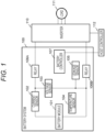
- FIG. 1 is a diagram illustrating a configuration of a battery system to which a storage battery control device according to one embodiment of the present invention is applied.
- a battery system 100 illustrated in FIG. 1 is connected to an inverter 110 and a host controller 112.
- a load 111 is connected to the inverter 110.
- the inverter 110 is a bidirectional inverter that operates under control of the host controller 112.
- the inverter 110 converts DC power supplied from the battery system 100 into AC power and outputs the converted power to the load 111.
- the load 111 is, for example, a three-phase AC motor mounted on a vehicle, and generates a driving force of the vehicle by rotationally driving the load using the AC power supplied from the inverter 110.
- AC power is output from the load 111.
- the inverter 110 converts the AC power output from the load 111 into DC power, and outputs the obtained DC power to the battery system 100 to be stored therein. In this manner, the charge/discharge of the battery system 100 is performed by operating the inverter 110 according to the control of the host controller 112.
- the battery system 100 includes a battery module 101, a current sensor 102, a voltage sensor 103, a temperature sensor 104, a leakage sensor 105, a relay 106A, a relay 106B, and a battery controller 107.
- the battery module 101 is a chargeable/dischargeable storage battery configured by connecting a plurality of unit batteries in series or in series and in parallel.
- the battery module 101 may be divided into two or more groups, and a circuit breaker which can be manually operated may be provided between the groups. In this manner, it is possible to prevent occurrence of an electric shock accident or a short-circuit accident by opening the circuit breaker at the time of assembling, disassembling, or checking the battery system 100.
- the current sensor 102 detects charge/discharge current flowing in the battery module 101.
- the voltage sensor 103 detects voltage of the battery module 101.
- the temperature sensor 104 detects temperature of the battery module 101.
- the leakage sensor 105 detects insulation resistance of the battery module 101.
- the relays 106A and 106B are configured to switch an electrical connection state between the battery module 101 and the inverter 110, and are controlled by the battery controller 107 or the host controller 112.
- the relay 106A is connected between a positive electrode side of the battery module 101 and the inverter 110
- the relay 106B is connected between a negative electrode side of the battery module 101 and the inverter 110.
- any one of the relays 106A and 106B may be omitted.
- a pre-charge relay and a resistor may be provided in parallel with the relay 106A or 106B in order to limit inrush current. In this case, when connecting the battery module 101 and the inverter 110, it is sufficient to turn on the pre-charge relay first, and turn on the relay 106A or 106B and turn off the pre-charge relay after the current becomes sufficiently small.
- the battery controller 107 corresponds to a storage battery control device according to one embodiment of the present invention.
- the battery controller 107 acquires the respective detection results of the current sensor 102, the voltage sensor 103, the temperature sensor 104, and the leakage sensor 105 and controls the battery system 100 based on these detection results.
- the battery controller 107 calculates a state of charge (SOC) and a state of health (SOH) of the battery module 101 based on the detection result of the charge/discharge current obtained by the current sensor 102 and the detection result of the voltage obtained by the voltage sensor 103. Further, charge/discharge control of the battery module 101 and balancing control for equalizing the SOC of each unit cell of the battery module 101 are performed based on these calculation results.
- SOC state of charge
- SOH state of health
- the battery controller 107 determines whether or not the battery module 101 is in a leakage state or in a state where leakage is likely to occur based on the detection result of the insulation resistance obtained by the leakage sensor 105, and stops the operation of the battery system 100 when determining that the battery module 101 is in such states.
- the battery controller 107 can execute various types of processing.
- the battery controller 107 sets a limit value for appropriately maintaining the life of the battery module 101 and determines a timing at which the limit value needs to be output during the charge/discharge control of the battery module 101. Further, the limit value is output to the host controller 112 at the determined timing. Details of the charge/discharge control of the battery module 101 by the battery controller 107 will be described later in more detail.
- the host controller 112 controls operation states of the battery system 100 and the inverter 110 based on various types of information on the battery module 101 transmitted from the battery controller 107.
- the battery information acquisition unit 201 acquires various types of information on a state of the battery module 101 based on the respective detection results of the current sensor 102, the voltage sensor 103, and the temperature sensor 104.
- the battery information acquisition unit 201 acquires, for example, the charge/discharge current of the battery module 101 detected by the current sensor 102, the temperature of the battery module 101 detected by the temperature sensor 104, and the like as information on the battery module 101.
- the SOC of the battery module 101 may be calculated based on the detection result of the charge/discharge current obtained by the current sensor 102 and the detection result of the voltage obtained by the voltage sensor 103, and the calculated SOC may be acquired as the information on the battery module 101.
- the battery information acquisition unit 201 can acquire at least any one of the above-described various types of information relating to the state of the battery module 101. Incidentally, information other than those described above may be acquired as the information on the battery module 101.
- the degradation progression rate calculation unit 202 calculates a degradation progression rate of the battery module 101 based on the information on the battery module 101 acquired by the battery information acquisition unit 201. For example, the degradation progression rate calculation unit 202 records history of the information on the battery module 101 acquired by the battery information acquisition unit 201 in association with the SOH of the battery module 101. It is possible to calculate the degradation progression rate of the battery module 101 by estimating a change of a future SOH based on the information recorded in this manner.
- the timing determination unit 204 determines the timing at which the limit value, set by the limit value setting unit 203, needs to be output to the host controller 112 based on the information on the battery module 101 acquired by the battery information acquisition unit 201. Incidentally, a specific method of determining the timing using the timing determination unit 204 will be described later.
- the limit value output unit 205 outputs the limit value set by the limit value setting unit 203 to the host controller 112 based on the timing determined by the timing determination unit 204.
- the host controller 112 controls the battery system 100 and the inverter 110 according to this limit value and performs the charge/discharge control of the battery module 101.
- FIG. 3 is a flowchart of the charge/discharge control of the battery module 101 using the battery controller 107 according to an aspect useful for understanding the present invention.
- the battery controller 107 executes the charge/discharge control of the battery module 101 at every predetermined processing cycle according to the flowchart of FIG. 3 .
- step S101 the battery controller 107 acquires various types of information on the battery module 101 described above by the battery information acquisition unit 201.
- step S103 the battery controller 107 sets the limit value in the charge/discharge of the battery module 101 using the limit value setting unit 203 based on the degradation proceeding rate of the battery module 101 calculated in step S102.
- step S104 the battery controller 107 calculates the integrated value of each information on the battery module 101 acquired in step S101 using the timing determination unit 204.
- each integrated value is calculated for various types of information described above.
- integrated values are obtained by integrating measurement values obtained at predetermined time intervals, respectively, regarding the charge/discharge current and the temperature.
- charge current and discharge current are distinguished from each other depending on a positive or negative sign of a measurement value, it is preferable to integrate absolute values in order to sum these values.
- integrated values are obtained by integrating measurement values obtained at predetermined time intervals, respectively, regarding the use time and the traveling distance of the vehicle, which is similar to the charge/discharge current and the temperature.
- step S105 the battery controller 107 determines whether or not any integrated value among the integrated values calculated in step S104 is equal to or greater than a predetermined determination threshold using the timing determination unit 204. As a result, when at least one integrated value is equal to or greater than the determination threshold, the timing determination unit 204 notifies the limit value output unit 205 of such a determination result, and the processing proceeds to step S106. On the other hand, when all the integrated values are less than the determination threshold, the processing illustrated in the flowchart of FIG. 3 is ended. In this case, the limit value is not output from the battery controller 107 to the host controller 112.
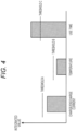
- FIG. 4 is a diagram illustrating a timing determination method performed by the timing determination unit 204 according to an aspect useful for understanding the present invention.
- FIG. 4 illustrates an example in which an integrated value is obtained for each information of the charge/discharge current, the temperature, and the use time of the battery module 101, and the respective integrated values are compared with thresholds A, B, and C, respectively.
- the thresholds A, B, and C represent the above-described determination thresholds set, respectively, regarding the integrated values of the charge/discharge current, the temperature, and the use time. These thresholds can be determined according to characteristics of the battery module 101 and use environment.
- the timing determination unit 204 makes affirmative determination in step S105 of FIG. 3 and causes the processing to proceed to step S106 as described above.
- the battery controller 107 outputs the limit value set in step S103 to the host controller 112 using the limit value output unit 205 in step S106.
- step S107 the battery controller 107 resets the respective integrated values calculated in step S104 to zero using the timing determination unit 204. Accordingly, integration is newly started from the next processing.
- step S107 is executed, the battery controller 107 ends the processing illustrated in the flowchart of FIG. 3 .
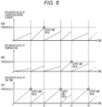
- the battery controller 107 starts the charge/discharge control, the integrated values of the charge/discharge current, the temperature, and the use time increase as illustrated in (a), (b) and (c), respectively. It is assumed that the integrated value of the use time reaches the threshold C at time t1, as a result, as illustrated in (c). At this time, the limit value is output from the battery controller 107 to the host controller 112, and the respective integrated values are reset to zero.
- the timing determination unit 204 calculates integrated values of a plurality of pieces of information on the battery module 101 acquired by the battery information acquisition unit 201, and compares each integrated value with each threshold thereof. As a result, when the integrated value exceeds the threshold regarding at least any one piece of the information, it is possible to determine as the timing at which the limit value needs to be output.
- the limit value calculation unit 206 calculates a limit value for controlling charge/discharge of the battery module 101 based on a degradation progression rate calculated by the degradation progression rate calculation unit 202.
- the limit value calculation unit 206 can calculate the limit value in the same manner as the limit value setting unit 203 sets the limit value.
- the limit value correction unit 208 outputs the limit value that has been used in the charge/discharge control so far directly to the host controller 112 without any correction. In these cases, the host controller 112 continuously performs the charge/discharge control of the battery module 101 according to the limit value that has been used so far.
- FIG. 7 is a functional block diagram of the limit value correction permission unit 207 according to the embodiment of the present invention. As illustrated in FIG. 7 , the limit value correction permission unit 207 is constituted by each functional block of a battery use state estimation unit 301 and a correction permission determination unit 302.
- the correction permission determination unit 302 determines whether or not to permit the correction of the limit value based on the use state of the battery module 101 estimated by the battery use state estimation unit 301 and the use time of the battery module 101. This determination result is output to the limit value correction unit 208.
- FIG. 8 is a diagram illustrating the method of estimating the battery use state based on charge/discharge current. Movement of lithium ions occurs inside the battery module 101 in accordance with charge and discharge. That is, at the time of charge, lithium ions are desorbed from the surface and inside of a positive electrode material and move in an electrolytic solution and diffuse into the material after reaching the surface of the positive electrode material. At the time of discharge, the reverse phenomenon occurs. The number of lithium ions moving in this manner increases as the charge/discharge current increases.
- the electrode material repeatedly expands and shrinks in accordance with the movement of lithium ions, and thus, the electrode material is exposed to a mechanical load as the charge and discharge are repeated. That is, the integrated value of the charge/discharge current correlates with the degradation of the battery module 101.
- the use state of the battery module 101 regarding the charge/discharge current in the battery use state estimation unit 301 by obtaining the integrated value of the charge/discharge current as illustrated in FIG. 8 .
- the charge current and the discharge current may be separately integrated.
- the battery use state estimation unit 301 clears the integrated value of the charge/discharge current that has been integrated so far and starts integration again from zero as illustrated in FIG. 8 . Incidentally, the integration of the charge/discharge current may be continued as it is without clearing the integrated value.
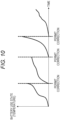
- FIGS. 9 and 10 are views illustrating a method of estimating the battery use state based on the temperature.
- the battery use state estimation unit 301 quantitatively determines a temperature range in which the degradation of the battery module 101 is promoted based on a relationship between battery temperature and promotion of the degradation, grasped in advance, as illustrated in FIG. 9 , and obtains a degradation tendency index indicating a degradation tendency of the battery module 101.
- the degradation tendency index of the battery module 101 exponentially increases as the battery temperature becomes lower or higher.
- the battery use state estimation unit 301 clears the integrated value of the degradation tendency index that has been integrated so far and starts integration again from zero as illustrated in FIG. 10 . Incidentally, the integration of the degradation tendency index may be continued as it is without clearing the integrated value.
- FIGS. 11 and 12 are views illustrating a method of estimating the battery use state based on the SOC.
- a lithium ion secondary battery such as the battery module 101 is used in a high SOC region or a low SOC region.
- a specific SOC region in which the degradation is promoted varies depending on a material used for the battery module 101.
- the battery use state estimation unit 301 quantitatively determines a SOC region in which the degradation of the battery module 101 is promoted based on a relationship between the SOC and promotion of the degradation, grasped in advance, as illustrated in FIG. 11 , and obtains a degradation tendency index indicating a degradation tendency of the battery module 101.
- the degradation tendency index of the battery module 101 exponentially increases as being used in a lower SOC region or a higher SOC region.
- the battery use state estimation unit 301 clears the integrated value of the degradation tendency index that has been integrated so far and starts integration again from zero as illustrated in FIG. 12 . Incidentally, the integration of the degradation tendency index may be continued as it is without clearing the integrated value.
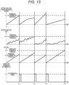
- FIG. 13 is a diagram illustrating an example of a relationship between a battery use state and a correction permission determination result of a limit value.
- FIG. 13 illustrates a case where the determination on correction permission of the limit value is performed based on the battery use state relating to the charge/discharge current and the battery use state relating to the SOC described above, and the use time of the battery module 101.
- the correction permission determination unit 302 permits correction of the limit value. Specifically, the correction permission determination unit 302 integrates the charge/discharge current as the battery use state relating to the charge/discharge current, and sets the degradation tendency index based on the SOC as the battery use state relating to the SOC as illustrated in FIG. 13 . At the same time, the use time of the battery module 101 is integrated as the battery use time.
- the correction permission determination unit 302 resets each integrated value to zero and starts integration again.
- the correction permission determination unit 302 determines that the correction permission determination is made, and outputs the correction permission signal. Thereafter, as the battery use state relating to the SOC exceeds the threshold at time t12 after the battery use time exceeds the threshold, the correction permission determination unit 302 determines that the correction permission determination is made and outputs the correction permission signal. Thereafter, as the battery use time exceeds the threshold at time t13 after the battery use state relating to the charge/discharge current exceeds the threshold, the correction permission determination unit 302 determines that the correction permission determination is made and outputs the correction permission signal.
- the correction permission determination unit 302 determines that the correction permission determination is made and outputs the correction permission signal.
- the compulsory permission threshold is set to a value higher than the above-described permission determination threshold. Accordingly, the correction permission determination unit 302 permits the correction of the limit value when a use frequency of the battery module 101 decreases, for example, since the vehicle on which the battery module 101 is mounted is left for a long period of time.
- the correction permission determination unit 302 permits the correction of the limit value regardless of the battery use state when the battery use time exceeds the compulsory permission threshold.
- FIG. 14 is a flowchart of the charge/discharge control of the battery module 101 using the battery controller 107 according to the embodiment of the present invention.
- the battery controller 107 of the present embodiment executes the charge/discharge control of the battery module 101 at every predetermined processing cycle according to the flowchart of FIG. 14 .
- steps S1001 to S1003 the battery controller 107 executes the same processes, respectively, as steps S101 to S103 of FIG. 3 .
- step S1005 the battery controller 107 calculates the battery use time since the previous correction of the limit value using the battery use state estimation unit 301.
- step S1006 the battery controller 107 determines whether or not the battery use state estimated in step S1004 exceeds the permission determination threshold using the correction permission determination unit 302. As a result, the process proceeds to step S1007 if at least any one of the use states of the battery module 101 regarding the charge/discharge current, the temperature, the SOC, and the like is equal to or greater than the permission determination threshold thereof. On the other hand, if all the battery use states are less than the permission determination thresholds thereof, the process proceeds to step S1008.
- step S1009 the battery controller 107 corrects the limit value used for the charge/discharge control of the battery module 101 based on the limit value set in step S103 using the limit value correction unit 208. Then, the corrected limit value is output to the host controller 112.
- the present invention is not limited to the above-described embodiment.
- Other embodiments conceivable within a technical idea of the present invention are also included within the scope of the present invention, as long as being within the scope of the present claims.
Landscapes
- Engineering & Computer Science (AREA)
- Power Engineering (AREA)
- General Chemical & Material Sciences (AREA)
- Manufacturing & Machinery (AREA)
- Chemical & Material Sciences (AREA)
- Chemical Kinetics & Catalysis (AREA)
- Electrochemistry (AREA)
- Life Sciences & Earth Sciences (AREA)
- Sustainable Development (AREA)
- Sustainable Energy (AREA)
- Transportation (AREA)
- Mechanical Engineering (AREA)
- Microelectronics & Electronic Packaging (AREA)
- Physics & Mathematics (AREA)
- General Physics & Mathematics (AREA)
- Secondary Cells (AREA)
- Charge And Discharge Circuits For Batteries Or The Like (AREA)
- Tests Of Electric Status Of Batteries (AREA)
Description
- The present invention relates to a storage battery control device.
- Conventionally, an on-board battery system, which is mounted on a hybrid electric vehicle (HEV) or a plug-in hybrid electric vehicle (PHEV) and uses a lithium ion secondary battery as a storage battery, has been used. The price of the storage battery in such a vehicle battery system generally occupies a large proportion in the price of the whole vehicle, and it is necessary to replace the storage battery when the life of the storage battery runs out faster than the life of the vehicle, thereby resulting in great cost. For this reason, a battery system, which performs charge/discharge control so as to make the life of the storage battery as long as possible, has been developed in recent years. For example,
PTL 1 discloses a technique of calculating a degradation rate of a storage battery, comparing the calculated degradation rate with a reference degradation rate, and controlling charge/discharge of the storage battery according to a result of the comparison. -
US 2014/339891 A1 discloses a battery controller that performs current limitation in consideration of limitation on other components than a battery main body and the state of health of a battery. When the battery is deteriorated, an allowable average current obtained by subtraction in response to the state of health is used. -
US 2015/207341 A1 discloses a battery system that controls charging and discharging operations of a nickel metal hydride battery, including a temperature sensor detecting a temperature of the nickel metal hydride battery and a controller limiting the charging and discharging operations of the nickel metal hydride battery when a negative electrode reserve capacity of the nickel metal hydride battery is smaller than a target value. -
US 2013/038333 A1 discloses a deterioration degree calculating apparatus for a secondary battery including: obtaining a voltage value at a stop time of charge and discharge of a target secondary battery, obtaining a voltage value at a first start time of charge and discharge after that, obtaining an SOC of the target secondary battery at the stop time or at the start time, obtaining a length of an unused period from the stop time to the start time (an elapsed time), obtaining a self-discharge slope of the target secondary battery by dividing an absolute value of a difference between the voltage value at the start time and the voltage value at the stop time by the elapsed time, obtaining a temperature during an unused period by use of a self-discharge map in which the SOC and the self-discharge slope is recorded for each temperature, calculating a progress degree of deterioration of the target secondary battery during the unused period based on the obtained temperature and elapsed time, and accumulating the calculated deterioration progress degree to accurately calculate the deterioration degree of the secondary battery without continuously consuming electric power during the unused period. -
WO 2015/045505 A1 discloses a battery control system comprising: a current detection unit for detecting the current flowing through a unit battery, a temperature detection unit for detecting the temperature of the unit battery, and a control unit for, based on the history of the current and temperature of the unit battery in a predetermined time window, performing limit control to limit the current of the unit battery so that a current value does not exceed a current limit value. -
US 2013/293200 A1 discloses a control apparatus controlling discharge of a secondary battery such that a discharge power of the secondary battery does not exceed an upper limit value including a current sensor and a controller. -
JP 2003 297435 A -
JP 2014 003826 A -
US 2014/225571 A1 discloses a control device that controls discharge of a nonaqueous secondary battery in order that discharge electric power of the nonaqueous secondary battery does not exceed an upper limit value includes a current sensor and a controller. The controller calculates an evaluation value for evaluating a first deterioration component based on a discharge state detected by using the current sensor. The first deterioration component is a component that reduces output performance of the non-aqueous secondary battery due to an imbalance of ion concentrations in an electrolytic solution caused by discharging the nonaqueous secondary battery. The controller integrates a value obtained by subtracting a correction coefficient from a first integrated value obtained by integrating the evaluation values in past, which exceed a target value, and the evaluation value at present, which exceeds the target value, to calculate a second integrated value. When the second integrated value exceeds a threshold value, the controller reduces the upper limit value. -
US 2013/035813 A1 discloses a vehicle equipped with a battery, an electric motor con-figured so as to generate the driving force of the vehicle by use of the electric power stored in the battery, a charger configured so as to supply the electric power outputted from the power supply outside of the vehicle to the battery, and an ECU configured so as to control the state of charge of the battery when the battery is charged. The ECU calculates an index value indicating the state of charge of the battery, and sets the control range thereof. -
JP 2013 065481 A -
JP 2008 024124 A -
WO 2015/001751 A1 discloses a vehicle storage battery management device provided with a charge level acquisition unit, a power amount acquisition unit, and a power capacity derivation unit. The charge level acquisition unit acquires charge level data indicating the ratio of the capacity of a storage battery mounted in an electric vehicle to a fully charged state. - PTL 1:
JP 2007-323999 A - In the charge/discharge control of the storage battery as in
PTL 1, it is necessary to determine a timing for performing the charge/discharge control in consideration of a period until a degradation state of the storage battery is affected by a change of a control state with respect to the storage battery. However, such a point is not sufficiently taken into consideration in the related art, and thus, it is difficult to perform the charge/discharge control of the storage battery at an appropriate timing. - A storage battery control device according to one aspect of the present invention includes: a battery information acquisition unit that acquires information on a storage battery; a degradation progression rate calculation unit that calculates a degradation progression rate of the storage battery based on the information acquired by the battery information acquisition unit; a limit value calculation unit that calculates a limit value for controlling charge/discharge of the storage battery based on the degradation progression rate calculated by the degradation progression rate calculation unit; a battery use state estimation unit that estimates a use state of the storage battery based on the information acquired by the battery information acquisition unit; a correction permission determination unit that determines whether or not to permit correction of the limit value based on the use state of the storage battery estimated by the battery use state estimation unit and use time of the storage battery; and a limit value correction unit that corrects the set limit value based on the limit value obtained by the limit value calculation unit and a determination result of the correction permission determination unit.
- According to this aspect of the present invention, the battery information acquisition unit acquires at least any one piece of information of charging/discharging current of the storage battery, temperature of the storage battery, and a charge state of the storage battery.
- The battery use state estimation unit estimates at least any one of a use state of the storage battery relating to the charge/discharge current, a use state of the storage battery relating to the temperature, and a use state of the storage battery relating to the charge state.
- The correction permission determination unit permits correction of the limit value when at least any one estimated value of the use state of the storage battery relating to the charge/discharge current, the use state of the storage battery relating to the temperature, and the use state of the storage battery relating to the charge state is greater than a predetermined compulsory permission threshold, set in advance for each estimated value, and the use time of the storage battery is equal to or longer than predetermined permission determination time.
- When the use time of the storage battery is equal to or longer than predetermined compulsory permission time, the correction permission determination unit determines to permit correction of the limit value regardless of the use state of the storage battery and outputs a respective correction permission signal as the determination result.
- According to the present invention, it is possible to perform the charge/discharge control of the storage battery at an appropriate timing.
-
- [
FIG. 1] FIG. 1 is a diagram illustrating a configuration of a battery system to which a storage battery control device according to an embodiment of the present invention is applied. - [
FIG. 2] FIG. 2 is a functional block diagram of a battery controller according to an aspect useful for understanding the present invention. - [
FIG. 3] FIG. 3 is a flowchart of charge/discharge control of a battery module according to an aspect useful for understanding the present invention. - [
FIG. 4] FIG. 4 is a diagram illustrating a timing determination method according to an aspect useful for understanding the present invention. - [
FIG. 5] FIG. 5 is a diagram illustrating an example of a relationship between a change of an integrated value and a limit value output timing. - [
FIG. 6] FIG. 6 is a functional block diagram of a battery controller according to an embodiment of the present invention. - [
FIG. 7] FIG. 7 is a functional block diagram of a limit value correction permission unit according to the embodiment of the present invention. - [
FIG. 8] FIG. 8 is a diagram illustrating a method of estimating a battery use state based on charge/discharge current. - [
FIG. 9] FIG. 9 is a view illustrating a method of estimating a battery use state based on temperature. - [
FIG. 10] FIG. 10 is a diagram illustrating the method of estimating the battery use state based on the temperature. - [
FIG. 11] FIG. 11 is a diagram illustrating a method of estimating a battery use state based on an SOC. - [
FIG. 12] FIG. 12 is a diagram illustrating the method of estimating the battery use state based on the SOC. - [
FIG. 13] FIG. 13 is a diagram illustrating an example of a relationship between a battery use state and a correction permission determination result of a limit value. - [
FIG. 14] FIG. 14 is a flowchart of charge/discharge control of a battery module according to the embodiment of the present invention. - Hereinafter, one embodiment of the present invention will be described with reference to the drawings.
-
FIG. 1 is a diagram illustrating a configuration of a battery system to which a storage battery control device according to one embodiment of the present invention is applied. Abattery system 100 illustrated inFIG. 1 is connected to aninverter 110 and ahost controller 112. Aload 111 is connected to theinverter 110. - The
inverter 110 is a bidirectional inverter that operates under control of thehost controller 112. Theinverter 110 converts DC power supplied from thebattery system 100 into AC power and outputs the converted power to theload 111. Theload 111 is, for example, a three-phase AC motor mounted on a vehicle, and generates a driving force of the vehicle by rotationally driving the load using the AC power supplied from theinverter 110. In addition, when regenerative power generation is performed by operating theload 111 as a generator using kinetic energy of the vehicle, AC power is output from theload 111. In this case, theinverter 110 converts the AC power output from theload 111 into DC power, and outputs the obtained DC power to thebattery system 100 to be stored therein. In this manner, the charge/discharge of thebattery system 100 is performed by operating theinverter 110 according to the control of thehost controller 112. - Incidentally, the present invention is not limited to the configuration illustrated in
FIG. 1 as long as the charge/discharge of thebattery system 100 can be appropriately controlled. For example, a charging system different from theinverter 110 may be connected to thebattery system 100 such that charge of thebattery system 100 is performed as needed using this charging system. - The
battery system 100 includes abattery module 101, acurrent sensor 102, avoltage sensor 103, atemperature sensor 104, aleakage sensor 105, arelay 106A, arelay 106B, and abattery controller 107. - The
battery module 101 is a chargeable/dischargeable storage battery configured by connecting a plurality of unit batteries in series or in series and in parallel. Incidentally, thebattery module 101 may be divided into two or more groups, and a circuit breaker which can be manually operated may be provided between the groups. In this manner, it is possible to prevent occurrence of an electric shock accident or a short-circuit accident by opening the circuit breaker at the time of assembling, disassembling, or checking thebattery system 100. - The
current sensor 102 detects charge/discharge current flowing in thebattery module 101. Thevoltage sensor 103 detects voltage of thebattery module 101. Thetemperature sensor 104 detects temperature of thebattery module 101. Theleakage sensor 105 detects insulation resistance of thebattery module 101. Each detection result of thecurrent sensor 102, thevoltage sensor 103, thetemperature sensor 104, and theleakage sensor 105 is output to thebattery controller 107. - The
relays battery module 101 and theinverter 110, and are controlled by thebattery controller 107 or thehost controller 112. Therelay 106A is connected between a positive electrode side of thebattery module 101 and theinverter 110, and therelay 106B is connected between a negative electrode side of thebattery module 101 and theinverter 110. Incidentally, any one of therelays relay battery module 101 and theinverter 110, it is sufficient to turn on the pre-charge relay first, and turn on therelay - The
battery controller 107 corresponds to a storage battery control device according to one embodiment of the present invention. Thebattery controller 107 acquires the respective detection results of thecurrent sensor 102, thevoltage sensor 103, thetemperature sensor 104, and theleakage sensor 105 and controls thebattery system 100 based on these detection results. For example, thebattery controller 107 calculates a state of charge (SOC) and a state of health (SOH) of thebattery module 101 based on the detection result of the charge/discharge current obtained by thecurrent sensor 102 and the detection result of the voltage obtained by thevoltage sensor 103. Further, charge/discharge control of thebattery module 101 and balancing control for equalizing the SOC of each unit cell of thebattery module 101 are performed based on these calculation results. In addition, thebattery controller 107 determines whether or not thebattery module 101 is in a leakage state or in a state where leakage is likely to occur based on the detection result of the insulation resistance obtained by theleakage sensor 105, and stops the operation of thebattery system 100 when determining that thebattery module 101 is in such states. In addition, thebattery controller 107 can execute various types of processing. - Incidentally, the
battery controller 107 sets a limit value for appropriately maintaining the life of thebattery module 101 and determines a timing at which the limit value needs to be output during the charge/discharge control of thebattery module 101. Further, the limit value is output to thehost controller 112 at the determined timing. Details of the charge/discharge control of thebattery module 101 by thebattery controller 107 will be described later in more detail. - The
host controller 112 controls operation states of thebattery system 100 and theinverter 110 based on various types of information on thebattery module 101 transmitted from thebattery controller 107. - Next, details of the charge/discharge control of the
battery module 101 by thebattery controller 107 will be described.FIG. 2 is a functional block diagram of thebattery controller 107 according to an aspect useful for understanding the present invention. As illustrated inFIG. 2 , thebattery controller 107 is constituted by each functional block of a batteryinformation acquisition unit 201, a degradation progressionrate calculation unit 202, a limitvalue setting unit 203, atiming determination unit 204, and a limitvalue output unit 205. Thebattery controller 107 can realize these functional blocks, for example, by executing a predetermined program using a CPU. - The battery
information acquisition unit 201 acquires various types of information on a state of thebattery module 101 based on the respective detection results of thecurrent sensor 102, thevoltage sensor 103, and thetemperature sensor 104. The batteryinformation acquisition unit 201 acquires, for example, the charge/discharge current of thebattery module 101 detected by thecurrent sensor 102, the temperature of thebattery module 101 detected by thetemperature sensor 104, and the like as information on thebattery module 101. In addition, the SOC of thebattery module 101 may be calculated based on the detection result of the charge/discharge current obtained by thecurrent sensor 102 and the detection result of the voltage obtained by thevoltage sensor 103, and the calculated SOC may be acquired as the information on thebattery module 101. Further, it is also possible to acquire use time of thebattery module 101 measured using a timer (not illustrated) built in thebattery controller 107, traveling distance of the vehicle on which thebattery module 101 is mounted, and the like as the information on thebattery module 101. That is, the batteryinformation acquisition unit 201 can acquire at least any one of the above-described various types of information relating to the state of thebattery module 101. Incidentally, information other than those described above may be acquired as the information on thebattery module 101. - The degradation progression
rate calculation unit 202 calculates a degradation progression rate of thebattery module 101 based on the information on thebattery module 101 acquired by the batteryinformation acquisition unit 201. For example, the degradation progressionrate calculation unit 202 records history of the information on thebattery module 101 acquired by the batteryinformation acquisition unit 201 in association with the SOH of thebattery module 101. It is possible to calculate the degradation progression rate of thebattery module 101 by estimating a change of a future SOH based on the information recorded in this manner. - The limit
value setting unit 203 sets a limit value for controlling the charge/discharge of thebattery module 101 based on the degradation progression rate calculated by the degradation progressionrate calculation unit 202. For example, the limitvalue setting unit 203 obtains a life prediction value of thebattery module 101 based on the calculated degradation progression rate, and compares the life prediction value with a life target value set in advance. As a result, if a gap between the life target value and the life prediction value is large, the setting of the limit value regarding the charge/discharge of thebattery module 101 is changed in a retrenching direction or a relaxing direction such that the gap decreases. At this time, it is possible to use allowable charge/discharge current, allowable charge/discharge power, an allowable temperature range, an allowable SOC range, and the like as the limit value of thebattery module 101. - The
timing determination unit 204 determines the timing at which the limit value, set by the limitvalue setting unit 203, needs to be output to thehost controller 112 based on the information on thebattery module 101 acquired by the batteryinformation acquisition unit 201. Incidentally, a specific method of determining the timing using thetiming determination unit 204 will be described later. - The limit
value output unit 205 outputs the limit value set by the limitvalue setting unit 203 to thehost controller 112 based on the timing determined by thetiming determination unit 204. When the limit value is output from the limitvalue output unit 205, thehost controller 112 controls thebattery system 100 and theinverter 110 according to this limit value and performs the charge/discharge control of thebattery module 101. -
FIG. 3 is a flowchart of the charge/discharge control of thebattery module 101 using thebattery controller 107 according to an aspect useful for understanding the present invention. Thebattery controller 107 executes the charge/discharge control of thebattery module 101 at every predetermined processing cycle according to the flowchart ofFIG. 3 . - In step S101, the
battery controller 107 acquires various types of information on thebattery module 101 described above by the batteryinformation acquisition unit 201. - In step S102, the
battery controller 107 calculates the degradation progression rate of thebattery module 101 using the degradation progressionrate calculation unit 202 based on the information on thebattery module 101 acquired in step S101. - In step S103, the
battery controller 107 sets the limit value in the charge/discharge of thebattery module 101 using the limitvalue setting unit 203 based on the degradation proceeding rate of thebattery module 101 calculated in step S102. - In step S104, the
battery controller 107 calculates the integrated value of each information on thebattery module 101 acquired in step S101 using thetiming determination unit 204. Here, each integrated value is calculated for various types of information described above. Specifically, integrated values are obtained by integrating measurement values obtained at predetermined time intervals, respectively, regarding the charge/discharge current and the temperature. Incidentally, when charge current and discharge current are distinguished from each other depending on a positive or negative sign of a measurement value, it is preferable to integrate absolute values in order to sum these values. In addition, integrated values are obtained by integrating measurement values obtained at predetermined time intervals, respectively, regarding the use time and the traveling distance of the vehicle, which is similar to the charge/discharge current and the temperature. On the other hand, it is preferable to integrate absolute values of change amount of the SOC every measurement time, rather than directly integrating the SOC obtained at predetermined time intervals. - In step S105, the
battery controller 107 determines whether or not any integrated value among the integrated values calculated in step S104 is equal to or greater than a predetermined determination threshold using thetiming determination unit 204. As a result, when at least one integrated value is equal to or greater than the determination threshold, thetiming determination unit 204 notifies the limitvalue output unit 205 of such a determination result, and the processing proceeds to step S106. On the other hand, when all the integrated values are less than the determination threshold, the processing illustrated in the flowchart ofFIG. 3 is ended. In this case, the limit value is not output from thebattery controller 107 to thehost controller 112. -
FIG. 4 is a diagram illustrating a timing determination method performed by thetiming determination unit 204 according to an aspect useful for understanding the present invention.FIG. 4 illustrates an example in which an integrated value is obtained for each information of the charge/discharge current, the temperature, and the use time of thebattery module 101, and the respective integrated values are compared with thresholds A, B, and C, respectively. Incidentally, the thresholds A, B, and C represent the above-described determination thresholds set, respectively, regarding the integrated values of the charge/discharge current, the temperature, and the use time. These thresholds can be determined according to characteristics of thebattery module 101 and use environment. - In the example of
FIG. 4 , the integrated value of the charge/discharge current is less than the threshold A, and the integrated value of the temperature is less than the threshold B. On the other hand, the integrated value of the use time is equal to or greater than the threshold C. Thus, thetiming determination unit 204 makes affirmative determination in step S105 ofFIG. 3 and causes the processing to proceed to step S106 as described above. - Returning to the description of
FIG. 3 , thebattery controller 107 outputs the limit value set in step S103 to thehost controller 112 using the limitvalue output unit 205 in step S106. - In step S107, the
battery controller 107 resets the respective integrated values calculated in step S104 to zero using thetiming determination unit 204. Accordingly, integration is newly started from the next processing. After step S107 is executed, thebattery controller 107 ends the processing illustrated in the flowchart ofFIG. 3 . -
FIG. 5 is a diagram illustrating an example of a relationship between a change of an integrated value and a limit value output timing. InFIG. 5 , (a) illustrates how the integrated value of charge/discharge current changes, (b) illustrates how the integrated value of temperature changes, and (c) illustrates how the use time changes. - When the
battery controller 107 starts the charge/discharge control, the integrated values of the charge/discharge current, the temperature, and the use time increase as illustrated in (a), (b) and (c), respectively. It is assumed that the integrated value of the use time reaches the threshold C at time t1, as a result, as illustrated in (c). At this time, the limit value is output from thebattery controller 107 to thehost controller 112, and the respective integrated values are reset to zero. - After time t1, the respective integrated values of the charge/discharge current, the temperature, and the use time rise again. Here, it is assumed that the integrated value of the charge/discharge current reaches the threshold A at time t2, as a result, as illustrated in (a). At this time, the limit value is output from the
battery controller 107 to thehost controller 112, and the respective integrated values are reset to zero. - Even after time t2, the same processing as described above is repeated. That is, when the integrated value of the use time reaches the threshold C at time t3 as illustrated in (c), the limit value is output from the
battery controller 107 to thehost controller 112, and the respective integrated values are reset to zero. In addition, when the integrated value of the temperature reaches the threshold B at time t4 as illustrated in (b), the limit value is output from thebattery controller 107 to thehost controller 112, and the respective integrated values are reset to zero. Further, when the integrated value of the use time reaches the threshold C at time t5 as illustrated in (c), the limit value is output from thebattery controller 107 to thehost controller 112, and the respective integrated values are reset to zero. Thereafter, whenever any integrated value reaches the threshold thereof, the limit value is output from thebattery controller 107 to thehost controller 112, and the respective integrated values are reset to zero in the same manner. - Although the description has been given in the above-described example by exemplifying the respective integrated values of the charge/discharge current, the temperature, and the use time, the same description applies to another information of the
battery modules 101. That is, thetiming determination unit 204 calculates integrated values of a plurality of pieces of information on thebattery module 101 acquired by the batteryinformation acquisition unit 201, and compares each integrated value with each threshold thereof. As a result, when the integrated value exceeds the threshold regarding at least any one piece of the information, it is possible to determine as the timing at which the limit value needs to be output. - The following operational effects are achieved.
-
- (1) The
battery controller 107 is constituted by the batteryinformation acquisition unit 201, the degradation progressionrate calculation unit 202, the limitvalue setting unit 203, thetiming determination unit 204, and the limitvalue output unit 205. The batteryinformation acquisition unit 201 acquires the information on thebattery module 101 which is the storage battery (step S101). The degradation progressionrate calculation unit 202 calculates the degradation progression rate of thebattery module 101 based on the information acquired by the battery information acquisition unit 201 (step S102). The limitvalue setting unit 203 sets the limit value for controlling the charge/discharge of thebattery module 101 based on the degradation progression rate calculated by the degradation progression rate calculation unit 202 (step S103). Thetiming determination unit 204 determines the timing at which the limit value needs to be output based on the information acquired by the battery information acquisition unit 201 (steps S104 and S105). The limitvalue output unit 205 outputs the limit value based on the timing determined by the timing determination unit 204 (step S106). In this manner, it is possible to perform the charge/discharge control of thebattery module 101 at an appropriate timing. - (2) The battery
information acquisition unit 201 can acquire at least one of the charge/discharge current of thebattery module 101, the temperature of thebattery module 101, the use time of thebattery module 101, and the charge state of thebattery module 101 in step S101. Further, the batteryinformation acquisition unit 201 can also acquire the travel distance of the vehicle on which thebattery module 101 is mounted as the information on thebattery module 101 in step S101. In this manner, it is possible to acquire various types of information relating to the state of thebattery module 101. - (3) The
timing determination unit 204 compares the integrated value of information with the predetermined threshold, and determines as the timing at which the limit value needs to be output when the integrated value exceeds the threshold in step S105. In this manner, it is possible to reliably and easily determine the timing at which the limit value needs to be output. - (4) The battery
information acquisition unit 201 can acquire the plurality of pieces of information on thebattery module 101 in step S101. In this case, thetiming determination unit 204 calculates the respective integrated values of the plurality of pieces of information acquired by the batteryinformation acquisition unit 201 in step S104. Then, it is determined as the timing at which the limit value needs to be output when the integrated value exceeds the threshold regarding at least any one piece of information in step S105. In this manner, it is possible to more appropriately determine the timing at which the limit value needs to be output. - An embodiment of the present invention will be described next. In the present embodiment, a description will be given regarding an example in which charge/discharge control different from that aspects useful for understanding the present invention described above is performed in the
battery controller 107 illustrated inFIG. 1 .FIG. 6 is a functional block diagram of thebattery controller 107 according to the embodiment of the present invention. As illustrated inFIG. 6 , thebattery controller 107 of the present embodiment is constituted by each functional block of a limitvalue calculation unit 206, a limit valuecorrection permission unit 207, and a limitvalue correction unit 208 instead of the limitvalue setting unit 203, thetiming determination unit 204, and the limitvalue output unit 205 inFIG. 2 . Thebattery controller 107 can realize these functional blocks, for example, by executing a predetermined program using a CPU. - The limit
value calculation unit 206 calculates a limit value for controlling charge/discharge of thebattery module 101 based on a degradation progression rate calculated by the degradation progressionrate calculation unit 202. The limitvalue calculation unit 206 can calculate the limit value in the same manner as the limitvalue setting unit 203 sets the limit value. - The limit value
correction permission unit 207 determines whether or not to permit correction of the limit value, which is currently set, based on each piece of information such as current, temperature, an SOC, traveling distance, use time, and the like acquired by the batteryinformation acquisition unit 201 as information on thebattery module 101. Incidentally, a specific determination method using the limit valuecorrection permission unit 207 will be described later. - When the limit value
correction permission unit 207 permits the correction of the limit value, the limitvalue correction unit 208 corrects the limit value to be used for charge/discharge control of thebattery module 101 based on the limit value obtained by the limitvalue calculation unit 206. Specifically, the limitvalue correction unit 208 corrects the limit value when the latest limit value obtained by the limitvalue calculation unit 206 is different from the limit value set in the current charge/discharge control and the limit valuecorrection permission unit 207 has permitted the correction of the limit value. Then, the corrected limit value is output to thehost controller 112. When the limit value is corrected by the limitvalue correction unit 208, thehost controller 112 controls thebattery system 100 and theinverter 110 according to this corrected limit value and performs the charge/discharge control of thebattery module 101. Incidentally, when the correction of the limit value has not been permitted by the limit valuecorrection permission unit 207 or when the limit value obtained by the limitvalue calculation unit 206 is not changed, the limitvalue correction unit 208 outputs the limit value that has been used in the charge/discharge control so far directly to thehost controller 112 without any correction. In these cases, thehost controller 112 continuously performs the charge/discharge control of thebattery module 101 according to the limit value that has been used so far. -
FIG. 7 is a functional block diagram of the limit valuecorrection permission unit 207 according to the embodiment of the present invention. As illustrated inFIG. 7 , the limit valuecorrection permission unit 207 is constituted by each functional block of a battery usestate estimation unit 301 and a correctionpermission determination unit 302. - The battery use
state estimation unit 301 acquires the information such as the current, the temperature, the SOC, and the use time of thebattery module 101 and the travel distance of a vehicle on which thebattery module 101 is mounted from the batteryinformation acquisition unit 201. Then, a use state of thebattery module 101 is estimated based on these pieces of information. - The correction
permission determination unit 302 determines whether or not to permit the correction of the limit value based on the use state of thebattery module 101 estimated by the battery usestate estimation unit 301 and the use time of thebattery module 101. This determination result is output to the limitvalue correction unit 208. - Next, a method of estimating the use state of the
battery module 101 in the battery usestate estimation unit 301 will be described.FIG. 8 is a diagram illustrating the method of estimating the battery use state based on charge/discharge current. Movement of lithium ions occurs inside thebattery module 101 in accordance with charge and discharge. That is, at the time of charge, lithium ions are desorbed from the surface and inside of a positive electrode material and move in an electrolytic solution and diffuse into the material after reaching the surface of the positive electrode material. At the time of discharge, the reverse phenomenon occurs. The number of lithium ions moving in this manner increases as the charge/discharge current increases. In addition, the electrode material repeatedly expands and shrinks in accordance with the movement of lithium ions, and thus, the electrode material is exposed to a mechanical load as the charge and discharge are repeated. That is, the integrated value of the charge/discharge current correlates with the degradation of thebattery module 101. Thus, it is possible to estimate the use state of thebattery module 101 regarding the charge/discharge current in the battery usestate estimation unit 301 by obtaining the integrated value of the charge/discharge current as illustrated inFIG. 8 . Incidentally, when a sign of a value of the charge/discharge current varies depending on a flow direction of current, it is preferable to estimate the use state of thebattery module 101 by integrating an absolute value of the charge/discharge current. Alternatively, the charge current and the discharge current may be separately integrated. - When the correction
permission determination unit 302 permits the correction of the limit value, the battery usestate estimation unit 301 clears the integrated value of the charge/discharge current that has been integrated so far and starts integration again from zero as illustrated inFIG. 8 . Incidentally, the integration of the charge/discharge current may be continued as it is without clearing the integrated value. -
FIGS. 9 and10 are views illustrating a method of estimating the battery use state based on the temperature. In general, it is known that degradation is promoted when a lithium ion secondary battery such as thebattery module 101 is used at high temperature or low temperature. A specific temperature condition at which the degradation is promoted varies depending on a material used for thebattery module 101. Thus, the battery usestate estimation unit 301 quantitatively determines a temperature range in which the degradation of thebattery module 101 is promoted based on a relationship between battery temperature and promotion of the degradation, grasped in advance, as illustrated inFIG. 9 , and obtains a degradation tendency index indicating a degradation tendency of thebattery module 101. In the example illustrated inFIG. 9 , the degradation tendency index of thebattery module 101 exponentially increases as the battery temperature becomes lower or higher. - It is possible to estimate the use state of the
battery module 101 regarding the temperature in the battery usestate estimation unit 301 by obtaining an integrated value of the degradation tendency index based on the battery temperature as illustrated inFIG. 10 . Although the description has been given regarding the example in which the relationship between the battery temperature and the degradation promotion is exponential, the method of estimating the use state of thebattery module 101 regarding the temperature is not limited thereto. Here, it is important to be capable of estimating the use state of thebattery module 101 regarding the temperature, based on the known relationship between the battery temperature and the degradation tendency. - When the correction
permission determination unit 302 permits the correction of the limit value, the battery usestate estimation unit 301 clears the integrated value of the degradation tendency index that has been integrated so far and starts integration again from zero as illustrated inFIG. 10 . Incidentally, the integration of the degradation tendency index may be continued as it is without clearing the integrated value. -
FIGS. 11 and12 are views illustrating a method of estimating the battery use state based on the SOC. In general, it is known that degradation is promoted when a lithium ion secondary battery such as thebattery module 101 is used in a high SOC region or a low SOC region. A specific SOC region in which the degradation is promoted varies depending on a material used for thebattery module 101. Thus, the battery usestate estimation unit 301 quantitatively determines a SOC region in which the degradation of thebattery module 101 is promoted based on a relationship between the SOC and promotion of the degradation, grasped in advance, as illustrated inFIG. 11 , and obtains a degradation tendency index indicating a degradation tendency of thebattery module 101. In the example illustrated inFIG. 11 , the degradation tendency index of thebattery module 101 exponentially increases as being used in a lower SOC region or a higher SOC region. - It is possible to estimate the use state of the
battery module 101 regarding the SOC in the battery usestate estimation unit 301 by obtaining an integrated value of the degradation tendency index based on the SOC as illustrated inFIG. 12 . Although the description has been given regarding the example in which the relationship between the SOC and the degradation promotion is exponential, the method of estimating the use state of thebattery module 101 regarding the SOC is not limited thereto. Here, it is also important to be capable of estimating the use state of thebattery module 101 relating to the SOC, based on the known relationship between the SOC and the degradation tendency, which is similar to the case of the temperature described above. - When the correction
permission determination unit 302 permits the correction of the limit value, the battery usestate estimation unit 301 clears the integrated value of the degradation tendency index that has been integrated so far and starts integration again from zero as illustrated inFIG. 12 . Incidentally, the integration of the degradation tendency index may be continued as it is without clearing the integrated value. - Next, a description will be given regarding a method of performing determination on correction permission of the limit value in the correction
permission determination unit 302 based on the use state of thebattery module 101 estimated by the battery usestate estimation unit 301.FIG. 13 is a diagram illustrating an example of a relationship between a battery use state and a correction permission determination result of a limit value.FIG. 13 illustrates a case where the determination on correction permission of the limit value is performed based on the battery use state relating to the charge/discharge current and the battery use state relating to the SOC described above, and the use time of thebattery module 101. Although a detailed description will be omitted, the same description also applies to other use conditions. - When the use of the
battery module 101 progresses from a change of a previous limit value and it is determined that an effect of the change is reflected in a change of a degradation state of thebattery module 101, the correctionpermission determination unit 302 permits correction of the limit value. Specifically, the correctionpermission determination unit 302 integrates the charge/discharge current as the battery use state relating to the charge/discharge current, and sets the degradation tendency index based on the SOC as the battery use state relating to the SOC as illustrated inFIG. 13 . At the same time, the use time of thebattery module 101 is integrated as the battery use time. Then, when at least any one of the battery use state relating to the charge/discharge current or the battery use state relating to the SOC exceeds each predetermined permission determination threshold thereof set in advance and the battery use time exceeds a predetermined permission determination threshold, it is determined that the correction permission determination has been made and outputs a predetermined correction permission signal. After outputting the correction permission signal, the correctionpermission determination unit 302 resets each integrated value to zero and starts integration again. - In the example of
FIG. 13 , as the battery use state relating to the charge/discharge current exceeds the threshold at time t11 after the battery use time exceeds the threshold, the correctionpermission determination unit 302 determines that the correction permission determination is made, and outputs the correction permission signal. Thereafter, as the battery use state relating to the SOC exceeds the threshold at time t12 after the battery use time exceeds the threshold, the correctionpermission determination unit 302 determines that the correction permission determination is made and outputs the correction permission signal. Thereafter, as the battery use time exceeds the threshold at time t13 after the battery use state relating to the charge/discharge current exceeds the threshold, the correctionpermission determination unit 302 determines that the correction permission determination is made and outputs the correction permission signal. That is, in this case, it is determined that a sufficient time has not elapsed since the previous correction of the limit value until the battery use time exceeds the threshold after the value of the battery use state relating to the charge/discharge current exceeds the threshold, and the correction permission determination is not made. Thereafter, when the battery use time reaches the threshold, the correction permission determination is made. - Incidentally, at time t14, neither the battery use state relating to the charge/discharge current nor the battery use state relating to the SOC exceeds the threshold, but the battery use time exceeds a compulsory permission threshold. Thus, the correction
permission determination unit 302 determines that the correction permission determination is made and outputs the correction permission signal. The compulsory permission threshold is set to a value higher than the above-described permission determination threshold. Accordingly, the correctionpermission determination unit 302 permits the correction of the limit value when a use frequency of thebattery module 101 decreases, for example, since the vehicle on which thebattery module 101 is mounted is left for a long period of time. That is, when the use frequency of thebattery module 101 is low, the progress of degradation over time of thebattery module 101 with the lapse of time is concerned even if the battery use state such as the charge/discharge current, the temperature, the SOC, and the traveling distance does not increase. In consideration of this, the correctionpermission determination unit 302 permits the correction of the limit value regardless of the battery use state when the battery use time exceeds the compulsory permission threshold. -
FIG. 14 is a flowchart of the charge/discharge control of thebattery module 101 using thebattery controller 107 according to the embodiment of the present invention. Thebattery controller 107 of the present embodiment executes the charge/discharge control of thebattery module 101 at every predetermined processing cycle according to the flowchart ofFIG. 14 . - In steps S1001 to S1003, the
battery controller 107 executes the same processes, respectively, as steps S101 to S103 ofFIG. 3 . - In step S1004, the
battery controller 107 estimates the use state of thebattery module 101 using the battery usestate estimation unit 301 based on the information on thebattery module 101 acquired in step S1001. Here, the use states of thebattery module 101 regarding the charge/discharge current, the temperature, the SOC, and the like are estimated using the methods described with reference toFIGS. 8 to 12 , respectively. - In step S1005, the
battery controller 107 calculates the battery use time since the previous correction of the limit value using the battery usestate estimation unit 301. - In step S1006, the
battery controller 107 determines whether or not the battery use state estimated in step S1004 exceeds the permission determination threshold using the correctionpermission determination unit 302. As a result, the process proceeds to step S1007 if at least any one of the use states of thebattery module 101 regarding the charge/discharge current, the temperature, the SOC, and the like is equal to or greater than the permission determination threshold thereof. On the other hand, if all the battery use states are less than the permission determination thresholds thereof, the process proceeds to step S1008. - In step S1007, the
battery controller 107 determines whether or not the battery use time calculated in step S1005 exceeds the permission determination threshold using the correctionpermission determination unit 302. As a result, the process proceeds to step S1009 if the battery use time is equal to or longer than the permission determination threshold. On the other hand, if the battery use time is less than the permission determination threshold, the process returns to step S1001, and the processes of step S1001 and the subsequent steps are repeated. In this case, the correction of the limit value is not performed. - In step S1008, the
battery controller 107 determines whether or not the battery use time calculated in step S1005 exceeds the compulsory permission threshold using the correctionpermission determination unit 302. As a result, the process proceeds to step S1009 if the battery use time is equal to or greater than the compulsory permission threshold. On the other hand, if the battery use time is less than the compulsory permission threshold, the process returns to step S1001, and the processes of step S1001 and the subsequent steps are repeated. Even in this case, the correction of the limit value is not performed. - In step S1009, the
battery controller 107 corrects the limit value used for the charge/discharge control of thebattery module 101 based on the limit value set in step S103 using the limitvalue correction unit 208. Then, the corrected limit value is output to thehost controller 112. - In step S1010, the
battery controller 107 resets each of the battery use state estimated in step S1004 and the battery use time calculated in step S1005 to zero using the battery usestate estimation unit 301. After executing step S1010, thebattery controller 107 ends the processing illustrated in the flowchart ofFIG. 14 . - According to the embodiment of the present invention described above, the following operational effects are achieved.
-
- (1) The
battery controller 107 includes the batteryinformation acquisition unit 201, the degradation progressionrate calculation unit 202, the limitvalue calculation unit 206, the battery usestate estimation unit 301, the correctionpermission determination unit 302, and the limitvalue correction unit 208. The batteryinformation acquisition unit 201 acquires the information on thebattery module 101 which is the storage battery (step S1001). The degradation progressionrate calculation unit 202 calculates the degradation progression rate of thebattery module 101 based on the information acquired by the battery information acquisition unit 201 (step S1002). The limitvalue calculation unit 206 calculates a limit value for controlling charge/discharge of thebattery module 101 based on a degradation progression rate calculated by the degradation progression rate calculation unit 202 (step S1003). The battery usestate estimation unit 301 estimates the use state of thebattery module 101 based on the information acquired by the battery information acquisition unit 201 (step S1004) . The correctionpermission determination unit 302 determines whether or not to permit the correction of the limit value based on the use state of thebattery module 101 estimated by the battery usestate estimation unit 301 and the use time of the battery module 101 (steps S1006 to S1008). The limitvalue correction unit 208 corrects the set limit value based on the limit value obtained by the limitvalue calculation unit 206 and the determination result obtained by the correction permission determination unit 302 (step S1009) . In this manner, it is possible to perform the charge/discharge control of thebattery module 101 at an appropriate timing, which is similar to the aspects useful for understanding the present invention described above. - (2) The battery
information acquisition unit 201 acquires at least one of the charge/discharge current of thebattery module 101, the temperature of thebattery module 101, and the charge state of thebattery module 101 in step S1001. In step S1004, the battery usestate estimation unit 301 estimates at least any one of the use state of thebattery module 101 relating to the charge/discharge current, the use state of thebattery module 101 relating to the temperature, and the use state of thebattery module 101 relating to the charge state. The correctionpermission determination unit 302 permits the correction of the limit value in step S1009 when it is determined in step S1006 that at least any one estimated value of the use state of thebattery module 101 relating to the charge/discharge current, the use state of thebattery module 101 relating to the temperature, and the use state of thebattery module 101 relating to the charge state is greater than the predetermined threshold set in advance for each estimated value and it is determined in step S1007 that the use time of thebattery module 101 is equal to or longer than the predetermined permission determination time. In this manner, it is possible to permit the correction of the limit value at an appropriate timing. - (3) When it is determined in step S1008 that the use time of the
battery module 101 is equal to or longer than the predetermined compulsory permission time, the correctionpermission determination unit 302 permits the correction of the limit value in step S1009 regardless of the use state of thebattery module 101. In this manner, it is possible to permit the correction of the limit value at an appropriate timing when the progress of the degradation over time of thebattery module 101 with the lapse of time is concerned even if the change in the use state of thebattery module 101 is small. - Incidentally, the present invention is not limited to the above-described embodiment. Other embodiments conceivable within a technical idea of the present invention are also included within the scope of the present invention, as long as being within the scope of the present claims.
-
- 100
- battery system
- 101
- battery module
- 102
- current sensor
- 103
- voltage sensor
- 104
- temperature sensor
- 105
- leakage sensor
- 106A, 106B
- relay
- 107
- battery controller
- 110
- inverter
- 111
- load
- 112
- host controller
- 201
- battery information acquisition unit
- 202
- degradation progression rate calculation unit
- 203
- limit value setting unit
- 204
- timing determination unit
- 205
- limit value output unit
- 206
- limit value calculation unit
- 207
- limit value correction permission unit
- 208
- limit value correction unit
- 301
- battery use state estimation unit
- 302
- correction permission determination unit
Claims (1)
- A storage battery control device comprising:a battery information acquisition unit (201) that acquires information on a storage battery;a degradation progression rate calculation unit (202) that calculates a degradation progression rate of the storage battery based on the information acquired by the battery information acquisition unit (201);a limit value calculation unit (206) that calculates a limit value for controlling charge/discharge of the storage battery based on the degradation progression rate calculated by the degradation progression rate calculation unit (202);a battery use state estimation unit (301) that estimates a use state of the storage battery based on the information acquired by the battery information acquisition unit (201);a correction permission determination unit (302) that determines whether or not to permit correction of the limit value based on the use state of the storage battery estimated by the battery use state estimation unit (301) and use time of the storage battery; anda limit value correction unit (208) that corrects the set limit value based on the limit value obtained by the limit value calculation unit (206) and a determination result of the correction permission determination unit (302), whereinthe battery information acquisition unit (201) acquires at least any one piece of information of charging/discharging current of the storage battery, temperature of the storage battery, and a charge state of the storage battery,the battery use state estimation unit (301) estimates at least any one of a use state of the storage battery relating to the charge/discharge current, a use state of the storage battery relating to the temperature, and a use state of the storage battery relating to the charge state, andthe correction permission determination unit (302) permits correction of the limit value when at least any one estimated value of the use state of the storage battery relating to the charge/discharge current, the use state of the storage battery relating to the temperature, and the use state of the storage battery relating to the charge state is greater than a predetermined compulsory permission threshold, set in advance for each estimated value, and the use time of the storage battery is equal to or longer than predetermined permission determination time, characterized in thatwhen the use time of the storage battery is equal to or longer than predetermined compulsory permission time, the correction permission determination unit (302) determines to permit correction of the limit value regardless of the use state of the storage battery and outputs a respective correction permission signal as the determination result.
Applications Claiming Priority (2)
| Application Number | Priority Date | Filing Date | Title |
|---|---|---|---|
| JP2015177560A JP6467320B2 (en) | 2015-09-09 | 2015-09-09 | Storage battery control device |
| PCT/JP2016/073226 WO2017043239A1 (en) | 2015-09-09 | 2016-08-08 | Storage battery control device |
Publications (3)
| Publication Number | Publication Date |
|---|---|
| EP3352289A1 EP3352289A1 (en) | 2018-07-25 |
| EP3352289A4 EP3352289A4 (en) | 2020-01-22 |
| EP3352289B1 true EP3352289B1 (en) | 2024-07-17 |
Family
ID=58239381
Family Applications (1)
| Application Number | Title | Priority Date | Filing Date |
|---|---|---|---|
| EP16844103.8A Active EP3352289B1 (en) | 2015-09-09 | 2016-08-08 | Storage battery control device |
Country Status (5)
| Country | Link |
|---|---|
| US (1) | US11226376B2 (en) |
| EP (1) | EP3352289B1 (en) |
| JP (1) | JP6467320B2 (en) |
| CN (1) | CN108028438B (en) |
| WO (1) | WO2017043239A1 (en) |
Families Citing this family (85)
| Publication number | Priority date | Publication date | Assignee | Title |
|---|---|---|---|---|
| US11806266B2 (en) | 2014-03-19 | 2023-11-07 | Purewick Corporation | Apparatus and methods for receiving discharged urine |
| US10390989B2 (en) | 2014-03-19 | 2019-08-27 | Purewick Corporation | Apparatus and methods for receiving discharged urine |
| US10952889B2 (en) | 2016-06-02 | 2021-03-23 | Purewick Corporation | Using wicking material to collect liquid for transport |
| US10226376B2 (en) | 2014-03-19 | 2019-03-12 | Purewick Corporation | Apparatus and methods for receiving discharged urine |
| US10973678B2 (en) | 2016-07-27 | 2021-04-13 | Purewick Corporation | Apparatus and methods for receiving discharged urine |
| US10376406B2 (en) | 2016-07-27 | 2019-08-13 | Purewick Corporation | Male urine collection device using wicking material |
| JP2018046667A (en) * | 2016-09-14 | 2018-03-22 | 株式会社東芝 | Charging pattern creation device, charging control device, charging pattern creation method, program, and power storage system |
| KR102035678B1 (en) * | 2016-11-01 | 2019-10-23 | 주식회사 엘지화학 | Method and appratus for caculating state of health(soh) of a battery |
| FR3060889B1 (en) * | 2016-12-21 | 2020-12-04 | Commissariat Energie Atomique | METHOD AND DEVICE FOR CHARGING A BATTERY |
| CN110612075B (en) | 2017-01-31 | 2022-09-09 | 普利维克公司 | Apparatus and method for receiving excreted urine |
| JP6596472B2 (en) * | 2017-08-24 | 2019-10-23 | 本田技研工業株式会社 | Charge / discharge management device |
| JP7103809B2 (en) * | 2018-03-22 | 2022-07-20 | ビークルエナジージャパン株式会社 | Battery control device |
| JP7001519B2 (en) * | 2018-03-27 | 2022-02-03 | ビークルエナジージャパン株式会社 | Battery management device, battery management method, power storage system |
| US12575961B2 (en) | 2018-05-01 | 2026-03-17 | Purewick Corporation | Fluid collection devices, systems, and methods |
| JP7072084B2 (en) | 2018-05-01 | 2022-05-19 | ピュアウィック コーポレイション | Fluid collectors, related systems, and related methods |
| AU2019262945B2 (en) | 2018-05-01 | 2022-08-25 | Purewick Corporation | Fluid collection devices and methods of using the same |
| CN112804971B (en) | 2018-05-01 | 2024-03-26 | 普利维克公司 | Fluid collection garment |
| CA3098571C (en) | 2018-05-01 | 2023-09-26 | Purewick Corporation | Fluid collection devices, systems, and methods |
| US11944740B2 (en) | 2018-05-01 | 2024-04-02 | Purewick Corporation | Fluid collection devices, related systems, and related methods |
| AU2019262946B2 (en) | 2018-05-02 | 2022-06-23 | Purewick Corporation | Fluid collection devices, systems, and methods |
| JP7185437B2 (en) * | 2018-07-30 | 2022-12-07 | ビークルエナジージャパン株式会社 | BATTERY MANAGEMENT DEVICE, BATTERY MANAGEMENT METHOD, POWER STORAGE SYSTEM |
| CN109334508B (en) * | 2018-09-26 | 2020-09-29 | 潍柴动力股份有限公司 | Power battery charging and discharging protection method and device |
| JP7259282B2 (en) * | 2018-11-21 | 2023-04-18 | トヨタ自動車株式会社 | Battery deterioration authentication device and battery deterioration authentication system |
| JP7244746B2 (en) * | 2019-02-22 | 2023-03-23 | ミツミ電機株式会社 | ELECTRONIC DEVICE AND ITS STATE DETERMINATION METHOD |
| KR102493232B1 (en) | 2019-03-18 | 2023-01-27 | 주식회사 엘지에너지솔루션 | Apparatus for managing battery |
| KR102521576B1 (en) * | 2019-03-18 | 2023-04-12 | 주식회사 엘지에너지솔루션 | Apparatus for managing battery |
| JP6651063B1 (en) * | 2019-06-12 | 2020-02-19 | 三菱電機株式会社 | Charge / discharge control device and charge / discharge control method |
| JP7271328B2 (en) * | 2019-06-13 | 2023-05-11 | 本田技研工業株式会社 | Control device, control method, and program |
| CA3143904C (en) | 2019-06-21 | 2023-11-28 | Purewick Corporation | Fluid collection devices including a base securement area, and related systems and methods |
| CN114375187A (en) | 2019-07-11 | 2022-04-19 | 普奥维克有限公司 | Fluid collection devices, systems, and methods |
| ES2980959T3 (en) | 2019-07-19 | 2024-10-03 | Purewick Corp | Fluid collection devices including at least one shape memory material |
| JP7137767B2 (en) * | 2019-09-25 | 2022-09-15 | トヨタ自動車株式会社 | Assembled battery ventilation system and vehicle |
| EP4051190B1 (en) | 2019-10-28 | 2024-05-22 | Purewick Corporation | Fluid collection assemblies including a sample port |
| JP7060561B2 (en) * | 2019-11-08 | 2022-04-26 | 本田技研工業株式会社 | Battery status determination system, battery status determination method, and program |
| EP4084746B1 (en) | 2020-01-03 | 2025-04-02 | Purewick Corporation | Urine collection devices having a relatively wide portion and an elongated portion and related methods cross-reference to related applications |
| WO2021155206A1 (en) | 2020-01-30 | 2021-08-05 | Purewick Corporation | Fluid collection assemblies including a skirt cross-reference to related applications |
| US12589022B2 (en) | 2020-03-19 | 2026-03-31 | Purewick Corporation | Fluid collection assemblies including one or more movement enhancing features |
| WO2021195384A1 (en) | 2020-03-26 | 2021-09-30 | Purewick Corporation | Multi-layered urine capture device and related methods |
| WO2021207621A1 (en) | 2020-04-10 | 2021-10-14 | Purewick Corporation | Fluid collection assemblies including one or more leak prevention features |
| US12447042B2 (en) | 2020-04-17 | 2025-10-21 | Purewick Corporation | Fluid collection assemblies including a fluid impermeable barrier having a sump and a base |
| US12472090B2 (en) | 2020-04-17 | 2025-11-18 | Purewick Corporation | Female external catheter devices having a urethral cup, and related systems and methods |
| US12465514B2 (en) | 2020-04-17 | 2025-11-11 | Purewick Corporation | Fluid collection devices, systems, and methods securing a protruding portion in position for use |
| WO2021216422A1 (en) | 2020-04-20 | 2021-10-28 | Purewick Corporation | Fluid collection devices adjustable between a vacuum- based orientation and a gravity-based orientation, and related systems and methods |
| US12048643B2 (en) | 2020-05-27 | 2024-07-30 | Purewick Corporation | Fluid collection assemblies including at least one inflation device and methods and systems of using the same |
| USD967409S1 (en) | 2020-07-15 | 2022-10-18 | Purewick Corporation | Urine collection apparatus cover |
| US12685663B2 (en) | 2020-08-05 | 2026-07-21 | Purewick Corporation | Fluid collection devices including an enlarged base, and systems and methods of use |
| WO2022031943A1 (en) | 2020-08-06 | 2022-02-10 | Purewick Corporation | A fluid collection system including a garment and a fluid collection device |
| WO2022035745A1 (en) | 2020-08-11 | 2022-02-17 | Purewick Corporation | Fluid collection devices and methods of manufacturing same cross-reference to related applications |
| US20220047410A1 (en) | 2020-08-11 | 2022-02-17 | Purewick Corporation | Fluid collection assemblies defining waist and leg openings |
| WO2022055957A1 (en) | 2020-09-09 | 2022-03-17 | Purewick Corporation | Fluid collection devices, systems, and methods |
| US11801186B2 (en) | 2020-09-10 | 2023-10-31 | Purewick Corporation | Urine storage container handle and lid accessories |
| US12156792B2 (en) | 2020-09-10 | 2024-12-03 | Purewick Corporation | Fluid collection assemblies including at least one inflation device |
| US12042423B2 (en) | 2020-10-07 | 2024-07-23 | Purewick Corporation | Fluid collection systems including at least one tensioning element |
| US12440370B2 (en) | 2020-10-21 | 2025-10-14 | Purewick Corporation | Apparatus with compressible casing for receiving discharged urine |
| US12208031B2 (en) | 2020-10-21 | 2025-01-28 | Purewick Corporation | Adapters for fluid collection devices |
| US12257174B2 (en) | 2020-10-21 | 2025-03-25 | Purewick Corporation | Fluid collection assemblies including at least one of a protrusion or at least one expandable material |
| US12569365B2 (en) | 2020-10-21 | 2026-03-10 | Purewick Corporation | Fluid collection assemblies including at least one shape memory material disposed in the conduit |
| US12048644B2 (en) | 2020-11-03 | 2024-07-30 | Purewick Corporation | Apparatus for receiving discharged urine |
| US12070432B2 (en) | 2020-11-11 | 2024-08-27 | Purewick Corporation | Urine collection system including a flow meter and related methods |
| US12245967B2 (en) | 2020-11-18 | 2025-03-11 | Purewick Corporation | Fluid collection assemblies including an adjustable spine |
| US12599495B2 (en) | 2021-01-05 | 2026-04-14 | Purewick Corporation | Male external catheter with attachment interface configured to bias against penis |
| US12268627B2 (en) | 2021-01-06 | 2025-04-08 | Purewick Corporation | Fluid collection assemblies including at least one securement body |
| CN116940312A (en) | 2021-01-07 | 2023-10-24 | 普利维克公司 | Wheelchair-mounted urine collection system and related method |
| ES2975761T3 (en) | 2021-01-19 | 2024-07-15 | Purewick Corp | Variable adjustment liquid collection device |
| US12178735B2 (en) | 2021-02-09 | 2024-12-31 | Purewick Corporation | Noise reduction for a urine suction system |
| JP2023553620A (en) | 2021-02-26 | 2023-12-25 | ピュアウィック コーポレイション | Fluid collection device having a drainage basin between a pipe opening and a barrier, and related systems and methods |
| US12558472B2 (en) | 2021-03-05 | 2026-02-24 | Purewick Corporation | Portable fluid collection systems with storage and related methods |
| US12551385B2 (en) | 2021-03-05 | 2026-02-17 | Purewick Corporation | Fluid collection assembly including a tube having porous wicking material for improved fluid transport |
| US12458525B2 (en) | 2021-03-10 | 2025-11-04 | Purewick Corporation | Acoustic silencer for a urine suction system |
| US12029677B2 (en) | 2021-04-06 | 2024-07-09 | Purewick Corporation | Fluid collection devices having a collection bag, and related systems and methods |
| MX2023011851A (en) | 2021-04-09 | 2023-10-19 | Purewick Corp | Conduits including at least one conduit porous material. |
| WO2022219858A1 (en) * | 2021-04-12 | 2022-10-20 | 株式会社村田製作所 | Characteristic leveling method and characteristic leveling device |
| US12233003B2 (en) | 2021-04-29 | 2025-02-25 | Purewick Corporation | Fluid collection assemblies including at least one length adjusting feature |
| US12251333B2 (en) | 2021-05-21 | 2025-03-18 | Purewick Corporation | Fluid collection assemblies including at least one inflation device and methods and systems of using the same |
| US12324767B2 (en) | 2021-05-24 | 2025-06-10 | Purewick Corporation | Fluid collection assembly including a customizable external support and related methods |
| US12150885B2 (en) | 2021-05-26 | 2024-11-26 | Purewick Corporation | Fluid collection system including a cleaning system and methods |
| US12575960B2 (en) | 2021-06-24 | 2026-03-17 | Purewick Corporation | Urine collection systems having one or more of volume, pressure, or flow indicators, and related methods |
| JP2024528975A (en) | 2021-08-02 | 2024-08-01 | ピュアウィック コーポレイション | Molded or extruded fluid collection devices and related systems and methods - Patents.com |
| US12551366B2 (en) | 2021-08-02 | 2026-02-17 | Purewick Corporation | Fluid collection devices having multiple fluid collection regions, and related systems and methods |
| JP7399918B2 (en) * | 2021-09-02 | 2023-12-18 | プライムプラネットエナジー&ソリューションズ株式会社 | In-vehicle battery management device |
| US12594062B2 (en) | 2021-09-08 | 2026-04-07 | Purewick Corporation | Fluid collection assemblies including an extension |
| JP7452508B2 (en) * | 2021-09-28 | 2024-03-19 | トヨタ自動車株式会社 | Battery diagnostic device, method, program, and vehicle |
| CN114407727A (en) * | 2022-01-24 | 2022-04-29 | 四川野马汽车股份有限公司 | A method and system for estimating remaining time of electric vehicle charging |
| JP7499801B2 (en) * | 2022-03-30 | 2024-06-14 | 本田技研工業株式会社 | Control device, mobile object, method and program |
| CN117465291B (en) * | 2023-12-27 | 2024-04-02 | 中航锂电(洛阳)有限公司 | Method for estimating electric quantity SOC of lithium iron phosphate battery hybrid vehicle and vehicle |
Citations (2)
| Publication number | Priority date | Publication date | Assignee | Title |
|---|---|---|---|---|
| US20130035813A1 (en) * | 2009-11-17 | 2013-02-07 | Toyota Jidosha Kabushiki Kaisha | Vehicle and method for controlling vehicle |
| US20140225571A1 (en) * | 2011-09-28 | 2014-08-14 | Toyota Jidosha Kabushiki Kaisha | Control device and control method for nonaqueous secondary battery |
Family Cites Families (16)
| Publication number | Priority date | Publication date | Assignee | Title |
|---|---|---|---|---|
| JP3949488B2 (en) * | 2002-03-29 | 2007-07-25 | 本田技研工業株式会社 | Storage battery life prediction device and storage battery control device |
| JP5220269B2 (en) * | 2005-09-16 | 2013-06-26 | 古河電気工業株式会社 | Method and apparatus for detecting deterioration / charge state of storage battery |
| JP4952031B2 (en) * | 2006-04-14 | 2012-06-13 | トヨタ自動車株式会社 | Power supply device, input / output restriction setting method in power supply device, vehicle and control method thereof |
| JP2007323999A (en) | 2006-06-01 | 2007-12-13 | Fuji Heavy Ind Ltd | Automotive battery control device |
| JP5054338B2 (en) * | 2006-07-20 | 2012-10-24 | 本田技研工業株式会社 | VEHICLE POWER SUPPLY CONTROL DEVICE AND ITS CONTROL METHOD |
| WO2011132268A1 (en) * | 2010-04-21 | 2011-10-27 | トヨタ自動車株式会社 | Secondary battery deterioration degree computation device, vehicle wherein same is included, and secondary battery deterioration degree computation method |
| WO2012101678A1 (en) | 2011-01-27 | 2012-08-02 | トヨタ自動車株式会社 | Control method and control device for electrical storage device |
| JP5537521B2 (en) * | 2011-09-20 | 2014-07-02 | 株式会社日立製作所 | Lithium ion secondary battery control system and battery pack control system |
| JP5926950B2 (en) * | 2011-12-22 | 2016-05-25 | 京セラ株式会社 | Electronics |
| JP5819443B2 (en) * | 2011-12-22 | 2015-11-24 | 日立オートモティブシステムズ株式会社 | Battery control device, battery system |
| JP5910879B2 (en) * | 2012-06-19 | 2016-04-27 | トヨタ自動車株式会社 | Battery system and control method |
| JP5655838B2 (en) * | 2012-10-25 | 2015-01-21 | トヨタ自動車株式会社 | Battery system |
| JP2015014487A (en) * | 2013-07-03 | 2015-01-22 | パナソニックIpマネジメント株式会社 | Vehicle storage battery management device, vehicle power device, and vehicle storage battery management method |
| JP6174963B2 (en) * | 2013-09-30 | 2017-08-02 | 日立オートモティブシステムズ株式会社 | Battery control system |
| EP3085593A4 (en) * | 2013-12-17 | 2017-12-06 | Honda Motor Co., Ltd. | Vehicle |
| US20160327613A1 (en) * | 2014-01-29 | 2016-11-10 | Panasonic Intellectual Property Management Co., Ltd. | Battery state estimating device and power supply device |
-
2015
- 2015-09-09 JP JP2015177560A patent/JP6467320B2/en active Active
-
2016
- 2016-08-08 CN CN201680037242.5A patent/CN108028438B/en active Active
- 2016-08-08 EP EP16844103.8A patent/EP3352289B1/en active Active
- 2016-08-08 US US15/738,281 patent/US11226376B2/en active Active
- 2016-08-08 WO PCT/JP2016/073226 patent/WO2017043239A1/en not_active Ceased
Patent Citations (2)
| Publication number | Priority date | Publication date | Assignee | Title |
|---|---|---|---|---|
| US20130035813A1 (en) * | 2009-11-17 | 2013-02-07 | Toyota Jidosha Kabushiki Kaisha | Vehicle and method for controlling vehicle |
| US20140225571A1 (en) * | 2011-09-28 | 2014-08-14 | Toyota Jidosha Kabushiki Kaisha | Control device and control method for nonaqueous secondary battery |
Also Published As
| Publication number | Publication date |
|---|---|
| US11226376B2 (en) | 2022-01-18 |
| WO2017043239A1 (en) | 2017-03-16 |
| JP6467320B2 (en) | 2019-02-13 |
| CN108028438A (en) | 2018-05-11 |
| CN108028438B (en) | 2022-05-10 |
| EP3352289A1 (en) | 2018-07-25 |
| JP2017054684A (en) | 2017-03-16 |
| US20180210036A1 (en) | 2018-07-26 |
| EP3352289A4 (en) | 2020-01-22 |
Similar Documents
| Publication | Publication Date | Title |
|---|---|---|
| EP3352289A1 (en) | Storage battery control device | |
| EP2700966B1 (en) | Apparatus and method for estimating battery state | |
| US10090686B2 (en) | Electrical storage system | |
| US9880224B2 (en) | Battery system monitoring device | |
| EP3171187B1 (en) | Battery state detection device, secondary battery system, program product, and battery state detection method | |
| JP5868499B2 (en) | Battery control device | |
| US9428177B2 (en) | Vehicle | |
| CN106662620B (en) | Battery state detection device, secondary battery system, storage medium, and battery state detection method | |
| EP2847026B1 (en) | Electrical storage system and equalizing method | |
| JP5419831B2 (en) | Battery degradation degree estimation device | |
| EP3920308A1 (en) | Battery control device | |
| JP5838224B2 (en) | Battery control device | |
| WO2019054020A1 (en) | Battery management device, battery system, and battery management method | |
| WO2012137456A1 (en) | Method for determining remaining lifetime | |
| US20150212158A1 (en) | Electric storage system | |
| US11899070B2 (en) | Battery control device | |
| KR20130126128A (en) | Method and apparatus for battery resistance estimation, and battery management system using the same | |
| JP2001258172A (en) | Charge control device and method | |
| CN112213654B (en) | Method for operating an electrical energy storage system | |
| HK40072855A (en) | Battery power limits estimation based on rc model |
Legal Events
| Date | Code | Title | Description |
|---|---|---|---|
| STAA | Information on the status of an ep patent application or granted ep patent |
Free format text: STATUS: THE INTERNATIONAL PUBLICATION HAS BEEN MADE |
|
| PUAI | Public reference made under article 153(3) epc to a published international application that has entered the european phase |
Free format text: ORIGINAL CODE: 0009012 |
|
| STAA | Information on the status of an ep patent application or granted ep patent |
Free format text: STATUS: REQUEST FOR EXAMINATION WAS MADE |
|
| 17P | Request for examination filed |
Effective date: 20180323 |
|
| AK | Designated contracting states |
Kind code of ref document: A1 Designated state(s): AL AT BE BG CH CY CZ DE DK EE ES FI FR GB GR HR HU IE IS IT LI LT LU LV MC MK MT NL NO PL PT RO RS SE SI SK SM TR |
|
| AX | Request for extension of the european patent |
Extension state: BA ME |
|
| DAV | Request for validation of the european patent (deleted) | ||
| DAX | Request for extension of the european patent (deleted) | ||
| RIC1 | Information provided on ipc code assigned before grant |
Ipc: H02J 7/00 20060101ALI20190612BHEP Ipc: H01M 10/42 20060101ALI20190612BHEP Ipc: H01M 10/48 20060101ALI20190612BHEP Ipc: G01R 31/36 20190101ALI20190612BHEP Ipc: H01M 10/44 20060101AFI20190612BHEP |
|
| A4 | Supplementary search report drawn up and despatched |
Effective date: 20191219 |
|
| RIC1 | Information provided on ipc code assigned before grant |
Ipc: H01M 10/48 20060101ALI20191213BHEP Ipc: H02J 7/00 20060101ALI20191213BHEP Ipc: H01M 10/42 20060101ALI20191213BHEP Ipc: G01R 31/36 20190101ALI20191213BHEP Ipc: H01M 10/44 20060101AFI20191213BHEP |
|
| RAP1 | Party data changed (applicant data changed or rights of an application transferred) |
Owner name: VEHICLE ENERGY JAPAN INC. |
|
| STAA | Information on the status of an ep patent application or granted ep patent |
Free format text: STATUS: EXAMINATION IS IN PROGRESS |
|
| 17Q | First examination report despatched |
Effective date: 20210628 |
|
| RAP1 | Party data changed (applicant data changed or rights of an application transferred) |
Owner name: VEHICLE ENERGY JAPAN INC. |
|
| REG | Reference to a national code |
Ref country code: DE Ipc: H01M0010420000 Ref legal event code: R079 Ref document number: 602016088469 Country of ref document: DE Free format text: PREVIOUS MAIN CLASS: H01M0010440000 |
|
| RIC1 | Information provided on ipc code assigned before grant |
Ipc: H02J 7/00 20060101ALI20231222BHEP Ipc: G01R 31/36 20060101ALI20231222BHEP Ipc: B60L 3/12 20060101ALI20231222BHEP Ipc: H01M 10/48 20060101ALI20231222BHEP Ipc: B60L 58/12 20190101ALI20231222BHEP Ipc: B60L 58/16 20190101ALI20231222BHEP Ipc: H01M 10/44 20060101ALI20231222BHEP Ipc: H01M 10/42 20060101AFI20231222BHEP |
|
| GRAP | Despatch of communication of intention to grant a patent |
Free format text: ORIGINAL CODE: EPIDOSNIGR1 |
|
| STAA | Information on the status of an ep patent application or granted ep patent |
Free format text: STATUS: GRANT OF PATENT IS INTENDED |
|
| INTG | Intention to grant announced |
Effective date: 20240207 |
|
| RIN1 | Information on inventor provided before grant (corrected) |
Inventor name: NAKAO, RYOHHEI Inventor name: OHKAWA, KEIICHIRO Inventor name: YAMAZOE, TAKANORI Inventor name: YONEMOTO, MASAHIRO Inventor name: SAKABE, KEI Inventor name: YAMAUCHI, SHIN |
|
| GRAS | Grant fee paid |
Free format text: ORIGINAL CODE: EPIDOSNIGR3 |
|
| GRAA | (expected) grant |
Free format text: ORIGINAL CODE: 0009210 |
|
| STAA | Information on the status of an ep patent application or granted ep patent |
Free format text: STATUS: THE PATENT HAS BEEN GRANTED |
|
| AK | Designated contracting states |
Kind code of ref document: B1 Designated state(s): AL AT BE BG CH CY CZ DE DK EE ES FI FR GB GR HR HU IE IS IT LI LT LU LV MC MK MT NL NO PL PT RO RS SE SI SK SM TR |
|
| REG | Reference to a national code |
Ref country code: GB Ref legal event code: FG4D |
|
| REG | Reference to a national code |
Ref country code: CH Ref legal event code: EP |
|
| REG | Reference to a national code |
Ref country code: DE Ref legal event code: R096 Ref document number: 602016088469 Country of ref document: DE |
|
| REG | Reference to a national code |
Ref country code: IE Ref legal event code: FG4D |
|
| REG | Reference to a national code |
Ref country code: LT Ref legal event code: MG9D |
|
| REG | Reference to a national code |
Ref country code: NL Ref legal event code: MP Effective date: 20240717 |
|
| PG25 | Lapsed in a contracting state [announced via postgrant information from national office to epo] |
Ref country code: PT Free format text: LAPSE BECAUSE OF FAILURE TO SUBMIT A TRANSLATION OF THE DESCRIPTION OR TO PAY THE FEE WITHIN THE PRESCRIBED TIME-LIMIT Effective date: 20241118 |
|
| REG | Reference to a national code |
Ref country code: AT Ref legal event code: MK05 Ref document number: 1705002 Country of ref document: AT Kind code of ref document: T Effective date: 20240717 |
|
| PG25 | Lapsed in a contracting state [announced via postgrant information from national office to epo] |
Ref country code: NL Free format text: LAPSE BECAUSE OF FAILURE TO SUBMIT A TRANSLATION OF THE DESCRIPTION OR TO PAY THE FEE WITHIN THE PRESCRIBED TIME-LIMIT Effective date: 20240717 |
|
| PG25 | Lapsed in a contracting state [announced via postgrant information from national office to epo] |
Ref country code: PT Free format text: LAPSE BECAUSE OF FAILURE TO SUBMIT A TRANSLATION OF THE DESCRIPTION OR TO PAY THE FEE WITHIN THE PRESCRIBED TIME-LIMIT Effective date: 20241118 Ref country code: NL Free format text: LAPSE BECAUSE OF FAILURE TO SUBMIT A TRANSLATION OF THE DESCRIPTION OR TO PAY THE FEE WITHIN THE PRESCRIBED TIME-LIMIT Effective date: 20240717 |
|
| PG25 | Lapsed in a contracting state [announced via postgrant information from national office to epo] |
Ref country code: NO Free format text: LAPSE BECAUSE OF FAILURE TO SUBMIT A TRANSLATION OF THE DESCRIPTION OR TO PAY THE FEE WITHIN THE PRESCRIBED TIME-LIMIT Effective date: 20241017 |
|
| PG25 | Lapsed in a contracting state [announced via postgrant information from national office to epo] |
Ref country code: FI Free format text: LAPSE BECAUSE OF FAILURE TO SUBMIT A TRANSLATION OF THE DESCRIPTION OR TO PAY THE FEE WITHIN THE PRESCRIBED TIME-LIMIT Effective date: 20240717 Ref country code: PL Free format text: LAPSE BECAUSE OF FAILURE TO SUBMIT A TRANSLATION OF THE DESCRIPTION OR TO PAY THE FEE WITHIN THE PRESCRIBED TIME-LIMIT Effective date: 20240717 Ref country code: GR Free format text: LAPSE BECAUSE OF FAILURE TO SUBMIT A TRANSLATION OF THE DESCRIPTION OR TO PAY THE FEE WITHIN THE PRESCRIBED TIME-LIMIT Effective date: 20241018 |
|
| PG25 | Lapsed in a contracting state [announced via postgrant information from national office to epo] |
Ref country code: BG Free format text: LAPSE BECAUSE OF FAILURE TO SUBMIT A TRANSLATION OF THE DESCRIPTION OR TO PAY THE FEE WITHIN THE PRESCRIBED TIME-LIMIT Effective date: 20240717 |
|
| PG25 | Lapsed in a contracting state [announced via postgrant information from national office to epo] |
Ref country code: LV Free format text: LAPSE BECAUSE OF FAILURE TO SUBMIT A TRANSLATION OF THE DESCRIPTION OR TO PAY THE FEE WITHIN THE PRESCRIBED TIME-LIMIT Effective date: 20240717 |
|
| PG25 | Lapsed in a contracting state [announced via postgrant information from national office to epo] |
Ref country code: IS Free format text: LAPSE BECAUSE OF FAILURE TO SUBMIT A TRANSLATION OF THE DESCRIPTION OR TO PAY THE FEE WITHIN THE PRESCRIBED TIME-LIMIT Effective date: 20241117 Ref country code: AT Free format text: LAPSE BECAUSE OF FAILURE TO SUBMIT A TRANSLATION OF THE DESCRIPTION OR TO PAY THE FEE WITHIN THE PRESCRIBED TIME-LIMIT Effective date: 20240717 |
|
| PG25 | Lapsed in a contracting state [announced via postgrant information from national office to epo] |
Ref country code: HR Free format text: LAPSE BECAUSE OF FAILURE TO SUBMIT A TRANSLATION OF THE DESCRIPTION OR TO PAY THE FEE WITHIN THE PRESCRIBED TIME-LIMIT Effective date: 20240717 |
|
| PG25 | Lapsed in a contracting state [announced via postgrant information from national office to epo] |
Ref country code: ES Free format text: LAPSE BECAUSE OF FAILURE TO SUBMIT A TRANSLATION OF THE DESCRIPTION OR TO PAY THE FEE WITHIN THE PRESCRIBED TIME-LIMIT Effective date: 20240717 Ref country code: RS Free format text: LAPSE BECAUSE OF FAILURE TO SUBMIT A TRANSLATION OF THE DESCRIPTION OR TO PAY THE FEE WITHIN THE PRESCRIBED TIME-LIMIT Effective date: 20241017 |
|
| PG25 | Lapsed in a contracting state [announced via postgrant information from national office to epo] |
Ref country code: RS Free format text: LAPSE BECAUSE OF FAILURE TO SUBMIT A TRANSLATION OF THE DESCRIPTION OR TO PAY THE FEE WITHIN THE PRESCRIBED TIME-LIMIT Effective date: 20241017 Ref country code: PL Free format text: LAPSE BECAUSE OF FAILURE TO SUBMIT A TRANSLATION OF THE DESCRIPTION OR TO PAY THE FEE WITHIN THE PRESCRIBED TIME-LIMIT Effective date: 20240717 Ref country code: NO Free format text: LAPSE BECAUSE OF FAILURE TO SUBMIT A TRANSLATION OF THE DESCRIPTION OR TO PAY THE FEE WITHIN THE PRESCRIBED TIME-LIMIT Effective date: 20241017 Ref country code: LV Free format text: LAPSE BECAUSE OF FAILURE TO SUBMIT A TRANSLATION OF THE DESCRIPTION OR TO PAY THE FEE WITHIN THE PRESCRIBED TIME-LIMIT Effective date: 20240717 Ref country code: IS Free format text: LAPSE BECAUSE OF FAILURE TO SUBMIT A TRANSLATION OF THE DESCRIPTION OR TO PAY THE FEE WITHIN THE PRESCRIBED TIME-LIMIT Effective date: 20241117 Ref country code: HR Free format text: LAPSE BECAUSE OF FAILURE TO SUBMIT A TRANSLATION OF THE DESCRIPTION OR TO PAY THE FEE WITHIN THE PRESCRIBED TIME-LIMIT Effective date: 20240717 Ref country code: GR Free format text: LAPSE BECAUSE OF FAILURE TO SUBMIT A TRANSLATION OF THE DESCRIPTION OR TO PAY THE FEE WITHIN THE PRESCRIBED TIME-LIMIT Effective date: 20241018 Ref country code: FI Free format text: LAPSE BECAUSE OF FAILURE TO SUBMIT A TRANSLATION OF THE DESCRIPTION OR TO PAY THE FEE WITHIN THE PRESCRIBED TIME-LIMIT Effective date: 20240717 Ref country code: ES Free format text: LAPSE BECAUSE OF FAILURE TO SUBMIT A TRANSLATION OF THE DESCRIPTION OR TO PAY THE FEE WITHIN THE PRESCRIBED TIME-LIMIT Effective date: 20240717 Ref country code: BG Free format text: LAPSE BECAUSE OF FAILURE TO SUBMIT A TRANSLATION OF THE DESCRIPTION OR TO PAY THE FEE WITHIN THE PRESCRIBED TIME-LIMIT Effective date: 20240717 Ref country code: AT Free format text: LAPSE BECAUSE OF FAILURE TO SUBMIT A TRANSLATION OF THE DESCRIPTION OR TO PAY THE FEE WITHIN THE PRESCRIBED TIME-LIMIT Effective date: 20240717 |
|
| REG | Reference to a national code |
Ref country code: CH Ref legal event code: PL |
|
| PG25 | Lapsed in a contracting state [announced via postgrant information from national office to epo] |
Ref country code: RO Free format text: LAPSE BECAUSE OF FAILURE TO SUBMIT A TRANSLATION OF THE DESCRIPTION OR TO PAY THE FEE WITHIN THE PRESCRIBED TIME-LIMIT Effective date: 20240717 Ref country code: DK Free format text: LAPSE BECAUSE OF FAILURE TO SUBMIT A TRANSLATION OF THE DESCRIPTION OR TO PAY THE FEE WITHIN THE PRESCRIBED TIME-LIMIT Effective date: 20240717 Ref country code: SM Free format text: LAPSE BECAUSE OF FAILURE TO SUBMIT A TRANSLATION OF THE DESCRIPTION OR TO PAY THE FEE WITHIN THE PRESCRIBED TIME-LIMIT Effective date: 20240717 |
|
| PG25 | Lapsed in a contracting state [announced via postgrant information from national office to epo] |
Ref country code: LU Free format text: LAPSE BECAUSE OF NON-PAYMENT OF DUE FEES Effective date: 20240808 |
|
| REG | Reference to a national code |
Ref country code: DE Ref legal event code: R097 Ref document number: 602016088469 Country of ref document: DE |
|
| PG25 | Lapsed in a contracting state [announced via postgrant information from national office to epo] |
Ref country code: CH Free format text: LAPSE BECAUSE OF NON-PAYMENT OF DUE FEES Effective date: 20240831 Ref country code: MC Free format text: LAPSE BECAUSE OF FAILURE TO SUBMIT A TRANSLATION OF THE DESCRIPTION OR TO PAY THE FEE WITHIN THE PRESCRIBED TIME-LIMIT Effective date: 20240717 Ref country code: EE Free format text: LAPSE BECAUSE OF FAILURE TO SUBMIT A TRANSLATION OF THE DESCRIPTION OR TO PAY THE FEE WITHIN THE PRESCRIBED TIME-LIMIT Effective date: 20240717 |
|
| PG25 | Lapsed in a contracting state [announced via postgrant information from national office to epo] |
Ref country code: CZ Free format text: LAPSE BECAUSE OF FAILURE TO SUBMIT A TRANSLATION OF THE DESCRIPTION OR TO PAY THE FEE WITHIN THE PRESCRIBED TIME-LIMIT Effective date: 20240717 |
|
| PG25 | Lapsed in a contracting state [announced via postgrant information from national office to epo] |
Ref country code: SK Free format text: LAPSE BECAUSE OF FAILURE TO SUBMIT A TRANSLATION OF THE DESCRIPTION OR TO PAY THE FEE WITHIN THE PRESCRIBED TIME-LIMIT Effective date: 20240717 |
|
| PLBE | No opposition filed within time limit |
Free format text: ORIGINAL CODE: 0009261 |
|
| STAA | Information on the status of an ep patent application or granted ep patent |
Free format text: STATUS: NO OPPOSITION FILED WITHIN TIME LIMIT |
|
| 26N | No opposition filed |
Effective date: 20250422 |
|
| GBPC | Gb: european patent ceased through non-payment of renewal fee |
Effective date: 20241017 |
|
| REG | Reference to a national code |
Ref country code: BE Ref legal event code: MM Effective date: 20240831 |
|
| PG25 | Lapsed in a contracting state [announced via postgrant information from national office to epo] |
Ref country code: GB Free format text: LAPSE BECAUSE OF NON-PAYMENT OF DUE FEES Effective date: 20241017 |
|
| PG25 | Lapsed in a contracting state [announced via postgrant information from national office to epo] |
Ref country code: BE Free format text: LAPSE BECAUSE OF NON-PAYMENT OF DUE FEES Effective date: 20240831 |
|
| PG25 | Lapsed in a contracting state [announced via postgrant information from national office to epo] |
Ref country code: IE Free format text: LAPSE BECAUSE OF NON-PAYMENT OF DUE FEES Effective date: 20240808 |
|
| PG25 | Lapsed in a contracting state [announced via postgrant information from national office to epo] |
Ref country code: SE Free format text: LAPSE BECAUSE OF FAILURE TO SUBMIT A TRANSLATION OF THE DESCRIPTION OR TO PAY THE FEE WITHIN THE PRESCRIBED TIME-LIMIT Effective date: 20240717 |
|
| PGFP | Annual fee paid to national office [announced via postgrant information from national office to epo] |
Ref country code: DE Payment date: 20250702 Year of fee payment: 10 |
|
| PGFP | Annual fee paid to national office [announced via postgrant information from national office to epo] |
Ref country code: FR Payment date: 20250703 Year of fee payment: 10 |
|
| PG25 | Lapsed in a contracting state [announced via postgrant information from national office to epo] |
Ref country code: IT Free format text: LAPSE BECAUSE OF FAILURE TO SUBMIT A TRANSLATION OF THE DESCRIPTION OR TO PAY THE FEE WITHIN THE PRESCRIBED TIME-LIMIT Effective date: 20240717 Ref country code: CY Free format text: LAPSE BECAUSE OF FAILURE TO SUBMIT A TRANSLATION OF THE DESCRIPTION OR TO PAY THE FEE WITHIN THE PRESCRIBED TIME-LIMIT; INVALID AB INITIO Effective date: 20160808 |
|
| PG25 | Lapsed in a contracting state [announced via postgrant information from national office to epo] |
Ref country code: HU Free format text: LAPSE BECAUSE OF FAILURE TO SUBMIT A TRANSLATION OF THE DESCRIPTION OR TO PAY THE FEE WITHIN THE PRESCRIBED TIME-LIMIT; INVALID AB INITIO Effective date: 20160808 |
|
| PG25 | Lapsed in a contracting state [announced via postgrant information from national office to epo] |
Ref country code: TR Free format text: LAPSE BECAUSE OF FAILURE TO SUBMIT A TRANSLATION OF THE DESCRIPTION OR TO PAY THE FEE WITHIN THE PRESCRIBED TIME-LIMIT Effective date: 20240717 |
|
| PG25 | Lapsed in a contracting state [announced via postgrant information from national office to epo] |
Ref country code: SI Free format text: LAPSE BECAUSE OF FAILURE TO SUBMIT A TRANSLATION OF THE DESCRIPTION OR TO PAY THE FEE WITHIN THE PRESCRIBED TIME-LIMIT Effective date: 20240717 |
|
| PG25 | Lapsed in a contracting state [announced via postgrant information from national office to epo] |
Ref country code: LT Free format text: LAPSE BECAUSE OF FAILURE TO SUBMIT A TRANSLATION OF THE DESCRIPTION OR TO PAY THE FEE WITHIN THE PRESCRIBED TIME-LIMIT Effective date: 20240717 |