EP3352284A1 - Cable-type secondary battery combined with signal wire - Google Patents
Cable-type secondary battery combined with signal wire Download PDFInfo
- Publication number
- EP3352284A1 EP3352284A1 EP17747841.9A EP17747841A EP3352284A1 EP 3352284 A1 EP3352284 A1 EP 3352284A1 EP 17747841 A EP17747841 A EP 17747841A EP 3352284 A1 EP3352284 A1 EP 3352284A1
- Authority
- EP
- European Patent Office
- Prior art keywords
- cable
- secondary battery
- type secondary
- signal wire
- lengthwise direction
- Prior art date
- Legal status (The legal status is an assumption and is not a legal conclusion. Google has not performed a legal analysis and makes no representation as to the accuracy of the status listed.)
- Granted
Links
Images


Classifications
-
- H—ELECTRICITY
- H01—ELECTRIC ELEMENTS
- H01M—PROCESSES OR MEANS, e.g. BATTERIES, FOR THE DIRECT CONVERSION OF CHEMICAL ENERGY INTO ELECTRICAL ENERGY
- H01M4/00—Electrodes
- H01M4/02—Electrodes composed of, or comprising, active material
- H01M4/13—Electrodes for accumulators with non-aqueous electrolyte, e.g. for lithium-accumulators; Processes of manufacture thereof
-
- H—ELECTRICITY
- H01—ELECTRIC ELEMENTS
- H01B—CABLES; CONDUCTORS; INSULATORS; SELECTION OF MATERIALS FOR THEIR CONDUCTIVE, INSULATING OR DIELECTRIC PROPERTIES
- H01B11/00—Communication cables or conductors
-
- H—ELECTRICITY
- H01—ELECTRIC ELEMENTS
- H01B—CABLES; CONDUCTORS; INSULATORS; SELECTION OF MATERIALS FOR THEIR CONDUCTIVE, INSULATING OR DIELECTRIC PROPERTIES
- H01B7/00—Insulated conductors or cables characterised by their form
- H01B7/0009—Details relating to the conductive cores
-
- H—ELECTRICITY
- H01—ELECTRIC ELEMENTS
- H01B—CABLES; CONDUCTORS; INSULATORS; SELECTION OF MATERIALS FOR THEIR CONDUCTIVE, INSULATING OR DIELECTRIC PROPERTIES
- H01B7/00—Insulated conductors or cables characterised by their form
- H01B7/06—Extensible conductors or cables, e.g. self-coiling cords
- H01B7/065—Extensible conductors or cables, e.g. self-coiling cords having the shape of an helix
-
- H—ELECTRICITY
- H01—ELECTRIC ELEMENTS
- H01M—PROCESSES OR MEANS, e.g. BATTERIES, FOR THE DIRECT CONVERSION OF CHEMICAL ENERGY INTO ELECTRICAL ENERGY
- H01M10/00—Secondary cells; Manufacture thereof
- H01M10/05—Accumulators with non-aqueous electrolyte
- H01M10/052—Li-accumulators
-
- H—ELECTRICITY
- H01—ELECTRIC ELEMENTS
- H01M—PROCESSES OR MEANS, e.g. BATTERIES, FOR THE DIRECT CONVERSION OF CHEMICAL ENERGY INTO ELECTRICAL ENERGY
- H01M10/00—Secondary cells; Manufacture thereof
- H01M10/05—Accumulators with non-aqueous electrolyte
- H01M10/052—Li-accumulators
- H01M10/0525—Rocking-chair batteries, i.e. batteries with lithium insertion or intercalation in both electrodes; Lithium-ion batteries
-
- H—ELECTRICITY
- H01—ELECTRIC ELEMENTS
- H01M—PROCESSES OR MEANS, e.g. BATTERIES, FOR THE DIRECT CONVERSION OF CHEMICAL ENERGY INTO ELECTRICAL ENERGY
- H01M10/00—Secondary cells; Manufacture thereof
- H01M10/05—Accumulators with non-aqueous electrolyte
- H01M10/058—Construction or manufacture
-
- H—ELECTRICITY
- H01—ELECTRIC ELEMENTS
- H01M—PROCESSES OR MEANS, e.g. BATTERIES, FOR THE DIRECT CONVERSION OF CHEMICAL ENERGY INTO ELECTRICAL ENERGY
- H01M10/00—Secondary cells; Manufacture thereof
- H01M10/05—Accumulators with non-aqueous electrolyte
- H01M10/058—Construction or manufacture
- H01M10/0587—Construction or manufacture of accumulators having only wound construction elements, i.e. wound positive electrodes, wound negative electrodes and wound separators
-
- H—ELECTRICITY
- H01—ELECTRIC ELEMENTS
- H01M—PROCESSES OR MEANS, e.g. BATTERIES, FOR THE DIRECT CONVERSION OF CHEMICAL ENERGY INTO ELECTRICAL ENERGY
- H01M4/00—Electrodes
- H01M4/02—Electrodes composed of, or comprising, active material
- H01M4/64—Carriers or collectors
- H01M4/66—Selection of materials
- H01M4/661—Metal or alloys, e.g. alloy coatings
-
- H—ELECTRICITY
- H01—ELECTRIC ELEMENTS
- H01M—PROCESSES OR MEANS, e.g. BATTERIES, FOR THE DIRECT CONVERSION OF CHEMICAL ENERGY INTO ELECTRICAL ENERGY
- H01M4/00—Electrodes
- H01M4/02—Electrodes composed of, or comprising, active material
- H01M4/64—Carriers or collectors
- H01M4/70—Carriers or collectors characterised by shape or form
- H01M4/75—Wires, rods or strips
-
- H—ELECTRICITY
- H01—ELECTRIC ELEMENTS
- H01M—PROCESSES OR MEANS, e.g. BATTERIES, FOR THE DIRECT CONVERSION OF CHEMICAL ENERGY INTO ELECTRICAL ENERGY
- H01M50/00—Constructional details or processes of manufacture of the non-active parts of electrochemical cells other than fuel cells, e.g. hybrid cells
- H01M50/10—Primary casings; Jackets or wrappings
- H01M50/102—Primary casings; Jackets or wrappings characterised by their shape or physical structure
- H01M50/107—Primary casings; Jackets or wrappings characterised by their shape or physical structure having curved cross-section, e.g. round or elliptic
-
- G—PHYSICS
- G02—OPTICS
- G02B—OPTICAL ELEMENTS, SYSTEMS OR APPARATUS
- G02B6/00—Light guides; Structural details of arrangements comprising light guides and other optical elements, e.g. couplings
- G02B6/44—Mechanical structures for providing tensile strength and external protection for fibres, e.g. optical transmission cables
- G02B6/4401—Optical cables
- G02B6/4429—Means specially adapted for strengthening or protecting the cables
- G02B6/4434—Central member to take up tensile loads
-
- H—ELECTRICITY
- H01—ELECTRIC ELEMENTS
- H01M—PROCESSES OR MEANS, e.g. BATTERIES, FOR THE DIRECT CONVERSION OF CHEMICAL ENERGY INTO ELECTRICAL ENERGY
- H01M4/00—Electrodes
- H01M4/02—Electrodes composed of, or comprising, active material
- H01M2004/026—Electrodes composed of, or comprising, active material characterised by the polarity
- H01M2004/027—Negative electrodes
-
- Y—GENERAL TAGGING OF NEW TECHNOLOGICAL DEVELOPMENTS; GENERAL TAGGING OF CROSS-SECTIONAL TECHNOLOGIES SPANNING OVER SEVERAL SECTIONS OF THE IPC; TECHNICAL SUBJECTS COVERED BY FORMER USPC CROSS-REFERENCE ART COLLECTIONS [XRACs] AND DIGESTS
- Y02—TECHNOLOGIES OR APPLICATIONS FOR MITIGATION OR ADAPTATION AGAINST CLIMATE CHANGE
- Y02E—REDUCTION OF GREENHOUSE GAS [GHG] EMISSIONS, RELATED TO ENERGY GENERATION, TRANSMISSION OR DISTRIBUTION
- Y02E60/00—Enabling technologies; Technologies with a potential or indirect contribution to GHG emissions mitigation
- Y02E60/10—Energy storage using batteries
-
- Y—GENERAL TAGGING OF NEW TECHNOLOGICAL DEVELOPMENTS; GENERAL TAGGING OF CROSS-SECTIONAL TECHNOLOGIES SPANNING OVER SEVERAL SECTIONS OF THE IPC; TECHNICAL SUBJECTS COVERED BY FORMER USPC CROSS-REFERENCE ART COLLECTIONS [XRACs] AND DIGESTS
- Y02—TECHNOLOGIES OR APPLICATIONS FOR MITIGATION OR ADAPTATION AGAINST CLIMATE CHANGE
- Y02P—CLIMATE CHANGE MITIGATION TECHNOLOGIES IN THE PRODUCTION OR PROCESSING OF GOODS
- Y02P70/00—Climate change mitigation technologies in the production process for final industrial or consumer products
- Y02P70/50—Manufacturing or production processes characterised by the final manufactured product
Definitions
- the present disclosure relates to a cable-type secondary battery combined with a signal wire, and more particularly, to a cable-type secondary battery combined with a signal wire, in which a signal wire and a cable-type secondary battery are integrated.
- Lithium secondary batteries have many advantages such as a high energy density, a high operating voltage, and excellent storage and lifetime characteristics, and thus are widely used in various portable electronic devices such as personal computers, camcorders, portable telephones, portable compact disc (CD) players, personal digital assistants (PDAs).
- portable electronic devices such as personal computers, camcorders, portable telephones, portable compact disc (CD) players, personal digital assistants (PDAs).
- PDAs personal digital assistants
- a lithium secondary battery typically includes a cylindrical or prismatic case and an electrode assembly accommodated in the case together with an electrolyte.
- the electrode assembly is formed by stacking a positive electrode, a separator, and a negative electrode, and has a winding structure or a stack structure in a jelly-roll form.
- a cable-type secondary battery is a cell having a very large length-to-diameter ratio, and includes a hollow anode layer, a separator surrounding the anode layer, and a cathode layer surrounding the separator.
- Korean Patent Publication No. 2013-0040160 discloses a cable-type secondary battery including a lithium ion supply core unit including an electrolyte, an inner electrode formed to surround an outer surface of the lithium ion supply core unit and including a spiral electrode consisting of two or more wire-type collectors which have an inner electrode active material coated on an outer surface of the spiral electrode and which are spirally twisted with each other, a separation layer formed to surround an outer surface of the inner electrode and preventing a short circuit of an electrode, and an outer electrode formed to surround an outer surface of the separation layer and including an outer electrode active material layer and an outer collector, wherein the cable-type secondary battery has a cross-section of a predetermined shape and extends longitudinally.
- Korean Patent Publication No. 2001-110244 discloses a battery cable having an integrated structure in which a flexible secondary battery pack having a long length is provided in an exterior material and a signal cable is disposed in the exterior material adjacent to the secondary battery pack.
- the present disclosure is designed to solve the problems of the related art, and therefore the present disclosure is directed to providing an apparatus for manufacturing a cable-type secondary battery having a structure in which signal wires are aggregated so as to simplify an assembling process.
- Another object of the present disclosure is to provide an apparatus for manufacturing a cable-type secondary battery having a structure in which a signal wire is disposed inside the cable-type secondary battery so as to prevent an increase in an outer diameter of the cable.
- a cable-type secondary battery combined with a signal wire including: a cable-type secondary battery extending in a lengthwise direction and having a hollow interior; a signal wire unit inserted into the cable-type secondary battery and extending in the lengthwise direction of the cable; and a cable sheath covering the cable-type secondary battery.
- the signal wire unit may preferably be formed of an optical cable.
- the optical cable may be a tight-buffered optical cable, a loose tube-type optical cable, or a slot-type optical cable.
- the signal wire unit may be formed of a conductor cable.
- the cable-type secondary battery may include: a hollow anode layer; a separator surrounding the anode layer; and a cathode layer surrounding the separator.
- the anode layer may be formed by spirally winding a copper wire coated with a negative electrode active material so as to extend in the lengthwise direction of the cable.
- the cathode layer may be formed by spirally winding a conductor strip coated with a positive electrode active material so as to extend in the lengthwise direction of the cable.
- the cable-type secondary battery may be a lithium secondary battery.
- the cable-type secondary battery combined with a signal wire according to the present disclosure gives the following effects.
- the assembly process of the cable-type secondary battery combined with a signal wire may be simplified. Accordingly, an automated system may be easily established to enhance productivity of the cable-type secondary battery combined with a signal wire.
- the optical cable or the conductor cable may be effectively protected from signal interference or moisture.
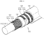
- FIG. 1 is a schematic perspective view of major elements of a cable-type secondary battery combined with a signal wire according to a preferable embodiment of the present disclosure.
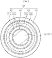
- FIG. 2 is a partial cross-sectional view of FIG. 1 .
- the cable-type secondary battery combined with a signal wire includes a cable-type secondary battery 100 extending in a lengthwise direction and having a hollow interior, a signal wire unit 110 or 110' inserted into the hollow space of the cable-type secondary battery 100, and a cable sheath 104 covering the cable-type secondary battery 100.
- the cable-type secondary battery 100 is a lithium secondary battery extending in a lengthwise direction and includes a hollow anode layer 101, a separator 102 surrounding the anode layer 101, and a cathode layer 103 surrounding the separator 102.
- the anode layer 101, the separator 102, and the cathode layer 103 are spirally wound in the lengthwise direction of the cable-type secondary battery 100.
- each layer is simplified as a circle in FIG. 2 .
- the anode layer 101 is formed as a copper wire 101a coated with a negative electrode active material 101b is spirally wound to extend in the lengthwise direction of the cable.
- a typical negative electrode active material for lithium secondary batteries may be used.
- the separator 102 is formed of a typical separator film for lithium secondary batteries, processed in a ribbon shape.
- the separator 102 is spirally wound around an outer portion of the anode layer 101 and extends in the lengthwise direction of the cable.
- the cathode layer 103 is formed by winding a conductor strip 103a coated with a positive electrode active material 103b around an outer portion of the separator 102 to extend in the lengthwise direction of the cable.
- a typical negative electrode active material for lithium secondary batteries may be used as the positive electrode active material 103b coated on a surface of the conductor strip 103a functioning as a collector.
- the signal wire unit 110 or 110' is disposed to extend in the lengthwise direction of the cable in the anode layer 101 of the cable-type secondary battery 100.
- the signal wire unit 110 or 110' transmits a predetermined optical signal or electrical signal generated in a device to which the cable-type secondary battery is connected, in the cable-type secondary battery 100.
- an internal configuration of the signal wire unit 110 or 110' is omitted in FIGS. 1 and 2 .
- the signal wire unit 110 may be formed of a tight-buffered optical cable having a structure in which each of coated optical fibers 111 is surrounded by a water-proof tight buffer 112 and an outer coating layer 113.
- a double-spiral structure may be formed as each of tight-buffered optical cables extend spirally in a lengthwise direction to be twisted substantially in a spring shape, and different tight-buffered optical cables are extended again spirally with respect to each other so as to be twisted in a spring shape.
- the cable-type secondary battery 100 may be used as a core material in a manufacturing process in which the cable-type secondary battery 100 is assembled by winding the same on an outer portion of the signal wire unit 110. That is, by using the signal wire unit 110 in which optical fibers are twisted in a double-spiral structure, as a winding core, an operational efficiency of the process of spirally winding the anode layer 101, the separator 102, and the cathode layer 103 sequentially in a lengthwise direction of the cable-type secondary battery 100 may be maximized.
- a plurality of tight-buffered optical fibers have a structure of being sequentially surrounded by an inner jacket 114, a metal exterior 115, and an outer jacket 116.
- the signal wire unit 110 may be formed of a loose tube-type optical cable.
- the signal wire unit 110 has a structure in which loose tubes 117 accommodating coated optical fibers 119 are arranged in circles with respect to a central tension line 120, and a jelly 118 is filled in the loose tubes 117 to prevent penetration of moisture.
- the loose tube-type optical cable may preferably be stranded to form an overall double-spiral structure so as to ensure sufficient rigidity.
- the plurality of loose tubes 117 are wound by a binder tape 121, and have a structure in which an inner jacket 122, a metal exterior 123, and an outer jacket 124 are sequentially arranged in an outward direction.
- the signal wire unit 110 may be formed of a slot-type optical cable.
- the signal wire unit 110 includes a structure in which an optical fiber ribbon 126 formed of multi-core coated optical fiber adhered in a ribbon shape is inserted into a slot of a channel structure 125.
- the slot-type optical cable may preferably be disposed to form an overall spiral structure for efficient assembly of the cable-type secondary battery 100 so as to ensure sufficient rigidity.
- a central tension line 127 is disposed in a center of the channel structure 125.
- the channel structure 125 is wound by the binder tape 121, and has a structure in which the inner jacket 122, the metal exterior 123, and the outer jacket 124 are sequentially arranged in an outward direction.
- FIG. 6 illustrates an embodiment in which a signal wire unit 110' is formed of a conductor cable.
- the signal wire unit 110' includes a conducting wire 130 formed of a coated conductor 128 covered by an insulator 129.
- a plurality of conducting wires 130 may be included and wound by a binder tape 131, and surrounded by an outer jacket 132.
- the outer jackets 116, 124, and 132 included in the signal wire units 110 or 110' may be in contact with the anode layer 101 of the cable-type secondary battery 100, and thus may preferably have a surface structure whereby damage to a negative electrode active material layer coated on the anode layer 101 may be minimized.
- a cable sheath 104 is provided in an outermost portion of the cable so as to provide a packaging function and protect the cable-type secondary battery 100 and the signal wire unit 110 or 110' from physical and chemical stress at the same time.
- the cable sheath 104 may be formed of, for example, a polyvinyl chloride (PVC) material.
- the cable-type secondary battery combined with a signal wire is manufactured by preparing the cable-type secondary battery 100 by sequentially stranding an electrode wire for an anode, a separation layer ribbon, and an electrode strip for a cathode on a predetermined winding core in a spiral shape, and inserting the signal wire unit 110 or 110' into empty space formed in a center of the cable-type secondary battery 100 to extend in a lengthwise direction.
- the cable-type secondary battery 100 is used to supply power to a predetermined electronic device connected to the anode layer 101 and the cathode layer 103.
- the signal wire unit 110 or 110' is formed of an optical cable or a conductor cable and transmit an optical signal or an electrical signal generated in the electronic device to a target device in the lengthwise direction of the cable-type secondary battery 100.
- a power supplying function and a signal transmission and reception function may be simultaneously performed using substantially a single cable.
- the cable-type secondary battery combined with a signal wire is usefully applicable to a power storage system such as an uninterruptible power supply (UPS), in which an optical communication network and a secondary battery are integrated, and also to cable-type devices such as earphones, which are connected to portable electronic devices.
- UPS uninterruptible power supply
Landscapes
- Chemical & Material Sciences (AREA)
- Chemical Kinetics & Catalysis (AREA)
- Electrochemistry (AREA)
- General Chemical & Material Sciences (AREA)
- Engineering & Computer Science (AREA)
- Manufacturing & Machinery (AREA)
- Materials Engineering (AREA)
- Secondary Cells (AREA)
- Cell Electrode Carriers And Collectors (AREA)
- Communication Cables (AREA)
- Battery Mounting, Suspending (AREA)
- Battery Electrode And Active Subsutance (AREA)
- Insulated Conductors (AREA)
- Physics & Mathematics (AREA)
- General Physics & Mathematics (AREA)
- Optics & Photonics (AREA)
Abstract
Description
- The present application claims priority to Korean Patent Application No.
10-2016-0015150 filed on February 5, 2016 - The present disclosure relates to a cable-type secondary battery combined with a signal wire, and more particularly, to a cable-type secondary battery combined with a signal wire, in which a signal wire and a cable-type secondary battery are integrated.
- Lithium secondary batteries have many advantages such as a high energy density, a high operating voltage, and excellent storage and lifetime characteristics, and thus are widely used in various portable electronic devices such as personal computers, camcorders, portable telephones, portable compact disc (CD) players, personal digital assistants (PDAs).
- A lithium secondary battery typically includes a cylindrical or prismatic case and an electrode assembly accommodated in the case together with an electrolyte. The electrode assembly is formed by stacking a positive electrode, a separator, and a negative electrode, and has a winding structure or a stack structure in a jelly-roll form.
- Recently, cable-type secondary batteries which have an easily deformable shape and are thus applicable to various fields have been introduced. A cable-type secondary battery is a cell having a very large length-to-diameter ratio, and includes a hollow anode layer, a separator surrounding the anode layer, and a cathode layer surrounding the separator.
- The technology related to cable-type secondary batteries is disclosed in Korean Patent Publication No.
2013-0040160 - Korean Patent Publication No.
2013-0040160 - When a signal wire having a signal transmission function is integrated with the cable-type secondary battery as described above, a cable capable of integrally performing the functions of power supply and signal transmission/reception may be realized. A related technique is disclosed in Korean Patent Publication No.
2001-110244 - Korean Patent Publication No.
2001-110244 - However, regarding such a cable structure as described above, it is difficult to assemble a cable-type secondary battery and a signal cable into a single exterior material, and thus the assembling process and mass production thereof are difficult, requiring a measure to address these difficulties. In addition, due to the structure in which a signal cable is arranged outside the cable-type secondary battery at a predetermined distance, a disadvantage that the total outer diameter is increased is generated.
- The present disclosure is designed to solve the problems of the related art, and therefore the present disclosure is directed to providing an apparatus for manufacturing a cable-type secondary battery having a structure in which signal wires are aggregated so as to simplify an assembling process.
- Another object of the present disclosure is to provide an apparatus for manufacturing a cable-type secondary battery having a structure in which a signal wire is disposed inside the cable-type secondary battery so as to prevent an increase in an outer diameter of the cable.
- These and other objects and advantages of the present disclosure may be understood from the following detailed description and will become more fully apparent from the exemplary embodiments of the present disclosure. Also, it will be easily understood that the objects and advantages of the present disclosure may be realized by the means shown in the appended claims and combinations thereof.
- In one aspect of the present disclosure, there is provided a cable-type secondary battery combined with a signal wire, including: a cable-type secondary battery extending in a lengthwise direction and having a hollow interior; a signal wire unit inserted into the cable-type secondary battery and extending in the lengthwise direction of the cable; and a cable sheath covering the cable-type secondary battery.
- The signal wire unit may preferably be formed of an optical cable.
- The optical cable may be a tight-buffered optical cable, a loose tube-type optical cable, or a slot-type optical cable.
- The signal wire unit may be formed of a conductor cable.
- The cable-type secondary battery may include: a hollow anode layer; a separator surrounding the anode layer; and a cathode layer surrounding the separator.
- The anode layer may be formed by spirally winding a copper wire coated with a negative electrode active material so as to extend in the lengthwise direction of the cable.
- The cathode layer may be formed by spirally winding a conductor strip coated with a positive electrode active material so as to extend in the lengthwise direction of the cable.
- The cable-type secondary battery may be a lithium secondary battery.
- The cable-type secondary battery combined with a signal wire according to the present disclosure gives the following effects.
- First, the assembly process of the cable-type secondary battery combined with a signal wire may be simplified. Accordingly, an automated system may be easily established to enhance productivity of the cable-type secondary battery combined with a signal wire.
- Second, as a signal wire unit is integrated by using empty inner space of the cable-type secondary battery, no additional space for installing the signal wire unit is required, and the increase in the total outer diameter of the cable may be prevented.
- Third, as the signal wire unit which corresponds to an optical cable or a conductor cable is disposed in a center of the cable, the optical cable or the conductor cable may be effectively protected from signal interference or moisture.
- The accompanying drawings illustrate a preferred embodiment of the present disclosure and together with the foregoing disclosure, serve to provide further understanding of the technical features of the present disclosure, and thus, the present disclosure is not construed as being limited to the drawing:
-
FIG. 1 is a schematic perspective view illustrating major elements of a cable-type secondary battery combined with a signal wire according to a preferred embodiment of the present disclosure; -
FIG. 2 is a partial cross-sectional view ofFIG. 1 ; -
FIGS. 3 through 5 are cross-sectional views of a structure of an optical cable that may be used as a signal wire unit inFIG. 2 ; and -
FIG. 6 is a cross-sectional view of a structure of a conductor cable that may be used as a signal wire unit inFIG. 2 . -
FIG. 1 is a schematic perspective view of major elements of a cable-type secondary battery combined with a signal wire according to a preferable embodiment of the present disclosure.FIG. 2 is a partial cross-sectional view ofFIG. 1 . - Referring to
FIGS. 1 and2 , the cable-type secondary battery combined with a signal wire according to the preferable embodiment of the present disclosure includes a cable-typesecondary battery 100 extending in a lengthwise direction and having a hollow interior, asignal wire unit 110 or 110' inserted into the hollow space of the cable-typesecondary battery 100, and acable sheath 104 covering the cable-typesecondary battery 100. - The cable-type
secondary battery 100 is a lithium secondary battery extending in a lengthwise direction and includes ahollow anode layer 101, aseparator 102 surrounding theanode layer 101, and acathode layer 103 surrounding theseparator 102. Theanode layer 101, theseparator 102, and thecathode layer 103 are spirally wound in the lengthwise direction of the cable-typesecondary battery 100. For better understanding, each layer is simplified as a circle inFIG. 2 . - The
anode layer 101 is formed as acopper wire 101a coated with a negative electrodeactive material 101b is spirally wound to extend in the lengthwise direction of the cable. As the negative electrodeactive material 101b that is coated on a surface of thecopper wire 101a and functions as a collector, a typical negative electrode active material for lithium secondary batteries may be used. - The
separator 102 is formed of a typical separator film for lithium secondary batteries, processed in a ribbon shape. Theseparator 102 is spirally wound around an outer portion of theanode layer 101 and extends in the lengthwise direction of the cable. - The
cathode layer 103 is formed by winding aconductor strip 103a coated with a positive electrodeactive material 103b around an outer portion of theseparator 102 to extend in the lengthwise direction of the cable. As the positive electrodeactive material 103b coated on a surface of theconductor strip 103a functioning as a collector, a typical negative electrode active material for lithium secondary batteries may be used. - The
signal wire unit 110 or 110' is disposed to extend in the lengthwise direction of the cable in theanode layer 101 of the cable-typesecondary battery 100. Thesignal wire unit 110 or 110' transmits a predetermined optical signal or electrical signal generated in a device to which the cable-type secondary battery is connected, in the cable-typesecondary battery 100. For convenience of description, an internal configuration of thesignal wire unit 110 or 110' is omitted inFIGS. 1 and2 . - As illustrated in
FIG. 3 , thesignal wire unit 110 may be formed of a tight-buffered optical cable having a structure in which each of coatedoptical fibers 111 is surrounded by a water-prooftight buffer 112 and anouter coating layer 113. Preferably, a double-spiral structure may be formed as each of tight-buffered optical cables extend spirally in a lengthwise direction to be twisted substantially in a spring shape, and different tight-buffered optical cables are extended again spirally with respect to each other so as to be twisted in a spring shape. According to this stranded structure of the double-spiral shape, even when thesignal wire unit 110 is formed of flexible optical fibers, a sufficient overall rigidity may be ensured so that the cable-typesecondary battery 100 may be used as a core material in a manufacturing process in which the cable-typesecondary battery 100 is assembled by winding the same on an outer portion of thesignal wire unit 110. That is, by using thesignal wire unit 110 in which optical fibers are twisted in a double-spiral structure, as a winding core, an operational efficiency of the process of spirally winding theanode layer 101, theseparator 102, and thecathode layer 103 sequentially in a lengthwise direction of the cable-typesecondary battery 100 may be maximized. - A plurality of tight-buffered optical fibers have a structure of being sequentially surrounded by an
inner jacket 114, ametal exterior 115, and anouter jacket 116. - As illustrated in
FIG. 4 , thesignal wire unit 110 may be formed of a loose tube-type optical cable. In this case, thesignal wire unit 110 has a structure in whichloose tubes 117 accommodating coatedoptical fibers 119 are arranged in circles with respect to acentral tension line 120, and ajelly 118 is filled in theloose tubes 117 to prevent penetration of moisture. As described above, for an efficient assembly of the cable-typesecondary battery 100, the loose tube-type optical cable may preferably be stranded to form an overall double-spiral structure so as to ensure sufficient rigidity. - The plurality of
loose tubes 117 are wound by abinder tape 121, and have a structure in which aninner jacket 122, ametal exterior 123, and anouter jacket 124 are sequentially arranged in an outward direction. - As illustrated in
FIG. 5 , thesignal wire unit 110 may be formed of a slot-type optical cable. In this case, thesignal wire unit 110 includes a structure in which anoptical fiber ribbon 126 formed of multi-core coated optical fiber adhered in a ribbon shape is inserted into a slot of achannel structure 125. As described above, the slot-type optical cable may preferably be disposed to form an overall spiral structure for efficient assembly of the cable-typesecondary battery 100 so as to ensure sufficient rigidity. - A
central tension line 127 is disposed in a center of thechannel structure 125. In addition, thechannel structure 125 is wound by thebinder tape 121, and has a structure in which theinner jacket 122, themetal exterior 123, and theouter jacket 124 are sequentially arranged in an outward direction. -
FIG. 6 illustrates an embodiment in which a signal wire unit 110' is formed of a conductor cable. As shown in the drawing, the signal wire unit 110' includes aconducting wire 130 formed of acoated conductor 128 covered by aninsulator 129. In addition, preferably, a plurality of conductingwires 130 may be included and wound by abinder tape 131, and surrounded by anouter jacket 132. - The
outer jackets signal wire units 110 or 110' may be in contact with theanode layer 101 of the cable-typesecondary battery 100, and thus may preferably have a surface structure whereby damage to a negative electrode active material layer coated on theanode layer 101 may be minimized. Acable sheath 104 is provided in an outermost portion of the cable so as to provide a packaging function and protect the cable-typesecondary battery 100 and thesignal wire unit 110 or 110' from physical and chemical stress at the same time. Thecable sheath 104 may be formed of, for example, a polyvinyl chloride (PVC) material. - The cable-type secondary battery combined with a signal wire according to the preferable embodiment of the present disclosure having the above-described structure is manufactured by preparing the cable-type
secondary battery 100 by sequentially stranding an electrode wire for an anode, a separation layer ribbon, and an electrode strip for a cathode on a predetermined winding core in a spiral shape, and inserting thesignal wire unit 110 or 110' into empty space formed in a center of the cable-typesecondary battery 100 to extend in a lengthwise direction. - The cable-type
secondary battery 100 is used to supply power to a predetermined electronic device connected to theanode layer 101 and thecathode layer 103. - The
signal wire unit 110 or 110' is formed of an optical cable or a conductor cable and transmit an optical signal or an electrical signal generated in the electronic device to a target device in the lengthwise direction of the cable-typesecondary battery 100. - Accordingly, according to the present disclosure, a power supplying function and a signal transmission and reception function may be simultaneously performed using substantially a single cable.
- The cable-type secondary battery combined with a signal wire according to the present disclosure is usefully applicable to a power storage system such as an uninterruptible power supply (UPS), in which an optical communication network and a secondary battery are integrated, and also to cable-type devices such as earphones, which are connected to portable electronic devices.
Claims (8)
- A cable-type secondary battery combined with a signal wire, comprising:a cable-type secondary battery extending in a lengthwise direction and having a hollow interior structure;a signal wire unit inserted into the cable-type secondary battery and extending in the lengthwise direction of a cable; anda cable sheath covering an outside of the cable-type secondary battery.
- The cable-type secondary battery combined with a signal wire of claim 1, wherein the signal wire unit is formed of an optical cable.
- The cable-type secondary battery combined with a signal wire of claim 2, wherein the optical cable is a tight-buffered optical cable, a loose tube-type optical cable, or a slot-type optical cable.
- The cable-type secondary battery combined with a signal wire of claim 2, wherein the signal wire unit is formed of a conductor cable.
- The cable-type secondary battery combined with a signal wire of claim 1, wherein the cable-type secondary battery comprises:a hollow anode layer;a separator surrounding the anode layer; anda cathode layer surrounding the separator.
- The cable-type secondary battery combined with a signal wire of claim 5, wherein the anode layer is formed by spirally winding a copper wire coated with a negative electrode active material so as to extend in the lengthwise direction of the cable.
- The cable-type secondary battery combined with a signal wire of claim 5, wherein the cathode layer is formed by spirally winding a conductor strip coated with a positive electrode active material so as to extend in the lengthwise direction of the cable.
- The cable-type secondary battery combined with a signal wire of any one of claims 1 through 7, wherein the cable-type secondary battery is a lithium secondary battery.
Applications Claiming Priority (2)
| Application Number | Priority Date | Filing Date | Title |
|---|---|---|---|
| KR20160015150 | 2016-02-05 | ||
| PCT/KR2017/001304 WO2017135798A1 (en) | 2016-02-05 | 2017-02-06 | Cable-type secondary battery combined with signal wire |
Publications (3)
| Publication Number | Publication Date |
|---|---|
| EP3352284A1 true EP3352284A1 (en) | 2018-07-25 |
| EP3352284A4 EP3352284A4 (en) | 2018-09-26 |
| EP3352284B1 EP3352284B1 (en) | 2019-09-04 |
Family
ID=59500359
Family Applications (1)
| Application Number | Title | Priority Date | Filing Date |
|---|---|---|---|
| EP17747841.9A Active EP3352284B1 (en) | 2016-02-05 | 2017-02-06 | Cable-type secondary battery combined with signal wire |
Country Status (6)
| Country | Link |
|---|---|
| US (1) | US20180287191A1 (en) |
| EP (1) | EP3352284B1 (en) |
| JP (1) | JP6588650B2 (en) |
| KR (1) | KR102059650B1 (en) |
| CN (1) | CN108140902B (en) |
| WO (1) | WO2017135798A1 (en) |
Families Citing this family (2)
| Publication number | Priority date | Publication date | Assignee | Title |
|---|---|---|---|---|
| EP3575182B1 (en) * | 2018-05-31 | 2021-04-07 | Volkswagen AG | Heatable touch sensor and steering wheel comprising such a touch sensor |
| KR102367368B1 (en) * | 2018-07-13 | 2022-02-23 | 주식회사 엘지에너지솔루션 | Data Cable Device Having Cable Battery |
Family Cites Families (10)
| Publication number | Priority date | Publication date | Assignee | Title |
|---|---|---|---|---|
| JP3047778B2 (en) * | 1995-06-14 | 2000-06-05 | 三菱マテリアル株式会社 | Tubular battery |
| JP2001033852A (en) * | 1999-07-19 | 2001-02-09 | Inon:Kk | Light for underwater camera with optical fiber connection and underwater photography system using it |
| JP2001110445A (en) * | 1999-10-12 | 2001-04-20 | Sony Corp | Cord type battery |
| JP2001110244A (en) * | 1999-10-12 | 2001-04-20 | Sony Corp | Battery cable |
| US7088893B2 (en) * | 2003-11-26 | 2006-08-08 | Corning Cable Systems Llc | Pre-connectorized fiber optic distribution cable having multifiber connector |
| CN103314415B (en) * | 2010-11-29 | 2016-08-10 | 普睿司曼股份公司 | Method for measuring the length of a cable using an optical fiber element as a sensor |
| CN103814471A (en) * | 2011-09-19 | 2014-05-21 | 株式会社Lg化学 | Cable type secondary battery |
| BR112014017443B8 (en) * | 2013-05-07 | 2023-03-21 | Lg Chemical Ltd | CABLE TYPE SECONDARY BATTERY |
| EP3518461B1 (en) * | 2013-09-19 | 2022-03-02 | Radius Universal, A Limited Liability Company of the State of New York | Fiber optic communications network |
| JP6270648B2 (en) * | 2014-07-15 | 2018-01-31 | 住友電気工業株式会社 | Slot rod for optical cable and optical cable |
-
2017
- 2017-02-06 KR KR1020170016446A patent/KR102059650B1/en active Active
- 2017-02-06 WO PCT/KR2017/001304 patent/WO2017135798A1/en not_active Ceased
- 2017-02-06 US US15/765,904 patent/US20180287191A1/en not_active Abandoned
- 2017-02-06 JP JP2018535804A patent/JP6588650B2/en active Active
- 2017-02-06 EP EP17747841.9A patent/EP3352284B1/en active Active
- 2017-02-06 CN CN201780003643.3A patent/CN108140902B/en active Active
Also Published As
| Publication number | Publication date |
|---|---|
| JP6588650B2 (en) | 2019-10-09 |
| US20180287191A1 (en) | 2018-10-04 |
| CN108140902B (en) | 2021-06-04 |
| KR102059650B1 (en) | 2019-12-26 |
| WO2017135798A1 (en) | 2017-08-10 |
| EP3352284B1 (en) | 2019-09-04 |
| KR20170093756A (en) | 2017-08-16 |
| CN108140902A (en) | 2018-06-08 |
| JP2018532245A (en) | 2018-11-01 |
| EP3352284A4 (en) | 2018-09-26 |
Similar Documents
| Publication | Publication Date | Title |
|---|---|---|
| EP2772965B1 (en) | Cathode for secondary battery and secondary battery having same | |
| CN108713273B (en) | Cable Type Secondary Battery | |
| EP2772966B1 (en) | Cathode for secondary battery and secondary battery having same | |
| US8993146B2 (en) | Cable-type secondary battery | |
| KR101483686B1 (en) | Cable-Type Secondary Battery | |
| EP2717351B1 (en) | Negative electrode for a secondary battery and secondary battery having the same | |
| WO2011145882A2 (en) | Cable-type secondary battery having a polymer current collector coated with metal | |
| EP3641045B1 (en) | Cable type battery | |
| EP2760074A2 (en) | Cable-type secondary cell | |
| EP3352284B1 (en) | Cable-type secondary battery combined with signal wire | |
| EP4636894A1 (en) | Electrode tab-free cable-type cell having high flexibility and low resistance | |
| KR20210063129A (en) | Cable type secondary battery | |
| WO2017119799A1 (en) | Apparatus and method for manufacturing cable-type secondary battery, and cable-type secondary battery manufactured according to same |
Legal Events
| Date | Code | Title | Description |
|---|---|---|---|
| STAA | Information on the status of an ep patent application or granted ep patent |
Free format text: STATUS: THE INTERNATIONAL PUBLICATION HAS BEEN MADE |
|
| PUAI | Public reference made under article 153(3) epc to a published international application that has entered the european phase |
Free format text: ORIGINAL CODE: 0009012 |
|
| STAA | Information on the status of an ep patent application or granted ep patent |
Free format text: STATUS: REQUEST FOR EXAMINATION WAS MADE |
|
| 17P | Request for examination filed |
Effective date: 20180420 |
|
| AK | Designated contracting states |
Kind code of ref document: A1 Designated state(s): AL AT BE BG CH CY CZ DE DK EE ES FI FR GB GR HR HU IE IS IT LI LT LU LV MC MK MT NL NO PL PT RO RS SE SI SK SM TR |
|
| AX | Request for extension of the european patent |
Extension state: BA ME |
|
| A4 | Supplementary search report drawn up and despatched |
Effective date: 20180828 |
|
| RIC1 | Information provided on ipc code assigned before grant |
Ipc: H01M 4/13 20100101ALI20180822BHEP Ipc: H01M 10/058 20100101AFI20180822BHEP Ipc: H01B 7/00 20060101ALI20180822BHEP Ipc: H01M 10/052 20100101ALI20180822BHEP Ipc: H01M 4/75 20060101ALI20180822BHEP Ipc: H01B 7/06 20060101ALI20180822BHEP |
|
| GRAP | Despatch of communication of intention to grant a patent |
Free format text: ORIGINAL CODE: EPIDOSNIGR1 |
|
| STAA | Information on the status of an ep patent application or granted ep patent |
Free format text: STATUS: GRANT OF PATENT IS INTENDED |
|
| RIC1 | Information provided on ipc code assigned before grant |
Ipc: H01M 4/75 20060101ALI20190329BHEP Ipc: H01M 10/058 20100101AFI20190329BHEP Ipc: H01M 4/13 20100101ALI20190329BHEP Ipc: H01M 10/052 20100101ALI20190329BHEP |
|
| DAV | Request for validation of the european patent (deleted) | ||
| DAX | Request for extension of the european patent (deleted) | ||
| INTG | Intention to grant announced |
Effective date: 20190502 |
|
| GRAS | Grant fee paid |
Free format text: ORIGINAL CODE: EPIDOSNIGR3 |
|
| GRAA | (expected) grant |
Free format text: ORIGINAL CODE: 0009210 |
|
| STAA | Information on the status of an ep patent application or granted ep patent |
Free format text: STATUS: THE PATENT HAS BEEN GRANTED |
|
| AK | Designated contracting states |
Kind code of ref document: B1 Designated state(s): AL AT BE BG CH CY CZ DE DK EE ES FI FR GB GR HR HU IE IS IT LI LT LU LV MC MK MT NL NO PL PT RO RS SE SI SK SM TR |
|
| REG | Reference to a national code |
Ref country code: GB Ref legal event code: FG4D |
|
| REG | Reference to a national code |
Ref country code: CH Ref legal event code: EP |
|
| REG | Reference to a national code |
Ref country code: AT Ref legal event code: REF Ref document number: 1176664 Country of ref document: AT Kind code of ref document: T Effective date: 20190915 |
|
| REG | Reference to a national code |
Ref country code: DE Ref legal event code: R096 Ref document number: 602017006799 Country of ref document: DE Ref country code: IE Ref legal event code: FG4D |
|
| REG | Reference to a national code |
Ref country code: NL Ref legal event code: MP Effective date: 20190904 |
|
| REG | Reference to a national code |
Ref country code: LT Ref legal event code: MG4D |
|
| PG25 | Lapsed in a contracting state [announced via postgrant information from national office to epo] |
Ref country code: LT Free format text: LAPSE BECAUSE OF FAILURE TO SUBMIT A TRANSLATION OF THE DESCRIPTION OR TO PAY THE FEE WITHIN THE PRESCRIBED TIME-LIMIT Effective date: 20190904 Ref country code: FI Free format text: LAPSE BECAUSE OF FAILURE TO SUBMIT A TRANSLATION OF THE DESCRIPTION OR TO PAY THE FEE WITHIN THE PRESCRIBED TIME-LIMIT Effective date: 20190904 Ref country code: SE Free format text: LAPSE BECAUSE OF FAILURE TO SUBMIT A TRANSLATION OF THE DESCRIPTION OR TO PAY THE FEE WITHIN THE PRESCRIBED TIME-LIMIT Effective date: 20190904 Ref country code: HR Free format text: LAPSE BECAUSE OF FAILURE TO SUBMIT A TRANSLATION OF THE DESCRIPTION OR TO PAY THE FEE WITHIN THE PRESCRIBED TIME-LIMIT Effective date: 20190904 Ref country code: NO Free format text: LAPSE BECAUSE OF FAILURE TO SUBMIT A TRANSLATION OF THE DESCRIPTION OR TO PAY THE FEE WITHIN THE PRESCRIBED TIME-LIMIT Effective date: 20191204 Ref country code: BG Free format text: LAPSE BECAUSE OF FAILURE TO SUBMIT A TRANSLATION OF THE DESCRIPTION OR TO PAY THE FEE WITHIN THE PRESCRIBED TIME-LIMIT Effective date: 20191204 |
|
| PG25 | Lapsed in a contracting state [announced via postgrant information from national office to epo] |
Ref country code: LV Free format text: LAPSE BECAUSE OF FAILURE TO SUBMIT A TRANSLATION OF THE DESCRIPTION OR TO PAY THE FEE WITHIN THE PRESCRIBED TIME-LIMIT Effective date: 20190904 Ref country code: ES Free format text: LAPSE BECAUSE OF FAILURE TO SUBMIT A TRANSLATION OF THE DESCRIPTION OR TO PAY THE FEE WITHIN THE PRESCRIBED TIME-LIMIT Effective date: 20190904 Ref country code: AL Free format text: LAPSE BECAUSE OF FAILURE TO SUBMIT A TRANSLATION OF THE DESCRIPTION OR TO PAY THE FEE WITHIN THE PRESCRIBED TIME-LIMIT Effective date: 20190904 Ref country code: GR Free format text: LAPSE BECAUSE OF FAILURE TO SUBMIT A TRANSLATION OF THE DESCRIPTION OR TO PAY THE FEE WITHIN THE PRESCRIBED TIME-LIMIT Effective date: 20191205 Ref country code: RS Free format text: LAPSE BECAUSE OF FAILURE TO SUBMIT A TRANSLATION OF THE DESCRIPTION OR TO PAY THE FEE WITHIN THE PRESCRIBED TIME-LIMIT Effective date: 20190904 |
|
| REG | Reference to a national code |
Ref country code: AT Ref legal event code: MK05 Ref document number: 1176664 Country of ref document: AT Kind code of ref document: T Effective date: 20190904 |
|
| PG25 | Lapsed in a contracting state [announced via postgrant information from national office to epo] |
Ref country code: AT Free format text: LAPSE BECAUSE OF FAILURE TO SUBMIT A TRANSLATION OF THE DESCRIPTION OR TO PAY THE FEE WITHIN THE PRESCRIBED TIME-LIMIT Effective date: 20190904 Ref country code: PL Free format text: LAPSE BECAUSE OF FAILURE TO SUBMIT A TRANSLATION OF THE DESCRIPTION OR TO PAY THE FEE WITHIN THE PRESCRIBED TIME-LIMIT Effective date: 20190904 Ref country code: EE Free format text: LAPSE BECAUSE OF FAILURE TO SUBMIT A TRANSLATION OF THE DESCRIPTION OR TO PAY THE FEE WITHIN THE PRESCRIBED TIME-LIMIT Effective date: 20190904 Ref country code: PT Free format text: LAPSE BECAUSE OF FAILURE TO SUBMIT A TRANSLATION OF THE DESCRIPTION OR TO PAY THE FEE WITHIN THE PRESCRIBED TIME-LIMIT Effective date: 20200106 Ref country code: RO Free format text: LAPSE BECAUSE OF FAILURE TO SUBMIT A TRANSLATION OF THE DESCRIPTION OR TO PAY THE FEE WITHIN THE PRESCRIBED TIME-LIMIT Effective date: 20190904 Ref country code: NL Free format text: LAPSE BECAUSE OF FAILURE TO SUBMIT A TRANSLATION OF THE DESCRIPTION OR TO PAY THE FEE WITHIN THE PRESCRIBED TIME-LIMIT Effective date: 20190904 Ref country code: IT Free format text: LAPSE BECAUSE OF FAILURE TO SUBMIT A TRANSLATION OF THE DESCRIPTION OR TO PAY THE FEE WITHIN THE PRESCRIBED TIME-LIMIT Effective date: 20190904 |
|
| PG25 | Lapsed in a contracting state [announced via postgrant information from national office to epo] |
Ref country code: SM Free format text: LAPSE BECAUSE OF FAILURE TO SUBMIT A TRANSLATION OF THE DESCRIPTION OR TO PAY THE FEE WITHIN THE PRESCRIBED TIME-LIMIT Effective date: 20190904 Ref country code: SK Free format text: LAPSE BECAUSE OF FAILURE TO SUBMIT A TRANSLATION OF THE DESCRIPTION OR TO PAY THE FEE WITHIN THE PRESCRIBED TIME-LIMIT Effective date: 20190904 Ref country code: IS Free format text: LAPSE BECAUSE OF FAILURE TO SUBMIT A TRANSLATION OF THE DESCRIPTION OR TO PAY THE FEE WITHIN THE PRESCRIBED TIME-LIMIT Effective date: 20200224 Ref country code: CZ Free format text: LAPSE BECAUSE OF FAILURE TO SUBMIT A TRANSLATION OF THE DESCRIPTION OR TO PAY THE FEE WITHIN THE PRESCRIBED TIME-LIMIT Effective date: 20190904 |
|
| REG | Reference to a national code |
Ref country code: DE Ref legal event code: R097 Ref document number: 602017006799 Country of ref document: DE |
|
| PLBE | No opposition filed within time limit |
Free format text: ORIGINAL CODE: 0009261 |
|
| STAA | Information on the status of an ep patent application or granted ep patent |
Free format text: STATUS: NO OPPOSITION FILED WITHIN TIME LIMIT |
|
| PG2D | Information on lapse in contracting state deleted |
Ref country code: IS |
|
| PG25 | Lapsed in a contracting state [announced via postgrant information from national office to epo] |
Ref country code: DK Free format text: LAPSE BECAUSE OF FAILURE TO SUBMIT A TRANSLATION OF THE DESCRIPTION OR TO PAY THE FEE WITHIN THE PRESCRIBED TIME-LIMIT Effective date: 20190904 Ref country code: IS Free format text: LAPSE BECAUSE OF FAILURE TO SUBMIT A TRANSLATION OF THE DESCRIPTION OR TO PAY THE FEE WITHIN THE PRESCRIBED TIME-LIMIT Effective date: 20200105 |
|
| 26N | No opposition filed |
Effective date: 20200605 |
|
| PG25 | Lapsed in a contracting state [announced via postgrant information from national office to epo] |
Ref country code: SI Free format text: LAPSE BECAUSE OF FAILURE TO SUBMIT A TRANSLATION OF THE DESCRIPTION OR TO PAY THE FEE WITHIN THE PRESCRIBED TIME-LIMIT Effective date: 20190904 |
|
| REG | Reference to a national code |
Ref country code: CH Ref legal event code: PL |
|
| REG | Reference to a national code |
Ref country code: BE Ref legal event code: MM Effective date: 20200229 |
|
| PG25 | Lapsed in a contracting state [announced via postgrant information from national office to epo] |
Ref country code: MC Free format text: LAPSE BECAUSE OF FAILURE TO SUBMIT A TRANSLATION OF THE DESCRIPTION OR TO PAY THE FEE WITHIN THE PRESCRIBED TIME-LIMIT Effective date: 20190904 Ref country code: LU Free format text: LAPSE BECAUSE OF NON-PAYMENT OF DUE FEES Effective date: 20200206 |
|
| PG25 | Lapsed in a contracting state [announced via postgrant information from national office to epo] |
Ref country code: LI Free format text: LAPSE BECAUSE OF NON-PAYMENT OF DUE FEES Effective date: 20200229 Ref country code: CH Free format text: LAPSE BECAUSE OF NON-PAYMENT OF DUE FEES Effective date: 20200229 |
|
| PG25 | Lapsed in a contracting state [announced via postgrant information from national office to epo] |
Ref country code: IE Free format text: LAPSE BECAUSE OF NON-PAYMENT OF DUE FEES Effective date: 20200206 |
|
| PG25 | Lapsed in a contracting state [announced via postgrant information from national office to epo] |
Ref country code: BE Free format text: LAPSE BECAUSE OF NON-PAYMENT OF DUE FEES Effective date: 20200229 |
|
| PG25 | Lapsed in a contracting state [announced via postgrant information from national office to epo] |
Ref country code: TR Free format text: LAPSE BECAUSE OF FAILURE TO SUBMIT A TRANSLATION OF THE DESCRIPTION OR TO PAY THE FEE WITHIN THE PRESCRIBED TIME-LIMIT Effective date: 20190904 Ref country code: MT Free format text: LAPSE BECAUSE OF FAILURE TO SUBMIT A TRANSLATION OF THE DESCRIPTION OR TO PAY THE FEE WITHIN THE PRESCRIBED TIME-LIMIT Effective date: 20190904 Ref country code: CY Free format text: LAPSE BECAUSE OF FAILURE TO SUBMIT A TRANSLATION OF THE DESCRIPTION OR TO PAY THE FEE WITHIN THE PRESCRIBED TIME-LIMIT Effective date: 20190904 |
|
| PG25 | Lapsed in a contracting state [announced via postgrant information from national office to epo] |
Ref country code: MK Free format text: LAPSE BECAUSE OF FAILURE TO SUBMIT A TRANSLATION OF THE DESCRIPTION OR TO PAY THE FEE WITHIN THE PRESCRIBED TIME-LIMIT Effective date: 20190904 |
|
| P01 | Opt-out of the competence of the unified patent court (upc) registered |
Effective date: 20230512 |
|
| REG | Reference to a national code |
Ref country code: DE Ref legal event code: R081 Ref document number: 602017006799 Country of ref document: DE Owner name: LG ENERGY SOLUTION, LTD., KR Free format text: FORMER OWNER: LG CHEM, LTD., SEOUL, KR |
|
| REG | Reference to a national code |
Ref country code: GB Ref legal event code: 732E Free format text: REGISTERED BETWEEN 20230824 AND 20230831 |
|
| PGFP | Annual fee paid to national office [announced via postgrant information from national office to epo] |
Ref country code: GB Payment date: 20260122 Year of fee payment: 10 |
|
| PGFP | Annual fee paid to national office [announced via postgrant information from national office to epo] |
Ref country code: DE Payment date: 20260120 Year of fee payment: 10 |
|
| PGFP | Annual fee paid to national office [announced via postgrant information from national office to epo] |
Ref country code: FR Payment date: 20260121 Year of fee payment: 10 |