EP3352249A1 - Battery cell and method of manufacturing a battery cell - Google Patents
Battery cell and method of manufacturing a battery cell Download PDFInfo
- Publication number
- EP3352249A1 EP3352249A1 EP17152144.6A EP17152144A EP3352249A1 EP 3352249 A1 EP3352249 A1 EP 3352249A1 EP 17152144 A EP17152144 A EP 17152144A EP 3352249 A1 EP3352249 A1 EP 3352249A1
- Authority
- EP
- European Patent Office
- Prior art keywords
- electrode
- assembly
- tabs
- plates
- battery cell
- Prior art date
- Legal status (The legal status is an assumption and is not a legal conclusion. Google has not performed a legal analysis and makes no representation as to the accuracy of the status listed.)
- Granted
Links
Images


Classifications
-
- H—ELECTRICITY
- H01—ELECTRIC ELEMENTS
- H01M—PROCESSES OR MEANS, e.g. BATTERIES, FOR THE DIRECT CONVERSION OF CHEMICAL ENERGY INTO ELECTRICAL ENERGY
- H01M10/00—Secondary cells; Manufacture thereof
- H01M10/05—Accumulators with non-aqueous electrolyte
- H01M10/052—Li-accumulators
- H01M10/0525—Rocking-chair batteries, i.e. batteries with lithium insertion or intercalation in both electrodes; Lithium-ion batteries
-
- H—ELECTRICITY
- H01—ELECTRIC ELEMENTS
- H01M—PROCESSES OR MEANS, e.g. BATTERIES, FOR THE DIRECT CONVERSION OF CHEMICAL ENERGY INTO ELECTRICAL ENERGY
- H01M50/00—Constructional details or processes of manufacture of the non-active parts of electrochemical cells other than fuel cells, e.g. hybrid cells
- H01M50/10—Primary casings; Jackets or wrappings
- H01M50/102—Primary casings; Jackets or wrappings characterised by their shape or physical structure
- H01M50/103—Primary casings; Jackets or wrappings characterised by their shape or physical structure prismatic or rectangular
-
- H—ELECTRICITY
- H01—ELECTRIC ELEMENTS
- H01M—PROCESSES OR MEANS, e.g. BATTERIES, FOR THE DIRECT CONVERSION OF CHEMICAL ENERGY INTO ELECTRICAL ENERGY
- H01M50/00—Constructional details or processes of manufacture of the non-active parts of electrochemical cells other than fuel cells, e.g. hybrid cells
- H01M50/50—Current conducting connections for cells or batteries
- H01M50/531—Electrode connections inside a battery casing
- H01M50/538—Connection of several leads or tabs of wound or folded electrode stacks
-
- H—ELECTRICITY
- H01—ELECTRIC ELEMENTS
- H01M—PROCESSES OR MEANS, e.g. BATTERIES, FOR THE DIRECT CONVERSION OF CHEMICAL ENERGY INTO ELECTRICAL ENERGY
- H01M50/00—Constructional details or processes of manufacture of the non-active parts of electrochemical cells other than fuel cells, e.g. hybrid cells
- H01M50/50—Current conducting connections for cells or batteries
- H01M50/531—Electrode connections inside a battery casing
- H01M50/54—Connection of several leads or tabs of plate-like electrode stacks, e.g. electrode pole straps or bridges
-
- Y—GENERAL TAGGING OF NEW TECHNOLOGICAL DEVELOPMENTS; GENERAL TAGGING OF CROSS-SECTIONAL TECHNOLOGIES SPANNING OVER SEVERAL SECTIONS OF THE IPC; TECHNICAL SUBJECTS COVERED BY FORMER USPC CROSS-REFERENCE ART COLLECTIONS [XRACs] AND DIGESTS
- Y02—TECHNOLOGIES OR APPLICATIONS FOR MITIGATION OR ADAPTATION AGAINST CLIMATE CHANGE
- Y02E—REDUCTION OF GREENHOUSE GAS [GHG] EMISSIONS, RELATED TO ENERGY GENERATION, TRANSMISSION OR DISTRIBUTION
- Y02E60/00—Enabling technologies; Technologies with a potential or indirect contribution to GHG emissions mitigation
- Y02E60/10—Energy storage using batteries
-
- Y—GENERAL TAGGING OF NEW TECHNOLOGICAL DEVELOPMENTS; GENERAL TAGGING OF CROSS-SECTIONAL TECHNOLOGIES SPANNING OVER SEVERAL SECTIONS OF THE IPC; TECHNICAL SUBJECTS COVERED BY FORMER USPC CROSS-REFERENCE ART COLLECTIONS [XRACs] AND DIGESTS
- Y02—TECHNOLOGIES OR APPLICATIONS FOR MITIGATION OR ADAPTATION AGAINST CLIMATE CHANGE
- Y02P—CLIMATE CHANGE MITIGATION TECHNOLOGIES IN THE PRODUCTION OR PROCESSING OF GOODS
- Y02P70/00—Climate change mitigation technologies in the production process for final industrial or consumer products
- Y02P70/50—Manufacturing or production processes characterised by the final manufactured product
Definitions
- the invention relates to a battery cell and to a method of manufacturing a battery cell.
- battery and “battery cell” are used. These expressions are understood to encompass primary cells as well as secondary cells, i.e. accumulator cells.
- a battery typically comprises a set of battery cells electronically linked to each other.
- Jelly rolls or stacked battery cells of the lithium ion type typically consist of cathode electrode material on an aluminum foil (positive electrode), anode electrode material on a copper foil (negative electrode) and a separator soaked in electrolyte.
- the jelly roll is made by rolling these elements together.
- the stacked battery cell is created by stacking these elements in layers on one another.
- the current collector tabs of the jelly rolls or stacks, hereinafter also called electrode tabs, are then connected with terminals and the complete assembly is sealed hermetically in aluminum or steel cans.
- the lithium ions are migrating from the cathode by dint of electrolyte across the separator to the anode simultaneously with an electron flow in the same direction on the external circuit. During discharge, these processes are taking place in the opposite direction.
- US 2015/0364727 shows a rechargeable battery including a plurality of electrode assemblies arranged in a case.
- the electrode tabs are welded to a bottom surface of a flange of a terminal connected to the cap assembly.
- the electrode tabs are bent at least once in a direction parallel to the first and second electrode plates.
- US 2007/0105015 discloses a U-shaped electrode lead via which a terminal for a battery cover is connected to an electrode of a power-generating element.
- the electrode lead is bent twice in a direction parallel to the first and second electrode plates.
- the present invention proposes a battery cell, in particular a prismatic lithium ion cell, the battery cell comprising an electrode assembly, a battery case for housing the electrode assembly and a cap assembly for closing the battery case, the cap assembly comprising a set of terminals arranged thereon.
- the electrode assembly comprises first electrode plates, separator plates and second electrode plates stacked on one another. Electrode tabs are provided to electrically connect the electrode assembly with the terminals. The electrode tabs are bent at least once in a direction normal to the first and second electrode plates.
- the term "normal to the first and second electrode plates” is understood as follows:
- the electrodes are essentially plate-like and typically consist of active material on metal foils.
- the cathode electrode material may be coated on an aluminum foil, and the anode electrode material may be coated on a copper foil.
- the plates are stacked on one another such that they are arranged in parallel. The direction perpendicular to the plates is the normal direction.
- the electrode tabs being bent in the direction normal to the first and second electrode plates means that the folding line is perpendicular to the plane of the electrode plates.
- the electrode assembly comprises a first and a second electrode step. Two stacks are considered to minimize the scrap rate in the production line. The stacks are stacked on one another.
- the electrode tabs of the first stack are first folded onto the electrode tabs of the second stack and then bent at least once in the direction normal to the first and second electrode plates. Once folded, the area of the folds is more compact. Furthermore, the electrode tabs of the electrodes being folded on one another, allows for a lesser number of tabs to be connected with the terminals. Furthermore, a lesser number of tabs to be connected with the terminals leads to a higher welding efficiency
- the electrode tabs are directly connected to the terminals.
- an additional connection part e.g. connection part 7 in US 2007/0105015 .
- the specific folded arrangement results in a lowering of the height of the folded area because welding of the electrode tabs to the additional connection part is not required. Therefore, for a fixed total height of the battery cell, the relative height of the electrode assembly can be increased.
- At least one isolating member is arranged on the electrode tabs.
- the isolating member can be arranged on the electrode tabs of the first stack folded on the electrode tabs of the second stack.
- the electrode tabs are provided at the corner of the electrode assembly.
- An advantage of this embodiment is that the terminals of the cap assembly can also be arranged more closely to the edge of the cap assembly such that the elements from the center of the cap assembly, in particular the bursting membrane, may be designed more freely, e.g. the bursting membrane can be designed larger.
- the invention provides a method of manufacturing a battery cell, in particular a prismatic lithium ion cell, the method comprising a step of providing an electrode assembly, where the electrode assembly comprises first electrode plates, separator plates and second electrode plates stacked on one another, the electrode plates being provided with electrode tabs for the external electric connection of the electrode assembly, a step of bending the electrode tabs at least once in a direction normal to the first and second electrode plates, a step of providing a cap assembly for closing the battery case, the cap assembly comprising a set of terminals arranged thereon, a step of electrically connecting the electrode tabs with the terminals, a step of providing a battery case for housing the electrode assembly, a step of housing the electrode assembly in the battery case, and a step of closing the battery case with the cap assembly.
- the method of manufacturing the battery cell may be finished by the steps of filling the battery case with a liquid electrolyte and by sealing the battery case hermetically.
- An advantage of using the cap plate fixation according to the present invention is that a rotating process of the cap plate can be avoided.
- the invention allows for a vertical positioning of the cap plate relative to the stack.
- the electrode assembly comprises a first and a second stack.
- the method may then further comprise a step of folding the electrode tabs of the first stack onto the electrode tabs of the second stack, the step being followed by the step of bending the electrode tabs at least once in the direction normal to the first and second electrode plates.
- the electrode tabs extend over the edges of the electrode assembly before being bent at least once in the direction normal to the first and second electrode plates. Since free-standing protruding electrode tabs can be easily handled by machines, this allows for easy manufacture.
- the electrode tabs extend towards the center of the electrode assembly before being bent at least once in the direction normal to the first and second electrode plates.
- the step of electrically connecting the electrode tabs with the terminals comprises laser welding, ultrasound welding or clinching technology.
- the invention allows for an increased active area of electrodes as well as of a reduction of dead volume and, consequently, an increase in the overall energy density of the battery cell.
- the invention allows for a cheap and less complicated method of manufacturing such a battery cell.
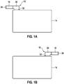
- Figure 1A shows a side view of a first electrode plate 14 having an electrode tab 12 according to an embodiment of the invention.
- the first electrode plate 14, e.g. the anode has a rectangular shape with sides a and b.
- the sides a and b can be of equal length.
- the electrode tab 12 is arranged in the corner of the first electrode plate 14. In the depicted embodiment, the electrode tab 12 is arranged close to the edge of the longer side a and protrudes therefrom.
- Electrode tab 12 comprises a socket portion 22, a protruding portion 20, a bending portion 18 and a connecting portion 30.
- the protruding portion 20 defines the intermediate portion between the socket portion 22 and the bending portion 18.
- the bending portion 18 and connecting portion 30 are at a right angle to the socket portion 22.
- the connecting portion 30 is at the tip of the bending portion 18. Its function will be explained more in detail with regard to Figure 4d .
- FIG 1B shows a side view of a second electrode plate 16 having an electrode tab 12 according to a first embodiment of the invention.
- the second electrode plate 16 e.g. the cathode, has a rectangular shape with sides a and b. The sides a and b can be of equal length.
- the electrode tab 12 also comprises the socket portion 22, the protruding portion 20 and the bending portion 18 with the connecting portions 30 as the tip of the electrode tab 12, as described with regards to Figure 1A .
- the electrode tab 12 of the second electrode plate 16 is arranged opposed to the respective electrode tab 12 of the first electrode plate 14 of Figure 1A . In both electrode plates 14, 16 the bending portion 18 extends over the edge of the side a.
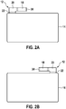
- Figures 2A and 2B show first and second electrode plates 14, 16 according to an alternative embodiment of the invention.
- the bending portion 18 and connecting portions 30 extend towards the center of the electrode plates 14 and 16, respectively.
- Figures 3A to 3E show steps of manufacturing a battery cell 2.
- FIG 3A shows a perspective view of an electrode assembly 4 according to an embodiment of the invention at a first step of a manufacturing process.
- the electrode assembly 4 comprises a first stack 24 and a second stack 26 stacked on top of each other (from a layer perspective).
- the four electrode tabs 12 are folded inwards towards each other such that the electrode tabs 12 of the first stack 24 are folded onto the electrode tabs 12 of the second stack 26.
- the electrode tabs 12 of the second stack 26 are first folded down in the direction to the first stack 24. The result of this step is shown in Figure 3B .
- the electrode tabs 12 of the first stack 24 are folded onto the electrode tabs 12 of the second stack 26. The result of the step is shown in Figure 3C .
- an isolating member 28 is arranged on the folded electrode tabs 12.
- the isolating member 28 may essentially cover the whole top surface of the electrode assembly 4.
- Figure 3D shows the electrode assembly 4 after bending the four electrode tabs 12 upwardly, i.e. in a direction normal to the first and second electrode plates 14, 16.
- the connecting portions 30 are now bent such that they extend parallel to the top surface of the electrode assembly 4.
- FIG 3E shows battery cell 2 comprising the battery case 6 and the cap assembly 8.
- the electrode assembly 4 (not depicted) is arranged in the battery case 6.
- the cap assembly 8 is positioned onto the electrode assembly 4.
- the cap assembly 8 comprises positive and negative terminals 10 which are positioned close to the edge of the cap assembly 8 and opposed to each other. In the center of the cap assembly 8, a bursting membrane 32 is provided. Due to the extremal positioning of the terminals 10, the bursting membrane 32 can be freely designed, in particular regarding its form and position on the cap assembly 8.
- the cap assembly 8 further comprises a fill-in opening 34 for the liquid electrolyte.
- the method of manufacturing the battery cell 2 may comprise the step of electrically connecting the electrode tabs 12 with the terminals 10 first and then housing the electrode assembly 4 (not depicted) in the battery case 6, or the steps being in the other order.
- the assembly steps may be followed by the step of filling the battery case 6 with a liquid electrolyte and by the step of sealing the battery case 6, e.g. by welding the battery case to the cap assembly 8.
- Figure 4A shows a side view of an arrangement of a section of the cap assembly 8 and a corner section of the electrode assembly 4 according to an embodiment of the invention at a first step of its assembling process.
- the bending portion 18 comprises a folding line 36, which is normal to the first and second electrode plates 14, 16.
- the connecting portion 30 is connected with a respective connecting element 38 of the cap assembly 8, thereby providing the electrical connection to the terminal 10.
- Figure 4B shows a side view of an arrangement of a section of a cap assembly 8 and a corner section of an electrode assembly 4 according to an embodiment of the invention at a second step of its assembling process.
- the cap assembly 8 is closely pressed to the electrode assembly 4 thus reducing the volume between them.
- Figure 5 shows a perspective view of an electrode assembly 4 according to another embodiment of the invention.
- the isolating member 28 is provided in form of two isolation tapes 40 applied on top of the electrode assembly.
- the isolation tapes 40 cover the areas where the electrode tabs 12 have been folded onto each other, e.g. the protruding portions 20.
Landscapes
- Chemical & Material Sciences (AREA)
- Chemical Kinetics & Catalysis (AREA)
- Electrochemistry (AREA)
- General Chemical & Material Sciences (AREA)
- Engineering & Computer Science (AREA)
- Materials Engineering (AREA)
- Manufacturing & Machinery (AREA)
- Connection Of Batteries Or Terminals (AREA)
- Secondary Cells (AREA)
Abstract
Description
- The invention relates to a battery cell and to a method of manufacturing a battery cell.
- In the present disclosure, the terms "battery" and "battery cell" are used. These expressions are understood to encompass primary cells as well as secondary cells, i.e. accumulator cells. A battery typically comprises a set of battery cells electronically linked to each other.
- Jelly rolls or stacked battery cells of the lithium ion type typically consist of cathode electrode material on an aluminum foil (positive electrode), anode electrode material on a copper foil (negative electrode) and a separator soaked in electrolyte. The jelly roll is made by rolling these elements together. The stacked battery cell is created by stacking these elements in layers on one another. The current collector tabs of the jelly rolls or stacks, hereinafter also called electrode tabs, are then connected with terminals and the complete assembly is sealed hermetically in aluminum or steel cans.
- During the charge of lithium ion cells, the lithium ions are migrating from the cathode by dint of electrolyte across the separator to the anode simultaneously with an electron flow in the same direction on the external circuit. During discharge, these processes are taking place in the opposite direction.
-
US 2015/0364727 shows a rechargeable battery including a plurality of electrode assemblies arranged in a case. The electrode tabs are welded to a bottom surface of a flange of a terminal connected to the cap assembly. The electrode tabs are bent at least once in a direction parallel to the first and second electrode plates. -
US 2007/0105015 discloses a U-shaped electrode lead via which a terminal for a battery cover is connected to an electrode of a power-generating element. The electrode lead is bent twice in a direction parallel to the first and second electrode plates. - It is an objective of the present invention to decrease the "dead volume" below the cap plate, i.e. the volume occupied by current-collecting means and the external connection of the electrode assembly.
- It is another objective of the present invention to provide a faster and easier method of manufacturing a battery cell.
- In a first aspect, the present invention proposes a battery cell, in particular a prismatic lithium ion cell, the battery cell comprising an electrode assembly, a battery case for housing the electrode assembly and a cap assembly for closing the battery case, the cap assembly comprising a set of terminals arranged thereon. The electrode assembly comprises first electrode plates, separator plates and second electrode plates stacked on one another. Electrode tabs are provided to electrically connect the electrode assembly with the terminals. The electrode tabs are bent at least once in a direction normal to the first and second electrode plates.
- The term "normal to the first and second electrode plates" is understood as follows: The electrodes are essentially plate-like and typically consist of active material on metal foils. In case of a lithium ion type, the cathode electrode material may be coated on an aluminum foil, and the anode electrode material may be coated on a copper foil. The plates are stacked on one another such that they are arranged in parallel. The direction perpendicular to the plates is the normal direction. The electrode tabs being bent in the direction normal to the first and second electrode plates means that the folding line is perpendicular to the plane of the electrode plates.
- According to an embodiment, the electrode assembly comprises a first and a second electrode step. Two stacks are considered to minimize the scrap rate in the production line. The stacks are stacked on one another.
- According to an embodiment, the electrode tabs of the first stack are first folded onto the electrode tabs of the second stack and then bent at least once in the direction normal to the first and second electrode plates. Once folded, the area of the folds is more compact. Furthermore, the electrode tabs of the electrodes being folded on one another, allows for a lesser number of tabs to be connected with the terminals. Furthermore, a lesser number of tabs to be connected with the terminals leads to a higher welding efficiency
- Preferably, the electrode tabs are directly connected to the terminals. In this embodiment, there is no need for an additional connection part, e.g. connection part 7 in
US 2007/0105015 . The specific folded arrangement results in a lowering of the height of the folded area because welding of the electrode tabs to the additional connection part is not required. Therefore, for a fixed total height of the battery cell, the relative height of the electrode assembly can be increased. - According to an embodiment, at least one isolating member is arranged on the electrode tabs. Particularly, the isolating member can be arranged on the electrode tabs of the first stack folded on the electrode tabs of the second stack.
- According to an embodiment, the electrode tabs are provided at the corner of the electrode assembly. An advantage of this embodiment is that the terminals of the cap assembly can also be arranged more closely to the edge of the cap assembly such that the elements from the center of the cap assembly, in particular the bursting membrane, may be designed more freely, e.g. the bursting membrane can be designed larger.
- In another aspect, the invention provides a method of manufacturing a battery cell, in particular a prismatic lithium ion cell, the method comprising a step of providing an electrode assembly, where the electrode assembly comprises first electrode plates, separator plates and second electrode plates stacked on one another, the electrode plates being provided with electrode tabs for the external electric connection of the electrode assembly, a step of bending the electrode tabs at least once in a direction normal to the first and second electrode plates, a step of providing a cap assembly for closing the battery case, the cap assembly comprising a set of terminals arranged thereon, a step of electrically connecting the electrode tabs with the terminals, a step of providing a battery case for housing the electrode assembly, a step of housing the electrode assembly in the battery case, and a step of closing the battery case with the cap assembly.
- The method of manufacturing the battery cell may be finished by the steps of filling the battery case with a liquid electrolyte and by sealing the battery case hermetically.
- An advantage of using the cap plate fixation according to the present invention is that a rotating process of the cap plate can be avoided. The invention allows for a vertical positioning of the cap plate relative to the stack.
- According to an embodiment, the electrode assembly comprises a first and a second stack. The method may then further comprise a step of folding the electrode tabs of the first stack onto the electrode tabs of the second stack, the step being followed by the step of bending the electrode tabs at least once in the direction normal to the first and second electrode plates.
- According to an embodiment, the electrode tabs extend over the edges of the electrode assembly before being bent at least once in the direction normal to the first and second electrode plates. Since free-standing protruding electrode tabs can be easily handled by machines, this allows for easy manufacture.
- According to an alternative embodiment, the electrode tabs extend towards the center of the electrode assembly before being bent at least once in the direction normal to the first and second electrode plates.
- According to preferred embodiments, the step of electrically connecting the electrode tabs with the terminals comprises laser welding, ultrasound welding or clinching technology.
- The invention allows for an increased active area of electrodes as well as of a reduction of dead volume and, consequently, an increase in the overall energy density of the battery cell.
- Furthermore, the invention allows for a cheap and less complicated method of manufacturing such a battery cell.
- Exemplary embodiments of the invention are depicted in the following figures and will be explained in the following description of the figures.
- Figure 1A
- shows a side view of a first electrode plate having an electrode tab according to a first embodiment of the invention,
- Figure 1B
- shows a side view of a second electrode plate having an electrode tab according to a first embodiment of the invention,
- Figure 2A
- shows a side view of a first electrode plate having an electrode tab according to a second embodiment of the invention,
- Figure 2B
- shows a side view of a second electrode plate having an electrode tab according to a second embodiment of the invention,
- Figure 3A
- shows a perspective view of an electrode assembly according to an embodiment of the invention at a first step of a manufacturing process,
- Figure 3B
- shows a perspective view of an electrode assembly according to an embodiment of the invention at a second step of a manufacturing process,
- Figure 3C
- shows a perspective view of an electrode assembly according to an embodiment of the invention at a third step of a manufacturing process,
- Figure 3D
- shows a perspective view of an electrode assembly according to an embodiment of the invention at a fourth step of a manufacturing process,
- Figure 3E
- shows a perspective view of an battery cell according to an embodiment of the invention at a fifth step of a manufacturing process,
- Figure 4A
- shows a side view of an arrangement of a section of a cap assembly and a corner section of an electrode assembly according to an embodiment of the invention at a first step of its assembling process, and
- Figure 4B
- shows a side view of an arrangement of a section of a cap assembly and a corner section of an electrode assembly according to an embodiment of the invention at a second step of its assembling process,
- Figure 5
- shows a perspective view of an electrode assembly according to another embodiment of the invention.
- In the following description of the figures, same or similar features are provided with same or similar reference signs. In some cases, redundant description of components is avoided, in order to improve the clarity of the description.
-
Figure 1A shows a side view of afirst electrode plate 14 having anelectrode tab 12 according to an embodiment of the invention. Thefirst electrode plate 14, e.g. the anode, has a rectangular shape with sides a and b. The sides a and b can be of equal length. Theelectrode tab 12 is arranged in the corner of thefirst electrode plate 14. In the depicted embodiment, theelectrode tab 12 is arranged close to the edge of the longer side a and protrudes therefrom. -
Electrode tab 12 comprises asocket portion 22, a protrudingportion 20, a bendingportion 18 and a connectingportion 30. The protrudingportion 20 defines the intermediate portion between thesocket portion 22 and the bendingportion 18. The bendingportion 18 and connectingportion 30 are at a right angle to thesocket portion 22. The connectingportion 30 is at the tip of the bendingportion 18. Its function will be explained more in detail with regard toFigure 4d . -
Figure 1B shows a side view of asecond electrode plate 16 having anelectrode tab 12 according to a first embodiment of the invention. Thesecond electrode plate 16, e.g. the cathode, has a rectangular shape with sides a and b. The sides a and b can be of equal length. Theelectrode tab 12 also comprises thesocket portion 22, the protrudingportion 20 and the bendingportion 18 with the connectingportions 30 as the tip of theelectrode tab 12, as described with regards toFigure 1A .Theelectrode tab 12 of thesecond electrode plate 16, however, is arranged opposed to therespective electrode tab 12 of thefirst electrode plate 14 ofFigure 1A . In bothelectrode plates portion 18 extends over the edge of the side a. -
Figures 2A and 2B show first andsecond electrode plates portion 18 and connectingportions 30 extend towards the center of theelectrode plates -
Figures 3A to 3E show steps of manufacturing abattery cell 2. -
Figure 3A shows a perspective view of anelectrode assembly 4 according to an embodiment of the invention at a first step of a manufacturing process. Theelectrode assembly 4 comprises afirst stack 24 and asecond stack 26 stacked on top of each other (from a layer perspective). - As shown by the flashes, the four
electrode tabs 12 are folded inwards towards each other such that theelectrode tabs 12 of thefirst stack 24 are folded onto theelectrode tabs 12 of thesecond stack 26. - In more detail, the
electrode tabs 12 of thesecond stack 26 are first folded down in the direction to thefirst stack 24. The result of this step is shown inFigure 3B . Next, theelectrode tabs 12 of thefirst stack 24 are folded onto theelectrode tabs 12 of thesecond stack 26. The result of the step is shown inFigure 3C . - In
Figure 3C , an isolatingmember 28 is arranged on the foldedelectrode tabs 12. The isolatingmember 28 may essentially cover the whole top surface of theelectrode assembly 4. -
Figure 3D shows theelectrode assembly 4 after bending the fourelectrode tabs 12 upwardly, i.e. in a direction normal to the first andsecond electrode plates portions 30 are now bent such that they extend parallel to the top surface of theelectrode assembly 4. -
Figure 3E showsbattery cell 2 comprising thebattery case 6 and thecap assembly 8. The electrode assembly 4 (not depicted) is arranged in thebattery case 6. Thecap assembly 8 is positioned onto theelectrode assembly 4. - The
cap assembly 8 comprises positive andnegative terminals 10 which are positioned close to the edge of thecap assembly 8 and opposed to each other. In the center of thecap assembly 8, a burstingmembrane 32 is provided. Due to the extremal positioning of theterminals 10, the burstingmembrane 32 can be freely designed, in particular regarding its form and position on thecap assembly 8. Thecap assembly 8 further comprises a fill-inopening 34 for the liquid electrolyte. - The method of manufacturing the
battery cell 2 may comprise the step of electrically connecting theelectrode tabs 12 with theterminals 10 first and then housing the electrode assembly 4 (not depicted) in thebattery case 6, or the steps being in the other order. The assembly steps may be followed by the step of filling thebattery case 6 with a liquid electrolyte and by the step of sealing thebattery case 6, e.g. by welding the battery case to thecap assembly 8. -
Figure 4A shows a side view of an arrangement of a section of thecap assembly 8 and a corner section of theelectrode assembly 4 according to an embodiment of the invention at a first step of its assembling process. The bendingportion 18 comprises afolding line 36, which is normal to the first andsecond electrode plates - The connecting
portion 30 is connected with a respective connectingelement 38 of thecap assembly 8, thereby providing the electrical connection to the terminal 10. -
Figure 4B shows a side view of an arrangement of a section of acap assembly 8 and a corner section of anelectrode assembly 4 according to an embodiment of the invention at a second step of its assembling process. InFigure 4B , thecap assembly 8 is closely pressed to theelectrode assembly 4 thus reducing the volume between them. -
Figure 5 shows a perspective view of anelectrode assembly 4 according to another embodiment of the invention. The isolatingmember 28 is provided in form of twoisolation tapes 40 applied on top of the electrode assembly. Theisolation tapes 40 cover the areas where theelectrode tabs 12 have been folded onto each other, e.g. the protrudingportions 20. - The exemplary embodiments are not to be understood as limiting the invention. The person of skill in the art will readily be aware of a multitude of modifications which are in the scope of the present set of claims.
Claims (10)
- A battery cell (2), in particular a prismatic lithium ion cell, the battery cell (2) comprising an electrode assembly (4), a battery case (6) for housing the electrode assembly (4) and a cap assembly (8) for closing the battery case (6), the cap assembly (8) comprising a set of terminals (10) arranged thereon,
wherein the electrode assembly (4) comprises first electrode plates (14), separator plates and second electrode plates (16) stacked on one another,
wherein electrode tabs (12) are provided to electrically connect the electrode assembly (4) with the terminals (10), characterized in that the electrode tabs (12) are bent at least once in a direction normal to the first and second electrode plates (14, 16). - The battery cell (2) according to claim 1, wherein the electrode assembly (4) comprises a first and a second stack (24, 26).
- The battery cell (2) according to claim 2, wherein the electrode tabs (12) of the first stack (24) are first folded onto the electrode tabs (12) of the second stack (26) and then bent at least once in the direction normal to the first and the second electrode plates (14, 16).
- The battery cell (2) according to any of the preceding claims, further comprising at least one isolating member (28) arranged on the electrode tabs (12).
- The battery cell (2) according to any of the preceding claims, wherein the electrode tabs (12) are provided at the corner of the electrode assembly (4).
- Method of manufacturing a battery cell (2), in particular a prismatic lithium ion cell, the method comprising:a step of providing an electrode assembly (4), where the electrode assembly (4) comprises first electrode plates (14), separator plates andsecond electrode plates (16) stacked on one another, the first andsecond electrode plates (14, 16) being provided with electrode tabs (12) for the external electric connection of the electrode assembly (4),a step of bending the electrode tabs (12) at least once in a direction normal to the first and second electrode plates (14, 16),a step of providing a cap assembly (8) for closing the battery case (6),the cap assembly (8) comprising a set of terminals (10) arranged thereon,a step of electrically connecting the electrode tabs (12) with the terminals (10),a step of providing a battery case (6) for housing the electrode assembly (4),a step of housing the electrode assembly (4) in the battery case (6), anda step of closing the battery case (6) with the cap assembly (8).
- The method of claim 6, wherein the electrode assembly (4) comprises a first and a second stack (24, 26) and wherein the method further comprises:a step of folding the electrode tabs (12) of the first stack (24) onto the electrode tabs (12) of the second stack (26), the step being followed by the step of bending the electrode tabs (12) at least once in the direction normal to the first and second electrode plates (14, 16).
- The method of claims 6 or 7, wherein the electrode tabs (12) extend over the edges of the electrode assembly (4) before being bent at least once in the direction normal to the first and second electrode plates (14, 16).
- The method of claims 6 or 7, wherein the electrode tabs (12) extend towards the center of the electrode assembly (4) before being bent at least once in the direction normal to the first and second electrode plates (14, 16).
- The method of any one of claims 6 to 9, wherein the step of electrically connecting the electrode tabs (12) with the terminals (10) comprises laser welding, ultrasound welding or clinching technology.
Priority Applications (6)
| Application Number | Priority Date | Filing Date | Title |
|---|---|---|---|
| EP17152144.6A EP3352249B1 (en) | 2017-01-19 | 2017-01-19 | Battery cell and method of manufacturing a battery cell |
| HUE17152144A HUE061626T2 (en) | 2017-01-19 | 2017-01-19 | Battery cell and method of manufacturing a battery cell |
| CN201880007394.XA CN110192292B (en) | 2017-01-19 | 2018-01-15 | Battery cell and method of manufacturing battery cell |
| US16/468,970 US11121399B2 (en) | 2017-01-19 | 2018-01-15 | Battery cell and method of manufacturing a battery cell |
| KR1020197016850A KR20190101372A (en) | 2017-01-19 | 2018-01-15 | Battery cell and method of manufacturing the battery cell |
| PCT/EP2018/050896 WO2018134157A1 (en) | 2017-01-19 | 2018-01-15 | Battery cell and method of manufacturing a battery cell |
Applications Claiming Priority (1)
| Application Number | Priority Date | Filing Date | Title |
|---|---|---|---|
| EP17152144.6A EP3352249B1 (en) | 2017-01-19 | 2017-01-19 | Battery cell and method of manufacturing a battery cell |
Publications (2)
| Publication Number | Publication Date |
|---|---|
| EP3352249A1 true EP3352249A1 (en) | 2018-07-25 |
| EP3352249B1 EP3352249B1 (en) | 2022-12-28 |
Family
ID=57850970
Family Applications (1)
| Application Number | Title | Priority Date | Filing Date |
|---|---|---|---|
| EP17152144.6A Active EP3352249B1 (en) | 2017-01-19 | 2017-01-19 | Battery cell and method of manufacturing a battery cell |
Country Status (6)
| Country | Link |
|---|---|
| US (1) | US11121399B2 (en) |
| EP (1) | EP3352249B1 (en) |
| KR (1) | KR20190101372A (en) |
| CN (1) | CN110192292B (en) |
| HU (1) | HUE061626T2 (en) |
| WO (1) | WO2018134157A1 (en) |
Families Citing this family (4)
| Publication number | Priority date | Publication date | Assignee | Title |
|---|---|---|---|---|
| KR102951291B1 (en) | 2020-07-22 | 2026-04-09 | 주식회사 엘지에너지솔루션 | Battery module having a simple connection structure between cell lead and voltage sensing member and battery pack including the same |
| JP7579429B2 (en) | 2021-09-30 | 2024-11-07 | 香港時代新能源科技有限公司 | Battery cell and its manufacturing method and manufacturing system, battery and power-using device |
| KR20240001371A (en) | 2022-06-27 | 2024-01-03 | 현대자동차주식회사 | Device and method for assembling battery pack |
| EP4456268A3 (en) * | 2023-04-26 | 2025-01-15 | Volkswagen Ag | Battery cell and method for producing such a battery cell |
Citations (5)
| Publication number | Priority date | Publication date | Assignee | Title |
|---|---|---|---|---|
| US20020094478A1 (en) * | 2000-12-02 | 2002-07-18 | Arthur Holland | Electrode with flag-shaped tab |
| JP2005190885A (en) * | 2003-12-26 | 2005-07-14 | Toyota Motor Corp | Laminated battery module and manufacturing method thereof |
| US20070105015A1 (en) | 2003-12-24 | 2007-05-10 | Noriyoshi Munenaga | Battery and method of producing the same |
| US20130216872A1 (en) * | 2012-02-21 | 2013-08-22 | Johnson Controls Technology Company | Prismatic electrochemical cell |
| US20150364727A1 (en) | 2014-06-17 | 2015-12-17 | Samsung Sdi Co., Ltd. | Rechargeable battery |
Family Cites Families (4)
| Publication number | Priority date | Publication date | Assignee | Title |
|---|---|---|---|---|
| US20060166088A1 (en) * | 2005-01-26 | 2006-07-27 | Hokanson Karl E | Electrode connector tabs |
| DE102005007179A1 (en) * | 2005-02-14 | 2006-08-24 | Biotronik Crm Patent Ag | Galvanic cell |
| US7770064B2 (en) | 2007-10-05 | 2010-08-03 | International Business Machines Corporation | Recovery of application faults in a mirrored application environment |
| KR102177506B1 (en) * | 2014-07-30 | 2020-11-11 | 삼성에스디아이 주식회사 | Rechargeable battery and manufacturing method thereof |
-
2017
- 2017-01-19 HU HUE17152144A patent/HUE061626T2/en unknown
- 2017-01-19 EP EP17152144.6A patent/EP3352249B1/en active Active
-
2018
- 2018-01-15 KR KR1020197016850A patent/KR20190101372A/en not_active Withdrawn
- 2018-01-15 CN CN201880007394.XA patent/CN110192292B/en active Active
- 2018-01-15 US US16/468,970 patent/US11121399B2/en active Active
- 2018-01-15 WO PCT/EP2018/050896 patent/WO2018134157A1/en not_active Ceased
Patent Citations (5)
| Publication number | Priority date | Publication date | Assignee | Title |
|---|---|---|---|---|
| US20020094478A1 (en) * | 2000-12-02 | 2002-07-18 | Arthur Holland | Electrode with flag-shaped tab |
| US20070105015A1 (en) | 2003-12-24 | 2007-05-10 | Noriyoshi Munenaga | Battery and method of producing the same |
| JP2005190885A (en) * | 2003-12-26 | 2005-07-14 | Toyota Motor Corp | Laminated battery module and manufacturing method thereof |
| US20130216872A1 (en) * | 2012-02-21 | 2013-08-22 | Johnson Controls Technology Company | Prismatic electrochemical cell |
| US20150364727A1 (en) | 2014-06-17 | 2015-12-17 | Samsung Sdi Co., Ltd. | Rechargeable battery |
Also Published As
| Publication number | Publication date |
|---|---|
| WO2018134157A1 (en) | 2018-07-26 |
| KR20190101372A (en) | 2019-08-30 |
| HUE061626T2 (en) | 2023-07-28 |
| EP3352249B1 (en) | 2022-12-28 |
| CN110192292A (en) | 2019-08-30 |
| US20200083557A1 (en) | 2020-03-12 |
| US11121399B2 (en) | 2021-09-14 |
| CN110192292B (en) | 2022-10-04 |
Similar Documents
| Publication | Publication Date | Title |
|---|---|---|
| CN110462881B (en) | Flexible battery with reinforced joint bonding structure and electrode lead bending structure | |
| KR101395016B1 (en) | A Stepwise Electrode Assembly, and Battery Cell, Battery Pack and Device Comprising the Same | |
| JP5345114B2 (en) | Secondary battery | |
| KR101379957B1 (en) | A Stepwise Electrode Assembly, and a Battery Cell, Battery Pack and Device Comprising the Same | |
| EP3139435B1 (en) | Stepwise electrode assembly having variously-shaped corner and secondary battery, battery pack and device comprising the same | |
| EP2802033A1 (en) | Battery cell having asymmetric structure and battery pack comprising same | |
| US8673476B2 (en) | Electrode assembly having stable lead-tap joint and electrochemical cell containing them | |
| EP2958177B1 (en) | Electrode assembly having rounded corners | |
| JP2012124171A (en) | Electrode assembly having electrode tab of same size in joint portion thereof and electrochemical cell including the same | |
| USRE50254E1 (en) | Electrode assembly including electrode plates with electrode plate extensions | |
| US11121399B2 (en) | Battery cell and method of manufacturing a battery cell | |
| US20090181298A1 (en) | Integral electrochemical device | |
| KR101482385B1 (en) | Stepwise Cell Assembly | |
| EP4435948A2 (en) | Power storage module | |
| KR100277638B1 (en) | Electrode assembly manufacturing method and electrode assembly and battery using the electrode assembly | |
| EP4429013A1 (en) | Stack-type electrode assembly with improved cell capacity | |
| EP4661143A1 (en) | A battery comprising a stack of electrodes with superposed tabs | |
| KR101876614B1 (en) | Electrode Assembly of Combination Structure |
Legal Events
| Date | Code | Title | Description |
|---|---|---|---|
| PUAI | Public reference made under article 153(3) epc to a published international application that has entered the european phase |
Free format text: ORIGINAL CODE: 0009012 |
|
| STAA | Information on the status of an ep patent application or granted ep patent |
Free format text: STATUS: THE APPLICATION HAS BEEN PUBLISHED |
|
| AK | Designated contracting states |
Kind code of ref document: A1 Designated state(s): AL AT BE BG CH CY CZ DE DK EE ES FI FR GB GR HR HU IE IS IT LI LT LU LV MC MK MT NL NO PL PT RO RS SE SI SK SM TR |
|
| AX | Request for extension of the european patent |
Extension state: BA ME |
|
| STAA | Information on the status of an ep patent application or granted ep patent |
Free format text: STATUS: REQUEST FOR EXAMINATION WAS MADE |
|
| 17P | Request for examination filed |
Effective date: 20190124 |
|
| RBV | Designated contracting states (corrected) |
Designated state(s): AL AT BE BG CH CY CZ DE DK EE ES FI FR GB GR HR HU IE IS IT LI LT LU LV MC MK MT NL NO PL PT RO RS SE SI SK SM TR |
|
| RAP1 | Party data changed (applicant data changed or rights of an application transferred) |
Owner name: ROBERT BOSCH GMBH Owner name: GS YUASA INTERNATIONAL LTD. |
|
| STAA | Information on the status of an ep patent application or granted ep patent |
Free format text: STATUS: EXAMINATION IS IN PROGRESS |
|
| 17Q | First examination report despatched |
Effective date: 20200305 |
|
| RAP1 | Party data changed (applicant data changed or rights of an application transferred) |
Owner name: ROBERT BOSCH GMBH Owner name: GS YUASA INTERNATIONAL LTD. |
|
| REG | Reference to a national code |
Ref country code: DE Ref legal event code: R079 Ref document number: 602017064959 Country of ref document: DE Free format text: PREVIOUS MAIN CLASS: H01M0002200000 Ipc: H01M0050540000 |
|
| GRAP | Despatch of communication of intention to grant a patent |
Free format text: ORIGINAL CODE: EPIDOSNIGR1 |
|
| STAA | Information on the status of an ep patent application or granted ep patent |
Free format text: STATUS: GRANT OF PATENT IS INTENDED |
|
| RIC1 | Information provided on ipc code assigned before grant |
Ipc: H01M 10/0525 20100101ALN20220622BHEP Ipc: H01M 50/103 20210101ALN20220622BHEP Ipc: H01M 50/54 20210101AFI20220622BHEP |
|
| RIC1 | Information provided on ipc code assigned before grant |
Ipc: H01M 10/0525 20100101ALN20220629BHEP Ipc: H01M 50/103 20210101ALN20220629BHEP Ipc: H01M 50/54 20210101AFI20220629BHEP |
|
| INTG | Intention to grant announced |
Effective date: 20220719 |
|
| GRAS | Grant fee paid |
Free format text: ORIGINAL CODE: EPIDOSNIGR3 |
|
| GRAA | (expected) grant |
Free format text: ORIGINAL CODE: 0009210 |
|
| STAA | Information on the status of an ep patent application or granted ep patent |
Free format text: STATUS: THE PATENT HAS BEEN GRANTED |
|
| AK | Designated contracting states |
Kind code of ref document: B1 Designated state(s): AL AT BE BG CH CY CZ DE DK EE ES FI FR GB GR HR HU IE IS IT LI LT LU LV MC MK MT NL NO PL PT RO RS SE SI SK SM TR |
|
| REG | Reference to a national code |
Ref country code: GB Ref legal event code: FG4D |
|
| REG | Reference to a national code |
Ref country code: CH Ref legal event code: EP |
|
| REG | Reference to a national code |
Ref country code: DE Ref legal event code: R096 Ref document number: 602017064959 Country of ref document: DE |
|
| REG | Reference to a national code |
Ref country code: AT Ref legal event code: REF Ref document number: 1541047 Country of ref document: AT Kind code of ref document: T Effective date: 20230115 |
|
| REG | Reference to a national code |
Ref country code: IE Ref legal event code: FG4D |
|
| REG | Reference to a national code |
Ref country code: LT Ref legal event code: MG9D |
|
| PG25 | Lapsed in a contracting state [announced via postgrant information from national office to epo] |
Ref country code: SE Free format text: LAPSE BECAUSE OF FAILURE TO SUBMIT A TRANSLATION OF THE DESCRIPTION OR TO PAY THE FEE WITHIN THE PRESCRIBED TIME-LIMIT Effective date: 20221228 Ref country code: NO Free format text: LAPSE BECAUSE OF FAILURE TO SUBMIT A TRANSLATION OF THE DESCRIPTION OR TO PAY THE FEE WITHIN THE PRESCRIBED TIME-LIMIT Effective date: 20230328 Ref country code: LT Free format text: LAPSE BECAUSE OF FAILURE TO SUBMIT A TRANSLATION OF THE DESCRIPTION OR TO PAY THE FEE WITHIN THE PRESCRIBED TIME-LIMIT Effective date: 20221228 Ref country code: FI Free format text: LAPSE BECAUSE OF FAILURE TO SUBMIT A TRANSLATION OF THE DESCRIPTION OR TO PAY THE FEE WITHIN THE PRESCRIBED TIME-LIMIT Effective date: 20221228 |
|
| REG | Reference to a national code |
Ref country code: NL Ref legal event code: MP Effective date: 20221228 |
|
| REG | Reference to a national code |
Ref country code: AT Ref legal event code: MK05 Ref document number: 1541047 Country of ref document: AT Kind code of ref document: T Effective date: 20221228 |
|
| PG25 | Lapsed in a contracting state [announced via postgrant information from national office to epo] |
Ref country code: RS Free format text: LAPSE BECAUSE OF FAILURE TO SUBMIT A TRANSLATION OF THE DESCRIPTION OR TO PAY THE FEE WITHIN THE PRESCRIBED TIME-LIMIT Effective date: 20221228 Ref country code: LV Free format text: LAPSE BECAUSE OF FAILURE TO SUBMIT A TRANSLATION OF THE DESCRIPTION OR TO PAY THE FEE WITHIN THE PRESCRIBED TIME-LIMIT Effective date: 20221228 Ref country code: HR Free format text: LAPSE BECAUSE OF FAILURE TO SUBMIT A TRANSLATION OF THE DESCRIPTION OR TO PAY THE FEE WITHIN THE PRESCRIBED TIME-LIMIT Effective date: 20221228 Ref country code: GR Free format text: LAPSE BECAUSE OF FAILURE TO SUBMIT A TRANSLATION OF THE DESCRIPTION OR TO PAY THE FEE WITHIN THE PRESCRIBED TIME-LIMIT Effective date: 20230329 |
|
| PG25 | Lapsed in a contracting state [announced via postgrant information from national office to epo] |
Ref country code: NL Free format text: LAPSE BECAUSE OF FAILURE TO SUBMIT A TRANSLATION OF THE DESCRIPTION OR TO PAY THE FEE WITHIN THE PRESCRIBED TIME-LIMIT Effective date: 20221228 |
|
| REG | Reference to a national code |
Ref country code: HU Ref legal event code: AG4A Ref document number: E061626 Country of ref document: HU |
|
| PG25 | Lapsed in a contracting state [announced via postgrant information from national office to epo] |
Ref country code: SM Free format text: LAPSE BECAUSE OF FAILURE TO SUBMIT A TRANSLATION OF THE DESCRIPTION OR TO PAY THE FEE WITHIN THE PRESCRIBED TIME-LIMIT Effective date: 20221228 Ref country code: RO Free format text: LAPSE BECAUSE OF FAILURE TO SUBMIT A TRANSLATION OF THE DESCRIPTION OR TO PAY THE FEE WITHIN THE PRESCRIBED TIME-LIMIT Effective date: 20221228 Ref country code: PT Free format text: LAPSE BECAUSE OF FAILURE TO SUBMIT A TRANSLATION OF THE DESCRIPTION OR TO PAY THE FEE WITHIN THE PRESCRIBED TIME-LIMIT Effective date: 20230428 Ref country code: ES Free format text: LAPSE BECAUSE OF FAILURE TO SUBMIT A TRANSLATION OF THE DESCRIPTION OR TO PAY THE FEE WITHIN THE PRESCRIBED TIME-LIMIT Effective date: 20221228 Ref country code: EE Free format text: LAPSE BECAUSE OF FAILURE TO SUBMIT A TRANSLATION OF THE DESCRIPTION OR TO PAY THE FEE WITHIN THE PRESCRIBED TIME-LIMIT Effective date: 20221228 Ref country code: CZ Free format text: LAPSE BECAUSE OF FAILURE TO SUBMIT A TRANSLATION OF THE DESCRIPTION OR TO PAY THE FEE WITHIN THE PRESCRIBED TIME-LIMIT Effective date: 20221228 Ref country code: AT Free format text: LAPSE BECAUSE OF FAILURE TO SUBMIT A TRANSLATION OF THE DESCRIPTION OR TO PAY THE FEE WITHIN THE PRESCRIBED TIME-LIMIT Effective date: 20221228 |
|
| PG25 | Lapsed in a contracting state [announced via postgrant information from national office to epo] |
Ref country code: SK Free format text: LAPSE BECAUSE OF FAILURE TO SUBMIT A TRANSLATION OF THE DESCRIPTION OR TO PAY THE FEE WITHIN THE PRESCRIBED TIME-LIMIT Effective date: 20221228 Ref country code: PL Free format text: LAPSE BECAUSE OF FAILURE TO SUBMIT A TRANSLATION OF THE DESCRIPTION OR TO PAY THE FEE WITHIN THE PRESCRIBED TIME-LIMIT Effective date: 20221228 Ref country code: IS Free format text: LAPSE BECAUSE OF FAILURE TO SUBMIT A TRANSLATION OF THE DESCRIPTION OR TO PAY THE FEE WITHIN THE PRESCRIBED TIME-LIMIT Effective date: 20230428 Ref country code: AL Free format text: LAPSE BECAUSE OF FAILURE TO SUBMIT A TRANSLATION OF THE DESCRIPTION OR TO PAY THE FEE WITHIN THE PRESCRIBED TIME-LIMIT Effective date: 20221228 |
|
| REG | Reference to a national code |
Ref country code: CH Ref legal event code: PL |
|
| PG25 | Lapsed in a contracting state [announced via postgrant information from national office to epo] |
Ref country code: MC Free format text: LAPSE BECAUSE OF FAILURE TO SUBMIT A TRANSLATION OF THE DESCRIPTION OR TO PAY THE FEE WITHIN THE PRESCRIBED TIME-LIMIT Effective date: 20221228 Ref country code: LU Free format text: LAPSE BECAUSE OF NON-PAYMENT OF DUE FEES Effective date: 20230119 |
|
| REG | Reference to a national code |
Ref country code: DE Ref legal event code: R097 Ref document number: 602017064959 Country of ref document: DE |
|
| REG | Reference to a national code |
Ref country code: BE Ref legal event code: MM Effective date: 20230131 |
|
| PG25 | Lapsed in a contracting state [announced via postgrant information from national office to epo] |
Ref country code: LI Free format text: LAPSE BECAUSE OF NON-PAYMENT OF DUE FEES Effective date: 20230131 Ref country code: DK Free format text: LAPSE BECAUSE OF FAILURE TO SUBMIT A TRANSLATION OF THE DESCRIPTION OR TO PAY THE FEE WITHIN THE PRESCRIBED TIME-LIMIT Effective date: 20221228 Ref country code: CH Free format text: LAPSE BECAUSE OF NON-PAYMENT OF DUE FEES Effective date: 20230131 |
|
| PLBE | No opposition filed within time limit |
Free format text: ORIGINAL CODE: 0009261 |
|
| STAA | Information on the status of an ep patent application or granted ep patent |
Free format text: STATUS: NO OPPOSITION FILED WITHIN TIME LIMIT |
|
| GBPC | Gb: european patent ceased through non-payment of renewal fee |
Effective date: 20230328 |
|
| PG25 | Lapsed in a contracting state [announced via postgrant information from national office to epo] |
Ref country code: BE Free format text: LAPSE BECAUSE OF NON-PAYMENT OF DUE FEES Effective date: 20230131 |
|
| 26N | No opposition filed |
Effective date: 20230929 |
|
| PG25 | Lapsed in a contracting state [announced via postgrant information from national office to epo] |
Ref country code: GB Free format text: LAPSE BECAUSE OF NON-PAYMENT OF DUE FEES Effective date: 20230328 |
|
| PG25 | Lapsed in a contracting state [announced via postgrant information from national office to epo] |
Ref country code: SI Free format text: LAPSE BECAUSE OF FAILURE TO SUBMIT A TRANSLATION OF THE DESCRIPTION OR TO PAY THE FEE WITHIN THE PRESCRIBED TIME-LIMIT Effective date: 20221228 Ref country code: IE Free format text: LAPSE BECAUSE OF NON-PAYMENT OF DUE FEES Effective date: 20230119 Ref country code: GB Free format text: LAPSE BECAUSE OF NON-PAYMENT OF DUE FEES Effective date: 20230328 Ref country code: FR Free format text: LAPSE BECAUSE OF NON-PAYMENT OF DUE FEES Effective date: 20230228 |
|
| REG | Reference to a national code |
Ref country code: DE Ref legal event code: R081 Ref document number: 602017064959 Country of ref document: DE Owner name: GS YUASA INTERNATIONAL LTD., JP Free format text: FORMER OWNERS: GS YUASA INTERNATIONAL LTD., KYOTO, JP; ROBERT BOSCH GMBH, 70469 STUTTGART, DE |
|
| REG | Reference to a national code |
Ref country code: HU Ref legal event code: GB9C Owner name: GS YUASA INTERNATIONAL LTD., JP Free format text: FORMER OWNER(S): ROBERT BOSCH GMBH, DE; GS YUASA INTERNATIONAL LTD., JP Ref country code: HU Ref legal event code: FH1C |
|
| PG25 | Lapsed in a contracting state [announced via postgrant information from national office to epo] |
Ref country code: IT Free format text: LAPSE BECAUSE OF FAILURE TO SUBMIT A TRANSLATION OF THE DESCRIPTION OR TO PAY THE FEE WITHIN THE PRESCRIBED TIME-LIMIT Effective date: 20221228 |
|
| PG25 | Lapsed in a contracting state [announced via postgrant information from national office to epo] |
Ref country code: BG Free format text: LAPSE BECAUSE OF FAILURE TO SUBMIT A TRANSLATION OF THE DESCRIPTION OR TO PAY THE FEE WITHIN THE PRESCRIBED TIME-LIMIT Effective date: 20221228 |
|
| PG25 | Lapsed in a contracting state [announced via postgrant information from national office to epo] |
Ref country code: BG Free format text: LAPSE BECAUSE OF FAILURE TO SUBMIT A TRANSLATION OF THE DESCRIPTION OR TO PAY THE FEE WITHIN THE PRESCRIBED TIME-LIMIT Effective date: 20221228 |
|
| PG25 | Lapsed in a contracting state [announced via postgrant information from national office to epo] |
Ref country code: CY Free format text: LAPSE BECAUSE OF FAILURE TO SUBMIT A TRANSLATION OF THE DESCRIPTION OR TO PAY THE FEE WITHIN THE PRESCRIBED TIME-LIMIT; INVALID AB INITIO Effective date: 20170119 |
|
| PG25 | Lapsed in a contracting state [announced via postgrant information from national office to epo] |
Ref country code: TR Free format text: LAPSE BECAUSE OF FAILURE TO SUBMIT A TRANSLATION OF THE DESCRIPTION OR TO PAY THE FEE WITHIN THE PRESCRIBED TIME-LIMIT Effective date: 20221228 |
|
| PGFP | Annual fee paid to national office [announced via postgrant information from national office to epo] |
Ref country code: HU Payment date: 20260119 Year of fee payment: 10 |
|
| PGFP | Annual fee paid to national office [announced via postgrant information from national office to epo] |
Ref country code: DE Payment date: 20251217 Year of fee payment: 10 |