EP3352156B1 - Three-dimensional ribs for crash test dummy - Google Patents
Three-dimensional ribs for crash test dummy Download PDFInfo
- Publication number
- EP3352156B1 EP3352156B1 EP18152182.4A EP18152182A EP3352156B1 EP 3352156 B1 EP3352156 B1 EP 3352156B1 EP 18152182 A EP18152182 A EP 18152182A EP 3352156 B1 EP3352156 B1 EP 3352156B1
- Authority
- EP
- European Patent Office
- Prior art keywords
- dimensional
- rib
- set forth
- layer
- layers
- Prior art date
- Legal status (The legal status is an assumption and is not a legal conclusion. Google has not performed a legal analysis and makes no representation as to the accuracy of the status listed.)
- Active
Links
Images

Classifications
-
- G—PHYSICS
- G09—EDUCATION; CRYPTOGRAPHY; DISPLAY; ADVERTISING; SEALS
- G09B—EDUCATIONAL OR DEMONSTRATION APPLIANCES; APPLIANCES FOR TEACHING, OR COMMUNICATING WITH, THE BLIND, DEAF OR MUTE; MODELS; PLANETARIA; GLOBES; MAPS; DIAGRAMS
- G09B23/00—Models for scientific, medical, or mathematical purposes, e.g. full-sized devices for demonstration purposes
- G09B23/28—Models for scientific, medical, or mathematical purposes, e.g. full-sized devices for demonstration purposes for medicine
- G09B23/30—Anatomical models
-
- B—PERFORMING OPERATIONS; TRANSPORTING
- B29—WORKING OF PLASTICS; WORKING OF SUBSTANCES IN A PLASTIC STATE IN GENERAL
- B29C—SHAPING OR JOINING OF PLASTICS; SHAPING OF MATERIAL IN A PLASTIC STATE, NOT OTHERWISE PROVIDED FOR; AFTER-TREATMENT OF THE SHAPED PRODUCTS, e.g. REPAIRING
- B29C64/00—Additive manufacturing, i.e. manufacturing of three-dimensional [3D] objects by additive deposition, additive agglomeration or additive layering, e.g. by 3D printing, stereolithography or selective laser sintering
- B29C64/30—Auxiliary operations or equipment
- B29C64/386—Data acquisition or data processing for additive manufacturing
-
- B—PERFORMING OPERATIONS; TRANSPORTING
- B33—ADDITIVE MANUFACTURING TECHNOLOGY
- B33Y—ADDITIVE MANUFACTURING, i.e. MANUFACTURING OF THREE-DIMENSIONAL [3D] OBJECTS BY ADDITIVE DEPOSITION, ADDITIVE AGGLOMERATION OR ADDITIVE LAYERING, e.g. BY 3D PRINTING, STEREOLITHOGRAPHY OR SELECTIVE LASER SINTERING
- B33Y50/00—Data acquisition or data processing for additive manufacturing
-
- B—PERFORMING OPERATIONS; TRANSPORTING
- B33—ADDITIVE MANUFACTURING TECHNOLOGY
- B33Y—ADDITIVE MANUFACTURING, i.e. MANUFACTURING OF THREE-DIMENSIONAL [3D] OBJECTS BY ADDITIVE DEPOSITION, ADDITIVE AGGLOMERATION OR ADDITIVE LAYERING, e.g. BY 3D PRINTING, STEREOLITHOGRAPHY OR SELECTIVE LASER SINTERING
- B33Y70/00—Materials specially adapted for additive manufacturing
- B33Y70/10—Composites of different types of material, e.g. mixtures of ceramics and polymers or mixtures of metals and biomaterials
-
- B—PERFORMING OPERATIONS; TRANSPORTING
- B33—ADDITIVE MANUFACTURING TECHNOLOGY
- B33Y—ADDITIVE MANUFACTURING, i.e. MANUFACTURING OF THREE-DIMENSIONAL [3D] OBJECTS BY ADDITIVE DEPOSITION, ADDITIVE AGGLOMERATION OR ADDITIVE LAYERING, e.g. BY 3D PRINTING, STEREOLITHOGRAPHY OR SELECTIVE LASER SINTERING
- B33Y80/00—Products made by additive manufacturing
-
- G—PHYSICS
- G09—EDUCATION; CRYPTOGRAPHY; DISPLAY; ADVERTISING; SEALS
- G09B—EDUCATIONAL OR DEMONSTRATION APPLIANCES; APPLIANCES FOR TEACHING, OR COMMUNICATING WITH, THE BLIND, DEAF OR MUTE; MODELS; PLANETARIA; GLOBES; MAPS; DIAGRAMS
- G09B23/00—Models for scientific, medical, or mathematical purposes, e.g. full-sized devices for demonstration purposes
- G09B23/28—Models for scientific, medical, or mathematical purposes, e.g. full-sized devices for demonstration purposes for medicine
-
- B—PERFORMING OPERATIONS; TRANSPORTING
- B29—WORKING OF PLASTICS; WORKING OF SUBSTANCES IN A PLASTIC STATE IN GENERAL
- B29C—SHAPING OR JOINING OF PLASTICS; SHAPING OF MATERIAL IN A PLASTIC STATE, NOT OTHERWISE PROVIDED FOR; AFTER-TREATMENT OF THE SHAPED PRODUCTS, e.g. REPAIRING
- B29C64/00—Additive manufacturing, i.e. manufacturing of three-dimensional [3D] objects by additive deposition, additive agglomeration or additive layering, e.g. by 3D printing, stereolithography or selective laser sintering
- B29C64/10—Processes of additive manufacturing
- B29C64/165—Processes of additive manufacturing using a combination of solid and fluid materials, e.g. a powder selectively bound by a liquid binder, catalyst, inhibitor or energy absorber
-
- B—PERFORMING OPERATIONS; TRANSPORTING
- B29—WORKING OF PLASTICS; WORKING OF SUBSTANCES IN A PLASTIC STATE IN GENERAL
- B29K—INDEXING SCHEME ASSOCIATED WITH SUBCLASSES B29B, B29C OR B29D, RELATING TO MOULDING MATERIALS OR TO MATERIALS FOR MOULDS, REINFORCEMENTS, FILLERS OR PREFORMED PARTS, e.g. INSERTS
- B29K2077/00—Use of PA, i.e. polyamides, e.g. polyesteramides or derivatives thereof, as moulding material
-
- B—PERFORMING OPERATIONS; TRANSPORTING
- B29—WORKING OF PLASTICS; WORKING OF SUBSTANCES IN A PLASTIC STATE IN GENERAL
- B29K—INDEXING SCHEME ASSOCIATED WITH SUBCLASSES B29B, B29C OR B29D, RELATING TO MOULDING MATERIALS OR TO MATERIALS FOR MOULDS, REINFORCEMENTS, FILLERS OR PREFORMED PARTS, e.g. INSERTS
- B29K2307/00—Use of elements other than metals as reinforcement
- B29K2307/04—Carbon
-
- B—PERFORMING OPERATIONS; TRANSPORTING
- B33—ADDITIVE MANUFACTURING TECHNOLOGY
- B33Y—ADDITIVE MANUFACTURING, i.e. MANUFACTURING OF THREE-DIMENSIONAL [3D] OBJECTS BY ADDITIVE DEPOSITION, ADDITIVE AGGLOMERATION OR ADDITIVE LAYERING, e.g. BY 3D PRINTING, STEREOLITHOGRAPHY OR SELECTIVE LASER SINTERING
- B33Y10/00—Processes of additive manufacturing
Definitions
- the present invention relates generally to crash test dummies and, more particularly, to three-dimensional ribs and a method of three-dimensional printing of ribs for a crash test dummy.
- Automotive, aviation, and other vehicle manufacturers conduct a wide variety of collision testing to measure the effects of a collision on a vehicle and its occupants.
- collision testing a vehicle manufacturer gains valuable information that can be used to improve the vehicle, authorities examine vehicles to submit type approval and consumer organizations provide information on vehicle safety ratings to the public.
- Collision testing often involves the use of anthropomorphic test devices, better known as "crash test dummies", to estimate a human's injury risk.
- the dummy must possess the general mechanical properties, dimensions, masses, joints, and joint stiffness of the humans of interest. In addition, they must possess sufficient mechanical impact response similitude and sensitivity to cause them to interact with the vehicle's interior in a human-like manner.
- the crash test dummy typically includes a head assembly, spine assembly (including neck), rib cage assembly, abdomen, pelvis assembly, right and left arm assemblies, and right and left leg assemblies.
- the rib cage assembly includes a plurality of ribs. The ribs are typically connected to the spine assembly.
- Three-dimensional (3D) printers and rapid prototyping (RP) systems are currently used primarily to quickly produce objects and prototype parts from 3D computer-aided design (CAD) tools.
- Most RP systems use an additive, layer-by-layer approach to building parts by joining liquid, powder, or sheet materials to form physical objects.
- the data referenced in order to create the layers is generated from a CAD system using thin, horizontal cross-sections of a CAD model.
- PCT publication WO 02/38039 discloses a surgical training device simulating human tissue structure using a layer of elastomeric material reinforced with a fibrous material.
- the surgical trainer includes multiple layers of tissue for practicing various surgical skills. Underlying the tissue, the device includes simulated organs within an abdominal cavity that may be filled with fluids to increase the trainer's realism.
- US Patent Application 2004/126746 discloses a surgical trainer having a simulated human tissue structure made of an elastomeric composition, at least one reinforcing layer of a fibrous material, and at least one flexible electrical circuit.
- the invention provides a three-dimensional rib for a crash test dummy in accordance with claim 1 of the appended claims.
- the invention further provides a method of making a three-dimensional rib for a crash test dummy in accordance with claim 7 of the appended claims.
- the present invention provides a three-dimensional rib for a crash test dummy.
- the rib includes at least two layers of a band material including a mixture of a fibrous based material and a polymer based material and a layer of damping material sandwiched in between the at least two layers of the band material.
- the present invention provides a method of making a three-dimensional rib for a crash test dummy.
- the method includes the step of providing a three-dimensional printer.
- the method also includes the steps of making a CAD model of the three-dimensional rib and printing, by the three-dimensional printer, the three-dimensional rib with at least two layers of a band material including a mixture of a fibrous based material and a polymer based material and a layer of damping material sandwiched in between the at least two layers of the band material.
- the present invention provides a rib cage assembly for a crash test dummy including a plurality of three-dimensional ribs.
- Each of the three-dimensional ribs includes at least two layers of a band material including a mixture of a fibrous based material and a polymer based material and a layer of damping material sandwiched in between the at least two layers of the band material.
- the present invention provides a crash test dummy including a body and a rib cage assembly operatively attached to the body.
- the rib cage assembly includes a plurality of three-dimensional ribs.
- Each of the three-dimensional ribs includes at least two layers of a band material including a mixture of a fibrous based material and a polymer based materials and a layer of damping material sandwiched in between the at least two layers of the band material.
- One advantage of the present invention is that a new three-dimensional rib is provided for a crash test dummy.
- the rib includes a mixture of Kevlar and nylon based materials or carbon fiber and nylon based materials to improve biofidelity.
- Yet another advantage of the present invention is that a three-dimensional printing process is used to make ribs more humanlike than ever before and to improve biofidelity and reproducibility.
- a crash test dummy is generally indicated at 12.
- the crash test dummy 12 is of a fifth percentile (5%) female type and is illustrated in a sitting position.
- This crash test dummy 12 is used primarily to test the performance of automotive interiors and restraint systems for adult front and rear seat occupants.
- the size and weight of the crash test dummy 12 are based on anthropometric studies, which are typically done separately by the following organizations, University of Michigan Transportation Research Institute (UMTRI), U.S. Military Anthropometry Survey (ANSUR), and Civilian American and European Surface Anthropometry Resource (CESAR). It should be appreciated that ranges of motions, centers of gravity, and segment masses simulate those of human subjects defined by the anthropometric data.
- the crash test dummy 12 includes a head assembly 14, which includes a one-piece plastic skull, an instrumentation core, and a vinyl skin.
- the instrumentation core is removable for access to head instrumentation contained inside the head assembly 14.
- the crash test dummy 12 also includes a spine assembly 15 having an upper end mounted to the head assembly 14 by a nodding block (not shown) and a nodding joint (not shown).
- the spine assembly 15 has a lower end extending into a torso area of the crash test dummy 12 and is connected to a spine mounting weldment (not shown) by an adapter assembly (not shown).
- the crash test dummy 12 includes a torso or rib cage assembly 16 connected to the spine assembly 15.
- the spine assembly 15 also includes a neck connected to the head assembly 14 and a spine box (not shown) connected to the neck.
- the neck has a lower end connected to by a suitable attachment such as one or more fasteners (not shown) to the spine box. It should be appreciated that the fasteners threadably engage apertures (not shown) in the spine box to secure the neck to the spine box.
- the crash test dummy 12 also has a pair of arm assemblies including a right arm assembly 18 and a left arm assembly 20, which are attached to the crash test dummy 12.
- the left arm assembly 20 includes a clavicle link (not shown), which connects a clavicle (not shown) to the top of the spine assembly 15. It should be appreciated that the right arm assembly 18 is constructed in a similar manner.
- a lower end of the lumbar spine is connected to a lumbar-thoracic adapter (not shown), which is connected to a lumbar to pelvic adapter (not shown).
- the crash test dummy 12 includes a pelvis assembly 22 connected to the adapter.
- the crash test dummy 12 also includes a right leg assembly 24 and a left leg assembly 26, which are attached to the pelvis assembly 22.
- various components of the crash test dummy 12 are covered in a urethane, PVC, or Acrylic skin such as a flesh and skin assembly (not shown) for improved coupling with the skeleton of the crash test dummy 12.
- a lifting ring may be attached to the head assembly 14 for lifting the crash test dummy 12 into and out of test fixtures and vehicles.
- the rib cage assembly 16 includes one or more three-dimensional ribs 36, according to one embodiment of the present invention.
- the ribs 36 extend between the spine box and a sternum 34. As illustrated in one embodiment in FIGS. 3-5 for a rib #3, the ribs 36 are generally arcuate and rectangular in shape, but may be any suitable shape.
- the ribs 36 are vertically spaced along the spine box and sternum 34.
- the ribs 36 are connected to the spine box and sternum 34 by a suitable mechanism such as fasteners (not shown).
- Each of the ribs 36 has a general "C" shape.
- Each rib 36 has at least two layers.
- each rib 36 has a front layer 40 and a rear layer 42 with an interior 44 spaced therebetween.
- the front layer 40 and rear layer 42 are made of a band material.
- the band material includes a mixture of Kevlar®, a registered trademark of DuPont, and nylon based materials or carbon fiber and nylon based materials.
- Kevlar® is a material formed by combining para-phenylenediamine and terephthaloyl chloride.
- Aromatic polyamide (aramid) threads are the result. These threads are further refined, by dissolving the threads and spinning them into regular fibers.
- Nylon is a thermoplastic.
- Nylon is a generic designation for a family of synthetic polymers, more specifically aliphatic or semi-aromatic polyamides, single substance but the name given to a whole family of very similar materials called polyamides. Different kinds of nylon have different properties. Examples of nylon include nylon 6, nylon 6,12, and nylon 5,10.
- Carbon fibers are usually combined with other materials to form a composite. When combined with a plastic resin such as nylon or molded, the carbon fibers forms a carbon-fiber reinforced polymer (often referred to as carbon fiber) which has a very high strength-to-weight ratio, and is extremely rigid although somewhat brittle.
- the fibers are about 5-10 micrometers in diameter and composed mostly of carbon atoms.
- each layer 40 and 42 may have one or more layers having a thickness from approximately 2.0 millimeters to approximately 6.0 millimeters, preferably approximately 4.0 millimeters.
- Each rib 36 may include a layer of damping material 46 disposed or sandwiched in between the layers 40 and 42.
- the damping material has a thickness from approximately 8.0 millimeters to approximately 10.0 millimeters, preferably approximately 9.5 millimeters.
- Each rib 36 includes at least one, preferably a plurality of apertures 48 to allow fasteners (not shown) to extend therethrough for connection of the rib cage assembly 16 to the crash test dummy 12.
- the printable materials for the damping material are commercially available from Stratasys Ltd., 7665 Commerce Way, Eden Prairie, Minnesota, 55344 and the printable materials for the band material are available from Markforged, 14 Remington Street Suite 103, Cambridge Massachusetts 02138. It should be appreciated that the materials are either FDM Thermoplastics or Polyjet Photopolymers of Stratasys Ltd. It should also be appreciated that the dimensions and thicknesses of the ribs 36 will vary depending on the crash test dummy. It should also be appreciated that this process could be applied to other rib designs as well, for example, bigger, smaller, and different shapes.
- a three-dimensional printer or printing system includes one or more printing heads 112, and at least two dispensers 114 and individually referenced 114a and 114b, containing printable materials, generally referenced 116 and individually referenced 116a and 116b, respectively. It should be appreciated that other components, and other sets of components, may be used.
- the printing head 112 has a plurality of ink-jet type nozzles 118, through which printable materials 116a and 116b are jetted.
- the first dispenser 114a is connected to a first set of nozzles 118a
- second dispenser 114b is connected to a second set of nozzles 118b.
- first printable material 116a is jetted through the nozzles 118a
- the second printable material 116b is jetted through nozzles 118b.
- the three-dimensional printing system 110 may include at least two printing heads 112.
- the first printing head 112 is connected to first dispenser 114a and is used to jet first printable material 116a; and the second printing head 112 is connected to second dispenser 114b is used to jet second printable material 116b.
- the three-dimensional printing system 110 further includes a controller 120, a Computer Aided Design (CAD) system 122, a curing unit 124, and optionally a positioning apparatus 126.
- the controller 120 is coupled to the CAD system 122, curing unit 124, positioning apparatus 126, printing head 112 and each of the dispensers 114. It should be appreciated that control may be effected by other units than shown, such as one or more separate units.
- the three-dimensional rib 36 is built in layers, the depth of each layer typically being controllable by selectively adjusting the output from each of the ink-jet nozzles 118.
- each dispenser 114 contains printable material having a different properties such as hardness
- first and second interface materials being output from each of the dispensers 114, respectively, different parts of the three-dimensional rib 36 having a different modulus of elasticity and a different strength may be produced. It should be appreciated that such a three-dimensional printing system is disclosed in U.S. Patent No. 8,481,241 to Napadensky et al. .
- the present invention provides a method 200, according to one embodiment of the present invention, of making the three-dimensional rib 36 for the crash test dummy 12.
- the method 200 starts in bubble 202 and advances to block 204.
- the method 200 includes the step of providing a three-dimensional printer or printing system 110.
- the method 200 advances to block 206 and includes the step of making a CAD model of the rib 36.
- a CAD model of the rib 36 was made to allow the 3D printer to print in one model.
- the method 200 advances to block 208 and includes the step of printing, by the three-dimensional printer or printing system 110, the rib 36 with at least two layers 40, 42 of a band material including a mixture of Kevlar and nylon based materials or carbon fiber and nylon based materials and a layer 46 of damping material sandwiched in between the layers 40, 42 of the band material in one printing.
- rib 36 and the rib cage assembly 16 of the present invention has ribs 36 that are even more humanlike than in the past with improved biofidelity. Due to the advantage of the three-dimensional printing of two different materials in one printing, the ribs 36 can include hysteresis or damping that can be increased to make the ribs 36 more humanlike than ever before.
Landscapes
- Engineering & Computer Science (AREA)
- Chemical & Material Sciences (AREA)
- Physics & Mathematics (AREA)
- General Physics & Mathematics (AREA)
- Materials Engineering (AREA)
- Manufacturing & Machinery (AREA)
- Mathematical Analysis (AREA)
- Pure & Applied Mathematics (AREA)
- Medical Informatics (AREA)
- Algebra (AREA)
- Computational Mathematics (AREA)
- General Health & Medical Sciences (AREA)
- Health & Medical Sciences (AREA)
- Mathematical Optimization (AREA)
- Mathematical Physics (AREA)
- Medicinal Chemistry (AREA)
- Business, Economics & Management (AREA)
- Educational Administration (AREA)
- Educational Technology (AREA)
- Theoretical Computer Science (AREA)
- Ceramic Engineering (AREA)
- Civil Engineering (AREA)
- Composite Materials (AREA)
- Structural Engineering (AREA)
- Mechanical Engineering (AREA)
- Optics & Photonics (AREA)
Description
- The present application claims the benefit of
U.S. Provisional Patent Application Serial No. 62/449,525, filed January 23, 2017 - The present invention relates generally to crash test dummies and, more particularly, to three-dimensional ribs and a method of three-dimensional printing of ribs for a crash test dummy.
- Automotive, aviation, and other vehicle manufacturers conduct a wide variety of collision testing to measure the effects of a collision on a vehicle and its occupants. Through collision testing, a vehicle manufacturer gains valuable information that can be used to improve the vehicle, authorities examine vehicles to submit type approval and consumer organizations provide information on vehicle safety ratings to the public.
- Collision testing often involves the use of anthropomorphic test devices, better known as "crash test dummies", to estimate a human's injury risk. The dummy must possess the general mechanical properties, dimensions, masses, joints, and joint stiffness of the humans of
interest. In addition, they must possess sufficient mechanical impact response similitude and sensitivity to cause them to interact with the vehicle's interior in a human-like manner. - The crash test dummy typically includes a head assembly, spine assembly (including neck), rib cage assembly, abdomen, pelvis assembly, right and left arm assemblies, and right and left leg assemblies. Generally, the rib cage assembly includes a plurality of ribs. The ribs are typically connected to the spine assembly.
- Three-dimensional (3D) printers and rapid prototyping (RP) systems are currently used primarily to quickly produce objects and prototype parts from 3D computer-aided design (CAD) tools. Most RP systems use an additive, layer-by-layer approach to building parts by joining liquid, powder, or sheet materials to form physical objects. The data referenced in order to create the layers is generated from a CAD system using thin, horizontal cross-sections of a CAD model.
- Currently, the ribs of the crash test dummy use "free layer" damping. This type of construction glues damping material to the inside of a standard 1095 steel band to create the rib. However, it is desirable to make ribs that are more human-like and to improve biofidelity. Thus, there is a need in the art for new ribs having different materials made by a three-dimensional printing process for a crash test dummy to improve biofidelity.
-
PCT publication WO 02/38039 -
US Patent Application 2004/126746 discloses a surgical trainer having a simulated human tissue structure made of an elastomeric composition, at least one reinforcing layer of a fibrous material, and at least one flexible electrical circuit. - The invention provides a three-dimensional rib for a crash test dummy in accordance with
claim 1 of the appended claims. The invention further provides a method of making a three-dimensional rib for a crash test dummy in accordance with claim 7 of the appended claims. Accordingly, the present invention provides a three-dimensional rib for a crash test dummy. The rib includes at least two layers of a band material including a mixture of a fibrous based material and a polymer based material and a layer of damping material sandwiched in between the at least two layers of the band material. - Further, the present invention provides a method of making a three-dimensional rib for a crash test dummy. The method includes the step of providing a three-dimensional printer. The method also includes the steps of making a CAD model of the three-dimensional rib and printing, by the three-dimensional printer, the three-dimensional rib with at least two layers of a band material including a mixture of a fibrous based material and a polymer based material and a layer of damping material sandwiched in between the at least two layers of the band material.
- Also, the present invention provides a rib cage assembly for a crash test dummy including a plurality of three-dimensional ribs. Each of the three-dimensional ribs includes at least two layers of a band material including a mixture of a fibrous based material and a polymer based material and a layer of damping material sandwiched in between the at least two layers of the band material.
- In addition, the present invention provides a crash test dummy including a body and a rib cage assembly operatively attached to the body. The rib cage assembly includes a plurality of three-dimensional ribs. Each of the three-dimensional ribs includes at least two layers of a band material including a mixture of a fibrous based material and a polymer based materials and a layer of damping material sandwiched in between the at least two layers of the band material.
- One advantage of the present invention is that a new three-dimensional rib is provided for a crash test dummy. Another advantage of the present invention is that the rib includes a mixture of Kevlar and nylon based materials or carbon fiber and nylon based materials to improve biofidelity. Yet another advantage of the present invention is that a three-dimensional printing process is used to make ribs more humanlike than ever before and to improve biofidelity and reproducibility.
- Other features and advantages of the present invention will be readily appreciated, as the same becomes better understood, after reading the subsequent description taken in conjunction with the accompanying drawings.
-
-
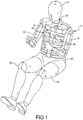
FIG. 1 is a perspective view of one embodiment of a rib cage assembly, according to the present invention, illustrated in operational relationship with a crash test dummy, according to one embodiment of the present invention. -
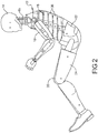
FIG. 2 is a side view of the rib cage assembly illustrated in operational relationship with the crash test dummy ofFIG. 1 . -
FIG. 3 is a top view of one embodiment of a three-dimensional rib, according to the present invention, for the rib cage assembly ofFIGS. 1 and2 . -
FIG. 4 is a side view of the three-dimensional rib ofFIG. 3 . -
FIG. 5 is a sectional view taken along line 5-5 ofFIG. 4 . -
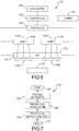
FIG. 6 is a schematic view of one embodiment of a three-dimensional printing system for printing the three-dimensional ribs ofFIGS. 3 through 5 . -
FIG. 7 is a flowchart of a method, according to the present invention, for three-dimensional printing of the three-dimensional ribs ofFIGS. 3 through 5 . - Referring to the drawings and in particular
FIGS. 1 and2 , one embodiment of a crash test dummy, according to one embodiment of the present invention, is generally indicated at 12. Thecrash test dummy 12 is of a fifth percentile (5%) female type and is illustrated in a sitting position. Thiscrash test dummy 12 is used primarily to test the performance of automotive interiors and restraint systems for adult front and rear seat occupants. The size and weight of thecrash test dummy 12 are based on anthropometric studies, which are typically done separately by the following organizations, University of Michigan Transportation Research Institute (UMTRI), U.S. Military Anthropometry Survey (ANSUR), and Civilian American and European Surface Anthropometry Resource (CESAR). It should be appreciated that ranges of motions, centers of gravity, and segment masses simulate those of human subjects defined by the anthropometric data. - As illustrated in
FIGS. 1 and2 , thecrash test dummy 12 includes ahead assembly 14, which includes a one-piece plastic skull, an instrumentation core, and a vinyl skin. The instrumentation core is removable for access to head instrumentation contained inside thehead assembly 14. - The
crash test dummy 12 also includes aspine assembly 15 having an upper end mounted to thehead assembly 14 by a nodding block (not shown) and a nodding joint (not shown). Thespine assembly 15 has a lower end extending into a torso area of thecrash test dummy 12 and is connected to a spine mounting weldment (not shown) by an adapter assembly (not shown). - The
crash test dummy 12 includes a torso orrib cage assembly 16 connected to thespine assembly 15. Thespine assembly 15 also includes a neck connected to thehead assembly 14 and a spine box (not shown) connected to the neck. The neck has a lower end connected to by a suitable attachment such as one or more fasteners (not shown) to the spine box. It should be appreciated that the fasteners threadably engage apertures (not shown) in the spine box to secure the neck to the spine box. Thecrash test dummy 12 also has a pair of arm assemblies including aright arm assembly 18 and aleft arm assembly 20, which are attached to thecrash test dummy 12. Theleft arm assembly 20 includes a clavicle link (not shown), which connects a clavicle (not shown) to the top of thespine assembly 15. It should be appreciated that theright arm assembly 18 is constructed in a similar manner. - As illustrated in the
FIGS. 1 and2 , a lower end of the lumbar spine is connected to a lumbar-thoracic adapter (not shown), which is connected to a lumbar to pelvic adapter (not shown). Thecrash test dummy 12 includes apelvis assembly 22 connected to the adapter. Thecrash test dummy 12 also includes aright leg assembly 24 and aleft leg assembly 26, which are attached to thepelvis assembly 22. It should be appreciated that various components of thecrash test dummy 12 are covered in a urethane, PVC, or Acrylic skin such as a flesh and skin assembly (not shown) for improved coupling with the skeleton of thecrash test dummy 12. It should also be appreciated that a lifting ring (not shown) may be attached to thehead assembly 14 for lifting thecrash test dummy 12 into and out of test fixtures and vehicles. - Referring to
FIGS. 1 and2 , therib cage assembly 16 includes one or more three-dimensional ribs 36, according to one embodiment of the present invention. Theribs 36 extend between the spine box and asternum 34. As illustrated in one embodiment inFIGS. 3-5 for a rib #3, theribs 36 are generally arcuate and rectangular in shape, but may be any suitable shape. Theribs 36 are vertically spaced along the spine box andsternum 34. Theribs 36 are connected to the spine box andsternum 34 by a suitable mechanism such as fasteners (not shown). - Each of the
ribs 36 has a general "C" shape. Eachrib 36 has at least two layers. In one embodiment, eachrib 36 has afront layer 40 and arear layer 42 with an interior 44 spaced therebetween. Thefront layer 40 andrear layer 42 are made of a band material. The band material includes a mixture of Kevlar®, a registered trademark of DuPont, and nylon based materials or carbon fiber and nylon based materials. Kevlar® is a material formed by combining para-phenylenediamine and terephthaloyl chloride. Aromatic polyamide (aramid) threads are the result. These threads are further refined, by dissolving the threads and spinning them into regular fibers. When woven, Kevlar® forms a strong and flexible material. Nylon is a thermoplastic. Nylon is a generic designation for a family of synthetic polymers, more specifically aliphatic or semi-aromatic polyamides, single substance but the name given to a whole family of very similar materials called polyamides. Different kinds of nylon have different properties. Examples of nylon include nylon 6,nylon 6,12, andnylon - Carbon fibers are usually combined with other materials to form a composite. When combined with a plastic resin such as nylon or molded, the carbon fibers forms a carbon-fiber reinforced polymer (often referred to as carbon fiber) which has a very high strength-to-weight ratio, and is extremely rigid although somewhat brittle. The fibers are about 5-10 micrometers in diameter and composed mostly of carbon atoms.
- Referring to
FIG. 5 , eachlayer rib 36 may include a layer of dampingmaterial 46 disposed or sandwiched in between thelayers rib 36 includes at least one, preferably a plurality ofapertures 48 to allow fasteners (not shown) to extend therethrough for connection of therib cage assembly 16 to thecrash test dummy 12. The printable materials for the damping material are commercially available from Stratasys Ltd., 7665 Commerce Way, Eden Prairie, Minnesota, 55344 and the printable materials for the band material are available from Markforged, 14 Remington Street Suite 103, Cambridge Massachusetts 02138. It should be appreciated that the materials are either FDM Thermoplastics or Polyjet Photopolymers of Stratasys Ltd. It should also be appreciated that the dimensions and thicknesses of theribs 36 will vary depending on the crash test dummy. It should also be appreciated that this process could be applied to other rib designs as well, for example, bigger, smaller, and different shapes. - Referring to
FIG. 6 , a three-dimensional printer or printing system, generally designated 100, includes one or more printing heads 112, and at least two dispensers 114 and individually referenced 114a and 114b, containing printable materials, generally referenced 116 and individually referenced 116a and 116b, respectively. It should be appreciated that other components, and other sets of components, may be used. - The
printing head 112 has a plurality of ink-jet type nozzles 118, through which printable materials 116a and 116b are jetted. In one embodiment, the first dispenser 114a is connected to a first set of nozzles 118a, and second dispenser 114b is connected to a second set of nozzles 118b. Thus first printable material 116a is jetted through the nozzles 118a, and the second printable material 116b is jetted through nozzles 118b. In another embodiment (not shown), the three-dimensional printing system 110 may include at least two printing heads 112. Thefirst printing head 112 is connected to first dispenser 114a and is used to jet first printable material 116a; and thesecond printing head 112 is connected to second dispenser 114b is used to jet second printable material 116b. - The three-
dimensional printing system 110 further includes acontroller 120, a Computer Aided Design (CAD)system 122, acuring unit 124, and optionally apositioning apparatus 126. Thecontroller 120 is coupled to theCAD system 122, curingunit 124,positioning apparatus 126,printing head 112 and each of the dispensers 114. It should be appreciated that control may be effected by other units than shown, such as one or more separate units. - The three-
dimensional rib 36 is built in layers, the depth of each layer typically being controllable by selectively adjusting the output from each of the ink-jet nozzles 118. - By combining or mixing materials from each of the dispensers 114, wherein each dispenser 114 contains printable material having a different properties such as hardness, it is possible to adjust and control the hardness of the material forming the three-
dimensional rib 36 being produced. Thus, by combining the first and second interface materials being output from each of the dispensers 114, respectively, different parts of the three-dimensional rib 36 having a different modulus of elasticity and a different strength may be produced. It should be appreciated that such a three-dimensional printing system is disclosed inU.S. Patent No. 8,481,241 to Napadensky et al. . - Referring to
FIG. 7 , the present invention provides amethod 200, according to one embodiment of the present invention, of making the three-dimensional rib 36 for thecrash test dummy 12. Themethod 200 starts inbubble 202 and advances to block 204. Inblock 204, themethod 200 includes the step of providing a three-dimensional printer orprinting system 110. Themethod 200 advances to block 206 and includes the step of making a CAD model of therib 36. In one embodiment, a CAD model of therib 36 was made to allow the 3D printer to print in one model. Themethod 200 advances to block 208 and includes the step of printing, by the three-dimensional printer orprinting system 110, therib 36 with at least twolayers layer 46 of damping material sandwiched in between thelayers - Accordingly,
rib 36 and therib cage assembly 16 of the present invention hasribs 36 that are even more humanlike than in the past with improved biofidelity. Due to the advantage of the three-dimensional printing of two different materials in one printing, theribs 36 can include hysteresis or damping that can be increased to make theribs 36 more humanlike than ever before. - The present invention has been described in an illustrative manner. It is to be understood that the terminology, which has been used, is intended to be in the nature of words of description rather than of limitation.
- Many modifications and variations of the present invention are possible in light of the above teachings. Therefore, the present invention may be practiced other than as specifically described.
Claims (14)
- A three-dimensional rib (36) for a crash test dummy (12) characterized in that the rib comprises:at least two layers of a band material including a front layer (40) and a rear layer (42) each made of a mixture of a fibrous based material and a polymer based material with an interior (44) spaced therebetween; anda layer of damping material (46) sandwiched in the interior (44) between said at least two layers of said band material.
- A three-dimensional rib (36) as set forth in claim 1 wherein said fibrous based material is one of Kevlar and carbon fiber.
- A three-dimensional rib (36) as set forth in any one of claims 1 or 2 wherein said polymer based material is nylon.
- A three-dimensional rib (36) as set forth in any one of claims 1-3 wherein each of said at least two layers of said band material has a thickness from approximately 2.0 millimeters to approximately 6.0 millimeters.
- A three-dimensional rib (36) as set forth in any one of claims 1-4 wherein said layer of said damping material (46) has a thickness from approximately 8.0 millimeters to approximately 10.0 millimeters.
- A three-dimensional rib (36) as set forth in any one of claims 1-5 wherein said layer of damping material (46) has a thickness greater than a thickness of each of said at least two layers of said band material.
- A method of making three-dimensional rib (36) for a crash test dummy (12), said method comprising the steps of:providing a three-dimensional printer;making a CAD model of a three-dimensional rib (36) for the crash test dummy (12);printing, by the three-dimensional printer, the three-dimensional rib (36) with at least two layers of a band material including a front layer (40) and a rear layer (42) each made of a mixture of a fibrous based material and a polymer based material with an interior (44) spaced therebetween and a layer of damping material (46) sandwiched in the interior (44) between the layers of the band material.
- A method as set forth in claim 7 wherein the fibrous based material is one of Kevlar or carbon fiber.
- A method as set forth in any one of claims 7 or 8 wherein the polymer based material is nylon.
- A method as set forth in any one of claims 7-9 wherein said step of printing comprises printing the at least two layers of the band material in one printing and printing the layer of damping material (46) in another printing.
- A method as set forth in any one of claims 7-10 wherein the layer of the damping material (46) has a thickness from approximately 8.0 millimeters to approximately 10.0 millimeters.
- A method as set forth in any one of claims 7-11 wherein each of the at least two layers of the band material has a thickness from approximately 2.0 millimeters to approximately 6.0 millimeters.
- A rib cage assembly including a plurality of three-dimensional ribs (36) as set forth in any one of claims 1-6.
- A crash test dummy comprising:a body; anda rib cage assembly as set forth in claim 13 operatively attached to said body.
Applications Claiming Priority (2)
| Application Number | Priority Date | Filing Date | Title |
|---|---|---|---|
| US201762449525P | 2017-01-23 | 2017-01-23 | |
| US15/847,498 US20180211564A1 (en) | 2017-01-23 | 2017-12-19 | Three-dimensional ribs for crash test dummy |
Publications (2)
| Publication Number | Publication Date |
|---|---|
| EP3352156A1 EP3352156A1 (en) | 2018-07-25 |
| EP3352156B1 true EP3352156B1 (en) | 2019-11-27 |
Family
ID=61005748
Family Applications (1)
| Application Number | Title | Priority Date | Filing Date |
|---|---|---|---|
| EP18152182.4A Active EP3352156B1 (en) | 2017-01-23 | 2018-01-17 | Three-dimensional ribs for crash test dummy |
Country Status (3)
| Country | Link |
|---|---|
| US (1) | US20180211564A1 (en) |
| EP (1) | EP3352156B1 (en) |
| ES (1) | ES2769525T3 (en) |
Families Citing this family (2)
| Publication number | Priority date | Publication date | Assignee | Title |
|---|---|---|---|---|
| CN112435559B (en) * | 2020-11-15 | 2022-07-15 | 北京航空航天大学 | A method for making a body-warming dummy with a built-in stretchable circuit and a body-warming dummy |
| CN119935571B (en) * | 2025-01-03 | 2025-12-05 | 南京理工大学 | A collision dummy thoracic structure that reflects the movement characteristics of the human thoracic ribcage |
Family Cites Families (4)
| Publication number | Priority date | Publication date | Assignee | Title |
|---|---|---|---|---|
| US8481241B2 (en) * | 2000-03-13 | 2013-07-09 | Stratasys Ltd. | Compositions and methods for use in three dimensional model printing |
| US7857626B2 (en) * | 2000-10-23 | 2010-12-28 | Toly Christopher C | Medical physiological simulator including a conductive elastomer layer |
| US6780016B1 (en) * | 2000-10-23 | 2004-08-24 | Christopher C. Toly | Human surgical trainer and methods for training |
| US9142146B2 (en) * | 2012-06-04 | 2015-09-22 | The Johns Hopkins University | Cranial bone surrogate and methods of manufacture thereof |
-
2017
- 2017-12-19 US US15/847,498 patent/US20180211564A1/en not_active Abandoned
-
2018
- 2018-01-17 EP EP18152182.4A patent/EP3352156B1/en active Active
- 2018-01-17 ES ES18152182T patent/ES2769525T3/en active Active
Non-Patent Citations (1)
| Title |
|---|
| None * |
Also Published As
| Publication number | Publication date |
|---|---|
| ES2769525T3 (en) | 2020-06-26 |
| EP3352156A1 (en) | 2018-07-25 |
| US20180211564A1 (en) | 2018-07-26 |
Similar Documents
| Publication | Publication Date | Title |
|---|---|---|
| EP3179465B1 (en) | Three-dimensionally printed internal organs for crash test dummy | |
| US20170301262A1 (en) | Three-dimensional components and method of three-dimensional printing of components for crash test dummy | |
| US20170301264A1 (en) | Three-dimensionally printed internal flesh and organs for crash test dummy | |
| Iwamoto et al. | Development of advanced human models in THUMS | |
| US20190371207A1 (en) | Internal organ assembly for crash test dummy | |
| US9972220B2 (en) | Omnidirectional neck assembly for crash test dummy | |
| US10262557B2 (en) | Omni-directional shoulder assembly for crash test dummy | |
| US10733911B2 (en) | Three-dimensional ribs and method of three-dimensional printing of ribs for crash test dummy | |
| EP3352156A1 (en) | Three-dimensional ribs for crash test dummy | |
| EP3273430A1 (en) | Three-dimensional components and method of three-dimensional printing of components for crash test dummy | |
| US20180247567A1 (en) | Head assembly with facial insert for crash test dummy | |
| de Jager et al. | Assessing new child dummies and criteria for child occupant protection in frontal impact | |
| EP3273431B1 (en) | Three-dimensionally printed internal flesh and organs for crash test dummy | |
| Shams et al. | Development of THOR NT: Enhancement of THOR Alpha–The NHTSA advanced frontal dummy | |
| EP3223264A1 (en) | Ribs for crash test dummy | |
| Mueller et al. | Letter from the Special Issue Editors: Student Special Issue: Collection of papers presented at the 18th Annual Injury Biomechanics Symposium at The Ohio State University | |
| Alderson | The development of anthropomorphic test dummies to match specific human responses to accelerations and impacts | |
| Du et al. | Restraint harness performance during flight maneuvers: A parametric study | |
| Guizzo | Anatomy of a crash-test dummy | |
| Bońkowski | Použití modelů lidského těla v pasivní bezpečnosti motocyklů | |
| Khaksar | Numerical modelling of the effects of vibration in helicopters for prediction and analysis of human comfort assessment | |
| Faria-Pereira Pérez de Rada | Validation of the Female 50th Percentile Active Human Model | |
| Patil | Modeling and evaluation of child safety seat and restraint system for aerospace application | |
| Assandri | Human Body Model and Passive Safety in Autonomous vehicles: Far Side Impact | |
| Rodríguez | FIREWALL AND DRIVER’S SEAT FOR FORMULA STUDENT RACE CAR FEST11 |
Legal Events
| Date | Code | Title | Description |
|---|---|---|---|
| PUAI | Public reference made under article 153(3) epc to a published international application that has entered the european phase |
Free format text: ORIGINAL CODE: 0009012 |
|
| STAA | Information on the status of an ep patent application or granted ep patent |
Free format text: STATUS: REQUEST FOR EXAMINATION WAS MADE |
|
| 17P | Request for examination filed |
Effective date: 20180117 |
|
| AK | Designated contracting states |
Kind code of ref document: A1 Designated state(s): AL AT BE BG CH CY CZ DE DK EE ES FI FR GB GR HR HU IE IS IT LI LT LU LV MC MK MT NL NO PL PT RO RS SE SI SK SM TR |
|
| AX | Request for extension of the european patent |
Extension state: BA ME |
|
| REG | Reference to a national code |
Ref country code: DE Ref legal event code: R079 Ref document number: 602018001308 Country of ref document: DE Free format text: PREVIOUS MAIN CLASS: G09B0023280000 Ipc: B29K0077000000 |
|
| RIC1 | Information provided on ipc code assigned before grant |
Ipc: B29K 77/00 20060101AFI20190612BHEP Ipc: B33Y 80/00 20150101ALI20190612BHEP Ipc: G09B 23/30 20060101ALI20190612BHEP Ipc: B29K 307/04 20060101ALI20190612BHEP Ipc: B33Y 50/00 20150101ALI20190612BHEP Ipc: G09B 23/28 20060101ALI20190612BHEP Ipc: B29C 64/386 20170101ALI20190612BHEP |
|
| GRAP | Despatch of communication of intention to grant a patent |
Free format text: ORIGINAL CODE: EPIDOSNIGR1 |
|
| STAA | Information on the status of an ep patent application or granted ep patent |
Free format text: STATUS: GRANT OF PATENT IS INTENDED |
|
| INTG | Intention to grant announced |
Effective date: 20190726 |
|
| RIN1 | Information on inventor provided before grant (corrected) |
Inventor name: BEEBE, MICHAEL SCOTT Inventor name: KRIS, SULLENBERGER Inventor name: UBOM, IME VICTOR Inventor name: BURLEIGH, MARK JOHN Inventor name: VARA, THOMAS M. |
|
| GRAS | Grant fee paid |
Free format text: ORIGINAL CODE: EPIDOSNIGR3 |
|
| GRAA | (expected) grant |
Free format text: ORIGINAL CODE: 0009210 |
|
| STAA | Information on the status of an ep patent application or granted ep patent |
Free format text: STATUS: THE PATENT HAS BEEN GRANTED |
|
| AK | Designated contracting states |
Kind code of ref document: B1 Designated state(s): AL AT BE BG CH CY CZ DE DK EE ES FI FR GB GR HR HU IE IS IT LI LT LU LV MC MK MT NL NO PL PT RO RS SE SI SK SM TR |
|
| REG | Reference to a national code |
Ref country code: GB Ref legal event code: FG4D |
|
| REG | Reference to a national code |
Ref country code: CH Ref legal event code: EP |
|
| REG | Reference to a national code |
Ref country code: AT Ref legal event code: REF Ref document number: 1206199 Country of ref document: AT Kind code of ref document: T Effective date: 20191215 |
|
| REG | Reference to a national code |
Ref country code: DE Ref legal event code: R096 Ref document number: 602018001308 Country of ref document: DE |
|
| REG | Reference to a national code |
Ref country code: IE Ref legal event code: FG4D |
|
| REG | Reference to a national code |
Ref country code: NL Ref legal event code: MP Effective date: 20191127 |
|
| REG | Reference to a national code |
Ref country code: LT Ref legal event code: MG4D |
|
| PG25 | Lapsed in a contracting state [announced via postgrant information from national office to epo] |
Ref country code: FI Free format text: LAPSE BECAUSE OF FAILURE TO SUBMIT A TRANSLATION OF THE DESCRIPTION OR TO PAY THE FEE WITHIN THE PRESCRIBED TIME-LIMIT Effective date: 20191127 Ref country code: BG Free format text: LAPSE BECAUSE OF FAILURE TO SUBMIT A TRANSLATION OF THE DESCRIPTION OR TO PAY THE FEE WITHIN THE PRESCRIBED TIME-LIMIT Effective date: 20200227 Ref country code: LT Free format text: LAPSE BECAUSE OF FAILURE TO SUBMIT A TRANSLATION OF THE DESCRIPTION OR TO PAY THE FEE WITHIN THE PRESCRIBED TIME-LIMIT Effective date: 20191127 Ref country code: NO Free format text: LAPSE BECAUSE OF FAILURE TO SUBMIT A TRANSLATION OF THE DESCRIPTION OR TO PAY THE FEE WITHIN THE PRESCRIBED TIME-LIMIT Effective date: 20200227 Ref country code: GR Free format text: LAPSE BECAUSE OF FAILURE TO SUBMIT A TRANSLATION OF THE DESCRIPTION OR TO PAY THE FEE WITHIN THE PRESCRIBED TIME-LIMIT Effective date: 20200228 Ref country code: LV Free format text: LAPSE BECAUSE OF FAILURE TO SUBMIT A TRANSLATION OF THE DESCRIPTION OR TO PAY THE FEE WITHIN THE PRESCRIBED TIME-LIMIT Effective date: 20191127 Ref country code: SE Free format text: LAPSE BECAUSE OF FAILURE TO SUBMIT A TRANSLATION OF THE DESCRIPTION OR TO PAY THE FEE WITHIN THE PRESCRIBED TIME-LIMIT Effective date: 20191127 Ref country code: NL Free format text: LAPSE BECAUSE OF FAILURE TO SUBMIT A TRANSLATION OF THE DESCRIPTION OR TO PAY THE FEE WITHIN THE PRESCRIBED TIME-LIMIT Effective date: 20191127 |
|
| PG25 | Lapsed in a contracting state [announced via postgrant information from national office to epo] |
Ref country code: HR Free format text: LAPSE BECAUSE OF FAILURE TO SUBMIT A TRANSLATION OF THE DESCRIPTION OR TO PAY THE FEE WITHIN THE PRESCRIBED TIME-LIMIT Effective date: 20191127 Ref country code: RS Free format text: LAPSE BECAUSE OF FAILURE TO SUBMIT A TRANSLATION OF THE DESCRIPTION OR TO PAY THE FEE WITHIN THE PRESCRIBED TIME-LIMIT Effective date: 20191127 Ref country code: IS Free format text: LAPSE BECAUSE OF FAILURE TO SUBMIT A TRANSLATION OF THE DESCRIPTION OR TO PAY THE FEE WITHIN THE PRESCRIBED TIME-LIMIT Effective date: 20200327 |
|
| REG | Reference to a national code |
Ref country code: ES Ref legal event code: FG2A Ref document number: 2769525 Country of ref document: ES Kind code of ref document: T3 Effective date: 20200626 |
|
| PG25 | Lapsed in a contracting state [announced via postgrant information from national office to epo] |
Ref country code: AL Free format text: LAPSE BECAUSE OF FAILURE TO SUBMIT A TRANSLATION OF THE DESCRIPTION OR TO PAY THE FEE WITHIN THE PRESCRIBED TIME-LIMIT Effective date: 20191127 |
|
| PG25 | Lapsed in a contracting state [announced via postgrant information from national office to epo] |
Ref country code: PT Free format text: LAPSE BECAUSE OF FAILURE TO SUBMIT A TRANSLATION OF THE DESCRIPTION OR TO PAY THE FEE WITHIN THE PRESCRIBED TIME-LIMIT Effective date: 20200419 Ref country code: EE Free format text: LAPSE BECAUSE OF FAILURE TO SUBMIT A TRANSLATION OF THE DESCRIPTION OR TO PAY THE FEE WITHIN THE PRESCRIBED TIME-LIMIT Effective date: 20191127 Ref country code: DK Free format text: LAPSE BECAUSE OF FAILURE TO SUBMIT A TRANSLATION OF THE DESCRIPTION OR TO PAY THE FEE WITHIN THE PRESCRIBED TIME-LIMIT Effective date: 20191127 Ref country code: RO Free format text: LAPSE BECAUSE OF FAILURE TO SUBMIT A TRANSLATION OF THE DESCRIPTION OR TO PAY THE FEE WITHIN THE PRESCRIBED TIME-LIMIT Effective date: 20191127 Ref country code: CZ Free format text: LAPSE BECAUSE OF FAILURE TO SUBMIT A TRANSLATION OF THE DESCRIPTION OR TO PAY THE FEE WITHIN THE PRESCRIBED TIME-LIMIT Effective date: 20191127 |
|
| REG | Reference to a national code |
Ref country code: DE Ref legal event code: R097 Ref document number: 602018001308 Country of ref document: DE |
|
| PG25 | Lapsed in a contracting state [announced via postgrant information from national office to epo] |
Ref country code: MC Free format text: LAPSE BECAUSE OF FAILURE TO SUBMIT A TRANSLATION OF THE DESCRIPTION OR TO PAY THE FEE WITHIN THE PRESCRIBED TIME-LIMIT Effective date: 20191127 Ref country code: SM Free format text: LAPSE BECAUSE OF FAILURE TO SUBMIT A TRANSLATION OF THE DESCRIPTION OR TO PAY THE FEE WITHIN THE PRESCRIBED TIME-LIMIT Effective date: 20191127 Ref country code: SK Free format text: LAPSE BECAUSE OF FAILURE TO SUBMIT A TRANSLATION OF THE DESCRIPTION OR TO PAY THE FEE WITHIN THE PRESCRIBED TIME-LIMIT Effective date: 20191127 |
|
| REG | Reference to a national code |
Ref country code: AT Ref legal event code: MK05 Ref document number: 1206199 Country of ref document: AT Kind code of ref document: T Effective date: 20191127 |
|
| PLBE | No opposition filed within time limit |
Free format text: ORIGINAL CODE: 0009261 |
|
| STAA | Information on the status of an ep patent application or granted ep patent |
Free format text: STATUS: NO OPPOSITION FILED WITHIN TIME LIMIT |
|
| REG | Reference to a national code |
Ref country code: BE Ref legal event code: MM Effective date: 20200131 |
|
| PG25 | Lapsed in a contracting state [announced via postgrant information from national office to epo] |
Ref country code: LU Free format text: LAPSE BECAUSE OF NON-PAYMENT OF DUE FEES Effective date: 20200117 |
|
| 26N | No opposition filed |
Effective date: 20200828 |
|
| PG25 | Lapsed in a contracting state [announced via postgrant information from national office to epo] |
Ref country code: PL Free format text: LAPSE BECAUSE OF FAILURE TO SUBMIT A TRANSLATION OF THE DESCRIPTION OR TO PAY THE FEE WITHIN THE PRESCRIBED TIME-LIMIT Effective date: 20191127 Ref country code: SI Free format text: LAPSE BECAUSE OF FAILURE TO SUBMIT A TRANSLATION OF THE DESCRIPTION OR TO PAY THE FEE WITHIN THE PRESCRIBED TIME-LIMIT Effective date: 20191127 Ref country code: BE Free format text: LAPSE BECAUSE OF NON-PAYMENT OF DUE FEES Effective date: 20200131 Ref country code: AT Free format text: LAPSE BECAUSE OF FAILURE TO SUBMIT A TRANSLATION OF THE DESCRIPTION OR TO PAY THE FEE WITHIN THE PRESCRIBED TIME-LIMIT Effective date: 20191127 |
|
| PG25 | Lapsed in a contracting state [announced via postgrant information from national office to epo] |
Ref country code: IT Free format text: LAPSE BECAUSE OF FAILURE TO SUBMIT A TRANSLATION OF THE DESCRIPTION OR TO PAY THE FEE WITHIN THE PRESCRIBED TIME-LIMIT Effective date: 20191127 Ref country code: IE Free format text: LAPSE BECAUSE OF NON-PAYMENT OF DUE FEES Effective date: 20200117 |
|
| REG | Reference to a national code |
Ref country code: CH Ref legal event code: PL |
|
| PG25 | Lapsed in a contracting state [announced via postgrant information from national office to epo] |
Ref country code: LI Free format text: LAPSE BECAUSE OF NON-PAYMENT OF DUE FEES Effective date: 20210131 Ref country code: CH Free format text: LAPSE BECAUSE OF NON-PAYMENT OF DUE FEES Effective date: 20210131 |
|
| PG25 | Lapsed in a contracting state [announced via postgrant information from national office to epo] |
Ref country code: TR Free format text: LAPSE BECAUSE OF FAILURE TO SUBMIT A TRANSLATION OF THE DESCRIPTION OR TO PAY THE FEE WITHIN THE PRESCRIBED TIME-LIMIT Effective date: 20191127 Ref country code: MT Free format text: LAPSE BECAUSE OF FAILURE TO SUBMIT A TRANSLATION OF THE DESCRIPTION OR TO PAY THE FEE WITHIN THE PRESCRIBED TIME-LIMIT Effective date: 20191127 Ref country code: CY Free format text: LAPSE BECAUSE OF FAILURE TO SUBMIT A TRANSLATION OF THE DESCRIPTION OR TO PAY THE FEE WITHIN THE PRESCRIBED TIME-LIMIT Effective date: 20191127 |
|
| PGFP | Annual fee paid to national office [announced via postgrant information from national office to epo] |
Ref country code: ES Payment date: 20220201 Year of fee payment: 5 |
|
| PG25 | Lapsed in a contracting state [announced via postgrant information from national office to epo] |
Ref country code: MK Free format text: LAPSE BECAUSE OF FAILURE TO SUBMIT A TRANSLATION OF THE DESCRIPTION OR TO PAY THE FEE WITHIN THE PRESCRIBED TIME-LIMIT Effective date: 20191127 |
|
| P01 | Opt-out of the competence of the unified patent court (upc) registered |
Effective date: 20230524 |
|
| REG | Reference to a national code |
Ref country code: ES Ref legal event code: FD2A Effective date: 20240326 |
|
| PG25 | Lapsed in a contracting state [announced via postgrant information from national office to epo] |
Ref country code: ES Free format text: LAPSE BECAUSE OF NON-PAYMENT OF DUE FEES Effective date: 20230118 |
|
| PG25 | Lapsed in a contracting state [announced via postgrant information from national office to epo] |
Ref country code: ES Free format text: LAPSE BECAUSE OF NON-PAYMENT OF DUE FEES Effective date: 20230118 |
|
| PGFP | Annual fee paid to national office [announced via postgrant information from national office to epo] |
Ref country code: GB Payment date: 20240129 Year of fee payment: 7 |
|
| PGFP | Annual fee paid to national office [announced via postgrant information from national office to epo] |
Ref country code: FR Payment date: 20240125 Year of fee payment: 7 |
|
| PGFP | Annual fee paid to national office [announced via postgrant information from national office to epo] |
Ref country code: DE Payment date: 20250129 Year of fee payment: 8 |
|
| GBPC | Gb: european patent ceased through non-payment of renewal fee |
Effective date: 20250117 |
|
| PG25 | Lapsed in a contracting state [announced via postgrant information from national office to epo] |
Ref country code: GB Free format text: LAPSE BECAUSE OF NON-PAYMENT OF DUE FEES Effective date: 20250117 |
|
| PG25 | Lapsed in a contracting state [announced via postgrant information from national office to epo] |
Ref country code: FR Free format text: LAPSE BECAUSE OF NON-PAYMENT OF DUE FEES Effective date: 20250131 |