EP3351927A1 - Inspection system, controller, inspection method, and inspection program - Google Patents
Inspection system, controller, inspection method, and inspection program Download PDFInfo
- Publication number
- EP3351927A1 EP3351927A1 EP17197451.2A EP17197451A EP3351927A1 EP 3351927 A1 EP3351927 A1 EP 3351927A1 EP 17197451 A EP17197451 A EP 17197451A EP 3351927 A1 EP3351927 A1 EP 3351927A1
- Authority
- EP
- European Patent Office
- Prior art keywords
- inspected
- workpiece
- omnidirectional camera
- input image
- capturing
- Prior art date
- Legal status (The legal status is an assumption and is not a legal conclusion. Google has not performed a legal analysis and makes no representation as to the accuracy of the status listed.)
- Granted
Links
Images





Classifications
-
- G—PHYSICS
- G06—COMPUTING OR CALCULATING; COUNTING
- G06T—IMAGE DATA PROCESSING OR GENERATION, IN GENERAL
- G06T7/00—Image analysis
- G06T7/0002—Inspection of images, e.g. flaw detection
- G06T7/0004—Industrial image inspection
- G06T7/001—Industrial image inspection using an image reference approach
-
- B—PERFORMING OPERATIONS; TRANSPORTING
- B25—HAND TOOLS; PORTABLE POWER-DRIVEN TOOLS; MANIPULATORS
- B25J—MANIPULATORS; CHAMBERS PROVIDED WITH MANIPULATION DEVICES
- B25J9/00—Program-controlled manipulators
- B25J9/003—Program-controlled manipulators having parallel kinematics
-
- B—PERFORMING OPERATIONS; TRANSPORTING
- B25—HAND TOOLS; PORTABLE POWER-DRIVEN TOOLS; MANIPULATORS
- B25J—MANIPULATORS; CHAMBERS PROVIDED WITH MANIPULATION DEVICES
- B25J19/00—Accessories fitted to manipulators, e.g. for monitoring, for viewing; Safety devices combined with or specially adapted for use in connection with manipulators
- B25J19/02—Sensing devices
- B25J19/04—Viewing devices
-
- G—PHYSICS
- G01—MEASURING; TESTING
- G01N—INVESTIGATING OR ANALYSING MATERIALS BY DETERMINING THEIR CHEMICAL OR PHYSICAL PROPERTIES
- G01N21/00—Investigating or analysing materials by the use of optical means, i.e. using sub-millimetre waves, infrared, visible or ultraviolet light
- G01N21/84—Systems specially adapted for particular applications
- G01N21/88—Investigating the presence of flaws or contamination
- G01N21/8806—Specially adapted optical and illumination features
-
- G—PHYSICS
- G06—COMPUTING OR CALCULATING; COUNTING
- G06T—IMAGE DATA PROCESSING OR GENERATION, IN GENERAL
- G06T7/00—Image analysis
- G06T7/0002—Inspection of images, e.g. flaw detection
- G06T7/0004—Industrial image inspection
-
- G—PHYSICS
- G06—COMPUTING OR CALCULATING; COUNTING
- G06T—IMAGE DATA PROCESSING OR GENERATION, IN GENERAL
- G06T7/00—Image analysis
- G06T7/70—Determining position or orientation of objects or cameras
-
- G—PHYSICS
- G06—COMPUTING OR CALCULATING; COUNTING
- G06T—IMAGE DATA PROCESSING OR GENERATION, IN GENERAL
- G06T7/00—Image analysis
- G06T7/70—Determining position or orientation of objects or cameras
- G06T7/73—Determining position or orientation of objects or cameras using feature-based methods
- G06T7/74—Determining position or orientation of objects or cameras using feature-based methods involving reference images or patches
-
- H—ELECTRICITY
- H04—ELECTRIC COMMUNICATION TECHNIQUE
- H04N—PICTORIAL COMMUNICATION, e.g. TELEVISION
- H04N23/00—Cameras or camera modules comprising electronic image sensors; Control thereof
- H04N23/58—Means for changing the camera field of view without moving the camera body, e.g. nutating or panning of optics or image sensors
-
- H—ELECTRICITY
- H04—ELECTRIC COMMUNICATION TECHNIQUE
- H04N—PICTORIAL COMMUNICATION, e.g. TELEVISION
- H04N23/00—Cameras or camera modules comprising electronic image sensors; Control thereof
- H04N23/60—Control of cameras or camera modules
- H04N23/698—Control of cameras or camera modules for achieving an enlarged field of view, e.g. panoramic image capture
-
- G—PHYSICS
- G06—COMPUTING OR CALCULATING; COUNTING
- G06T—IMAGE DATA PROCESSING OR GENERATION, IN GENERAL
- G06T2207/00—Indexing scheme for image analysis or image enhancement
- G06T2207/10—Image acquisition modality
- G06T2207/10004—Still image; Photographic image
-
- G—PHYSICS
- G06—COMPUTING OR CALCULATING; COUNTING
- G06T—IMAGE DATA PROCESSING OR GENERATION, IN GENERAL
- G06T2207/00—Indexing scheme for image analysis or image enhancement
- G06T2207/30—Subject of image; Context of image processing
- G06T2207/30108—Industrial image inspection
- G06T2207/30164—Workpiece; Machine component
-
- G—PHYSICS
- G06—COMPUTING OR CALCULATING; COUNTING
- G06T—IMAGE DATA PROCESSING OR GENERATION, IN GENERAL
- G06T2207/00—Indexing scheme for image analysis or image enhancement
- G06T2207/30—Subject of image; Context of image processing
- G06T2207/30204—Marker
Definitions
- the present disclosure relates to a technology for inspecting an object to be inspected by using an omnidirectional camera.
- Patent Document 1 JP 2000-180382 A discloses a visual inspection device that can inspect, at a high speed, a surface of an object to be inspected randomly placed on a conveyor. More specifically, the visual inspection device captures an object to be inspected conveyed on a conveyor from different directions with a plurality of cameras. The visual inspection device then inspects the object to be inspected by using input images obtained by capturing the object to be inspected from different directions.
- Patent Document 1 JP 2000-180382 A
- the visual inspection device disclosed in Patent Document 1 needs to include a plurality of cameras in order to capture an object to be inspected from various directions. This leads to high costs of the visual inspection device and a complicated configuration of the visual inspection device. Therefore, a technology for inspecting an external appearance of an object to be inspected from various directions with one camera is desired.
- an inspection system for inspecting an object to be inspected includes: an omnidirectional camera; a movement device configured to cause the object to be inspected to circle around the omnidirectional camera in a state where a posture of the object to be inspected is maintained; an acquisition unit configured to output a capturing instruction to the omnidirectional camera at a plurality of timings while the movement device causes the object to be inspected to circle around the omnidirectional camera, the acquisition unit being configured to acquire, from the omnidirectional camera, a plurality of input images indicating the object to be inspected from different directions; and an inspector configured to inspect the object to be inspected by using the plurality of input images.
- the movement device causes the object to be inspected to circle around the omnidirectional camera in a state where a constant distance is maintained from the omnidirectional camera to the object to be inspected.
- the movement device does not stop the object to be inspected while the object to be inspected is circling around the omnidirectional camera.
- the inspection system further includes: a storage configured to associate and store a reference image obtained by capturing in advance an object of a type identical to the object to be inspected from a different direction with a direction of the object shown in the reference image; and an identification unit configured to identify a first direction of the object to be inspected shown in a first input image of the plurality of input images and a second direction of the object to be inspected shown in a second input image of the plurality of input images.
- the inspector compares the reference image associated with the first direction with the first input image, compares the reference image associated with the second direction with the second input image, and inspects the object to be inspected based on a result of the comparison.
- the identification unit identifies the first direction based on a position of the object to be inspected at a capturing timing of the first input image, and a position of the omnidirectional camera, and identifies the second direction based on a position of the object to be inspected at a capturing timing of the second input image, and the position of the omnidirectional camera.
- different marks are put at different positions on a surface of the movement device.
- the plurality of marks are associated in advance with directions of the object to be inspected.
- the identification unit identifies each of the directions associated with each of the marks shown in the first input image as the first direction, and identifies each of the directions associated with each of the marks shown in the second input image as the second direction.
- the inspector identifies the position of the object to be inspected shown in the first input image based on a positional relationship between the position of the object to be inspected at the capturing timing of the first input image and the omnidirectional camera, the inspector comparing the object to be inspected shown at the position with the reference image associated with the first direction; identifies the position of the object to be inspected shown in the second input image based on a positional relationship between the position of the object to be inspected at the capturing timing of the second input image and the omnidirectional camera, the inspector comparing the object to be inspected shown at the position with the reference image associated with the second direction; and inspects the object to be inspected based on a result of the comparison.
- a controller for controlling a movement device for moving an object to be inspected and an omnidirectional camera for capturing the object to be inspected includes: an acquisition unit configured to output, to the movement device, an instruction for causing the object to be inspected to circle around the omnidirectional camera in a state where a posture of the object to be inspected is maintained, to output a capturing instruction to the omnidirectional camera at a plurality of timings while the movement device causes the object to be inspected to circle around the omnidirectional camera, and to acquire, from the omnidirectional camera, a plurality of input images indicating the object to be inspected from different directions; and an inspector configured to inspect the object to be inspected by using the plurality of input images.
- an inspection method for inspecting an object to be inspected includes: causing the object to be inspected to circle around an omnidirectional camera in a state where a posture of the object to be inspected is maintained; outputting a capturing instruction to the omnidirectional camera at a plurality of timings while the object to be inspected is circling around the omnidirectional camera, and acquiring, from the omnidirectional camera, a plurality of input images indicating the object to be inspected from different directions; and inspecting the object to be inspected by using the plurality of input images.
- a non-transitory computer-readable storage medium storing an inspection program for inspecting an object to be inspected, the inspection program causing a computer to execute: causing the object to be inspected to circle around an omnidirectional camera in a state where a posture of the object to be inspected is maintained; outputting a capturing instruction to the omnidirectional camera at a plurality of timings while the object to be inspected is circling around the omnidirectional camera, and acquiring, from the omnidirectional camera, a plurality of input images indicating the object to be inspected from different directions; and inspecting the object to be inspected by using the plurality of input images.
- an external appearance of an object to be inspected can be inspected from various directions with one camera.
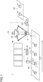
- FIG. 1 is a schematic view illustrating a basic configuration of an inspection system 1 according to the embodiment.
- the inspection system 1 includes, for example, a controller 100, a robot 200 that serves as a movement device, and an omnidirectional camera 300.
- the controller 100 is, for example, a programmable logic controller (PLC), and controls the entire inspection system 1.
- PLC programmable logic controller
- the controller 100 controls devices such as an image sensor 51, the robot 200, and the omnidirectional camera 300.
- the controller 100 is connected, for example, to a field network 54 in a daisy chain with the image sensor 51 and a counter 52.
- a field network 54 for example, EtherCAT (registered trademark) is employed.
- the controller 100 has a communication linkage with the robot 200 via a field network 56.
- EtherNET registered trademark
- the inspection system 1 performs predetermined work on a workpiece W (object to be inspected) conveyed on a conveyor 20A.
- the workpiece W is a product or semi-finished product, and for example, may be an electronic component or a food.
- the image sensor 51 regularly captures the conveyor 20A and detects the workpiece W from an obtained input image.
- the image sensor 51 detects the workpiece W by image processing such as template matching.
- a coordinate value of the workpiece W in the input image is output to the controller 100.
- the counter 52 measures a movement amount of the conveyor 20A based on a pulse wave generated from an encoder 53. More specifically, the encoder 53 generates a pulse signal according to the movement amount of the conveyor 20A. The counter 52 receives the pulse signal from the encoder 53 and counts the number of pulses included in the pulse signal to measure the movement amount of the conveyor 20A. The counter 52 then transmits a counted value of the pulse wave to the controller 100 at constant communication intervals.
- the controller 100 substitutes the coordinate value (camera coordinate system) of the workpiece W in the input image received from the image sensor 51 into a coordinate transformation equation determined in advance.
- the controller 100 then transforms the coordinate value of the workpiece W of the camera coordinate system into a coordinate value of a world coordinate system.
- the world coordinate system is a coordinate system for controlling the robot 200. Every time the controller 100 receives the counted value from the counter 52, the controller 100 calculates the movement amount from last time on the conveyor 20A.
- the controller 100 adds the movement amount to the coordinate value of the workpiece W indicated in the world coordinate system.
- the movement amount of the conveyor 20A corresponding to one count is set in advance.
- the controller 100 can track the workpiece W conveyed on the conveyor 20A by sequentially updating the coordinate value of the workpiece W indicated in the world coordinate system.
- the controller 100 Based on the workpiece W having reached a range determined in advance on the conveyor 20A, the controller 100 sends a workpiece W pickup instruction to the robot 200. At this time, the controller 100 sequentially sends, to the robot 200, the coordinate value of the workpiece W on the conveyor 20A. This allows the robot 200 to grasp a current position of the workpiece W and to pick up the workpiece W on the conveyor 20A.
- the robot 200 causes the workpiece W to circle around the omnidirectional camera 300 in a state where a posture of the workpiece W is maintained, and then the robot 200 moves the workpiece W to a conveyor 20B.
- the state where the posture of the workpiece W is maintained means a state where the workpiece W is fixed so as to prevent the workpiece W from rotating. This is a state where each surface of the workpiece W is always in the same direction during a circling process.
- the controller 100 captures the workpiece W while the workpiece W is circling around the omnidirectional camera 300.
- the controller 100 inspects an external appearance of the workpiece W by using the input image obtained as a result of the capturing. Details of the inspection process will be described later.
- Fig. 1 illustrates the example in which the inspection system 1 includes one controller 100
- the inspection system 1 may include a plurality of controllers 100.
- Fig. 1 illustrates the example in which the inspection system 1 includes one robot 200
- the inspection system 1 may include a plurality of robots 200.
- Fig. 1 illustrates the example in which the inspection system 1 includes one omnidirectional camera 300
- the inspection system 1 may include a plurality of omnidirectional cameras 300.
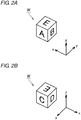
- Figs. 2A and 2B are views each illustrating one example of the workpiece W, which is an object to be inspected.
- the workpiece W is a cube.
- an E surface of the workpiece W is orthogonal to "an A surface” to "a D surface” of the workpiece W.
- the A surface of the workpiece W faces “the C surface” of the workpiece W.
- the B surface” of the workpiece W faces “the D surface” of the workpiece W.
- a shape of the workpiece W which is an object to be inspected, is not limited to a cube, but may be a polyhedron such as a rectangular parallelepiped, cylindrical, and another shape.
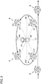
- Fig. 3 is a view illustrating a process in which the robot 200 is causing the workpiece W to circle around the omnidirectional camera 300.
- the omnidirectional camera 300 includes an omnidirectional mirror 331 and a capturing unit 332.
- the omnidirectional mirror 331 reflects light received from 360° around, and guides the reflected light to the capturing unit 332. This allows the omnidirectional camera 300 to capture an image 360° around.
- the robot 200 causes the workpiece W to circle around the omnidirectional camera 300 in the state where the posture of the workpiece W is maintained. At this time, since the posture of the workpiece W is maintained, the external appearance of the workpiece W when viewed from the omnidirectional camera 300 changes at each position of the workpiece W.
- a circling trajectory of the workpiece W is circular. That is, the robot 200 causes the workpiece W to circle around the omnidirectional camera 300 in a state where a constant distance is maintained from the omnidirectional camera 300 to the workpiece W. This allows, while the workpiece W is circling around the omnidirectional camera 300, the constant distance to be always maintained between the workpiece W and the omnidirectional camera 300. This results in a constant size of the workpiece W shown in an image obtained from the omnidirectional camera 300.
- the robot 200 does not stop the workpiece W while the workpiece W is circling around the omnidirectional camera 300. This enables continuous inspection of the workpiece W that is sequentially conveyed, without stopping the workpiece W. Since a circling process of the workpiece W is performed during a pick and place operation of the workpiece W, even if the circling process of the workpiece W is added, a tact time does not increase.
- the robot 200 While the robot 200 is causing the workpiece W to circle around, the robot 200 regularly transmits a position of the workpiece W (or a position of an arm) to the controller 100.
- the controller 100 determines that the robot 200 is causing the workpiece W to circle around the omnidirectional camera 300.
- the controller 100 outputs a capturing instruction to the omnidirectional camera 300 at a plurality of timings while the workpiece W is circling around the omnidirectional camera 300. This allows the omnidirectional camera 300 to capture the workpiece W from various directions.
- the controller 100 can acquire, from the omnidirectional camera 300, a plurality of input images indicating the workpiece W from different directions.
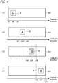
- Fig. 4 is a diagram illustrating one example of the input images obtained from the omnidirectional camera 300.
- the controller 100 outputs the capturing instruction to the omnidirectional camera 300 at timing t1.
- an input image 33A indicating "the D surface” of the workpiece W is obtained.
- the controller 100 outputs the capturing instruction to the omnidirectional camera 300 at timing t2.
- an input image 33B indicating "the A surface” of the workpiece W is obtained.
- the controller 100 outputs the capturing instruction to the omnidirectional camera 300 at timing t3.
- an input image 33C indicating "the B surface” of the workpiece W is obtained.
- the controller 100 outputs the capturing instruction to the omnidirectional camera 300 at timing t4.
- an input image 33D indicating "the C surface” of the workpiece W is obtained.
- the circling time and the capturing count may be set in advance, and may be set arbitrarily.
- the controller 100 can acquire, from one omnidirectional camera 300, the input images 30A to 30D indicating the workpiece W from different directions.
- Fig. 3 illustrates the example in which the workpiece W circles around the omnidirectional camera 300 in a full circle.
- the workpiece W does not necessarily have to circle around the omnidirectional camera 300 in a full circle. That is, the workpiece W is only required to circle around the omnidirectional camera 300 in at least part of a circle in the state where the posture is maintained. Also, the workpiece W does not need to circle around on a horizontal plane, and may circle around in any direction as long as the posture is maintained in part or all of a visual field of the omnidirectional camera 300.
- Fig. 5 is a diagram illustrating one example of a functional configuration of the controller 100.
- the controller 100 includes a processor 102 and a secondary storage device 108 as major hardware components.
- the processor 102 includes an acquisition unit 150, an identification unit 152, and an inspector 154 as functional components.
- Fig. 5 illustrates the example in which the acquisition unit 150, the identification unit 152, and the inspector 154 are mounted on the controller 100
- at least part of these functions may be mounted on another external device.
- at least part of these functions may be mounted on an external device such as the image sensor 51 (refer to Fig. 1 ) or a server.
- the controller 100 and the external device cooperate to implement various processes according to the embodiment.
- the following describes the acquisition unit 150, the identification unit 152, and the inspector 154 sequentially.
- the acquisition unit 150 outputs the capturing instruction to the omnidirectional camera 300 at a plurality of timings while the workpiece W is circling around the omnidirectional camera 300.
- the acquisition unit 150 then acquires, from the omnidirectional camera 300, the plurality of input images indicating the workpiece W from different directions. Since a method for capturing the workpiece W has been described in Fig. 3 , the method will not be described again.
- the robot 200 causes the workpiece W to circle around the omnidirectional camera 300 in the state where the posture of the workpiece W is maintained.
- a direction of the workpiece W changes when viewed from the omnidirectional camera 300.
- the direction of the workpiece W with respect to the omnidirectional camera 300 is also referred to as "a workpiece direction.” That is, the workpiece direction means an angle between a predetermined reference axis that passes on a circling plane and passes the center of the workpiece W, and a straight line connecting the workpiece W and the omnidirectional camera 300.
- the identification unit 152 identifies the direction of the workpiece W at a capturing timing of the workpiece W. Various methods are employed as the method for identifying the direction of the workpiece W. The method for identifying the direction of the workpiece W will be described below with reference to Figs. 6 to 9 .
- Fig. 6 is a diagram for describing a first identification method for identifying the direction of the workpiece W.
- Fig. 6 illustrates a position P1 of the omnidirectional camera 300, and a position P2 of the workpiece W at a predetermined timing at which the workpiece W is circling around the omnidirectional camera 300.
- the position P1 of the omnidirectional camera 300 is prescribed, for example, as a camera position 134 (refer to Fig. 5 ).
- the camera position 134 may be set when the omnidirectional camera 300 is installed, and may be arbitrarily set by a user.
- the camera position 134 may be represented, for example, as a coordinate value on an xy plane, and may be represented as a coordinate value on an xyz plane.
- the coordinate value represents, for example, the center of the omnidirectional camera 300.
- the position P2 of the workpiece W is acquired from the robot 200. More specifically, the controller 100 outputs, to the robot 200, a request for acquiring the position P2 of the workpiece W, simultaneously with outputting the capturing instruction of the workpiece W to the omnidirectional camera 300. This allows the controller 100 to acquire, from the robot 200, the position P2 of the workpiece W at the time of capturing the workpiece W.
- the position P2 of the workpiece W may be represented, for example, as a coordinate value on an xy plane, and may be represented as a coordinate value on an xyz plane.
- the coordinate value represents, for example, the center of the workpiece W.
- the identification unit 152 identifies a direction from the position P1 of the omnidirectional camera 300 to the position P2 of the workpiece W as a capturing direction of the workpiece W.
- the capturing direction corresponds to the direction of the workpiece W when viewed from the omnidirectional camera 300.
- the capturing direction corresponds to the direction of the workpiece W one-to-one. That is, the direction of the workpiece W is always identical at an identical point on the circling trajectory.
- the identification unit 152 identifies the direction of the workpiece W from the capturing direction of the workpiece W based on correspondence between the capturing direction of the workpiece W and the direction of the workpiece W.
- the identification unit 152 identifies the direction of the workpiece W for all the input images obtained from the omnidirectional camera 300 (for example, first and second input images). More specifically, the identification unit 152 identifies the direction of the workpiece W shown in the first input image based on the position of the workpiece W at the capturing timing of the first input image and the position of the omnidirectional camera 300. Similarly, the identification unit 152 identifies the direction of the workpiece W shown in the second input image based on the position of the workpiece W at the capturing timing of the second input image and the position of the omnidirectional camera 300.
- FIG. 7 is a diagram for describing a second identification method for identifying the direction of the workpiece W.
- Fig. 7 illustrates the input image 33B as one example of the input images obtained from the omnidirectional camera 300.
- a position in a long side direction of the input image 33B corresponds to a direction of a subject when viewed from the omnidirectional camera 300. That is, a coordinate value of the workpiece W in the input image 33B corresponds to the direction of the workpiece W one-to-one.
- the identification unit 152 identifies the direction of the workpiece W corresponding to the coordinate value of the workpiece W detected from the input image 33B. In the example of Fig. 7 , the identification unit 152 identifies "135°" corresponding to a central position P3 of the workpiece W as the direction of the workpiece W at the capturing timing of the input image 33B.
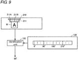
- FIG. 8 is a view illustrating a grip portion 210, which is a portion with which the robot 200 grips the workpiece W.
- Fig. 8 illustrates an enlarged view of the grip portion 210.
- Different marks are put at different positions on a surface of the grip portion 210.
- the marks serve as reference for identifying the direction of the workpiece W.
- Difference in the marks may be represented by difference in color, and may be represented by difference in shape.
- a scale 211 is put on the grip portion 210, and the scale 211 is represented by marks 211A and 211B with different color.
- a position where the mark is put is not limited to the grip portion 210, but the mark is put at any position of the robot 200 if the position is included in a visual field of the omnidirectional camera 300.
- Fig. 9 is a diagram for describing a third identification method for identifying the direction of the workpiece W.
- the identification unit 152 detects the grip portion 210 from an input image 38 obtained by capturing the workpiece W. Next, the identification unit 152 identifies a type of mark shown at the center or substantial center of the detected grip portion 210. Subsequently, with reference to mark information 128 that prescribes the direction of the workpiece W for each type of mark, the identification unit 152 identifies a direction associated with the identified mark as the direction of the workpiece W. In the example of Fig. 9 , "90°" associated with the mark 211B in the mark information 128 is identified as the direction of the workpiece W.
- the identification unit 152 identifies the direction of the workpiece W for all the input images obtained from the omnidirectional camera 300 (for example, first and second input images). More specifically, the identification unit 152 detects the mark shown in the first input image and identifies the direction associated with the detected mark in the mark information 128. The identification unit 152 then identifies the identified direction as the direction of the workpiece W shown in the first input image. Similarly, the identification unit 152 detects the mark shown in the second input image and identifies the direction associated with the detected mark in the mark information 128. The identification unit 152 then identifies the identified direction as the direction of the workpiece W shown in the second input image.
- the identification unit 152 can identify the direction of the workpiece W based on the direction of the workpiece W at the one point. Identifying the direction of the workpiece W at the one point is implemented, for example, by image processing such as template matching.
- the acquisition unit 150 outputs the capturing instruction to the omnidirectional camera 300 at a plurality of timings while the workpiece W is circling around the omnidirectional camera 300.
- the acquisition unit 150 then acquires, from the omnidirectional camera 300, the plurality of input images indicating the workpiece W from different directions.
- the inspector 154 inspects the workpiece W, which is an object to be inspected, using the plurality of input images acquired by the acquisition unit 150.
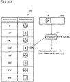
- FIG. 10 is a conceptual diagram schematically illustrating the inspection process of the workpiece W by the inspector 154.
- Fig. 10 illustrates the input image 33B acquired by capturing "the A surface" of the workpiece W as one example of the input image.
- the inspection process by the inspector 154 will be described below by citing, as an example, the input image 33B, which is one of the input images acquired from the acquisition unit 150.
- the inspector 154 inspects the workpiece W shown in the input image 33B with reference to reference image information 135.
- the reference image information 135 includes a plurality of reference images obtained by capturing in advance an object of a type identical to the object to be inspected. Each reference image is associated with a direction of the object shown in the reference image.
- the reference image information 135 is prepared in advance before the inspection process is executed. For example, the reference image information 135 is stored in advance in the secondary storage device 108 of the controller 100 (refer to Fig. 12 ).
- the identification unit 152 identifies the direction of the workpiece W shown in the input image 33B.
- the inspector 154 identifies the reference image associated with the direction of the workpiece W shown in the input image 33B with reference to the reference image information 135.
- a reference image 135A associated with the direction of the workpiece W "135°" is identified.
- the inspector 154 compares the identified reference image 135A with the input image 33B, and then inspects the workpiece W shown in the input image 33B based on a result of the comparison.
- the inspector 154 calculates a similarity group between each portion of the reference image 135A and the input image 33B while scanning the identified reference image 135A on the input image 33B.
- the inspector 154 then employs the maximum value of the similarity group as a similarity degree between the reference image 135A and the input image 33B.
- the similarity degree is represented, for example, by a correlated value between image information about the reference image 135A (for example, pixel value), and image information about the input image 33B (for example, pixel value).
- the inspector 154 determines that the external appearance of the workpiece W is normal.
- the inspector 154 determines that the external appearance of the workpiece W is abnormal.
- the inspector 154 performs such an inspection process on all the input images acquired from the acquisition unit 150 (for example, first and second input images). More specifically, the inspector 154 compares the reference image associated with the direction of the workpiece W shown in the first input image (first direction) with the first input image. Similarly, the inspector 154 compares the reference image associated with the direction of the workpiece W shown in the second input image (second direction) with the second input image. The inspector 154 inspects the workpiece W based on results of the comparison.
- the inspector 154 determines that the external appearance of the workpiece W is normal.
- the inspector 154 determines that the external appearance of the workpiece W is abnormal.
- the inspector 154 compares the cut portion with the reference image 135A. More specifically, when the omnidirectional camera 300 is used, a position where the workpiece W is shown in the input image 33B depends on a positional relationship between the workpiece W and the omnidirectional camera 300. Focusing on this point, the inspector 154 identifies the position of the object to be inspected shown in the input image 33B based on the positional relationship between the actual position of the workpiece W at the capturing timing of the input image 33B and the omnidirectional camera 300.
- the inspector 154 compares the workpiece W shown at the identified position with the reference image associated with the direction of the workpiece W, and then inspects the workpiece W based on a result of the comparison. Identifying a workpiece portion shown in the input image and then comparing the workpiece portion with the reference image makes the processing time required for the inspection process shorter than scanning the reference image 135A in the input image 33B.
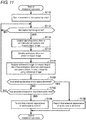
- Fig. 11 is a flowchart illustrating the inspection process by the controller 100.
- the process illustrated in Fig. 11 is implemented by the processor 102 of the controller 100 (refer to Fig. 5 ) executing a program. In other aspects, part or all of the process may be executed by a circuit element or other hardware.
- step S110 the processor 102 starts movement of the workpiece W by the robot 200 based on receipt of an instruction to execute the inspection process.
- the workpiece W circles around the omnidirectional camera 300 in the movement process.
- step S112 the processor 102 determines whether the capturing timing has come. As one example, the capturing timing comes at constant time intervals after the workpiece W reaches the circling trajectory of the omnidirectional camera 300. When the processor 102 determines that the capturing timing has come (YES in step S112), the processor 102 switches control to step S114. Otherwise (NO in step S112), the processor 102 executes the process of step S112 again.
- step S114 as the acquisition unit 150 (refer to Fig. 5 ), the processor 102 outputs the capturing instruction to the omnidirectional camera 300. The processor 102 then acquires the input image indicating the workpiece W from the omnidirectional camera 300.
- step S116 as the identification unit 152 (refer to Fig. 5 ), the processor 102 identifies the direction of the workpiece W shown in the input image acquired in step S114.
- the method for identifying the direction of the workpiece W has been described in Figs. 6 to Fig. 9 , and thus descriptions thereof will not be repeated.
- step S118 as the inspector 154 (refer to Fig. 5 ), the processor 102 acquires the reference image associated with the direction of the workpiece W identified in step S116 with reference to the reference image information 135 (refer to Fig. 10 ). The processor 102 then compares the reference image with the input image. The comparison process between the reference image and the input image has been described in Fig. 10 , and thus descriptions thereof will not be repeated.
- step S120 the processor 102 determines whether the external appearance of the workpiece W, which is an object to be inspected, is abnormal, based on a comparison result in step S118. As one example, the processor 102 determines that the external appearance of the workpiece W is abnormal when the similarity degree between the reference image and the input image is equal to or less than a value determined in advance. When the processor 102 determines that the external appearance of the workpiece W is abnormal (YES in step S120), the processor 102 switches control to step S130. Otherwise (NO in step S120), the processor 102 switches control to step S122.
- step S122 the processor 102 determines whether a prescribed inspection count has been performed on one workpiece W.
- the prescribed inspection count may be set in advance, and may be set arbitrarily.
- the prescribed inspection count corresponds to the capturing count on one workpiece W.
- the processor 102 switches control to step S124. Otherwise (NO in step S122), the processor 102 returns control to step S112.
- step S124 the processor 102 reports that the external appearance of the workpiece W is normal. Any method of the report may be used. As one example, the external appearance of the workpiece W being normal may be displayed as a message, and may be output as a sound.
- step S130 the processor 102 reports that the external appearance of the workpiece W is abnormal. Any method of the report may be used. As one example, the external appearance of the workpiece W being abnormal may be displayed as a message, and may be output as a sound.
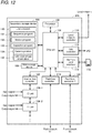
- FIG. 12 is a block diagram illustrating a hardware configuration example of the controller 100.
- the controller 100 includes the processor 102 such as a central processing unit (CPU) or a micro-processing unit (MPU), a chip set 104, a main storage device 106, and a secondary storage device 108.
- the controller 100 also includes a local network controller 110, a universal serial bus (USB) controller 112, a memory card interface 114, an internal bus controller 122, field bus controllers 118 and 120, and I/O units 124-1 and 124-2.
- the processor 102 such as a central processing unit (CPU) or a micro-processing unit (MPU), a chip set 104, a main storage device 106, and a secondary storage device 108.
- the controller 100 also includes a local network controller 110, a universal serial bus (USB) controller 112, a memory card interface 114, an internal bus controller 122, field bus controllers 118 and 120, and I/O units 124-1 and 124-2.
- USB universal serial bus
- the processor 102 reads various programs stored in the secondary storage device 108 and develops and executes the programs in the main storage device 106. Thus, the processor 102 implements control such as control according to an object to be controlled, and the inspection process.
- the chip set 104 controls the processor 102 and each component, thereby implementing process as the entire controller 100.
- a user program 130 to be executed using the PLC engine is stored in the secondary storage device 108. Furthermore, the camera position 134 (refer to Fig. 5 ), the reference image information 135, and other information are stored in the secondary storage device 108.
- the user program 130 includes a sequence program 131 that mainly performs logical calculations, and a motion program 132 that mainly performs numerical calculations such as position control and speed control.
- the user program 130 includes an inspection program 133 that mainly performs calculations for implementing the inspection process of the workpiece, and other programs.
- the local network controller 110 controls data exchange with other devices (for example, server) via a local network.
- the USB controller 112 controls data exchange with other devices (for example, personal computer (PC)) via USB connection.
- the memory card interface 114 is configured such that a memory card 116 is detachable.
- the memory card interface 114 can write data into the memory card 116 and read various types of data (such as user program and trace data) from the memory card 116.
- the internal bus controller 122 is an interface that exchanges data with the I/O units 124-1,124-2, and other I/O units mounted on the controller 100.
- the field bus controller 118 controls data exchange with other devices (for example, image sensor 51, counter 52) via the field network 54.
- the field bus controller 120 controls data exchange with other devices (for example, robot 200) via the field network 56.
- Fig. 12 illustrates the configuration example in which necessary functions are provided by the processor 102 executing the programs. However, part or all of these provided functions may be mounted using dedicated hardware circuitry (for example, application specific integrated circuit (ASIC) or a field-programmable gate array (FPGA)). Alternatively, main parts of the controller 100 may be implemented using hardware according to general-purpose architecture (for example, industrial personal computer based on a general-purpose personal computer). In this case, a plurality of operating systems (OSs) for different applications may be executed in parallel using virtual technique, and necessary applications may be executed on each OS.
- OSs operating systems
- the controller 100 instructs the robot 200 to cause the workpiece W to circle around the omnidirectional camera 300 in the state where the posture of the object to be inspected is maintained.
- the controller 100 outputs the capturing instruction to the omnidirectional camera 300 at a plurality of timings while the robot 200 is causing the workpiece W to circle around the omnidirectional camera 300.
- the plurality of input images indicating the workpiece W from different directions is obtained.
- the controller 100 inspects the workpiece W by using the plurality of input images.
- the controller 100 can acquire, from one omnidirectional camera 300, the input images 30A to 30D indicating the workpiece W from different directions.
- the robot 200 has caused the workpiece W to circle around the omnidirectional camera 300.
- a conveyor 200A causes a workpiece W to circle around an omnidirectional camera 300. This allows the omnidirectional camera 300 to capture a plurality of workpieces W simultaneously.
- Fig. 13 is a view illustrating how a conveyor 200A that serves as a movement device conveys workpieces W.
- Fig. 13 illustrates workpieces W1 to W6 as one example of objects to be inspected.
- the conveyor 200A causes the plurality of workpieces W1 to W6 to be simultaneously conveyed around the omnidirectional camera 300.
- the conveyor 200A causes the workpieces W1 to W6 to circle around the omnidirectional camera 300 in a state where postures of the workpieces W1 to W6 are maintained. Since the postures of the workpieces W1 to W6 are maintained, the external appearance of each workpiece when viewed from the omnidirectional camera 300 changes at each workpiece position.
- the controller 100 outputs a capturing instruction to the omnidirectional camera 300 at a plurality of timings while the workpieces W1 to W6 are circling around. This allows the omnidirectional camera 300 to capture the workpieces from various directions. As a result, the controller 100 can acquire a plurality of input images indicating the workpieces from different directions.
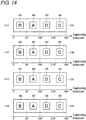
- Fig. 14 is a diagram illustrating one example of input images obtained from the omnidirectional camera 300 according to the second embodiment.
- the controller 100 outputs the capturing instruction to the omnidirectional camera 300 at timing t11.
- an input image 37A is obtained indicating "a C surface” of the workpiece W2, "a D surface” of the workpiece W3, “an A surface” of the workpiece W4, and "a B surface” of the workpiece W5. It is assumed that the controller 100 outputs the capturing instruction to the omnidirectional camera 300 at timing t12.
- an input image 37B is obtained indicating "the C surface” of the workpiece W3, “the D surface” of the workpiece W4, “the A surface” of the workpiece W5, and “the B surface” of the workpiece W6. It is assumed that the controller 100 outputs the capturing instruction to the omnidirectional camera 300 at timing t13.
- an input image 37C is obtained indicating "the C surface” of the workpiece W4, “the D surface” of the workpiece W5, “the A surface” of the workpiece W6, and “the B surface” of the workpiece W7. It is assumed that the controller 100 outputs the capturing instruction to the omnidirectional camera 300 at timing t14.
- an input image 37D is obtained indicating "the C surface” of the workpiece W5, “the D surface” of the workpiece W6, “the A surface” of the workpiece W7, and “the B surface” of the workpiece W8.
- the circling time and the capturing count may be set in advance, and may be set arbitrarily.
- the controller 100 can acquire, from one omnidirectional camera 300, the plurality of input images indicating each workpiece from different directions.
- the conveyor 200A conveys the workpieces such that each workpiece direction when the workpiece reaches the circling trajectory is always identical. As a result, as illustrated in Fig. 14 , the same surface of each workpiece is shown at the same position in the input images 37A to 37D.
- Fig. 13 illustrates the example in which the workpieces W1 to W6 circle around the omnidirectional camera 300 in a full circle
- the workpieces W1 to W6 do not necessarily have to circle around the omnidirectional camera 300 in a full circle. That is, the workpieces W1 to W6 are at least required to circle around the omnidirectional camera 300 in part of a circle in the state where the postures are maintained.
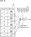
- FIG. 15 is a conceptual diagram schematically illustrating the inspection process of the workpiece according to the second embodiment.
- Fig. 15 illustrates, as one example of the input images, the input image 37A obtained by simultaneously capturing "the C surface” of the workpiece W2, "the D surface” of the workpiece W3, “the A surface” of the workpiece W4, and "the B surface” of the workpiece W5.
- the inspection process by the inspector 154 will be described below by citing, as an example, the input image 37A, which is one of the obtained input images.
- the identification unit 152 (refer to Fig. 5 ) identifies directions of the workpieces W2 to W5 shown in the input image 37A. As a method for identifying each workpiece direction, “the first to third identification methods" described in “the first embodiment” are employed. Each workpiece direction identified by the identification unit 152 is output to the inspector 154. In the example of Fig. 15 , “45°”, “135°”, “225°”, and “315°” are output to the inspector 154 as each workpiece direction.
- the inspector 154 inspects the workpieces W2 to W5 shown in the input image 37A with reference to the reference image information 135.
- the reference image information 135 includes a plurality of reference images obtained by capturing in advance an object of a type identical to an object to be inspected. Each reference image is associated with an object direction shown in the reference image.
- the reference image information 135 is prepared in advance before the inspection process is executed. For example, the reference image information 135 is stored in advance in a device such as the secondary storage device 108 of the controller 100 (refer to Fig. 12 ).
- the inspector 154 identifies the reference images corresponding to the directions of the workpieces W shown in the input image 37A with reference to the reference image information 135.
- a reference image 136A corresponding to a workpiece direction "45°” and a reference image 136B corresponding to a workpiece direction "135°” are identified.
- a reference image 136C corresponding to a workpiece direction "225°” and a reference image 136D corresponding to a workpiece direction "315°” are identified.
- the inspector 154 compares each of the identified reference images 136A to 136D with the input image 37A, and then inspects the workpieces W2 to W5 shown in the input image 37A based on a result of the comparison.
- the comparison process between the reference image and the input image has been described in Fig. 10 , and thus descriptions thereof will not be repeated.
- the inspector 154 executes the comparison process between the reference images and all of the plurality of input images acquired by the acquisition unit 150. Typically, the inspector 154 extracts the same workpiece from each input image, and then calculates a similarity degree between each extracted workpiece portion and the corresponding reference image. For example, when performing inspection on the workpiece W5, the inspector 154 performs the following calculations. The inspector 154 calculates the similarity degree between the workpiece W5 in the input image 37A and the reference image 136A. Also, the inspector 154 calculates the similarity degree between the workpiece W5 in the input image 37B (refer to Fig. 14 ) and the reference image 136B.
- the inspector 154 calculates the similarity degree between the workpiece W5 in the input image 37C (refer to Fig. 14 ) and the reference image 136C. Also, the inspector 154 calculates the similarity degree between the workpiece W5 in the input image 37D (refer to Fig. 14 ) and the reference image 136D. Then, when all the similarity degrees calculated about the workpiece W5 exceed a value determined in advance, the inspector 154 determines that the external appearance of the workpiece W5 is normal. On the other hand, when at least one of the similarity degrees calculated about the workpiece W5 is equal to or less than the value determined in advance, the inspector 154 determines that the external appearance of the workpiece W5 is abnormal.
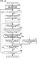
- FIG. 16 is a flowchart illustrating the inspection process by the controller 100 according to the second embodiment.
- the process illustrated in Fig. 16 is implemented by the processor 102 of the controller 100 (refer to Fig. 5 ) executing a program. In other aspects, part or all of the process may be executed by a circuit element or other hardware.
- step S210 the processor 102 starts conveyance of the workpiece by the conveyor 200A based on receipt of an instruction to execute the inspection process.
- the workpiece circles around the omnidirectional camera 300 in the conveyance process.
- step S220 the processor 102 determines whether the capturing timing has come.
- the capturing timing comes, for example, at constant time intervals.
- the processor 102 switches control to step S222. Otherwise (NO in step S220), the processor 102 executes the process of step S220 again.
- step S222 as the acquisition unit 150 (refer to Fig. 5 ), the processor 102 outputs the capturing instruction to the omnidirectional camera 300. The processor 102 then acquires the input image indicating the workpiece from the omnidirectional camera 300.
- step S224 the processor 102 detects the workpiece from the input image acquired in step S222.
- the processor 102 grasps each workpiece position on the conveyor 200A by a tracking process.
- the position of each workpiece on the conveyor 200A corresponds to the position of each workpiece in the input image. Therefore, the processor 102 can identify the position of each workpiece in the input image from the position of each workpiece on the conveyor 200A identified by the tracking process.
- the processor 102 may identify the workpiece position in the input image by using an image processing technology such as template matching.
- step S226 as the identification unit 152 (refer to Fig. 5 ), the processor 102 determines any one uninspected workpiece from the workpiece detected in step S224 as the workpiece to be inspected. The processor 102 then identifies the direction of the workpiece to be inspected. As a method for identifying the workpiece direction, "the first to third identification methods" described in "the first embodiment" are employed.
- step S230 the processor 102 determines whether the external appearance of the workpiece, which is an object to be inspected, is abnormal, based on a result of the comparison in step S228. As one example, the processor 102 determines that the external appearance of the workpiece to be inspected is abnormal when the similarity degree between the reference image and the input image is equal to or less than a value determined in advance. When the processor 102 determines that the external appearance of the workpiece to be inspected is abnormal (YES in step S230), the processor 102 switches control to step S234. Otherwise (NO in step S230), the processor 102 switches control to step S232.
- step S232 the processor 102 reports that the external appearance of the workpiece to be inspected is normal. Any method of the report may be used. As one example, the external appearance of the workpiece being normal may be displayed as a message, and may be output as a sound.
- step S234 the processor 102 reports that the external appearance of the workpiece to be inspected is abnormal. Any method of the report may be used. As one example, the external appearance of the workpiece being abnormal may be displayed as a message, and may be output as a sound.
- step S240 the processor 102 determines whether inspection of all the workpieces detected in step S224 has ended.
- the processor 102 determines that inspection of all the workpieces detected in step S224 has ended (YES in step S240)
- the processor 102 switches control to step S250. Otherwise (NO in step S240), the processor 102 returns control to step S226.
- step S250 the processor 102 determines whether to end the inspection process. As one example, when the processor 102 receives an operation to end the inspection process, the processor 102 determines to end the inspection process. When the processor 102 determines to end the inspection process (YES in step S250), the processor 102 ends the inspection process illustrated in Fig. 16 . Otherwise (NO in step S250), the processor 102 returns control to step S220.
- the conveyor 200A causes the workpieces, which are objects to be inspected, to circle around the omnidirectional camera 300. This allows the omnidirectional camera 300 to capture the plurality of workpieces simultaneously, and to inspect the plurality of workpieces simultaneously.
- the conveyor 200A causes each workpiece to circle around the omnidirectional camera 300 in a state where the posture of the workpiece is maintained.
- the controller 100 outputs the capturing instruction to the omnidirectional camera 300 at a plurality of timings while the workpiece is circling around. This allows the omnidirectional camera 300 to capture each workpiece from various directions. As a result, for each workpiece, the controller 100 can acquire the plurality of input images indicating the workpiece from different directions.
- a shape of a workpiece W which is an object to be inspected
- a shape of a workpiece W which is an object to be inspected
- a shape of a workpiece W which is an object to be inspected
- the controller 100 does not identify a workpiece direction when the shape of the object to be inspected is cylindrical. This shortens processing time.
- Fig. 17 is a view illustrating a process in which a robot 200 according to the third embodiment causes the workpiece W to circle around an omnidirectional camera 300.
- the shape of the workpiece W is cylindrical.
- the controller 100 outputs a capturing instruction to the omnidirectional camera 300 at a plurality of timings while the workpiece W is circling around the omnidirectional camera 300. This allows the omnidirectional camera 300 to capture the workpiece W from various directions. As a result, the controller 100 can acquire, from the omnidirectional camera 300, a plurality of input images indicating the workpiece W from different directions.
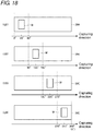
- Fig. 18 is a diagram illustrating one example of input images obtained from the omnidirectional camera 300 according to the third embodiment.
- the controller 100 outputs the capturing instruction to the omnidirectional camera 300 at timing t21.
- an input image 39A is obtained.
- the controller 100 outputs the capturing instruction to the omnidirectional camera 300 at timing t22.
- an input image 39B is obtained.
- the controller 100 outputs the capturing instruction to the omnidirectional camera 300 at timing t23.
- an input image 39C is obtained.
- the controller 100 outputs the capturing instruction to the omnidirectional camera 300 at timing t24.
- an input image 39D is obtained.
- the controller 100 does not need to identify the workpiece direction shown in the input images. Also, in the embodiment, it is not necessary to prepare the reference image for each direction of the workpiece W, and it is sufficient if at least one reference image is prepared.
- the controller 100 compares each of the input images obtained by capturing the workpiece W from various directions with the reference image prepared in advance, and then inspects the workpiece W based on a result of the comparison. This allows the controller 100 to inspect the cylindrical workpiece W from every direction.
- the controller 100 does not identify the workpiece direction, when the shape of the object to be inspected is cylindrical. This shortens processing time.
- the robot 200 has caused the workpiece W to circle around the omnidirectional camera 300 in a circle.
- a robot 200 causes a workpiece W to circle around an omnidirectional camera 300 in a square.
- Fig. 19 is a view illustrating how the robot 200 causes the workpiece W to circle around the omnidirectional camera 300 in a square.
- a circling trajectory of the workpiece W is not limited to circular.
- the circling trajectory of the workpiece W is arbitrary.
- the circling trajectory of the workpiece W may be elliptical, rectangular, or any other shapes.
Landscapes
- Engineering & Computer Science (AREA)
- General Physics & Mathematics (AREA)
- Physics & Mathematics (AREA)
- Theoretical Computer Science (AREA)
- Computer Vision & Pattern Recognition (AREA)
- Multimedia (AREA)
- Signal Processing (AREA)
- Quality & Reliability (AREA)
- Health & Medical Sciences (AREA)
- General Health & Medical Sciences (AREA)
- Analytical Chemistry (AREA)
- Immunology (AREA)
- Pathology (AREA)
- Chemical & Material Sciences (AREA)
- Life Sciences & Earth Sciences (AREA)
- Biochemistry (AREA)
- Robotics (AREA)
- Mechanical Engineering (AREA)
- Image Analysis (AREA)
- Investigating Materials By The Use Of Optical Means Adapted For Particular Applications (AREA)
- Image Processing (AREA)
Abstract
Description
- This application is based on Japanese Patent Application No.
2017-008255 - The present disclosure relates to a technology for inspecting an object to be inspected by using an omnidirectional camera.
- In a factory automation (FA) field, a technology for inspecting an external appearance of an object to be inspected by using a camera has been developed. Regarding this technology,
JP 2000-180382 A - Patent Document 1:
JP 2000-180382 A - The visual inspection device disclosed in
Patent Document 1 needs to include a plurality of cameras in order to capture an object to be inspected from various directions. This leads to high costs of the visual inspection device and a complicated configuration of the visual inspection device. Therefore, a technology for inspecting an external appearance of an object to be inspected from various directions with one camera is desired. - According to an aspect, an inspection system for inspecting an object to be inspected includes: an omnidirectional camera; a movement device configured to cause the object to be inspected to circle around the omnidirectional camera in a state where a posture of the object to be inspected is maintained; an acquisition unit configured to output a capturing instruction to the omnidirectional camera at a plurality of timings while the movement device causes the object to be inspected to circle around the omnidirectional camera, the acquisition unit being configured to acquire, from the omnidirectional camera, a plurality of input images indicating the object to be inspected from different directions; and an inspector configured to inspect the object to be inspected by using the plurality of input images.
- Preferably, the movement device causes the object to be inspected to circle around the omnidirectional camera in a state where a constant distance is maintained from the omnidirectional camera to the object to be inspected.
- Preferably, the movement device does not stop the object to be inspected while the object to be inspected is circling around the omnidirectional camera.
- Preferably, the inspection system further includes: a storage configured to associate and store a reference image obtained by capturing in advance an object of a type identical to the object to be inspected from a different direction with a direction of the object shown in the reference image; and an identification unit configured to identify a first direction of the object to be inspected shown in a first input image of the plurality of input images and a second direction of the object to be inspected shown in a second input image of the plurality of input images. The inspector compares the reference image associated with the first direction with the first input image, compares the reference image associated with the second direction with the second input image, and inspects the object to be inspected based on a result of the comparison.
- Preferably, the identification unit identifies the first direction based on a position of the object to be inspected at a capturing timing of the first input image, and a position of the omnidirectional camera, and identifies the second direction based on a position of the object to be inspected at a capturing timing of the second input image, and the position of the omnidirectional camera.
- Preferably, different marks are put at different positions on a surface of the movement device. The plurality of marks are associated in advance with directions of the object to be inspected. The identification unit identifies each of the directions associated with each of the marks shown in the first input image as the first direction, and identifies each of the directions associated with each of the marks shown in the second input image as the second direction.
- Preferably, the inspector: identifies the position of the object to be inspected shown in the first input image based on a positional relationship between the position of the object to be inspected at the capturing timing of the first input image and the omnidirectional camera, the inspector comparing the object to be inspected shown at the position with the reference image associated with the first direction; identifies the position of the object to be inspected shown in the second input image based on a positional relationship between the position of the object to be inspected at the capturing timing of the second input image and the omnidirectional camera, the inspector comparing the object to be inspected shown at the position with the reference image associated with the second direction; and inspects the object to be inspected based on a result of the comparison.
- According to another aspect, a controller for controlling a movement device for moving an object to be inspected and an omnidirectional camera for capturing the object to be inspected includes: an acquisition unit configured to output, to the movement device, an instruction for causing the object to be inspected to circle around the omnidirectional camera in a state where a posture of the object to be inspected is maintained, to output a capturing instruction to the omnidirectional camera at a plurality of timings while the movement device causes the object to be inspected to circle around the omnidirectional camera, and to acquire, from the omnidirectional camera, a plurality of input images indicating the object to be inspected from different directions; and an inspector configured to inspect the object to be inspected by using the plurality of input images.
- According to another aspect, an inspection method for inspecting an object to be inspected includes: causing the object to be inspected to circle around an omnidirectional camera in a state where a posture of the object to be inspected is maintained; outputting a capturing instruction to the omnidirectional camera at a plurality of timings while the object to be inspected is circling around the omnidirectional camera, and acquiring, from the omnidirectional camera, a plurality of input images indicating the object to be inspected from different directions; and inspecting the object to be inspected by using the plurality of input images.
- According to another aspect, a non-transitory computer-readable storage medium storing an inspection program for inspecting an object to be inspected, the inspection program causing a computer to execute: causing the object to be inspected to circle around an omnidirectional camera in a state where a posture of the object to be inspected is maintained; outputting a capturing instruction to the omnidirectional camera at a plurality of timings while the object to be inspected is circling around the omnidirectional camera, and acquiring, from the omnidirectional camera, a plurality of input images indicating the object to be inspected from different directions; and inspecting the object to be inspected by using the plurality of input images.
- In one aspect, an external appearance of an object to be inspected can be inspected from various directions with one camera.
- The above and additional objects, features, aspects, and advantages of the present disclosure will become apparent in the following detailed description regarding the present invention that will be understood in relation to accompanying drawings.
-
-
Fig. 1 is a schematic view illustrating a basic configuration of an inspection system according to a first embodiment; -
Figs. 2A and 2B are views each illustrating one example of a workpiece, which is an object to be inspected; -
Fig. 3 is a view illustrating a process in which a robot according to the first embodiment is causing the workpiece to circle around an omnidirectional camera; -
Fig. 4 is a diagram illustrating one example of input images obtained from the omnidirectional camera according to the first embodiment; -
Fig. 5 is a diagram illustrating one example of a functional configuration of a controller according to the first embodiment; -
Fig. 6 is a diagram for describing a first identification method for identifying a direction of the workpiece; -
Fig. 7 is a diagram for describing a second identification method for identifying the direction of the workpiece; -
Fig. 8 is a view illustrating agrip portion 210, which is a portion with which the robot according to the first embodiment grips the workpiece; -
Fig. 9 is a diagram for describing a third identification method for identifying the direction of the workpiece; -
Fig. 10 is a conceptual diagram schematically illustrating an inspection process of the workpiece by an inspector; -
Fig. 11 is a flowchart illustrating the inspection process by the controller according to the first embodiment; -
Fig. 12 is a block diagram illustrating a hardware configuration example of the controller according to the first embodiment; -
Fig. 13 is a view illustrating how a conveyor that serves as a movement device conveys workpieces W; -
Fig. 14 is a diagram illustrating one example of input images obtained from an omnidirectional camera according to a second embodiment; -
Fig. 15 is a conceptual diagram schematically illustrating an inspection process of a workpiece according to the second embodiment; -
Fig. 16 is a flowchart illustrating an inspection process by a controller according to the second embodiment; -
Fig. 17 is a view illustrating a process in which a robot according to a third embodiment causes a workpiece to circle around an omnidirectional camera; -
Fig. 18 is a diagram illustrating one example of input images obtained from the omnidirectional camera according to the third embodiment; and -
Fig. 19 is a view illustrating how a robot according to a fourth embodiment causes a workpiece to circle around an omnidirectional camera in a square. - Embodiments according to the present invention will be described below with reference to the drawings. In the following description, the same component and constituent element are denoted with the same reference symbol. A name and function thereof are the same. Therefore, detailed descriptions thereof will not be repeated.
- With reference to
Fig. 1 , a basic configuration of aninspection system 1 according to the embodiment will be described.Fig. 1 is a schematic view illustrating a basic configuration of aninspection system 1 according to the embodiment. - As illustrated in
Fig. 1 , theinspection system 1 includes, for example, acontroller 100, arobot 200 that serves as a movement device, and anomnidirectional camera 300. - The
controller 100 is, for example, a programmable logic controller (PLC), and controls theentire inspection system 1. As one example, thecontroller 100 controls devices such as animage sensor 51, therobot 200, and theomnidirectional camera 300. - The
controller 100 is connected, for example, to afield network 54 in a daisy chain with theimage sensor 51 and acounter 52. As thefield network 54, for example, EtherCAT (registered trademark) is employed. Thecontroller 100 has a communication linkage with therobot 200 via afield network 56. As thefield network 56, for example, EtherNET (registered trademark) is employed. - The
inspection system 1 performs predetermined work on a workpiece W (object to be inspected) conveyed on aconveyor 20A. The workpiece W is a product or semi-finished product, and for example, may be an electronic component or a food. - The
image sensor 51 regularly captures theconveyor 20A and detects the workpiece W from an obtained input image. As one example, theimage sensor 51 detects the workpiece W by image processing such as template matching. A coordinate value of the workpiece W in the input image is output to thecontroller 100. - The
counter 52 measures a movement amount of theconveyor 20A based on a pulse wave generated from anencoder 53. More specifically, theencoder 53 generates a pulse signal according to the movement amount of theconveyor 20A. Thecounter 52 receives the pulse signal from theencoder 53 and counts the number of pulses included in the pulse signal to measure the movement amount of theconveyor 20A. Thecounter 52 then transmits a counted value of the pulse wave to thecontroller 100 at constant communication intervals. - The
controller 100 substitutes the coordinate value (camera coordinate system) of the workpiece W in the input image received from theimage sensor 51 into a coordinate transformation equation determined in advance. Thecontroller 100 then transforms the coordinate value of the workpiece W of the camera coordinate system into a coordinate value of a world coordinate system. The world coordinate system is a coordinate system for controlling therobot 200. Every time thecontroller 100 receives the counted value from thecounter 52, thecontroller 100 calculates the movement amount from last time on theconveyor 20A. Thecontroller 100 then adds the movement amount to the coordinate value of the workpiece W indicated in the world coordinate system. The movement amount of theconveyor 20A corresponding to one count is set in advance. Thecontroller 100 can track the workpiece W conveyed on theconveyor 20A by sequentially updating the coordinate value of the workpiece W indicated in the world coordinate system. - Based on the workpiece W having reached a range determined in advance on the
conveyor 20A, thecontroller 100 sends a workpiece W pickup instruction to therobot 200. At this time, thecontroller 100 sequentially sends, to therobot 200, the coordinate value of the workpiece W on theconveyor 20A. This allows therobot 200 to grasp a current position of the workpiece W and to pick up the workpiece W on theconveyor 20A. - Subsequently, the
robot 200 causes the workpiece W to circle around theomnidirectional camera 300 in a state where a posture of the workpiece W is maintained, and then therobot 200 moves the workpiece W to aconveyor 20B. "The state where the posture of the workpiece W is maintained" means a state where the workpiece W is fixed so as to prevent the workpiece W from rotating. This is a state where each surface of the workpiece W is always in the same direction during a circling process. Thecontroller 100 captures the workpiece W while the workpiece W is circling around theomnidirectional camera 300. Thecontroller 100 then inspects an external appearance of the workpiece W by using the input image obtained as a result of the capturing. Details of the inspection process will be described later. - Note that although
Fig. 1 illustrates the example in which theinspection system 1 includes onecontroller 100, theinspection system 1 may include a plurality ofcontrollers 100. Also, althoughFig. 1 illustrates the example in which theinspection system 1 includes onerobot 200, theinspection system 1 may include a plurality ofrobots 200. Also, althoughFig. 1 illustrates the example in which theinspection system 1 includes oneomnidirectional camera 300, theinspection system 1 may include a plurality ofomnidirectional cameras 300. - With reference to
Figs. 2 to 4 , a workpiece W capturing process by theomnidirectional camera 300 will be described. -
Figs. 2A and 2B are views each illustrating one example of the workpiece W, which is an object to be inspected. For convenience of describing a direction of the workpiece W, the following description assumes that the workpiece W is a cube. As illustrated inFig. 2 , it is assumed that "an E surface" of the workpiece W is orthogonal to "an A surface" to "a D surface" of the workpiece W. It is assumed that "the A surface" of the workpiece W faces "the C surface" of the workpiece W. It is assumed that "the B surface" of the workpiece W faces "the D surface" of the workpiece W. - Note that a shape of the workpiece W, which is an object to be inspected, is not limited to a cube, but may be a polyhedron such as a rectangular parallelepiped, cylindrical, and another shape.
-
Fig. 3 is a view illustrating a process in which therobot 200 is causing the workpiece W to circle around theomnidirectional camera 300. - The
omnidirectional camera 300 includes anomnidirectional mirror 331 and acapturing unit 332. Theomnidirectional mirror 331 reflects light received from 360° around, and guides the reflected light to thecapturing unit 332. This allows theomnidirectional camera 300 to capture an image 360° around. - As described above, the
robot 200 causes the workpiece W to circle around theomnidirectional camera 300 in the state where the posture of the workpiece W is maintained. At this time, since the posture of the workpiece W is maintained, the external appearance of the workpiece W when viewed from theomnidirectional camera 300 changes at each position of the workpiece W. - Typically, a circling trajectory of the workpiece W is circular. That is, the
robot 200 causes the workpiece W to circle around theomnidirectional camera 300 in a state where a constant distance is maintained from theomnidirectional camera 300 to the workpiece W. This allows, while the workpiece W is circling around theomnidirectional camera 300, the constant distance to be always maintained between the workpiece W and theomnidirectional camera 300. This results in a constant size of the workpiece W shown in an image obtained from theomnidirectional camera 300. - Typically, the
robot 200 does not stop the workpiece W while the workpiece W is circling around theomnidirectional camera 300. This enables continuous inspection of the workpiece W that is sequentially conveyed, without stopping the workpiece W. Since a circling process of the workpiece W is performed during a pick and place operation of the workpiece W, even if the circling process of the workpiece W is added, a tact time does not increase. - While the
robot 200 is causing the workpiece W to circle around, therobot 200 regularly transmits a position of the workpiece W (or a position of an arm) to thecontroller 100. When the received position of the workpiece W is on the circling trajectory determined in advance, thecontroller 100 determines that therobot 200 is causing the workpiece W to circle around theomnidirectional camera 300. Thecontroller 100 outputs a capturing instruction to theomnidirectional camera 300 at a plurality of timings while the workpiece W is circling around theomnidirectional camera 300. This allows theomnidirectional camera 300 to capture the workpiece W from various directions. As a result, thecontroller 100 can acquire, from theomnidirectional camera 300, a plurality of input images indicating the workpiece W from different directions. -
Fig. 4 is a diagram illustrating one example of the input images obtained from theomnidirectional camera 300. As one example, it is assumed that thecontroller 100 outputs the capturing instruction to theomnidirectional camera 300 at timing t1. As a result, aninput image 33A indicating "the D surface" of the workpiece W is obtained. Similarly, it is assumed that thecontroller 100 outputs the capturing instruction to theomnidirectional camera 300 at timing t2. As a result, aninput image 33B indicating "the A surface" of the workpiece W is obtained. Similarly, it is assumed that thecontroller 100 outputs the capturing instruction to theomnidirectional camera 300 at timing t3. As a result, aninput image 33C indicating "the B surface" of the workpiece W is obtained. Similarly, it is assumed that thecontroller 100 outputs the capturing instruction to theomnidirectional camera 300 at timing t4. As a result, aninput image 33D indicating "the C surface" of the workpiece W is obtained. - Intervals at which the capturing instruction is output are calculated by, for example, dividing, by a capturing count, a circling time needed for the workpiece W to circle around the
omnidirectional camera 300 in a full circle. For example, when the circling time is one second and the capturing count is four times, the capturing interval will be 0.25 seconds (= 1/4). The circling time and the capturing count may be set in advance, and may be set arbitrarily. - Thus, by outputting the capturing instruction to the
omnidirectional camera 300 at different timings while the workpiece W is circling around, thecontroller 100 can acquire, from oneomnidirectional camera 300, the input images 30A to 30D indicating the workpiece W from different directions. - Note that
Fig. 3 illustrates the example in which the workpiece W circles around theomnidirectional camera 300 in a full circle. However, the workpiece W does not necessarily have to circle around theomnidirectional camera 300 in a full circle. That is, the workpiece W is only required to circle around theomnidirectional camera 300 in at least part of a circle in the state where the posture is maintained. Also, the workpiece W does not need to circle around on a horizontal plane, and may circle around in any direction as long as the posture is maintained in part or all of a visual field of theomnidirectional camera 300. - Functions of the
controller 100 will be described with reference toFigs. 5 to 10 . -
Fig. 5 is a diagram illustrating one example of a functional configuration of thecontroller 100. As illustrated inFig. 5 , thecontroller 100 includes aprocessor 102 and asecondary storage device 108 as major hardware components. Theprocessor 102 includes anacquisition unit 150, anidentification unit 152, and aninspector 154 as functional components. - Note that although
Fig. 5 illustrates the example in which theacquisition unit 150, theidentification unit 152, and theinspector 154 are mounted on thecontroller 100, at least part of these functions may be mounted on another external device. For example, at least part of these functions may be mounted on an external device such as the image sensor 51 (refer toFig. 1 ) or a server. In this case, thecontroller 100 and the external device cooperate to implement various processes according to the embodiment. - The following describes the
acquisition unit 150, theidentification unit 152, and theinspector 154 sequentially. - The
acquisition unit 150 outputs the capturing instruction to theomnidirectional camera 300 at a plurality of timings while the workpiece W is circling around theomnidirectional camera 300. Theacquisition unit 150 then acquires, from theomnidirectional camera 300, the plurality of input images indicating the workpiece W from different directions. Since a method for capturing the workpiece W has been described inFig. 3 , the method will not be described again. - As described above, the
robot 200 causes the workpiece W to circle around theomnidirectional camera 300 in the state where the posture of the workpiece W is maintained. At this time, although the workpiece W itself does not rotate, a direction of the workpiece W changes when viewed from theomnidirectional camera 300. Hereinafter, the direction of the workpiece W with respect to theomnidirectional camera 300 is also referred to as "a workpiece direction." That is, the workpiece direction means an angle between a predetermined reference axis that passes on a circling plane and passes the center of the workpiece W, and a straight line connecting the workpiece W and theomnidirectional camera 300. - The
identification unit 152 identifies the direction of the workpiece W at a capturing timing of the workpiece W. Various methods are employed as the method for identifying the direction of the workpiece W. The method for identifying the direction of the workpiece W will be described below with reference toFigs. 6 to 9 . -
Fig. 6 is a diagram for describing a first identification method for identifying the direction of the workpiece W.Fig. 6 illustrates a position P1 of theomnidirectional camera 300, and a position P2 of the workpiece W at a predetermined timing at which the workpiece W is circling around theomnidirectional camera 300. - The position P1 of the
omnidirectional camera 300 is prescribed, for example, as a camera position 134 (refer toFig. 5 ). Thecamera position 134 may be set when theomnidirectional camera 300 is installed, and may be arbitrarily set by a user. Thecamera position 134 may be represented, for example, as a coordinate value on an xy plane, and may be represented as a coordinate value on an xyz plane. The coordinate value represents, for example, the center of theomnidirectional camera 300. - The position P2 of the workpiece W is acquired from the
robot 200. More specifically, thecontroller 100 outputs, to therobot 200, a request for acquiring the position P2 of the workpiece W, simultaneously with outputting the capturing instruction of the workpiece W to theomnidirectional camera 300. This allows thecontroller 100 to acquire, from therobot 200, the position P2 of the workpiece W at the time of capturing the workpiece W. The position P2 of the workpiece W may be represented, for example, as a coordinate value on an xy plane, and may be represented as a coordinate value on an xyz plane. The coordinate value represents, for example, the center of the workpiece W. - The
identification unit 152 identifies a direction from the position P1 of theomnidirectional camera 300 to the position P2 of the workpiece W as a capturing direction of the workpiece W. The capturing direction corresponds to the direction of the workpiece W when viewed from theomnidirectional camera 300. In a case where the direction of the workpiece W when the workpiece W reaches the circling trajectory is always identical, the capturing direction corresponds to the direction of the workpiece W one-to-one. That is, the direction of the workpiece W is always identical at an identical point on the circling trajectory. Theidentification unit 152 identifies the direction of the workpiece W from the capturing direction of the workpiece W based on correspondence between the capturing direction of the workpiece W and the direction of the workpiece W. - The
identification unit 152 identifies the direction of the workpiece W for all the input images obtained from the omnidirectional camera 300 (for example, first and second input images). More specifically, theidentification unit 152 identifies the direction of the workpiece W shown in the first input image based on the position of the workpiece W at the capturing timing of the first input image and the position of theomnidirectional camera 300. Similarly, theidentification unit 152 identifies the direction of the workpiece W shown in the second input image based on the position of the workpiece W at the capturing timing of the second input image and the position of theomnidirectional camera 300. - Next, with reference to
Fig. 7 , another method for identifying the direction of the workpiece W will be described.Fig. 7 is a diagram for describing a second identification method for identifying the direction of the workpiece W. -
Fig. 7 illustrates theinput image 33B as one example of the input images obtained from theomnidirectional camera 300. When theomnidirectional camera 300 is used, a position in a long side direction of theinput image 33B corresponds to a direction of a subject when viewed from theomnidirectional camera 300. That is, a coordinate value of the workpiece W in theinput image 33B corresponds to the direction of the workpiece W one-to-one. Focusing on this point, based on correspondence between the coordinate value of the workpiece W in the input image and the direction of the workpiece W, theidentification unit 152 identifies the direction of the workpiece W corresponding to the coordinate value of the workpiece W detected from theinput image 33B. In the example ofFig. 7 , theidentification unit 152 identifies "135°" corresponding to a central position P3 of the workpiece W as the direction of the workpiece W at the capturing timing of theinput image 33B. - Next, with reference to
Figs. 8 and9 , another method for identifying the direction of the workpiece W will be described.Fig. 8 is a view illustrating agrip portion 210, which is a portion with which therobot 200 grips the workpiece W. -
Fig. 8 illustrates an enlarged view of thegrip portion 210. Different marks are put at different positions on a surface of thegrip portion 210. The marks serve as reference for identifying the direction of the workpiece W. Difference in the marks may be represented by difference in color, and may be represented by difference in shape. In the example ofFig. 8 , ascale 211 is put on thegrip portion 210, and thescale 211 is represented bymarks - Note that a position where the mark is put is not limited to the
grip portion 210, but the mark is put at any position of therobot 200 if the position is included in a visual field of theomnidirectional camera 300. -
Fig. 9 is a diagram for describing a third identification method for identifying the direction of the workpiece W. Theidentification unit 152 detects thegrip portion 210 from an input image 38 obtained by capturing the workpiece W. Next, theidentification unit 152 identifies a type of mark shown at the center or substantial center of the detectedgrip portion 210. Subsequently, with reference to markinformation 128 that prescribes the direction of the workpiece W for each type of mark, theidentification unit 152 identifies a direction associated with the identified mark as the direction of the workpiece W. In the example ofFig. 9 , "90°" associated with themark 211B in themark information 128 is identified as the direction of the workpiece W. - The
identification unit 152 identifies the direction of the workpiece W for all the input images obtained from the omnidirectional camera 300 (for example, first and second input images). More specifically, theidentification unit 152 detects the mark shown in the first input image and identifies the direction associated with the detected mark in themark information 128. Theidentification unit 152 then identifies the identified direction as the direction of the workpiece W shown in the first input image. Similarly, theidentification unit 152 detects the mark shown in the second input image and identifies the direction associated with the detected mark in themark information 128. Theidentification unit 152 then identifies the identified direction as the direction of the workpiece W shown in the second input image. - Note that the above description assumes that the direction of the workpiece W when the workpiece W reaches the circling trajectory is always identical. However, the direction of the workpiece W when the workpiece W reaches the circling trajectory does not always need to be identical. Even if the direction of the workpiece W at the time is not always identical, if the direction of the workpiece W at one point on the circling trajectory is detected, the
identification unit 152 can identify the direction of the workpiece W based on the direction of the workpiece W at the one point. Identifying the direction of the workpiece W at the one point is implemented, for example, by image processing such as template matching. - As described above, the
acquisition unit 150 outputs the capturing instruction to theomnidirectional camera 300 at a plurality of timings while the workpiece W is circling around theomnidirectional camera 300. Theacquisition unit 150 then acquires, from theomnidirectional camera 300, the plurality of input images indicating the workpiece W from different directions. Theinspector 154 inspects the workpiece W, which is an object to be inspected, using the plurality of input images acquired by theacquisition unit 150. - With reference to
Fig. 10 , an inspection process of the workpiece W by theinspector 154 will be described.Fig. 10 is a conceptual diagram schematically illustrating the inspection process of the workpiece W by theinspector 154. -
Fig. 10 illustrates theinput image 33B acquired by capturing "the A surface" of the workpiece W as one example of the input image. The inspection process by theinspector 154 will be described below by citing, as an example, theinput image 33B, which is one of the input images acquired from theacquisition unit 150. - The
inspector 154 inspects the workpiece W shown in theinput image 33B with reference toreference image information 135. Thereference image information 135 includes a plurality of reference images obtained by capturing in advance an object of a type identical to the object to be inspected. Each reference image is associated with a direction of the object shown in the reference image. Thereference image information 135 is prepared in advance before the inspection process is executed. For example, thereference image information 135 is stored in advance in thesecondary storage device 108 of the controller 100 (refer toFig. 12 ). - As described above, the
identification unit 152 identifies the direction of the workpiece W shown in theinput image 33B. Theinspector 154 identifies the reference image associated with the direction of the workpiece W shown in theinput image 33B with reference to thereference image information 135. In the example ofFig. 10 , a reference image 135A associated with the direction of the workpiece W "135°" is identified. Theinspector 154 compares the identified reference image 135A with theinput image 33B, and then inspects the workpiece W shown in theinput image 33B based on a result of the comparison. - Typically, the
inspector 154 calculates a similarity group between each portion of the reference image 135A and theinput image 33B while scanning the identified reference image 135A on theinput image 33B. Theinspector 154 then employs the maximum value of the similarity group as a similarity degree between the reference image 135A and theinput image 33B. The similarity degree is represented, for example, by a correlated value between image information about the reference image 135A (for example, pixel value), and image information about theinput image 33B (for example, pixel value). When the calculated similarity degree exceeds a value determined in advance, theinspector 154 determines that the external appearance of the workpiece W is normal. On the other hand, when the calculated similarity degree is equal to or less than the value determined in advance, theinspector 154 determines that the external appearance of the workpiece W is abnormal. - The
inspector 154 performs such an inspection process on all the input images acquired from the acquisition unit 150 (for example, first and second input images). More specifically, theinspector 154 compares the reference image associated with the direction of the workpiece W shown in the first input image (first direction) with the first input image. Similarly, theinspector 154 compares the reference image associated with the direction of the workpiece W shown in the second input image (second direction) with the second input image. Theinspector 154 inspects the workpiece W based on results of the comparison. - Typically, when all the calculated similarity degrees about the input images exceed the value determined in advance, the
inspector 154 determines that the external appearance of the workpiece W is normal. On the other hand, when at least one of the calculated similarity degrees about the input images is equal to or less than the value determined in advance, theinspector 154 determines that the external appearance of the workpiece W is abnormal. - Typically, after cutting a portion in which the workpiece W is shown in the
input image 33B, theinspector 154 compares the cut portion with the reference image 135A. More specifically, when theomnidirectional camera 300 is used, a position where the workpiece W is shown in theinput image 33B depends on a positional relationship between the workpiece W and theomnidirectional camera 300. Focusing on this point, theinspector 154 identifies the position of the object to be inspected shown in theinput image 33B based on the positional relationship between the actual position of the workpiece W at the capturing timing of theinput image 33B and theomnidirectional camera 300. Subsequently, theinspector 154 compares the workpiece W shown at the identified position with the reference image associated with the direction of the workpiece W, and then inspects the workpiece W based on a result of the comparison. Identifying a workpiece portion shown in the input image and then comparing the workpiece portion with the reference image makes the processing time required for the inspection process shorter than scanning the reference image 135A in theinput image 33B. - The inspection process by the
controller 100 will be described with reference toFig. 11. Fig. 11 is a flowchart illustrating the inspection process by thecontroller 100. The process illustrated inFig. 11 is implemented by theprocessor 102 of the controller 100 (refer toFig. 5 ) executing a program. In other aspects, part or all of the process may be executed by a circuit element or other hardware. - In step S110, the
processor 102 starts movement of the workpiece W by therobot 200 based on receipt of an instruction to execute the inspection process. The workpiece W circles around theomnidirectional camera 300 in the movement process. - In step S112, the
processor 102 determines whether the capturing timing has come. As one example, the capturing timing comes at constant time intervals after the workpiece W reaches the circling trajectory of theomnidirectional camera 300. When theprocessor 102 determines that the capturing timing has come (YES in step S112), theprocessor 102 switches control to step S114. Otherwise (NO in step S112), theprocessor 102 executes the process of step S112 again. - In step S114, as the acquisition unit 150 (refer to
Fig. 5 ), theprocessor 102 outputs the capturing instruction to theomnidirectional camera 300. Theprocessor 102 then acquires the input image indicating the workpiece W from theomnidirectional camera 300. - In step S116, as the identification unit 152 (refer to
Fig. 5 ), theprocessor 102 identifies the direction of the workpiece W shown in the input image acquired in step S114. The method for identifying the direction of the workpiece W has been described inFigs. 6 to Fig. 9 , and thus descriptions thereof will not be repeated. - In step S118, as the inspector 154 (refer to
Fig. 5 ), theprocessor 102 acquires the reference image associated with the direction of the workpiece W identified in step S116 with reference to the reference image information 135 (refer toFig. 10 ). Theprocessor 102 then compares the reference image with the input image. The comparison process between the reference image and the input image has been described inFig. 10 , and thus descriptions thereof will not be repeated. - In step S120, the
processor 102 determines whether the external appearance of the workpiece W, which is an object to be inspected, is abnormal, based on a comparison result in step S118. As one example, theprocessor 102 determines that the external appearance of the workpiece W is abnormal when the similarity degree between the reference image and the input image is equal to or less than a value determined in advance. When theprocessor 102 determines that the external appearance of the workpiece W is abnormal (YES in step S120), theprocessor 102 switches control to step S130. Otherwise (NO in step S120), theprocessor 102 switches control to step S122. - In step S122, the
processor 102 determines whether a prescribed inspection count has been performed on one workpiece W. The prescribed inspection count may be set in advance, and may be set arbitrarily. The prescribed inspection count corresponds to the capturing count on one workpiece W. When theprocessor 102 determines that the prescribed inspection count has been performed on one workpiece W (YES in step S122), theprocessor 102 switches control to step S124. Otherwise (NO in step S122), theprocessor 102 returns control to step S112. - In step S124, the
processor 102 reports that the external appearance of the workpiece W is normal. Any method of the report may be used. As one example, the external appearance of the workpiece W being normal may be displayed as a message, and may be output as a sound. - In step S130, the
processor 102 reports that the external appearance of the workpiece W is abnormal. Any method of the report may be used. As one example, the external appearance of the workpiece W being abnormal may be displayed as a message, and may be output as a sound. - With reference to
Fig. 12 , a hardware configuration of thecontroller 100 according to the embodiment will be described.Fig. 12 is a block diagram illustrating a hardware configuration example of thecontroller 100. - The
controller 100 includes theprocessor 102 such as a central processing unit (CPU) or a micro-processing unit (MPU), achip set 104, amain storage device 106, and asecondary storage device 108. Thecontroller 100 also includes alocal network controller 110, a universal serial bus (USB)controller 112, amemory card interface 114, aninternal bus controller 122,field bus controllers - The
processor 102 reads various programs stored in thesecondary storage device 108 and develops and executes the programs in themain storage device 106. Thus, theprocessor 102 implements control such as control according to an object to be controlled, and the inspection process. The chip set 104 controls theprocessor 102 and each component, thereby implementing process as theentire controller 100. - In addition to a system program for implementing a PLC engine, a
user program 130 to be executed using the PLC engine is stored in thesecondary storage device 108. Furthermore, the camera position 134 (refer toFig. 5 ), thereference image information 135, and other information are stored in thesecondary storage device 108. Theuser program 130 includes asequence program 131 that mainly performs logical calculations, and amotion program 132 that mainly performs numerical calculations such as position control and speed control. In addition, theuser program 130 includes aninspection program 133 that mainly performs calculations for implementing the inspection process of the workpiece, and other programs. - The
local network controller 110 controls data exchange with other devices (for example, server) via a local network. TheUSB controller 112 controls data exchange with other devices (for example, personal computer (PC)) via USB connection. - The
memory card interface 114 is configured such that amemory card 116 is detachable. Thememory card interface 114 can write data into thememory card 116 and read various types of data (such as user program and trace data) from thememory card 116. - The
internal bus controller 122 is an interface that exchanges data with the I/O units 124-1,124-2, and other I/O units mounted on thecontroller 100. - The
field bus controller 118 controls data exchange with other devices (for example,image sensor 51, counter 52) via thefield network 54. Similarly, thefield bus controller 120 controls data exchange with other devices (for example, robot 200) via thefield network 56. -
Fig. 12 illustrates the configuration example in which necessary functions are provided by theprocessor 102 executing the programs. However, part or all of these provided functions may be mounted using dedicated hardware circuitry (for example, application specific integrated circuit (ASIC) or a field-programmable gate array (FPGA)). Alternatively, main parts of thecontroller 100 may be implemented using hardware according to general-purpose architecture (for example, industrial personal computer based on a general-purpose personal computer). In this case, a plurality of operating systems (OSs) for different applications may be executed in parallel using virtual technique, and necessary applications may be executed on each OS. - As described above, the
controller 100 according to the embodiment instructs therobot 200 to cause the workpiece W to circle around theomnidirectional camera 300 in the state where the posture of the object to be inspected is maintained. Thecontroller 100 outputs the capturing instruction to theomnidirectional camera 300 at a plurality of timings while therobot 200 is causing the workpiece W to circle around theomnidirectional camera 300. At this time, since the posture of the workpiece W is maintained, the external appearance of the workpiece W when viewed from theomnidirectional camera 300 changes at each position of the workpiece W. Therefore, the plurality of input images indicating the workpiece W from different directions is obtained. Thecontroller 100 inspects the workpiece W by using the plurality of input images. - Thus, by outputting the capturing instruction to the
omnidirectional camera 300 at different timings while the workpiece W is circling around, thecontroller 100 can acquire, from oneomnidirectional camera 300, the input images 30A to 30D indicating the workpiece W from different directions. - In the first embodiment, the
robot 200 has caused the workpiece W to circle around theomnidirectional camera 300. In contrast, in a second embodiment, aconveyor 200A causes a workpiece W to circle around anomnidirectional camera 300. This allows theomnidirectional camera 300 to capture a plurality of workpieces W simultaneously. - Other points have been described in "the first embodiment", and thus descriptions thereof will not be repeated below.
- With reference to
Figs. 13 and14 , a capturing process of workpieces W in the second embodiment will be described. -
Fig. 13 is a view illustrating how aconveyor 200A that serves as a movement device conveys workpieces W.Fig. 13 illustrates workpieces W1 to W6 as one example of objects to be inspected. In the embodiment, theconveyor 200A causes the plurality of workpieces W1 to W6 to be simultaneously conveyed around theomnidirectional camera 300. At this time, theconveyor 200A causes the workpieces W1 to W6 to circle around theomnidirectional camera 300 in a state where postures of the workpieces W1 to W6 are maintained. Since the postures of the workpieces W1 to W6 are maintained, the external appearance of each workpiece when viewed from theomnidirectional camera 300 changes at each workpiece position. - The
controller 100 outputs a capturing instruction to theomnidirectional camera 300 at a plurality of timings while the workpieces W1 to W6 are circling around. This allows theomnidirectional camera 300 to capture the workpieces from various directions. As a result, thecontroller 100 can acquire a plurality of input images indicating the workpieces from different directions. -
Fig. 14 is a diagram illustrating one example of input images obtained from theomnidirectional camera 300 according to the second embodiment. As one example, it is assumed that thecontroller 100 outputs the capturing instruction to theomnidirectional camera 300 at timing t11. As a result, aninput image 37A is obtained indicating "a C surface" of the workpiece W2, "a D surface" of the workpiece W3, "an A surface" of the workpiece W4, and "a B surface" of the workpiece W5. It is assumed that thecontroller 100 outputs the capturing instruction to theomnidirectional camera 300 at timing t12. As a result, aninput image 37B is obtained indicating "the C surface" of the workpiece W3, "the D surface" of the workpiece W4, "the A surface" of the workpiece W5, and "the B surface" of the workpiece W6. It is assumed that thecontroller 100 outputs the capturing instruction to theomnidirectional camera 300 at timing t13. As a result, aninput image 37C is obtained indicating "the C surface" of the workpiece W4, "the D surface" of the workpiece W5, "the A surface" of the workpiece W6, and "the B surface" of the workpiece W7. It is assumed that thecontroller 100 outputs the capturing instruction to theomnidirectional camera 300 at timing t14. As a result, aninput image 37D is obtained indicating "the C surface" of the workpiece W5, "the D surface" of the workpiece W6, "the A surface" of the workpiece W7, and "the B surface" of the workpiece W8. - Intervals at which the capturing instruction is output are calculated, for example, by dividing, by a capturing count, a circling time needed for the
conveyor 200A to cause each workpiece to circle around (in a full circle). For example, when the circling time is one second and the capturing count is four times, the capturing interval will be 0.25 seconds (= 1/4). The circling time and the capturing count may be set in advance, and may be set arbitrarily. - Thus, by outputting the capturing instruction to the
omnidirectional camera 300 at different timings while the workpieces W1 to W6 are circling around, thecontroller 100 can acquire, from oneomnidirectional camera 300, the plurality of input images indicating each workpiece from different directions. - Typically, the
conveyor 200A conveys the workpieces such that each workpiece direction when the workpiece reaches the circling trajectory is always identical. As a result, as illustrated inFig. 14 , the same surface of each workpiece is shown at the same position in theinput images 37A to 37D. - Note that although
Fig. 13 illustrates the example in which the workpieces W1 to W6 circle around theomnidirectional camera 300 in a full circle, the workpieces W1 to W6 do not necessarily have to circle around theomnidirectional camera 300 in a full circle. That is, the workpieces W1 to W6 are at least required to circle around theomnidirectional camera 300 in part of a circle in the state where the postures are maintained. - With reference to
Fig. 15 , the inspection process of the workpiece by the inspector 154 (refer toFig. 5 ) according to the second embodiment will be described.Fig. 15 is a conceptual diagram schematically illustrating the inspection process of the workpiece according to the second embodiment. -
Fig. 15 illustrates, as one example of the input images, theinput image 37A obtained by simultaneously capturing "the C surface" of the workpiece W2, "the D surface" of the workpiece W3, "the A surface" of the workpiece W4, and "the B surface" of the workpiece W5. The inspection process by theinspector 154 will be described below by citing, as an example, theinput image 37A, which is one of the obtained input images. - The identification unit 152 (refer to
Fig. 5 ) identifies directions of the workpieces W2 to W5 shown in theinput image 37A. As a method for identifying each workpiece direction, "the first to third identification methods" described in "the first embodiment" are employed. Each workpiece direction identified by theidentification unit 152 is output to theinspector 154. In the example ofFig. 15 , "45°", "135°", "225°", and "315°" are output to theinspector 154 as each workpiece direction. - The
inspector 154 inspects the workpieces W2 to W5 shown in theinput image 37A with reference to thereference image information 135. Thereference image information 135 includes a plurality of reference images obtained by capturing in advance an object of a type identical to an object to be inspected. Each reference image is associated with an object direction shown in the reference image. Thereference image information 135 is prepared in advance before the inspection process is executed. For example, thereference image information 135 is stored in advance in a device such as thesecondary storage device 108 of the controller 100 (refer toFig. 12 ). - The
inspector 154 identifies the reference images corresponding to the directions of the workpieces W shown in theinput image 37A with reference to thereference image information 135. In the example ofFig. 15 , a reference image 136A corresponding to a workpiece direction "45°" and a reference image 136B corresponding to a workpiece direction "135°" are identified. Also, a reference image 136C corresponding to a workpiece direction "225°" and areference image 136D corresponding to a workpiece direction "315°" are identified. Theinspector 154 compares each of the identified reference images 136A to 136D with theinput image 37A, and then inspects the workpieces W2 to W5 shown in theinput image 37A based on a result of the comparison. The comparison process between the reference image and the input image has been described inFig. 10 , and thus descriptions thereof will not be repeated. - The
inspector 154 executes the comparison process between the reference images and all of the plurality of input images acquired by theacquisition unit 150. Typically, theinspector 154 extracts the same workpiece from each input image, and then calculates a similarity degree between each extracted workpiece portion and the corresponding reference image. For example, when performing inspection on the workpiece W5, theinspector 154 performs the following calculations. Theinspector 154 calculates the similarity degree between the workpiece W5 in theinput image 37A and the reference image 136A. Also, theinspector 154 calculates the similarity degree between the workpiece W5 in theinput image 37B (refer toFig. 14 ) and the reference image 136B. Also, theinspector 154 calculates the similarity degree between the workpiece W5 in theinput image 37C (refer toFig. 14 ) and the reference image 136C. Also, theinspector 154 calculates the similarity degree between the workpiece W5 in theinput image 37D (refer toFig. 14 ) and thereference image 136D. Then, when all the similarity degrees calculated about the workpiece W5 exceed a value determined in advance, theinspector 154 determines that the external appearance of the workpiece W5 is normal. On the other hand, when at least one of the similarity degrees calculated about the workpiece W5 is equal to or less than the value determined in advance, theinspector 154 determines that the external appearance of the workpiece W5 is abnormal. - With reference to
Fig. 16 , the inspection process by thecontroller 100 according to the second embodiment will be described.Fig. 16 is a flowchart illustrating the inspection process by thecontroller 100 according to the second embodiment. The process illustrated inFig. 16 is implemented by theprocessor 102 of the controller 100 (refer toFig. 5 ) executing a program. In other aspects, part or all of the process may be executed by a circuit element or other hardware. - In step S210, the
processor 102 starts conveyance of the workpiece by theconveyor 200A based on receipt of an instruction to execute the inspection process. The workpiece circles around theomnidirectional camera 300 in the conveyance process. - In step S220, the
processor 102 determines whether the capturing timing has come. The capturing timing comes, for example, at constant time intervals. When theprocessor 102 determines that the capturing timing has come (YES in step S220), theprocessor 102 switches control to step S222. Otherwise (NO in step S220), theprocessor 102 executes the process of step S220 again. - In step S222, as the acquisition unit 150 (refer to
Fig. 5 ), theprocessor 102 outputs the capturing instruction to theomnidirectional camera 300. Theprocessor 102 then acquires the input image indicating the workpiece from theomnidirectional camera 300. - In step S224, the
processor 102 detects the workpiece from the input image acquired in step S222. As illustrated inFig. 1 , theprocessor 102 grasps each workpiece position on theconveyor 200A by a tracking process. The position of each workpiece on theconveyor 200A corresponds to the position of each workpiece in the input image. Therefore, theprocessor 102 can identify the position of each workpiece in the input image from the position of each workpiece on theconveyor 200A identified by the tracking process. Note that theprocessor 102 may identify the workpiece position in the input image by using an image processing technology such as template matching. - In step S226, as the identification unit 152 (refer to
Fig. 5 ), theprocessor 102 determines any one uninspected workpiece from the workpiece detected in step S224 as the workpiece to be inspected. Theprocessor 102 then identifies the direction of the workpiece to be inspected. As a method for identifying the workpiece direction, "the first to third identification methods" described in "the first embodiment" are employed. - In step S228, as the inspector 154 (refer to
Fig. 5 ), theprocessor 102 acquires a reference image corresponding to the workpiece direction identified in step S226 with reference to the reference image information 135 (refer toFig. 15 ). Theprocessor 102 then compares the reference image with the input image. The comparison process between the reference image and the input image has been described inFig. 15 , and thus descriptions thereof will not be repeated. - In step S230, the
processor 102 determines whether the external appearance of the workpiece, which is an object to be inspected, is abnormal, based on a result of the comparison in step S228. As one example, theprocessor 102 determines that the external appearance of the workpiece to be inspected is abnormal when the similarity degree between the reference image and the input image is equal to or less than a value determined in advance. When theprocessor 102 determines that the external appearance of the workpiece to be inspected is abnormal (YES in step S230), theprocessor 102 switches control to step S234. Otherwise (NO in step S230), theprocessor 102 switches control to step S232. - In step S232, the
processor 102 reports that the external appearance of the workpiece to be inspected is normal. Any method of the report may be used. As one example, the external appearance of the workpiece being normal may be displayed as a message, and may be output as a sound. - In step S234, the
processor 102 reports that the external appearance of the workpiece to be inspected is abnormal. Any method of the report may be used. As one example, the external appearance of the workpiece being abnormal may be displayed as a message, and may be output as a sound. - In step S240, the
processor 102 determines whether inspection of all the workpieces detected in step S224 has ended. When theprocessor 102 determines that inspection of all the workpieces detected in step S224 has ended (YES in step S240), theprocessor 102 switches control to step S250. Otherwise (NO in step S240), theprocessor 102 returns control to step S226. - In step S250, the
processor 102 determines whether to end the inspection process. As one example, when theprocessor 102 receives an operation to end the inspection process, theprocessor 102 determines to end the inspection process. When theprocessor 102 determines to end the inspection process (YES in step S250), theprocessor 102 ends the inspection process illustrated inFig. 16 . Otherwise (NO in step S250), theprocessor 102 returns control to step S220. - As described above, in the second embodiment, the
conveyor 200A causes the workpieces, which are objects to be inspected, to circle around theomnidirectional camera 300. This allows theomnidirectional camera 300 to capture the plurality of workpieces simultaneously, and to inspect the plurality of workpieces simultaneously. - Also, the
conveyor 200A causes each workpiece to circle around theomnidirectional camera 300 in a state where the posture of the workpiece is maintained. Thecontroller 100 outputs the capturing instruction to theomnidirectional camera 300 at a plurality of timings while the workpiece is circling around. This allows theomnidirectional camera 300 to capture each workpiece from various directions. As a result, for each workpiece, thecontroller 100 can acquire the plurality of input images indicating the workpiece from different directions. - In the first embodiment, a shape of a workpiece W, which is an object to be inspected, has been a cube. In contrast, in a third embodiment, a shape of a workpiece W, which is an object to be inspected, is cylindrical. When the workpiece is cylindrical, even if a side surface of the workpiece is captured from different directions, the shape of the workpiece shown in an image does not change. Therefore, the
controller 100 according to the third embodiment does not identify a workpiece direction when the shape of the object to be inspected is cylindrical. This shortens processing time. - Other points have been described in "the first embodiment", and thus descriptions thereof will not be repeated below.
- With reference to
Figs. 17 and18 , a capturing process of the workpiece W in the third embodiment will be described. -
Fig. 17 is a view illustrating a process in which arobot 200 according to the third embodiment causes the workpiece W to circle around anomnidirectional camera 300. As illustrated inFig. 17 , in the embodiment, the shape of the workpiece W is cylindrical. Thecontroller 100 outputs a capturing instruction to theomnidirectional camera 300 at a plurality of timings while the workpiece W is circling around theomnidirectional camera 300. This allows theomnidirectional camera 300 to capture the workpiece W from various directions. As a result, thecontroller 100 can acquire, from theomnidirectional camera 300, a plurality of input images indicating the workpiece W from different directions. -
Fig. 18 is a diagram illustrating one example of input images obtained from theomnidirectional camera 300 according to the third embodiment. As one example, it is assumed that thecontroller 100 outputs the capturing instruction to theomnidirectional camera 300 at timing t21. As a result, aninput image 39A is obtained. Similarly, it is assumed that thecontroller 100 outputs the capturing instruction to theomnidirectional camera 300 at timing t22. As a result, aninput image 39B is obtained. Similarly, it is assumed that thecontroller 100 outputs the capturing instruction to theomnidirectional camera 300 at timing t23. As a result, aninput image 39C is obtained. Similarly, it is assumed that thecontroller 100 outputs the capturing instruction to theomnidirectional camera 300 at timing t24. As a result, aninput image 39D is obtained. - As illustrated in the
input images 39A to 39D, when the workpiece W is cylindrical, even if a side surface of the workpiece W is captured from different directions, the shape of the workpiece W shown in the input images does not change. Therefore, thecontroller 100 according to the embodiment does not need to identify the workpiece direction shown in the input images. Also, in the embodiment, it is not necessary to prepare the reference image for each direction of the workpiece W, and it is sufficient if at least one reference image is prepared. - The
controller 100 compares each of the input images obtained by capturing the workpiece W from various directions with the reference image prepared in advance, and then inspects the workpiece W based on a result of the comparison. This allows thecontroller 100 to inspect the cylindrical workpiece W from every direction. - As described above, when the workpiece is cylindrical, even if the side surface of the workpiece is captured from different directions, the shape of the workpiece shown in the input images does not change. Therefore, the
controller 100 according to the embodiment does not identify the workpiece direction, when the shape of the object to be inspected is cylindrical. This shortens processing time. - In the first embodiment, the
robot 200 has caused the workpiece W to circle around theomnidirectional camera 300 in a circle. In contrast, in a fourth embodiment, arobot 200 causes a workpiece W to circle around anomnidirectional camera 300 in a square. -
Fig. 19 is a view illustrating how therobot 200 causes the workpiece W to circle around theomnidirectional camera 300 in a square. Thus, a circling trajectory of the workpiece W is not limited to circular. In a state where a posture of the workpiece W is maintained, the circling trajectory of the workpiece W is arbitrary. For example, the circling trajectory of the workpiece W may be elliptical, rectangular, or any other shapes. - The embodiments disclosed this time are to be considered in all respects as illustrative and not restrictive. The scope of the invention is indicated by the appended claims rather than by the foregoing description, and all changes which come within the meaning and range of equivalency of the claims are therefore intended to be embraced therein.
Claims (10)
- An inspection system for inspecting an object to be inspected, the inspection system comprising:an omnidirectional camera;a movement device configured to cause the object to be inspected to circle around the omnidirectional camera in a state where a posture of the object to be inspected is maintained;an acquisition unit configured to output a capturing instruction to the omnidirectional camera at a plurality of timings while the movement device causes the object to be inspected to circle around the omnidirectional camera, the acquisition unit being configured to acquire, from the omnidirectional camera, a plurality of input images indicating the object to be inspected from different directions; andan inspector configured to inspect the object to be inspected by using the plurality of input images.
- The inspection system according to claim 1, wherein the movement device causes the object to be inspected to circle around the omnidirectional camera in a state where a constant distance is maintained from the omnidirectional camera to the object to be inspected.
- The inspection system according to claim 1 or 2, wherein the movement device does not stop the object to be inspected while the object to be inspected is circling around the omnidirectional camera.
- The inspection system according to any one of claims 1 to 3, further comprising:a storage configured to associate and store a reference image obtained by capturing in advance an object of a type identical to the object to be inspected from a different direction with a direction of the object shown in the reference image; andan identification unit configured to identify a first direction of the object to be inspected shown in a first input image of the plurality of input images and a second direction of the object to be inspected shown in a second input image of the plurality of input images,wherein the inspector:compares the reference image associated with the first direction, with the first input image;compares the reference image associated with the second direction, with the second input image; andinspects the object to be inspected based on a result of the comparison.
- The inspection system according to claim 4, wherein the identification unit:identifies the first direction based on a position of the object to be inspected at a capturing timing of the first input image, and a position of the omnidirectional camera; andidentifies the second direction based on a position of the object to be inspected at a capturing timing of the second input image, and the position of the omnidirectional camera.
- The inspection system according to claim 4, wherein
different marks are put at different positions on a surface of the movement device,
the plurality of marks are associated in advance with directions of the object to be inspected, and
the identification unit:identifies each of the directions associated with each of the marks shown in the first input image as the first direction; andidentifies each of the directions associated with each of the marks shown in the second input image as the second direction. - The inspection system according to any one of claims 4 to 6, wherein the inspector:identifies the position of the object to be inspected shown in the first input image based on a positional relationship between the position of the object to be inspected at the capturing timing of the first input image and the omnidirectional camera, the inspector comparing the object to be inspected shown at the position with the reference image associated with the first direction;identifies the position of the object to be inspected shown in the second input image based on a positional relationship between the position of the object to be inspected at the capturing timing of the second input image and the omnidirectional camera, the inspector comparing the object to be inspected shown at the position with the reference image associated with the second direction; andinspects the object to be inspected based on a result of the comparison.
- A controller for controlling a movement device for moving an object to be inspected and an omnidirectional camera for capturing the object to be inspected, the controller comprising:an acquisition unit configured to output, to the movement device, an instruction for causing the object to be inspected to circle around the omnidirectional camera in a state where a posture of the object to be inspected is maintained, to output a capturing instruction to the omnidirectional camera at a plurality of timings while the movement device causes the object to be inspected to circle around the omnidirectional camera, and to acquire, from the omnidirectional camera, a plurality of input images indicating the object to be inspected from different directions; andan inspector configured to inspect the object to be inspected by using the plurality of input images.
- An inspection method for inspecting an object to be inspected, the inspection method comprising:causing the object to be inspected to circle around an omnidirectional camera in a state where a posture of the object to be inspected is maintained;outputting a capturing instruction to the omnidirectional camera at a plurality of timings while the object to be inspected is circling around the omnidirectional camera, and acquiring, from the omnidirectional camera, a plurality of input images indicating the object to be inspected from different directions; andinspecting the object to be inspected by using the plurality of input images.
- A non-transitory computer-readable storage medium storing an inspection program for inspecting an object to be inspected, the inspection program causing a computer to execute:causing the object to be inspected to circle around an omnidirectional camera in a state where a posture of the object to be inspected is maintained;outputting a capturing instruction to the omnidirectional camera at a plurality of timings while the object to be inspected is circling around the omnidirectional camera, and acquiring, from the omnidirectional camera, a plurality of input images indicating the object to be inspected from different directions; andinspecting the object to be inspected by using the plurality of input images.
Applications Claiming Priority (1)
| Application Number | Priority Date | Filing Date | Title |
|---|---|---|---|
| JP2017008255A JP6790861B2 (en) | 2017-01-20 | 2017-01-20 | Inspection system, controller, inspection method, and inspection program |
Publications (2)
| Publication Number | Publication Date |
|---|---|
| EP3351927A1 true EP3351927A1 (en) | 2018-07-25 |
| EP3351927B1 EP3351927B1 (en) | 2021-05-26 |
Family
ID=60161992
Family Applications (1)
| Application Number | Title | Priority Date | Filing Date |
|---|---|---|---|
| EP17197451.2A Active EP3351927B1 (en) | 2017-01-20 | 2017-10-20 | Inspection system, controller, inspection method, and inspection program |
Country Status (4)
| Country | Link |
|---|---|
| US (1) | US10395360B2 (en) |
| EP (1) | EP3351927B1 (en) |
| JP (1) | JP6790861B2 (en) |
| CN (1) | CN108326825B (en) |
Cited By (1)
| Publication number | Priority date | Publication date | Assignee | Title |
|---|---|---|---|---|
| EP4165417A4 (en) * | 2020-06-11 | 2024-07-17 | Interaptix Inc. | SYSTEM AND METHOD FOR MANUFACTURING AND MAINTENANCE |
Families Citing this family (1)
| Publication number | Priority date | Publication date | Assignee | Title |
|---|---|---|---|---|
| JP6805199B2 (en) * | 2018-03-26 | 2020-12-23 | 株式会社東芝 | Equipment monitoring system |
Citations (4)
| Publication number | Priority date | Publication date | Assignee | Title |
|---|---|---|---|---|
| JP2000180382A (en) | 1998-12-11 | 2000-06-30 | Mitsubishi Nuclear Fuel Co Ltd | Appearance inspection device |
| US20130329954A1 (en) * | 2011-02-15 | 2013-12-12 | Omron Corporation | Image processing apparatus and image processing system |
| US20160238373A1 (en) * | 2013-10-03 | 2016-08-18 | Renishaw Plc | Method of inspecting an object with a camera probe |
| CN206638598U (en) * | 2017-03-29 | 2017-11-14 | 江苏大学 | A kind of electric connector housing defect detecting device based on the comprehensive active vision of single camera |
Family Cites Families (13)
| Publication number | Priority date | Publication date | Assignee | Title |
|---|---|---|---|---|
| JPH06160066A (en) * | 1992-11-24 | 1994-06-07 | Sekisui Chem Co Ltd | Apparatus for visual inspection |
| JP3600010B2 (en) * | 1998-05-06 | 2004-12-08 | エヌ・ティ・ティ・ファネット・システムズ株式会社 | Appearance inspection method and device for inspection object |
| US6493079B1 (en) * | 2000-09-07 | 2002-12-10 | National Instruments Corporation | System and method for machine vision analysis of an object using a reduced number of cameras |
| FR2873204B1 (en) * | 2004-07-19 | 2007-04-27 | Plastic Omnium Cie | MEASURING APPARATUS FOR THE CONTROL OF PAINTED BODY PARTS WITH AN ANTI-DETERIORATION DEVICE |
| CN100533132C (en) * | 2004-09-06 | 2009-08-26 | 欧姆龙株式会社 | Substrate inspection method and apparatus |
| JP5190566B2 (en) * | 2006-02-16 | 2013-04-24 | 株式会社アサノ大成基礎エンジニアリング | Tunnel inner wall inspection system |
| US7689003B2 (en) * | 2006-03-20 | 2010-03-30 | Siemens Energy, Inc. | Combined 2D and 3D nondestructive examination |
| CN101713747A (en) * | 2009-11-23 | 2010-05-26 | 华东交通大学 | Thermal infrared imaging technology based method and device for detecting the early defect of fruit surface |
| US9124873B2 (en) * | 2010-12-08 | 2015-09-01 | Cognex Corporation | System and method for finding correspondence between cameras in a three-dimensional vision system |
| JP5835758B1 (en) * | 2014-11-21 | 2015-12-24 | 上野精機株式会社 | Appearance inspection device |
| JP6545989B2 (en) * | 2015-03-31 | 2019-07-17 | ヴィスコ・テクノロジーズ株式会社 | Image inspection device |
| JP6750841B2 (en) * | 2015-06-26 | 2020-09-02 | キヤノン株式会社 | Inspection method, inspection device, processing device, program and recording medium |
| US10055882B2 (en) * | 2016-08-15 | 2018-08-21 | Aquifi, Inc. | System and method for three-dimensional scanning and for capturing a bidirectional reflectance distribution function |
-
2017
- 2017-01-20 JP JP2017008255A patent/JP6790861B2/en not_active Expired - Fee Related
- 2017-10-10 CN CN201710934579.2A patent/CN108326825B/en not_active Expired - Fee Related
- 2017-10-17 US US15/785,467 patent/US10395360B2/en active Active
- 2017-10-20 EP EP17197451.2A patent/EP3351927B1/en active Active
Patent Citations (4)
| Publication number | Priority date | Publication date | Assignee | Title |
|---|---|---|---|---|
| JP2000180382A (en) | 1998-12-11 | 2000-06-30 | Mitsubishi Nuclear Fuel Co Ltd | Appearance inspection device |
| US20130329954A1 (en) * | 2011-02-15 | 2013-12-12 | Omron Corporation | Image processing apparatus and image processing system |
| US20160238373A1 (en) * | 2013-10-03 | 2016-08-18 | Renishaw Plc | Method of inspecting an object with a camera probe |
| CN206638598U (en) * | 2017-03-29 | 2017-11-14 | 江苏大学 | A kind of electric connector housing defect detecting device based on the comprehensive active vision of single camera |
Cited By (3)
| Publication number | Priority date | Publication date | Assignee | Title |
|---|---|---|---|---|
| EP4165417A4 (en) * | 2020-06-11 | 2024-07-17 | Interaptix Inc. | SYSTEM AND METHOD FOR MANUFACTURING AND MAINTENANCE |
| US12656120B2 (en) | 2020-06-11 | 2026-06-16 | Interaptix Inc. | System and method for remote inspection of a space |
| US12669331B2 (en) | 2020-06-11 | 2026-06-30 | Interaptix Inc. | System and method for manufacturing and maintenance |
Also Published As
| Publication number | Publication date |
|---|---|
| US20180211372A1 (en) | 2018-07-26 |
| US10395360B2 (en) | 2019-08-27 |
| JP6790861B2 (en) | 2020-11-25 |
| EP3351927B1 (en) | 2021-05-26 |
| JP2018116007A (en) | 2018-07-26 |
| CN108326825B (en) | 2021-10-22 |
| CN108326825A (en) | 2018-07-27 |
Similar Documents
| Publication | Publication Date | Title |
|---|---|---|
| US10407250B2 (en) | Image processing system, image processing apparatus, workpiece pickup method, and workpiece pickup program | |
| CN112276936B (en) | Three-dimensional data generating device and robot control system | |
| US9604365B2 (en) | Device and method of transferring articles by using robot | |
| US9233469B2 (en) | Robotic system with 3D box location functionality | |
| Nerakae et al. | Using machine vision for flexible automatic assembly system | |
| CN103313921B (en) | Image processing apparatus and image processing system | |
| CN114029961B (en) | A robot control method and system for high-precision transmission of a mechanical arm | |
| KR20180120647A (en) | System and method for tying together machine vision coordinate spaces in a guided assembly environment | |
| CN108748149B (en) | An uncalibrated robotic arm grasping method based on deep learning in complex environments | |
| CN112424718B (en) | Control systems and control devices | |
| US12080011B2 (en) | Size estimation device, size estimation method, and recording medium | |
| CN114310892B (en) | Object grabbing method, device and equipment based on point cloud data collision detection | |
| CN104915947A (en) | Image processing device, system, image processing method, and image processing program | |
| CN112809668A (en) | Method, system and terminal for automatic hand-eye calibration of mechanical arm | |
| CN109079777B (en) | Manipulator hand-eye coordination operation system | |
| EP3936286A1 (en) | Robot control device, robot control method, and robot control program | |
| EP3351927B1 (en) | Inspection system, controller, inspection method, and inspection program | |
| TW202021754A (en) | Automatic positioning method and automatic control apparatus | |
| US11660757B2 (en) | Robot control system simultaneously performing workpiece selection and robot task | |
| JP2010184300A (en) | Attitude changing device and attitude changing method | |
| WO2020150870A1 (en) | Method and apparatus for monitoring robot system | |
| EP4671883A1 (en) | SIMULATION SYSTEM AND METHOD FOR A DEVICE AND FIELD DEVICE TO BE TESTED, ELECTRONIC DEVICE AND MEDIUM | |
| Liu et al. | Design of a pc-based open industrial robot control system integrated with real-time machine vision | |
| US12162152B2 (en) | Machine-learning device | |
| CN119681446B (en) | Control method and device for laser scribing, electronic equipment and laser scribing device |
Legal Events
| Date | Code | Title | Description |
|---|---|---|---|
| PUAI | Public reference made under article 153(3) epc to a published international application that has entered the european phase |
Free format text: ORIGINAL CODE: 0009012 |
|
| STAA | Information on the status of an ep patent application or granted ep patent |
Free format text: STATUS: REQUEST FOR EXAMINATION WAS MADE |
|
| 17P | Request for examination filed |
Effective date: 20171020 |
|
| AK | Designated contracting states |
Kind code of ref document: A1 Designated state(s): AL AT BE BG CH CY CZ DE DK EE ES FI FR GB GR HR HU IE IS IT LI LT LU LV MC MK MT NL NO PL PT RO RS SE SI SK SM TR |
|
| AX | Request for extension of the european patent |
Extension state: BA ME |
|
| STAA | Information on the status of an ep patent application or granted ep patent |
Free format text: STATUS: EXAMINATION IS IN PROGRESS |
|
| 17Q | First examination report despatched |
Effective date: 20200430 |
|
| RIC1 | Information provided on ipc code assigned before grant |
Ipc: G01N 21/88 20060101AFI20201130BHEP Ipc: H04N 5/232 20060101ALI20201130BHEP Ipc: H04N 5/225 20060101ALI20201130BHEP |
|
| GRAP | Despatch of communication of intention to grant a patent |
Free format text: ORIGINAL CODE: EPIDOSNIGR1 |
|
| STAA | Information on the status of an ep patent application or granted ep patent |
Free format text: STATUS: GRANT OF PATENT IS INTENDED |
|
| INTG | Intention to grant announced |
Effective date: 20210211 |
|
| GRAS | Grant fee paid |
Free format text: ORIGINAL CODE: EPIDOSNIGR3 |
|
| GRAA | (expected) grant |
Free format text: ORIGINAL CODE: 0009210 |
|
| STAA | Information on the status of an ep patent application or granted ep patent |
Free format text: STATUS: THE PATENT HAS BEEN GRANTED |
|
| AK | Designated contracting states |
Kind code of ref document: B1 Designated state(s): AL AT BE BG CH CY CZ DE DK EE ES FI FR GB GR HR HU IE IS IT LI LT LU LV MC MK MT NL NO PL PT RO RS SE SI SK SM TR |
|
| REG | Reference to a national code |
Ref country code: GB Ref legal event code: FG4D |
|
| REG | Reference to a national code |
Ref country code: CH Ref legal event code: EP |
|
| REG | Reference to a national code |
Ref country code: AT Ref legal event code: REF Ref document number: 1396721 Country of ref document: AT Kind code of ref document: T Effective date: 20210615 |
|
| REG | Reference to a national code |
Ref country code: DE Ref legal event code: R096 Ref document number: 602017039175 Country of ref document: DE |
|
| REG | Reference to a national code |
Ref country code: IE Ref legal event code: FG4D |
|
| REG | Reference to a national code |
Ref country code: LT Ref legal event code: MG9D |
|
| REG | Reference to a national code |
Ref country code: AT Ref legal event code: MK05 Ref document number: 1396721 Country of ref document: AT Kind code of ref document: T Effective date: 20210526 |
|
| PG25 | Lapsed in a contracting state [announced via postgrant information from national office to epo] |
Ref country code: BG Free format text: LAPSE BECAUSE OF FAILURE TO SUBMIT A TRANSLATION OF THE DESCRIPTION OR TO PAY THE FEE WITHIN THE PRESCRIBED TIME-LIMIT Effective date: 20210826 Ref country code: AT Free format text: LAPSE BECAUSE OF FAILURE TO SUBMIT A TRANSLATION OF THE DESCRIPTION OR TO PAY THE FEE WITHIN THE PRESCRIBED TIME-LIMIT Effective date: 20210526 Ref country code: HR Free format text: LAPSE BECAUSE OF FAILURE TO SUBMIT A TRANSLATION OF THE DESCRIPTION OR TO PAY THE FEE WITHIN THE PRESCRIBED TIME-LIMIT Effective date: 20210526 Ref country code: FI Free format text: LAPSE BECAUSE OF FAILURE TO SUBMIT A TRANSLATION OF THE DESCRIPTION OR TO PAY THE FEE WITHIN THE PRESCRIBED TIME-LIMIT Effective date: 20210526 Ref country code: LT Free format text: LAPSE BECAUSE OF FAILURE TO SUBMIT A TRANSLATION OF THE DESCRIPTION OR TO PAY THE FEE WITHIN THE PRESCRIBED TIME-LIMIT Effective date: 20210526 |
|
| REG | Reference to a national code |
Ref country code: NL Ref legal event code: MP Effective date: 20210526 |
|
| PG25 | Lapsed in a contracting state [announced via postgrant information from national office to epo] |
Ref country code: GR Free format text: LAPSE BECAUSE OF FAILURE TO SUBMIT A TRANSLATION OF THE DESCRIPTION OR TO PAY THE FEE WITHIN THE PRESCRIBED TIME-LIMIT Effective date: 20210827 Ref country code: IS Free format text: LAPSE BECAUSE OF FAILURE TO SUBMIT A TRANSLATION OF THE DESCRIPTION OR TO PAY THE FEE WITHIN THE PRESCRIBED TIME-LIMIT Effective date: 20210926 Ref country code: LV Free format text: LAPSE BECAUSE OF FAILURE TO SUBMIT A TRANSLATION OF THE DESCRIPTION OR TO PAY THE FEE WITHIN THE PRESCRIBED TIME-LIMIT Effective date: 20210526 Ref country code: RS Free format text: LAPSE BECAUSE OF FAILURE TO SUBMIT A TRANSLATION OF THE DESCRIPTION OR TO PAY THE FEE WITHIN THE PRESCRIBED TIME-LIMIT Effective date: 20210526 Ref country code: SE Free format text: LAPSE BECAUSE OF FAILURE TO SUBMIT A TRANSLATION OF THE DESCRIPTION OR TO PAY THE FEE WITHIN THE PRESCRIBED TIME-LIMIT Effective date: 20210526 Ref country code: PL Free format text: LAPSE BECAUSE OF FAILURE TO SUBMIT A TRANSLATION OF THE DESCRIPTION OR TO PAY THE FEE WITHIN THE PRESCRIBED TIME-LIMIT Effective date: 20210526 Ref country code: NO Free format text: LAPSE BECAUSE OF FAILURE TO SUBMIT A TRANSLATION OF THE DESCRIPTION OR TO PAY THE FEE WITHIN THE PRESCRIBED TIME-LIMIT Effective date: 20210826 Ref country code: PT Free format text: LAPSE BECAUSE OF FAILURE TO SUBMIT A TRANSLATION OF THE DESCRIPTION OR TO PAY THE FEE WITHIN THE PRESCRIBED TIME-LIMIT Effective date: 20210927 |
|
| PG25 | Lapsed in a contracting state [announced via postgrant information from national office to epo] |
Ref country code: NL Free format text: LAPSE BECAUSE OF FAILURE TO SUBMIT A TRANSLATION OF THE DESCRIPTION OR TO PAY THE FEE WITHIN THE PRESCRIBED TIME-LIMIT Effective date: 20210526 |
|
| PG25 | Lapsed in a contracting state [announced via postgrant information from national office to epo] |
Ref country code: SK Free format text: LAPSE BECAUSE OF FAILURE TO SUBMIT A TRANSLATION OF THE DESCRIPTION OR TO PAY THE FEE WITHIN THE PRESCRIBED TIME-LIMIT Effective date: 20210526 Ref country code: SM Free format text: LAPSE BECAUSE OF FAILURE TO SUBMIT A TRANSLATION OF THE DESCRIPTION OR TO PAY THE FEE WITHIN THE PRESCRIBED TIME-LIMIT Effective date: 20210526 Ref country code: DK Free format text: LAPSE BECAUSE OF FAILURE TO SUBMIT A TRANSLATION OF THE DESCRIPTION OR TO PAY THE FEE WITHIN THE PRESCRIBED TIME-LIMIT Effective date: 20210526 Ref country code: CZ Free format text: LAPSE BECAUSE OF FAILURE TO SUBMIT A TRANSLATION OF THE DESCRIPTION OR TO PAY THE FEE WITHIN THE PRESCRIBED TIME-LIMIT Effective date: 20210526 Ref country code: EE Free format text: LAPSE BECAUSE OF FAILURE TO SUBMIT A TRANSLATION OF THE DESCRIPTION OR TO PAY THE FEE WITHIN THE PRESCRIBED TIME-LIMIT Effective date: 20210526 Ref country code: RO Free format text: LAPSE BECAUSE OF FAILURE TO SUBMIT A TRANSLATION OF THE DESCRIPTION OR TO PAY THE FEE WITHIN THE PRESCRIBED TIME-LIMIT Effective date: 20210526 Ref country code: ES Free format text: LAPSE BECAUSE OF FAILURE TO SUBMIT A TRANSLATION OF THE DESCRIPTION OR TO PAY THE FEE WITHIN THE PRESCRIBED TIME-LIMIT Effective date: 20210526 |
|
| REG | Reference to a national code |
Ref country code: DE Ref legal event code: R097 Ref document number: 602017039175 Country of ref document: DE |
|
| PLBE | No opposition filed within time limit |
Free format text: ORIGINAL CODE: 0009261 |
|
| STAA | Information on the status of an ep patent application or granted ep patent |
Free format text: STATUS: NO OPPOSITION FILED WITHIN TIME LIMIT |
|
| 26N | No opposition filed |
Effective date: 20220301 |
|
| REG | Reference to a national code |
Ref country code: CH Ref legal event code: PL |
|
| PG25 | Lapsed in a contracting state [announced via postgrant information from national office to epo] |
Ref country code: IS Free format text: LAPSE BECAUSE OF FAILURE TO SUBMIT A TRANSLATION OF THE DESCRIPTION OR TO PAY THE FEE WITHIN THE PRESCRIBED TIME-LIMIT Effective date: 20210926 Ref country code: AL Free format text: LAPSE BECAUSE OF FAILURE TO SUBMIT A TRANSLATION OF THE DESCRIPTION OR TO PAY THE FEE WITHIN THE PRESCRIBED TIME-LIMIT Effective date: 20210526 |
|
| REG | Reference to a national code |
Ref country code: BE Ref legal event code: MM Effective date: 20211031 |
|
| GBPC | Gb: european patent ceased through non-payment of renewal fee |
Effective date: 20211020 |
|
| PG25 | Lapsed in a contracting state [announced via postgrant information from national office to epo] |
Ref country code: MC Free format text: LAPSE BECAUSE OF FAILURE TO SUBMIT A TRANSLATION OF THE DESCRIPTION OR TO PAY THE FEE WITHIN THE PRESCRIBED TIME-LIMIT Effective date: 20210526 |
|
| PG25 | Lapsed in a contracting state [announced via postgrant information from national office to epo] |
Ref country code: LU Free format text: LAPSE BECAUSE OF NON-PAYMENT OF DUE FEES Effective date: 20211020 Ref country code: IT Free format text: LAPSE BECAUSE OF FAILURE TO SUBMIT A TRANSLATION OF THE DESCRIPTION OR TO PAY THE FEE WITHIN THE PRESCRIBED TIME-LIMIT Effective date: 20210526 Ref country code: GB Free format text: LAPSE BECAUSE OF NON-PAYMENT OF DUE FEES Effective date: 20211020 Ref country code: BE Free format text: LAPSE BECAUSE OF NON-PAYMENT OF DUE FEES Effective date: 20211031 |
|
| PG25 | Lapsed in a contracting state [announced via postgrant information from national office to epo] |
Ref country code: LI Free format text: LAPSE BECAUSE OF NON-PAYMENT OF DUE FEES Effective date: 20211031 Ref country code: CH Free format text: LAPSE BECAUSE OF NON-PAYMENT OF DUE FEES Effective date: 20211031 |
|
| PG25 | Lapsed in a contracting state [announced via postgrant information from national office to epo] |
Ref country code: FR Free format text: LAPSE BECAUSE OF NON-PAYMENT OF DUE FEES Effective date: 20211031 |
|
| PG25 | Lapsed in a contracting state [announced via postgrant information from national office to epo] |
Ref country code: IE Free format text: LAPSE BECAUSE OF NON-PAYMENT OF DUE FEES Effective date: 20211020 |
|
| PG25 | Lapsed in a contracting state [announced via postgrant information from national office to epo] |
Ref country code: HU Free format text: LAPSE BECAUSE OF FAILURE TO SUBMIT A TRANSLATION OF THE DESCRIPTION OR TO PAY THE FEE WITHIN THE PRESCRIBED TIME-LIMIT; INVALID AB INITIO Effective date: 20171020 |
|
| PG25 | Lapsed in a contracting state [announced via postgrant information from national office to epo] |
Ref country code: CY Free format text: LAPSE BECAUSE OF FAILURE TO SUBMIT A TRANSLATION OF THE DESCRIPTION OR TO PAY THE FEE WITHIN THE PRESCRIBED TIME-LIMIT Effective date: 20210526 |
|
| PGFP | Annual fee paid to national office [announced via postgrant information from national office to epo] |
Ref country code: DE Payment date: 20230830 Year of fee payment: 7 |
|
| PG25 | Lapsed in a contracting state [announced via postgrant information from national office to epo] |
Ref country code: MK Free format text: LAPSE BECAUSE OF FAILURE TO SUBMIT A TRANSLATION OF THE DESCRIPTION OR TO PAY THE FEE WITHIN THE PRESCRIBED TIME-LIMIT Effective date: 20210526 |
|
| PG25 | Lapsed in a contracting state [announced via postgrant information from national office to epo] |
Ref country code: TR Free format text: LAPSE BECAUSE OF FAILURE TO SUBMIT A TRANSLATION OF THE DESCRIPTION OR TO PAY THE FEE WITHIN THE PRESCRIBED TIME-LIMIT Effective date: 20210526 |
|
| PG25 | Lapsed in a contracting state [announced via postgrant information from national office to epo] |
Ref country code: MT Free format text: LAPSE BECAUSE OF FAILURE TO SUBMIT A TRANSLATION OF THE DESCRIPTION OR TO PAY THE FEE WITHIN THE PRESCRIBED TIME-LIMIT Effective date: 20210526 |
|
| REG | Reference to a national code |
Ref country code: DE Ref legal event code: R119 Ref document number: 602017039175 Country of ref document: DE |
|
| PG25 | Lapsed in a contracting state [announced via postgrant information from national office to epo] |
Ref country code: DE Free format text: LAPSE BECAUSE OF NON-PAYMENT OF DUE FEES Effective date: 20250501 |