EP3351825A1 - Low speed spool generator transmission - Google Patents
Low speed spool generator transmission Download PDFInfo
- Publication number
- EP3351825A1 EP3351825A1 EP18152620.3A EP18152620A EP3351825A1 EP 3351825 A1 EP3351825 A1 EP 3351825A1 EP 18152620 A EP18152620 A EP 18152620A EP 3351825 A1 EP3351825 A1 EP 3351825A1
- Authority
- EP
- European Patent Office
- Prior art keywords
- gear
- speed
- transmission
- output shaft
- planet gears
- Prior art date
- Legal status (The legal status is an assumption and is not a legal conclusion. Google has not performed a legal analysis and makes no representation as to the accuracy of the status listed.)
- Granted
Links
Images


Classifications
-
- F—MECHANICAL ENGINEERING; LIGHTING; HEATING; WEAPONS; BLASTING
- F16—ENGINEERING ELEMENTS AND UNITS; GENERAL MEASURES FOR PRODUCING AND MAINTAINING EFFECTIVE FUNCTIONING OF MACHINES OR INSTALLATIONS; THERMAL INSULATION IN GENERAL
- F16H—GEARING
- F16H3/00—Toothed gearings for conveying rotary motion with variable gear ratio or for reversing rotary motion
- F16H3/44—Toothed gearings for conveying rotary motion with variable gear ratio or for reversing rotary motion using gears having orbital motion
- F16H3/62—Gearings having three or more central gears
- F16H3/66—Gearings having three or more central gears composed of a number of gear trains without drive passing from one train to another
-
- F—MECHANICAL ENGINEERING; LIGHTING; HEATING; WEAPONS; BLASTING
- F01—MACHINES OR ENGINES IN GENERAL; ENGINE PLANTS IN GENERAL; STEAM ENGINES
- F01D—NON-POSITIVE DISPLACEMENT MACHINES OR ENGINES, e.g. STEAM TURBINES
- F01D15/00—Adaptations of machines or engines for special use; Combinations of engines with devices driven thereby
-
- F—MECHANICAL ENGINEERING; LIGHTING; HEATING; WEAPONS; BLASTING
- F02—COMBUSTION ENGINES; HOT-GAS OR COMBUSTION-PRODUCT ENGINE PLANTS
- F02C—GAS-TURBINE PLANTS; AIR INTAKES FOR JET-PROPULSION PLANTS; CONTROLLING FUEL SUPPLY IN AIR-BREATHING JET-PROPULSION PLANTS
- F02C7/00—Features, components parts, details or accessories, not provided for in, or of interest apart form groups F02C1/00 - F02C6/00; Air intakes for jet-propulsion plants
- F02C7/36—Power transmission arrangements between the different shafts of the gas turbine plant, or between the gas-turbine plant and the power user
-
- F—MECHANICAL ENGINEERING; LIGHTING; HEATING; WEAPONS; BLASTING
- F05—INDEXING SCHEMES RELATING TO ENGINES OR PUMPS IN VARIOUS SUBCLASSES OF CLASSES F01-F04
- F05D—INDEXING SCHEME FOR ASPECTS RELATING TO NON-POSITIVE-DISPLACEMENT MACHINES OR ENGINES, GAS-TURBINES OR JET-PROPULSION PLANTS
- F05D2260/00—Function
- F05D2260/40—Transmission of power
- F05D2260/403—Transmission of power through the shape of the drive components
- F05D2260/4031—Transmission of power through the shape of the drive components as in toothed gearing
- F05D2260/40311—Transmission of power through the shape of the drive components as in toothed gearing of the epicyclical, planetary or differential type
-
- F—MECHANICAL ENGINEERING; LIGHTING; HEATING; WEAPONS; BLASTING
- F16—ENGINEERING ELEMENTS AND UNITS; GENERAL MEASURES FOR PRODUCING AND MAINTAINING EFFECTIVE FUNCTIONING OF MACHINES OR INSTALLATIONS; THERMAL INSULATION IN GENERAL
- F16D—COUPLINGS FOR TRANSMITTING ROTATION; CLUTCHES; BRAKES
- F16D7/00—Slip couplings, e.g. slipping on overload, for absorbing shock
-
- F—MECHANICAL ENGINEERING; LIGHTING; HEATING; WEAPONS; BLASTING
- F16—ENGINEERING ELEMENTS AND UNITS; GENERAL MEASURES FOR PRODUCING AND MAINTAINING EFFECTIVE FUNCTIONING OF MACHINES OR INSTALLATIONS; THERMAL INSULATION IN GENERAL
- F16H—GEARING
- F16H2200/00—Transmissions for multiple ratios
- F16H2200/003—Transmissions for multiple ratios characterised by the number of forward speeds
- F16H2200/0039—Transmissions for multiple ratios characterised by the number of forward speeds the gear ratios comprising three forward speeds
-
- F—MECHANICAL ENGINEERING; LIGHTING; HEATING; WEAPONS; BLASTING
- F16—ENGINEERING ELEMENTS AND UNITS; GENERAL MEASURES FOR PRODUCING AND MAINTAINING EFFECTIVE FUNCTIONING OF MACHINES OR INSTALLATIONS; THERMAL INSULATION IN GENERAL
- F16H—GEARING
- F16H2200/00—Transmissions for multiple ratios
- F16H2200/20—Transmissions using gears with orbital motion
- F16H2200/2002—Transmissions using gears with orbital motion characterised by the number of sets of orbital gears
- F16H2200/2007—Transmissions using gears with orbital motion characterised by the number of sets of orbital gears with two sets of orbital gears
-
- F—MECHANICAL ENGINEERING; LIGHTING; HEATING; WEAPONS; BLASTING
- F16—ENGINEERING ELEMENTS AND UNITS; GENERAL MEASURES FOR PRODUCING AND MAINTAINING EFFECTIVE FUNCTIONING OF MACHINES OR INSTALLATIONS; THERMAL INSULATION IN GENERAL
- F16H—GEARING
- F16H2200/00—Transmissions for multiple ratios
- F16H2200/20—Transmissions using gears with orbital motion
- F16H2200/203—Transmissions using gears with orbital motion characterised by the engaging friction means not of the freewheel type, e.g. friction clutches or brakes
- F16H2200/2038—Transmissions using gears with orbital motion characterised by the engaging friction means not of the freewheel type, e.g. friction clutches or brakes with three engaging means
-
- F—MECHANICAL ENGINEERING; LIGHTING; HEATING; WEAPONS; BLASTING
- F16—ENGINEERING ELEMENTS AND UNITS; GENERAL MEASURES FOR PRODUCING AND MAINTAINING EFFECTIVE FUNCTIONING OF MACHINES OR INSTALLATIONS; THERMAL INSULATION IN GENERAL
- F16H—GEARING
- F16H2200/00—Transmissions for multiple ratios
- F16H2200/20—Transmissions using gears with orbital motion
- F16H2200/203—Transmissions using gears with orbital motion characterised by the engaging friction means not of the freewheel type, e.g. friction clutches or brakes
- F16H2200/2041—Transmissions using gears with orbital motion characterised by the engaging friction means not of the freewheel type, e.g. friction clutches or brakes with four engaging means
-
- F—MECHANICAL ENGINEERING; LIGHTING; HEATING; WEAPONS; BLASTING
- F16—ENGINEERING ELEMENTS AND UNITS; GENERAL MEASURES FOR PRODUCING AND MAINTAINING EFFECTIVE FUNCTIONING OF MACHINES OR INSTALLATIONS; THERMAL INSULATION IN GENERAL
- F16H—GEARING
- F16H2200/00—Transmissions for multiple ratios
- F16H2200/20—Transmissions using gears with orbital motion
- F16H2200/203—Transmissions using gears with orbital motion characterised by the engaging friction means not of the freewheel type, e.g. friction clutches or brakes
- F16H2200/2066—Transmissions using gears with orbital motion characterised by the engaging friction means not of the freewheel type, e.g. friction clutches or brakes using one freewheel mechanism
-
- F—MECHANICAL ENGINEERING; LIGHTING; HEATING; WEAPONS; BLASTING
- F16—ENGINEERING ELEMENTS AND UNITS; GENERAL MEASURES FOR PRODUCING AND MAINTAINING EFFECTIVE FUNCTIONING OF MACHINES OR INSTALLATIONS; THERMAL INSULATION IN GENERAL
- F16H—GEARING
- F16H2200/00—Transmissions for multiple ratios
- F16H2200/20—Transmissions using gears with orbital motion
- F16H2200/203—Transmissions using gears with orbital motion characterised by the engaging friction means not of the freewheel type, e.g. friction clutches or brakes
- F16H2200/2069—Transmissions using gears with orbital motion characterised by the engaging friction means not of the freewheel type, e.g. friction clutches or brakes using two freewheel mechanism
-
- F—MECHANICAL ENGINEERING; LIGHTING; HEATING; WEAPONS; BLASTING
- F16—ENGINEERING ELEMENTS AND UNITS; GENERAL MEASURES FOR PRODUCING AND MAINTAINING EFFECTIVE FUNCTIONING OF MACHINES OR INSTALLATIONS; THERMAL INSULATION IN GENERAL
- F16H—GEARING
- F16H2200/00—Transmissions for multiple ratios
- F16H2200/20—Transmissions using gears with orbital motion
- F16H2200/2079—Transmissions using gears with orbital motion using freewheel type mechanisms, e.g. freewheel clutches
- F16H2200/2082—Transmissions using gears with orbital motion using freewheel type mechanisms, e.g. freewheel clutches one freewheel mechanisms
-
- F—MECHANICAL ENGINEERING; LIGHTING; HEATING; WEAPONS; BLASTING
- F16—ENGINEERING ELEMENTS AND UNITS; GENERAL MEASURES FOR PRODUCING AND MAINTAINING EFFECTIVE FUNCTIONING OF MACHINES OR INSTALLATIONS; THERMAL INSULATION IN GENERAL
- F16H—GEARING
- F16H2200/00—Transmissions for multiple ratios
- F16H2200/20—Transmissions using gears with orbital motion
- F16H2200/2079—Transmissions using gears with orbital motion using freewheel type mechanisms, e.g. freewheel clutches
- F16H2200/2084—Transmissions using gears with orbital motion using freewheel type mechanisms, e.g. freewheel clutches two freewheel mechanisms
Definitions
- the present disclosure relates to turbomachines, more specifically to low speed spool generator transmissions.
- turbomachines have multiple spools, e.g., low pressure and high pressure for example.
- the high pressure spool drives engine and aircraft accessories, however, progressive increases in reliance on the high pressure spool has reached the maximum point after which stall out at low RPM could be possible.
- the low pressure spool has not been used for accessories, e.g., a generator, for many reasons such as large speed range.
- a low speed spool multispeed transmission includes an input shaft configured to connect to a low pressure spool gearbox, a gear system connected to the input shaft and configured to convert an input speed of the input shaft to an output speed within a predetermined speed range, wherein the gear system includes a plurality of gear states to change the ratio between the input speed and the output speed, and an output shaft connected to the gear system to be rotated by the gear system at the output speed, the output shaft configured to connect to a generator.
- the output shaft can extend in a same axial direction from the transmission as the input shaft.
- the input shaft and the output shaft can be coaxial.
- the plurality of gear states can include three gear states. Any other suitable number of speeds is contemplated herein.
- the gear system can include a first planetary gear including a first carrier operatively connected to a plurality of first planet gears, a first ring gear meshed with the first planet gears, and a first sun gear meshed with the first planet gears.
- the first sun gear can be connected to the output shaft such that the output shaft rotates at the same speed as the first sun gear.
- the gear system can include a second bi-coupled planetary gear including a second carrier operatively connected to a plurality of second planet gears, a second ring gear meshed with the second planet gears, and a second sun gear meshed with a second planet gears.
- the second carrier can be connected to the first ring gear to rotate at the same speed as the first ring gear.
- the second ring gear can be connected to the first carrier to rotate at the same speed as the first carrier.
- the gear system can include a first band brake configured to brake the first ring gear.
- the gear system can include a second band brake configured to brake the second sun gear. Any other suitable type of braking mechanism is contemplated herein.
- the gear system can include an overrunning clutch configured to connect the first carrier to the first ring gear to cause the first ring gear and the first sun gear to rotate at the same speed as the first carrier.
- the gear system can include a second overrunning clutch configured to connect the second sun gear to the second band brake.
- the transmission can be configured to maintain the output speed range within a 2.22:1 ratio when the input speed range varies as much as 8:1. Any other suitable range and/or ratio is contemplated herein.
- a turbomachine generator system can include a low speed spool gear box, a low speed spool multispeed transmission as described above, and a generator connected to the output shaft of the multispeed transmission.
- the generator can be a variable frequency generator and the predetermined speed range is about 7200 RPM to about 16000 RPM. Any other suitable generator and/or predetermined speed range is contemplated herein.
- FIG. 1 an illustrative view of an embodiment of a transmission in accordance with the disclosure is shown in Fig. 1 and is designated generally by reference character 100.
- FIGs. 2-4 Other embodiments and/or aspects of this disclosure are shown in Figs. 2-4 .
- the systems and methods described herein can be used to utilize the low speed spool for use in driving accessories (e.g., a generator).
- a low speed spool multispeed transmission 100 includes an input shaft 101 configured to connect to a low pressure spool gearbox.
- the transmission 100 includes a gear system 103 connected to the input shaft 101 and configured to convert an input speed of the input shaft 101 to an output speed within a predetermined speed range (e.g., about 7200 RPM to about 16000 RPM).
- the gear system 103 includes a plurality of gear states to change the ratio between the input speed and the output speed.
- the gear system 103 also includes an output shaft 105 connected to the gear system 103 to be rotated by the gear system 103 at the output speed.
- the output shaft 105 can be configured to connect to a generator (e.g., a variable frequency generator) or any other suitable accessory. As shown, the input shaft 101 and the output shaft 105 can be coaxial.
- the plurality of gear states can include three gear states (e.g., 1st gear, 2nd gear, and 3rd gear). Any other suitable number of speeds is contemplated herein.
- the gear system 103 can include a first planetary gear 107 including a first carrier 109 operatively connected to a plurality of first planet gears 111, a first ring gear 113 meshed with the first planet gears 111, and a first sun gear 115 meshed with the first planet gears 111.
- the first sun gear 115 can be connected to the output shaft 105 such that the output shaft 105 rotates at the same speed as the first sun gear 115.
- the gear system 103 can include a second bi-coupled planetary gear 117 including a second carrier 119 operatively connected to a plurality of second planet gears 121, a second ring gear 123 meshed with the second planet gears 121, and a second sun gear 125 meshed with a second planet gears 121.
- the second carrier 119 can be connected to the first ring gear 113 (e.g., via a spline) to rotate at the same speed as the first ring gear 113.
- the second ring gear 123 can be connected to the first carrier 109 (e.g., via a spline) to rotate at the same speed as the first carrier 109.
- the gear system 103 can include a first band brake 127 configured to brake the first ring gear 113.
- the gear system 103 can include a second band brake 129 configured to brake the second sun gear 125. Any other suitable type of braking mechanism is contemplated herein.
- the transmission 100 can include a release device 135 for bypassing the gear system 103 (e.g., in the event of failure).
- the release device can be a pilot actuated solenoid, for example, and can include a pull ring 137 for resetting after actuation.
- the transmission 100 can include one or more accessory pumps 139 (e.g., for pumping oils and/or hydraulic fluids for the gear system 103, a gearbox, or any other suitable system). Any suitable amount of pumps 139 are contemplated herein.
- the transmission 100 can include a controller.
- the controller can include any suitable hardware and/or software for operating any suitable components (e.g., the release device, band brakes, and/or clutches) of the gear system 103.
- the transmission 100 can include an oil separator/permanent magnet generator (PMG) 141, e.g., to separate air from oil and/or for powering the controller.
- PMG oil separator/permanent magnet generator
- the PMG 141 can be used as speed sensor and can be connected to the controller.
- the pumps 139 and/or the separator/PMG 141 can be connected to the gear system 103 in any suitable manner to be driven by the gear system 103 at any suitable speed(s).
- the gear system 103 can include an overrunning clutch 131 configured to connect the first carrier 109 to the first ring gear 113 to cause the first ring gear 113 and the first sun gear 115 to rotate at the same speed as the first carrier 109. Accordingly, the overrunning clutch 131 can limits speed ratio to 1:1 if neither band brake is engaged.
- a gear system 203 can include a second overrunning clutch 233 configured to connect the second sun gear 125 to the second band brake 129.
- the second overrunning clutch 233 can be useful if timing of releasing the first band brake 127 and engagement of the second band brake 129 is inaccurate such that both band brakes can be engaged together in first gear and the first band brake 127 can be released in second gear with engagement of the second overrunning clutch 233.
- a turbomachine generator system 300 can include a low speed spool gear box 301, a low speed spool multispeed transmission (e.g., transmission 100 or any other suitable embodiments as described above), and a generator 303 connected to the output shaft 105 of the multispeed transmission 100.
- the generator 303 can be a variable frequency generator (VFG) or any other suitable generator or accessory.
- VFG variable frequency generator
- the predetermined speed range can be about 7200 RPM to about 16000 RPM. Any other suitable generator and/or predetermined speed range is contemplated herein.
- a 1st gear can be achieved by engaging only the first band brake 127.
- a 2nd gear can be achieved by releasing the first band brake 127 while engaging the second band brake 129.
- a 3rd gear can be achieve by engaging only the first overrunning clutch.
- Table 1 below shows an embodiment of gear ratios.
- Table 2 below shows an embodiment of gear train characteristics.
- Table 3 below shows an embodiment of actual gear speeds of each gear in the gear system 103 in each gear state.
- Table 4 below shows an embodiment of start-up gear speeds of each gear in the gear system in each gear state.
- Fig. 4 shows a chart 400 of input speeds versus output speed in the various gears.
- the chart 400 also shows start up shifts and embodiments of shift ranges shown in phantom.
- Embodiments include a three speed transmission design with coaxial input and output for driving a 6-pole Variable Frequency Generator (VFG).
- VFG Variable Frequency Generator
- Embodiments can are compact and allow a generator to be driven across an 8:1 input speed range (e.g., which can be a typical high bypass turbofan low pressure spool operating speed range).
- Selective control of the gears allows for maintaining a suitable generator output frequency (e.g., 360-800 Hz) across a wide input speed range by outputting a narrow speed range for driving accessories, e.g., VFGs.
Landscapes
- Engineering & Computer Science (AREA)
- General Engineering & Computer Science (AREA)
- Mechanical Engineering (AREA)
- Chemical & Material Sciences (AREA)
- Combustion & Propulsion (AREA)
- Structure Of Transmissions (AREA)
Abstract
Description
- The present disclosure relates to turbomachines, more specifically to low speed spool generator transmissions.
- Most modern turbomachines have multiple spools, e.g., low pressure and high pressure for example. Traditionally, the high pressure spool drives engine and aircraft accessories, however, progressive increases in reliance on the high pressure spool has reached the maximum point after which stall out at low RPM could be possible. The low pressure spool has not been used for accessories, e.g., a generator, for many reasons such as large speed range.
- Such conventional methods and systems have generally been considered satisfactory for their intended purpose. However, there is still a need in the art for improved turbomachine systems. The present disclosure provides a solution for this need.
- A low speed spool multispeed transmission includes an input shaft configured to connect to a low pressure spool gearbox, a gear system connected to the input shaft and configured to convert an input speed of the input shaft to an output speed within a predetermined speed range, wherein the gear system includes a plurality of gear states to change the ratio between the input speed and the output speed, and an output shaft connected to the gear system to be rotated by the gear system at the output speed, the output shaft configured to connect to a generator.
- In certain embodiments, the output shaft can extend in a same axial direction from the transmission as the input shaft. The input shaft and the output shaft can be coaxial.
- The plurality of gear states can include three gear states. Any other suitable number of speeds is contemplated herein.
- The gear system can include a first planetary gear including a first carrier operatively connected to a plurality of first planet gears, a first ring gear meshed with the first planet gears, and a first sun gear meshed with the first planet gears. In certain embodiments, the first sun gear can be connected to the output shaft such that the output shaft rotates at the same speed as the first sun gear.
- The gear system can include a second bi-coupled planetary gear including a second carrier operatively connected to a plurality of second planet gears, a second ring gear meshed with the second planet gears, and a second sun gear meshed with a second planet gears. The second carrier can be connected to the first ring gear to rotate at the same speed as the first ring gear.
- The second ring gear can be connected to the first carrier to rotate at the same speed as the first carrier. The gear system can include a first band brake configured to brake the first ring gear. The gear system can include a second band brake configured to brake the second sun gear. Any other suitable type of braking mechanism is contemplated herein.
- The gear system can include an overrunning clutch configured to connect the first carrier to the first ring gear to cause the first ring gear and the first sun gear to rotate at the same speed as the first carrier. In certain embodiments, the gear system can include a second overrunning clutch configured to connect the second sun gear to the second band brake.
- The transmission can be configured to maintain the output speed range within a 2.22:1 ratio when the input speed range varies as much as 8:1. Any other suitable range and/or ratio is contemplated herein.
- A turbomachine generator system can include a low speed spool gear box, a low speed spool multispeed transmission as described above, and a generator connected to the output shaft of the multispeed transmission. The generator can be a variable frequency generator and the predetermined speed range is about 7200 RPM to about 16000 RPM. Any other suitable generator and/or predetermined speed range is contemplated herein.
- These and other features of the systems and methods of the subject disclosure will become more readily apparent to those skilled in the art from the following detailed description taken in conjunction with the drawings.
- So that those skilled in the art to which the subject disclosure appertains will readily understand how to make and use the devices and methods of the subject disclosure without undue experimentation, embodiments thereof will be described in detail herein below with reference to certain figures, wherein:
-
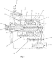
Fig. 1 is a cross-sectional view of an embodiment of a multispeed transmission in accordance with this disclosure; -
Fig. 2 is a cross-sectional view of another embodiment of a multispeed transmission in accordance with this disclosure; -
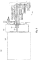
Fig. 3 is a schematic view of an embodiment of a system in accordance with this disclosure; and -
Fig. 4 is a chart of input speed vs. output speed in accordance with an embodiment of this disclosure. - Reference will now be made to the drawings wherein like reference numerals identify similar structural features or aspects of the subject disclosure. For purposes of explanation and illustration, and not limitation, an illustrative view of an embodiment of a transmission in accordance with the disclosure is shown in
Fig. 1 and is designated generally byreference character 100. Other embodiments and/or aspects of this disclosure are shown inFigs. 2-4 . The systems and methods described herein can be used to utilize the low speed spool for use in driving accessories (e.g., a generator). - A low speed
spool multispeed transmission 100 includes aninput shaft 101 configured to connect to a low pressure spool gearbox. Thetransmission 100 includes agear system 103 connected to theinput shaft 101 and configured to convert an input speed of theinput shaft 101 to an output speed within a predetermined speed range (e.g., about 7200 RPM to about 16000 RPM). - The
gear system 103 includes a plurality of gear states to change the ratio between the input speed and the output speed. Thegear system 103 also includes anoutput shaft 105 connected to thegear system 103 to be rotated by thegear system 103 at the output speed. Theoutput shaft 105 can be configured to connect to a generator (e.g., a variable frequency generator) or any other suitable accessory. As shown, theinput shaft 101 and theoutput shaft 105 can be coaxial. - In certain embodiments, the plurality of gear states can include three gear states (e.g., 1st gear, 2nd gear, and 3rd gear). Any other suitable number of speeds is contemplated herein.
- The
gear system 103 can include a firstplanetary gear 107 including afirst carrier 109 operatively connected to a plurality offirst planet gears 111, afirst ring gear 113 meshed with thefirst planet gears 111, and afirst sun gear 115 meshed with thefirst planet gears 111. In certain embodiments, thefirst sun gear 115 can be connected to theoutput shaft 105 such that theoutput shaft 105 rotates at the same speed as thefirst sun gear 115. - The
gear system 103 can include a second bi-coupledplanetary gear 117 including asecond carrier 119 operatively connected to a plurality ofsecond planet gears 121, asecond ring gear 123 meshed with thesecond planet gears 121, and asecond sun gear 125 meshed with asecond planet gears 121. Thesecond carrier 119 can be connected to the first ring gear 113 (e.g., via a spline) to rotate at the same speed as thefirst ring gear 113. - The
second ring gear 123 can be connected to the first carrier 109 (e.g., via a spline) to rotate at the same speed as thefirst carrier 109. Thegear system 103 can include afirst band brake 127 configured to brake thefirst ring gear 113. Thegear system 103 can include asecond band brake 129 configured to brake thesecond sun gear 125. Any other suitable type of braking mechanism is contemplated herein. - In certain embodiments, the
transmission 100 can include arelease device 135 for bypassing the gear system 103 (e.g., in the event of failure). The release device can be a pilot actuated solenoid, for example, and can include apull ring 137 for resetting after actuation. - In certain embodiments, the
transmission 100 can include one or more accessory pumps 139 (e.g., for pumping oils and/or hydraulic fluids for thegear system 103, a gearbox, or any other suitable system). Any suitable amount ofpumps 139 are contemplated herein. - In certain embodiments, the
transmission 100 can include a controller. The controller can include any suitable hardware and/or software for operating any suitable components (e.g., the release device, band brakes, and/or clutches) of thegear system 103. - In certain embodiments, the
transmission 100 can include an oil separator/permanent magnet generator (PMG) 141, e.g., to separate air from oil and/or for powering the controller. In certain embodiments, thePMG 141 can be used as speed sensor and can be connected to the controller. Thepumps 139 and/or the separator/PMG 141 can be connected to thegear system 103 in any suitable manner to be driven by thegear system 103 at any suitable speed(s). - The
gear system 103 can include an overrunning clutch 131 configured to connect thefirst carrier 109 to thefirst ring gear 113 to cause thefirst ring gear 113 and thefirst sun gear 115 to rotate at the same speed as thefirst carrier 109. Accordingly, the overrunning clutch 131 can limits speed ratio to 1:1 if neither band brake is engaged. - Referring to
Fig. 2 , in certain embodiments, agear system 203 can include asecond overrunning clutch 233 configured to connect thesecond sun gear 125 to thesecond band brake 129. In certain embodiments, thesecond overrunning clutch 233 can be useful if timing of releasing thefirst band brake 127 and engagement of thesecond band brake 129 is inaccurate such that both band brakes can be engaged together in first gear and thefirst band brake 127 can be released in second gear with engagement of thesecond overrunning clutch 233. - Referring to
Fig. 3 , aturbomachine generator system 300 can include a low speedspool gear box 301, a low speed spool multispeed transmission (e.g.,transmission 100 or any other suitable embodiments as described above), and agenerator 303 connected to theoutput shaft 105 of themultispeed transmission 100. Thegenerator 303 can be a variable frequency generator (VFG) or any other suitable generator or accessory. In certain embodiments, (e.g., for a 6-pole VFG), the predetermined speed range can be about 7200 RPM to about 16000 RPM. Any other suitable generator and/or predetermined speed range is contemplated herein. - In accordance with at least one aspect of this disclosure, as shown in
Fig. 1 , a 1st gear can be achieved by engaging only thefirst band brake 127. A 2nd gear can be achieved by releasing thefirst band brake 127 while engaging thesecond band brake 129. A 3rd gear can be achieve by engaging only the first overrunning clutch. - Table 1 below shows an embodiment of gear ratios. Table 2 below shows an embodiment of gear train characteristics. Table 3 below shows an embodiment of actual gear speeds of each gear in the
gear system 103 in each gear state. Table 4 below shows an embodiment of start-up gear speeds of each gear in the gear system in each gear state.Table 1 Actual Gear Ratios 1st Gear 3.6000 2nd Gear 1.9941 3rd Gear 1.0000 Min Input Speed (rpm) = 2000.00 Max Input Speed (rpm) = 16000.00 input Speed Ratio = 8.000 

Table 3 Actual Gear Speeds Gear Carrier Speed (rpm) Sun / VFG Speed (-rpm) Ring Speed (rpm) Planet Speed (rpm) 2nd Ring Speed (rpm) 2nd Carrier Speed 2nd Sun Speed (rpm) 2nd Planet Speed (rpm) Shift Zone (rpm) 1st 2000.0 7200.0 0.0 -6500.0 2000.0 0.0 -3230.8 10500.0 4444.4 16000.0 0.0 -14444.4 4444.4 0.0 -7179.5 23333.3 833.8 2nd 3610.6 7200.0 2230.1 -4486.7 3610.6 2230.1 0.0 7247.8 8023.6 16000.0 4955.8 -9970.5 8023.6 4955.8 0.0 16106.2 823.6 3rd 7200.0 7200.0 7200.0 0.0 7200.0 7200.0 7200.0 0.0 16000.0 16000.0 16000.0 0.0 16000.0 16000.0 16000.0 0.0 
-
Fig. 4 shows achart 400 of input speeds versus output speed in the various gears. Thechart 400 also shows start up shifts and embodiments of shift ranges shown in phantom. - Embodiments include a three speed transmission design with coaxial input and output for driving a 6-pole Variable Frequency Generator (VFG). Embodiments can are compact and allow a generator to be driven across an 8:1 input speed range (e.g., which can be a typical high bypass turbofan low pressure spool operating speed range). Selective control of the gears allows for maintaining a suitable generator output frequency (e.g., 360-800 Hz) across a wide input speed range by outputting a narrow speed range for driving accessories, e.g., VFGs.
- The methods and systems of the present disclosure, as described above and shown in the drawings, provide for gear systems with superior properties. While the apparatus and methods of the subject disclosure have been shown and described with reference to embodiments, those skilled in the art will readily appreciate that changes and/or modifications may be made thereto without departing from the scope of the subject disclosure.
Claims (15)
- A low speed spool multispeed transmission (100), comprising:an input shaft (101) configured to connect to a low pressure spool gearbox;a gear system (103) connected to the input shaft (101) and configured to convert an input speed of the input shaft (101) to an output speed within a predetermined speed range, wherein the gear system (103) includes a plurality of gear states to change a ratio between the input speed and the output speed; andan output shaft (105) connected to the gear system (103) to be rotated by the gear system (103) at the output speed, the output shaft (105) configured to connect to a generator.
- The transmission of claim 1, wherein the output shaft extends in a same axial direction from the transmission as the input shaft, and preferably wherein the input shaft and the output shaft are coaxial.
- The transmission of claim 1, wherein the plurality of gear states include a 1st gear, a 2nd gear, and a 3rd gear.
- The transmission of claim 1, wherein the gear system includes a first planetary gear including a first carrier operatively connected to a plurality of first planet gears, a first ring gear meshed with the first planet gears, and a first sun gear meshed with the first planet gears.
- The transmission of claim 4, wherein the first sun gear is connected to the output shaft such that the output shaft rotates at the same speed as the first sun gear.
- The transmission of claim 5, wherein the gear system includes a second bi-coupled planetary gear including a second carrier operatively connected to a plurality of second planet gears, a second ring gear meshed with the second planet gears, and a second sun gear meshed with a second planet gears
- The transmission of claim 6, wherein the second carrier is connected to the first ring gear to rotate at the same speed as the first ring gear.
- The transmission of claim 7, wherein the second ring gear is connected to the first carrier to rotate at the same speed as the first carrier, and preferably wherein the gear system includes a first band brake configured to brake the first ring gear, and more preferably wherein the gear system includes a second band brake configured to brake the second sun gear, and more preferably wherein the gear system includes an overrunning clutch configured to connect the first carrier to the first ring gear to cause the first ring gear and the first sun gear to rotate at the same speed as the first carrier, and more preferably further comprising a second overrunning clutch configured to connect the second sun gear to the second band brake.
- The transmission of claim 1, wherein the transmission is configured to maintain the output speed range within a 2.22:1 ratio when the input speed range varies as much as 8:1.
- A turbomachine generator system, comprising:a low speed spool gear box;a low speed spool multispeed transmission as claimed in claim 1; anda generator connected to the output shaft of the multispeed transmission.
- The system of claim 10, wherein the generator is a variable frequency generator and the predetermined speed range is about 7200 RPM to about 16000 RPM.
- The system of claim 10, wherein the input shaft and the output shaft are coaxial.
- The system of claim 10, wherein the plurality of gear states include three gear states.
- The system of claim 10, wherein the gear system includes a first planetary gear including a first carrier operatively connected to a plurality of first planet gears, a first ring gear meshed with the first planet gears, and a first sun gear meshed with the first planet gears.
- The system of claim 10, wherein the first sun gear is connected to the output shaft such that the output shaft rotates at the same speed as the first sun gear.
Applications Claiming Priority (1)
| Application Number | Priority Date | Filing Date | Title |
|---|---|---|---|
| US15/411,069 US10495186B2 (en) | 2017-01-20 | 2017-01-20 | Low speed spool generator transmission |
Publications (2)
| Publication Number | Publication Date |
|---|---|
| EP3351825A1 true EP3351825A1 (en) | 2018-07-25 |
| EP3351825B1 EP3351825B1 (en) | 2021-03-31 |
Family
ID=61017829
Family Applications (1)
| Application Number | Title | Priority Date | Filing Date |
|---|---|---|---|
| EP18152620.3A Active EP3351825B1 (en) | 2017-01-20 | 2018-01-19 | Low speed spool generator transmission |
Country Status (2)
| Country | Link |
|---|---|
| US (1) | US10495186B2 (en) |
| EP (1) | EP3351825B1 (en) |
Families Citing this family (17)
| Publication number | Priority date | Publication date | Assignee | Title |
|---|---|---|---|---|
| USD905758S1 (en) * | 2017-11-24 | 2020-12-22 | Siemens Aktiengesellschaft | Electric motor starter |
| JP1616481S (en) * | 2017-12-11 | 2018-10-29 | ||
| JP1619986S (en) * | 2018-02-09 | 2018-12-10 | ||
| JP1622555S (en) * | 2018-02-27 | 2019-01-21 | Motor actuator | |
| WO2019190996A1 (en) | 2018-03-26 | 2019-10-03 | Milwaukee Electric Tool Corporation | High-power battery-powered portable power source |
| US11271415B2 (en) | 2018-05-18 | 2022-03-08 | Milwaukee Electric Tool Corporation | Portable power source |
| USD906240S1 (en) * | 2018-06-04 | 2020-12-29 | Semikron Elektronik Gmbh & Co. Kg | Powercore module |
| USD909299S1 (en) * | 2018-07-12 | 2021-02-02 | Advanced Thermal Control, Inc. | Exothermic extermination device |
| USD900742S1 (en) * | 2018-08-02 | 2020-11-03 | Aws Holdings Llc | Water generator unit |
| JP7220233B2 (en) * | 2018-11-19 | 2023-02-09 | 川崎重工業株式会社 | generator for aircraft |
| US11028905B2 (en) | 2019-03-14 | 2021-06-08 | Hamilton Sundstrand Corporation | Coupled planetary gearbox |
| US10954864B2 (en) | 2019-03-25 | 2021-03-23 | Hamilton Sunstrand Corporation | Transmission for low spool of gas turbine engine |
| US11226026B2 (en) | 2019-04-18 | 2022-01-18 | Hamilton Sundstrand Corporation | Multispeed transmission |
| US11834998B2 (en) | 2019-04-18 | 2023-12-05 | Hamilton Sundstrand Corporation | Transmission systems having clutch at output side |
| USD933010S1 (en) | 2019-05-29 | 2021-10-12 | Milwaukee Electric Tool Corporation | Portable power source |
| US11248523B2 (en) | 2019-11-06 | 2022-02-15 | Raytheon Technologies Corporation | Dual clutch transmission for accessory gearbox drive |
| US12084195B2 (en) | 2021-04-29 | 2024-09-10 | Hamilton Sundstrand Corporation | Dual drive, dual clutch drive system for an aircraft accessory |
Citations (2)
| Publication number | Priority date | Publication date | Assignee | Title |
|---|---|---|---|---|
| EP2644867A2 (en) * | 2012-03-30 | 2013-10-02 | Hamilton Sundstrand Corporation | Aircraft accessory drive multiple speed transmission |
| DE102014216984A1 (en) * | 2014-08-26 | 2016-03-03 | Zf Friedrichshafen Ag | transmission |
Family Cites Families (11)
| Publication number | Priority date | Publication date | Assignee | Title |
|---|---|---|---|---|
| US3463180A (en) * | 1966-11-15 | 1969-08-26 | Nissan Motor | Automatic shifting device of automatic speed change gear for automobiles |
| JPS5146222B2 (en) * | 1972-10-06 | 1976-12-08 | ||
| US4665770A (en) * | 1985-03-18 | 1987-05-19 | Ford Motor Company | Control system for a multiple ratio transmission having a lockup clutch torque converter |
| US7552582B2 (en) * | 2005-06-07 | 2009-06-30 | Honeywell International Inc. | More electric aircraft power transfer systems and methods |
| US8039983B2 (en) | 2008-12-02 | 2011-10-18 | The Boeing Company | Systems and methods for providing AC power from multiple turbine engine spools |
| US20120221157A1 (en) * | 2011-02-28 | 2012-08-30 | Hamilton Sundstrand Corporation | Low pressure spool emergency generator |
| US20130232941A1 (en) | 2012-03-07 | 2013-09-12 | Ge Aviation Systems Llc | Apparatus for extracting input power from the low pressure spool of a turbine engine |
| JP2014113999A (en) * | 2012-04-05 | 2014-06-26 | Fine Mec:Kk | Automotive running gear, and control method thereof |
| GB201219544D0 (en) | 2012-10-31 | 2012-12-12 | Rolls Royce Deutschland | Geared compressor for gas turbine engine |
| GB201219916D0 (en) | 2012-11-06 | 2012-12-19 | Rolls Royce Plc | An electrical generation arrangement for an aircraft |
| CN105452613B (en) | 2013-06-06 | 2019-04-30 | 通用电气航空系统有限责任公司 | Jet engine assembly and method of generating electricity |
-
2017
- 2017-01-20 US US15/411,069 patent/US10495186B2/en active Active
-
2018
- 2018-01-19 EP EP18152620.3A patent/EP3351825B1/en active Active
Patent Citations (2)
| Publication number | Priority date | Publication date | Assignee | Title |
|---|---|---|---|---|
| EP2644867A2 (en) * | 2012-03-30 | 2013-10-02 | Hamilton Sundstrand Corporation | Aircraft accessory drive multiple speed transmission |
| DE102014216984A1 (en) * | 2014-08-26 | 2016-03-03 | Zf Friedrichshafen Ag | transmission |
Also Published As
| Publication number | Publication date |
|---|---|
| US10495186B2 (en) | 2019-12-03 |
| EP3351825B1 (en) | 2021-03-31 |
| US20180209513A1 (en) | 2018-07-26 |
Similar Documents
| Publication | Publication Date | Title |
|---|---|---|
| EP3351825B1 (en) | Low speed spool generator transmission | |
| US11231090B2 (en) | Heavy duty transmission architecture | |
| EP0716947B1 (en) | Hybrid power transmission | |
| US9121476B2 (en) | Control of shifting transmission for constant and variable frequency systems | |
| US20200332862A1 (en) | Multispeed transmission | |
| EP3284971A1 (en) | Single shaft two-speed drive system | |
| DE102015215547A1 (en) | Method for operating an automatic transmission of a motor vehicle | |
| US11118514B2 (en) | Turbomachine dual spool transmission systems | |
| DE102012208989B4 (en) | Controlling a transmission upshift with skipping gears | |
| KR20120063339A (en) | Compound planetary gear for automated manual transmission | |
| EP3423735A1 (en) | Multi-gear transmission layout | |
| CN110873156A (en) | Transmission for an engine with two power inputs | |
| US10961917B2 (en) | Turbomachine dual spool transmission systems | |
| US11834998B2 (en) | Transmission systems having clutch at output side | |
| US11713720B2 (en) | Turbomachine dual spool transmission systems | |
| WO2018174881A1 (en) | An apparatus and method of operating the same for multi-mode hybrid variable speed transmissions with smooth and uninterrupted mode shifting | |
| US11255273B2 (en) | Turbomachine dual spool transmission systems | |
| US10399431B2 (en) | Hybrid drive and operating method for a hybrid drive | |
| EP0145724B1 (en) | Epicyclic gear transmissions | |
| US20250369396A1 (en) | Gear changing system for an accessory gearbox of an aircraft turbine engine and method of use | |
| CN110285199A (en) | Power split continuously variable transmission system | |
| EP2998176B1 (en) | Retarder for a motor vehicle drive train, and motor vehicle drive train | |
| JP2018173136A (en) | Multistage transmission | |
| US2553998A (en) | Power train connection for changespeed transmissions | |
| KR20190130686A (en) | A brake arrangement for an upshift process in a gearbox |
Legal Events
| Date | Code | Title | Description |
|---|---|---|---|
| PUAI | Public reference made under article 153(3) epc to a published international application that has entered the european phase |
Free format text: ORIGINAL CODE: 0009012 |
|
| STAA | Information on the status of an ep patent application or granted ep patent |
Free format text: STATUS: THE APPLICATION HAS BEEN PUBLISHED |
|
| AK | Designated contracting states |
Kind code of ref document: A1 Designated state(s): AL AT BE BG CH CY CZ DE DK EE ES FI FR GB GR HR HU IE IS IT LI LT LU LV MC MK MT NL NO PL PT RO RS SE SI SK SM TR |
|
| AX | Request for extension of the european patent |
Extension state: BA ME |
|
| STAA | Information on the status of an ep patent application or granted ep patent |
Free format text: STATUS: REQUEST FOR EXAMINATION WAS MADE |
|
| 17P | Request for examination filed |
Effective date: 20190123 |
|
| RBV | Designated contracting states (corrected) |
Designated state(s): AL AT BE BG CH CY CZ DE DK EE ES FI FR GB GR HR HU IE IS IT LI LT LU LV MC MK MT NL NO PL PT RO RS SE SI SK SM TR |
|
| GRAP | Despatch of communication of intention to grant a patent |
Free format text: ORIGINAL CODE: EPIDOSNIGR1 |
|
| STAA | Information on the status of an ep patent application or granted ep patent |
Free format text: STATUS: GRANT OF PATENT IS INTENDED |
|
| RIC1 | Information provided on ipc code assigned before grant |
Ipc: F01D 15/00 20060101ALI20200423BHEP Ipc: F02C 7/36 20060101ALI20200423BHEP Ipc: F16H 3/66 20060101AFI20200423BHEP |
|
| INTG | Intention to grant announced |
Effective date: 20200512 |
|
| GRAJ | Information related to disapproval of communication of intention to grant by the applicant or resumption of examination proceedings by the epo deleted |
Free format text: ORIGINAL CODE: EPIDOSDIGR1 |
|
| STAA | Information on the status of an ep patent application or granted ep patent |
Free format text: STATUS: REQUEST FOR EXAMINATION WAS MADE |
|
| INTC | Intention to grant announced (deleted) | ||
| GRAP | Despatch of communication of intention to grant a patent |
Free format text: ORIGINAL CODE: EPIDOSNIGR1 |
|
| STAA | Information on the status of an ep patent application or granted ep patent |
Free format text: STATUS: GRANT OF PATENT IS INTENDED |
|
| INTG | Intention to grant announced |
Effective date: 20201029 |
|
| RIN1 | Information on inventor provided before grant (corrected) |
Inventor name: LEMMERS, GLENN C. JR. |
|
| GRAS | Grant fee paid |
Free format text: ORIGINAL CODE: EPIDOSNIGR3 |
|
| GRAA | (expected) grant |
Free format text: ORIGINAL CODE: 0009210 |
|
| STAA | Information on the status of an ep patent application or granted ep patent |
Free format text: STATUS: THE PATENT HAS BEEN GRANTED |
|
| AK | Designated contracting states |
Kind code of ref document: B1 Designated state(s): AL AT BE BG CH CY CZ DE DK EE ES FI FR GB GR HR HU IE IS IT LI LT LU LV MC MK MT NL NO PL PT RO RS SE SI SK SM TR |
|
| REG | Reference to a national code |
Ref country code: GB Ref legal event code: FG4D Ref country code: CH Ref legal event code: EP |
|
| REG | Reference to a national code |
Ref country code: AT Ref legal event code: REF Ref document number: 1377280 Country of ref document: AT Kind code of ref document: T Effective date: 20210415 |
|
| REG | Reference to a national code |
Ref country code: DE Ref legal event code: R096 Ref document number: 602018014540 Country of ref document: DE |
|
| REG | Reference to a national code |
Ref country code: IE Ref legal event code: FG4D |
|
| REG | Reference to a national code |
Ref country code: LT Ref legal event code: MG9D |
|
| PG25 | Lapsed in a contracting state [announced via postgrant information from national office to epo] |
Ref country code: NO Free format text: LAPSE BECAUSE OF FAILURE TO SUBMIT A TRANSLATION OF THE DESCRIPTION OR TO PAY THE FEE WITHIN THE PRESCRIBED TIME-LIMIT Effective date: 20210630 Ref country code: FI Free format text: LAPSE BECAUSE OF FAILURE TO SUBMIT A TRANSLATION OF THE DESCRIPTION OR TO PAY THE FEE WITHIN THE PRESCRIBED TIME-LIMIT Effective date: 20210331 Ref country code: HR Free format text: LAPSE BECAUSE OF FAILURE TO SUBMIT A TRANSLATION OF THE DESCRIPTION OR TO PAY THE FEE WITHIN THE PRESCRIBED TIME-LIMIT Effective date: 20210331 Ref country code: BG Free format text: LAPSE BECAUSE OF FAILURE TO SUBMIT A TRANSLATION OF THE DESCRIPTION OR TO PAY THE FEE WITHIN THE PRESCRIBED TIME-LIMIT Effective date: 20210630 |
|
| PG25 | Lapsed in a contracting state [announced via postgrant information from national office to epo] |
Ref country code: SE Free format text: LAPSE BECAUSE OF FAILURE TO SUBMIT A TRANSLATION OF THE DESCRIPTION OR TO PAY THE FEE WITHIN THE PRESCRIBED TIME-LIMIT Effective date: 20210331 Ref country code: RS Free format text: LAPSE BECAUSE OF FAILURE TO SUBMIT A TRANSLATION OF THE DESCRIPTION OR TO PAY THE FEE WITHIN THE PRESCRIBED TIME-LIMIT Effective date: 20210331 Ref country code: LV Free format text: LAPSE BECAUSE OF FAILURE TO SUBMIT A TRANSLATION OF THE DESCRIPTION OR TO PAY THE FEE WITHIN THE PRESCRIBED TIME-LIMIT Effective date: 20210331 |
|
| REG | Reference to a national code |
Ref country code: NL Ref legal event code: MP Effective date: 20210331 |
|
| REG | Reference to a national code |
Ref country code: AT Ref legal event code: MK05 Ref document number: 1377280 Country of ref document: AT Kind code of ref document: T Effective date: 20210331 |
|
| PG25 | Lapsed in a contracting state [announced via postgrant information from national office to epo] |
Ref country code: SM Free format text: LAPSE BECAUSE OF FAILURE TO SUBMIT A TRANSLATION OF THE DESCRIPTION OR TO PAY THE FEE WITHIN THE PRESCRIBED TIME-LIMIT Effective date: 20210331 Ref country code: NL Free format text: LAPSE BECAUSE OF FAILURE TO SUBMIT A TRANSLATION OF THE DESCRIPTION OR TO PAY THE FEE WITHIN THE PRESCRIBED TIME-LIMIT Effective date: 20210331 Ref country code: AT Free format text: LAPSE BECAUSE OF FAILURE TO SUBMIT A TRANSLATION OF THE DESCRIPTION OR TO PAY THE FEE WITHIN THE PRESCRIBED TIME-LIMIT Effective date: 20210331 Ref country code: CZ Free format text: LAPSE BECAUSE OF FAILURE TO SUBMIT A TRANSLATION OF THE DESCRIPTION OR TO PAY THE FEE WITHIN THE PRESCRIBED TIME-LIMIT Effective date: 20210331 Ref country code: EE Free format text: LAPSE BECAUSE OF FAILURE TO SUBMIT A TRANSLATION OF THE DESCRIPTION OR TO PAY THE FEE WITHIN THE PRESCRIBED TIME-LIMIT Effective date: 20210331 Ref country code: LT Free format text: LAPSE BECAUSE OF FAILURE TO SUBMIT A TRANSLATION OF THE DESCRIPTION OR TO PAY THE FEE WITHIN THE PRESCRIBED TIME-LIMIT Effective date: 20210331 |
|
| PG25 | Lapsed in a contracting state [announced via postgrant information from national office to epo] |
Ref country code: PL Free format text: LAPSE BECAUSE OF FAILURE TO SUBMIT A TRANSLATION OF THE DESCRIPTION OR TO PAY THE FEE WITHIN THE PRESCRIBED TIME-LIMIT Effective date: 20210331 Ref country code: PT Free format text: LAPSE BECAUSE OF FAILURE TO SUBMIT A TRANSLATION OF THE DESCRIPTION OR TO PAY THE FEE WITHIN THE PRESCRIBED TIME-LIMIT Effective date: 20210802 Ref country code: RO Free format text: LAPSE BECAUSE OF FAILURE TO SUBMIT A TRANSLATION OF THE DESCRIPTION OR TO PAY THE FEE WITHIN THE PRESCRIBED TIME-LIMIT Effective date: 20210331 Ref country code: SK Free format text: LAPSE BECAUSE OF FAILURE TO SUBMIT A TRANSLATION OF THE DESCRIPTION OR TO PAY THE FEE WITHIN THE PRESCRIBED TIME-LIMIT Effective date: 20210331 Ref country code: IS Free format text: LAPSE BECAUSE OF FAILURE TO SUBMIT A TRANSLATION OF THE DESCRIPTION OR TO PAY THE FEE WITHIN THE PRESCRIBED TIME-LIMIT Effective date: 20210731 |
|
| REG | Reference to a national code |
Ref country code: DE Ref legal event code: R097 Ref document number: 602018014540 Country of ref document: DE |
|
| PG25 | Lapsed in a contracting state [announced via postgrant information from national office to epo] |
Ref country code: AL Free format text: LAPSE BECAUSE OF FAILURE TO SUBMIT A TRANSLATION OF THE DESCRIPTION OR TO PAY THE FEE WITHIN THE PRESCRIBED TIME-LIMIT Effective date: 20210331 Ref country code: DK Free format text: LAPSE BECAUSE OF FAILURE TO SUBMIT A TRANSLATION OF THE DESCRIPTION OR TO PAY THE FEE WITHIN THE PRESCRIBED TIME-LIMIT Effective date: 20210331 Ref country code: ES Free format text: LAPSE BECAUSE OF FAILURE TO SUBMIT A TRANSLATION OF THE DESCRIPTION OR TO PAY THE FEE WITHIN THE PRESCRIBED TIME-LIMIT Effective date: 20210331 |
|
| PLBE | No opposition filed within time limit |
Free format text: ORIGINAL CODE: 0009261 |
|
| STAA | Information on the status of an ep patent application or granted ep patent |
Free format text: STATUS: NO OPPOSITION FILED WITHIN TIME LIMIT |
|
| 26N | No opposition filed |
Effective date: 20220104 |
|
| PG25 | Lapsed in a contracting state [announced via postgrant information from national office to epo] |
Ref country code: IS Free format text: LAPSE BECAUSE OF FAILURE TO SUBMIT A TRANSLATION OF THE DESCRIPTION OR TO PAY THE FEE WITHIN THE PRESCRIBED TIME-LIMIT Effective date: 20210731 |
|
| PG25 | Lapsed in a contracting state [announced via postgrant information from national office to epo] |
Ref country code: IT Free format text: LAPSE BECAUSE OF FAILURE TO SUBMIT A TRANSLATION OF THE DESCRIPTION OR TO PAY THE FEE WITHIN THE PRESCRIBED TIME-LIMIT Effective date: 20210331 |
|
| PG25 | Lapsed in a contracting state [announced via postgrant information from national office to epo] |
Ref country code: MC Free format text: LAPSE BECAUSE OF FAILURE TO SUBMIT A TRANSLATION OF THE DESCRIPTION OR TO PAY THE FEE WITHIN THE PRESCRIBED TIME-LIMIT Effective date: 20210331 |
|
| REG | Reference to a national code |
Ref country code: CH Ref legal event code: PL |
|
| REG | Reference to a national code |
Ref country code: BE Ref legal event code: MM Effective date: 20220131 |
|
| PG25 | Lapsed in a contracting state [announced via postgrant information from national office to epo] |
Ref country code: LU Free format text: LAPSE BECAUSE OF NON-PAYMENT OF DUE FEES Effective date: 20220119 |
|
| PG25 | Lapsed in a contracting state [announced via postgrant information from national office to epo] |
Ref country code: BE Free format text: LAPSE BECAUSE OF NON-PAYMENT OF DUE FEES Effective date: 20220131 |
|
| PG25 | Lapsed in a contracting state [announced via postgrant information from national office to epo] |
Ref country code: LI Free format text: LAPSE BECAUSE OF NON-PAYMENT OF DUE FEES Effective date: 20220131 Ref country code: CH Free format text: LAPSE BECAUSE OF NON-PAYMENT OF DUE FEES Effective date: 20220131 |
|
| PG25 | Lapsed in a contracting state [announced via postgrant information from national office to epo] |
Ref country code: IE Free format text: LAPSE BECAUSE OF NON-PAYMENT OF DUE FEES Effective date: 20220119 |
|
| P01 | Opt-out of the competence of the unified patent court (upc) registered |
Effective date: 20230522 |
|
| PG25 | Lapsed in a contracting state [announced via postgrant information from national office to epo] |
Ref country code: HU Free format text: LAPSE BECAUSE OF FAILURE TO SUBMIT A TRANSLATION OF THE DESCRIPTION OR TO PAY THE FEE WITHIN THE PRESCRIBED TIME-LIMIT; INVALID AB INITIO Effective date: 20180119 |
|
| PG25 | Lapsed in a contracting state [announced via postgrant information from national office to epo] |
Ref country code: MK Free format text: LAPSE BECAUSE OF FAILURE TO SUBMIT A TRANSLATION OF THE DESCRIPTION OR TO PAY THE FEE WITHIN THE PRESCRIBED TIME-LIMIT Effective date: 20210331 Ref country code: CY Free format text: LAPSE BECAUSE OF FAILURE TO SUBMIT A TRANSLATION OF THE DESCRIPTION OR TO PAY THE FEE WITHIN THE PRESCRIBED TIME-LIMIT Effective date: 20210331 |
|
| PG25 | Lapsed in a contracting state [announced via postgrant information from national office to epo] |
Ref country code: MT Free format text: LAPSE BECAUSE OF FAILURE TO SUBMIT A TRANSLATION OF THE DESCRIPTION OR TO PAY THE FEE WITHIN THE PRESCRIBED TIME-LIMIT Effective date: 20210331 |
|
| PG25 | Lapsed in a contracting state [announced via postgrant information from national office to epo] |
Ref country code: GR Free format text: LAPSE BECAUSE OF NON-PAYMENT OF DUE FEES Effective date: 20210331 |
|
| PG25 | Lapsed in a contracting state [announced via postgrant information from national office to epo] |
Ref country code: GR Free format text: LAPSE BECAUSE OF NON-PAYMENT OF DUE FEES Effective date: 20210331 |
|
| PG25 | Lapsed in a contracting state [announced via postgrant information from national office to epo] |
Ref country code: TR Free format text: LAPSE BECAUSE OF FAILURE TO SUBMIT A TRANSLATION OF THE DESCRIPTION OR TO PAY THE FEE WITHIN THE PRESCRIBED TIME-LIMIT Effective date: 20210331 |
|
| PGFP | Annual fee paid to national office [announced via postgrant information from national office to epo] |
Ref country code: GB Payment date: 20251219 Year of fee payment: 9 |
|
| PGFP | Annual fee paid to national office [announced via postgrant information from national office to epo] |
Ref country code: FR Payment date: 20251217 Year of fee payment: 9 |
|
| PGFP | Annual fee paid to national office [announced via postgrant information from national office to epo] |
Ref country code: DE Payment date: 20251217 Year of fee payment: 9 |