EP3351814A1 - Linear motion guide device and end cap for linear motion guide device - Google Patents
Linear motion guide device and end cap for linear motion guide device Download PDFInfo
- Publication number
- EP3351814A1 EP3351814A1 EP16846618.3A EP16846618A EP3351814A1 EP 3351814 A1 EP3351814 A1 EP 3351814A1 EP 16846618 A EP16846618 A EP 16846618A EP 3351814 A1 EP3351814 A1 EP 3351814A1
- Authority
- EP
- European Patent Office
- Prior art keywords
- raceway
- ball
- component
- slider
- guide rail
- Prior art date
- Legal status (The legal status is an assumption and is not a legal conclusion. Google has not performed a legal analysis and makes no representation as to the accuracy of the status listed.)
- Granted
Links
- 230000002093 peripheral effect Effects 0.000 claims abstract description 13
- 238000005096 rolling process Methods 0.000 claims description 12
- 230000037361 pathway Effects 0.000 claims description 5
- 239000000463 material Substances 0.000 claims description 4
- 239000007769 metal material Substances 0.000 claims description 3
- 229920003002 synthetic resin Polymers 0.000 claims description 3
- 239000000057 synthetic resin Substances 0.000 claims description 3
- 235000019994 cava Nutrition 0.000 abstract description 2
- 238000003780 insertion Methods 0.000 description 8
- 230000037431 insertion Effects 0.000 description 8
- 230000000694 effects Effects 0.000 description 5
- 230000035939 shock Effects 0.000 description 3
- 229930040373 Paraformaldehyde Natural products 0.000 description 2
- 238000004519 manufacturing process Methods 0.000 description 2
- 238000000034 method Methods 0.000 description 2
- 229920006324 polyoxymethylene Polymers 0.000 description 2
- 210000005182 tip of the tongue Anatomy 0.000 description 2
- 229910001315 Tool steel Inorganic materials 0.000 description 1
- 229910045601 alloy Inorganic materials 0.000 description 1
- 239000000956 alloy Substances 0.000 description 1
- 230000005489 elastic deformation Effects 0.000 description 1
- 230000002708 enhancing effect Effects 0.000 description 1
- -1 polyoxymethylene Polymers 0.000 description 1
- 238000009877 rendering Methods 0.000 description 1
Images




Classifications
-
- F—MECHANICAL ENGINEERING; LIGHTING; HEATING; WEAPONS; BLASTING
- F16—ENGINEERING ELEMENTS AND UNITS; GENERAL MEASURES FOR PRODUCING AND MAINTAINING EFFECTIVE FUNCTIONING OF MACHINES OR INSTALLATIONS; THERMAL INSULATION IN GENERAL
- F16C—SHAFTS; FLEXIBLE SHAFTS; ELEMENTS OR CRANKSHAFT MECHANISMS; ROTARY BODIES OTHER THAN GEARING ELEMENTS; BEARINGS
- F16C29/00—Bearings for parts moving only linearly
- F16C29/04—Ball or roller bearings
- F16C29/06—Ball or roller bearings in which the rolling bodies circulate partly without carrying load
- F16C29/0602—Details of the bearing body or carriage or parts thereof, e.g. methods for manufacturing or assembly
- F16C29/0609—Details of the bearing body or carriage or parts thereof, e.g. methods for manufacturing or assembly of the ends of the bearing body or carriage where the rolling elements change direction, e.g. end caps
-
- F—MECHANICAL ENGINEERING; LIGHTING; HEATING; WEAPONS; BLASTING
- F16—ENGINEERING ELEMENTS AND UNITS; GENERAL MEASURES FOR PRODUCING AND MAINTAINING EFFECTIVE FUNCTIONING OF MACHINES OR INSTALLATIONS; THERMAL INSULATION IN GENERAL
- F16C—SHAFTS; FLEXIBLE SHAFTS; ELEMENTS OR CRANKSHAFT MECHANISMS; ROTARY BODIES OTHER THAN GEARING ELEMENTS; BEARINGS
- F16C29/00—Bearings for parts moving only linearly
- F16C29/04—Ball or roller bearings
- F16C29/06—Ball or roller bearings in which the rolling bodies circulate partly without carrying load
-
- F—MECHANICAL ENGINEERING; LIGHTING; HEATING; WEAPONS; BLASTING
- F16—ENGINEERING ELEMENTS AND UNITS; GENERAL MEASURES FOR PRODUCING AND MAINTAINING EFFECTIVE FUNCTIONING OF MACHINES OR INSTALLATIONS; THERMAL INSULATION IN GENERAL
- F16C—SHAFTS; FLEXIBLE SHAFTS; ELEMENTS OR CRANKSHAFT MECHANISMS; ROTARY BODIES OTHER THAN GEARING ELEMENTS; BEARINGS
- F16C29/00—Bearings for parts moving only linearly
- F16C29/04—Ball or roller bearings
- F16C29/06—Ball or roller bearings in which the rolling bodies circulate partly without carrying load
- F16C29/0633—Ball or roller bearings in which the rolling bodies circulate partly without carrying load with a bearing body defining a U-shaped carriage, i.e. surrounding a guide rail or track on three sides
- F16C29/0635—Ball or roller bearings in which the rolling bodies circulate partly without carrying load with a bearing body defining a U-shaped carriage, i.e. surrounding a guide rail or track on three sides whereby the return paths are provided as bores in a main body of the U-shaped carriage, e.g. the main body of the U-shaped carriage is a single part with end caps provided at each end
- F16C29/0638—Ball or roller bearings in which the rolling bodies circulate partly without carrying load with a bearing body defining a U-shaped carriage, i.e. surrounding a guide rail or track on three sides whereby the return paths are provided as bores in a main body of the U-shaped carriage, e.g. the main body of the U-shaped carriage is a single part with end caps provided at each end with balls
- F16C29/0642—Ball or roller bearings in which the rolling bodies circulate partly without carrying load with a bearing body defining a U-shaped carriage, i.e. surrounding a guide rail or track on three sides whereby the return paths are provided as bores in a main body of the U-shaped carriage, e.g. the main body of the U-shaped carriage is a single part with end caps provided at each end with balls with four rows of balls
-
- F—MECHANICAL ENGINEERING; LIGHTING; HEATING; WEAPONS; BLASTING
- F16—ENGINEERING ELEMENTS AND UNITS; GENERAL MEASURES FOR PRODUCING AND MAINTAINING EFFECTIVE FUNCTIONING OF MACHINES OR INSTALLATIONS; THERMAL INSULATION IN GENERAL
- F16C—SHAFTS; FLEXIBLE SHAFTS; ELEMENTS OR CRANKSHAFT MECHANISMS; ROTARY BODIES OTHER THAN GEARING ELEMENTS; BEARINGS
- F16C29/00—Bearings for parts moving only linearly
- F16C29/04—Ball or roller bearings
- F16C29/06—Ball or roller bearings in which the rolling bodies circulate partly without carrying load
- F16C29/0633—Ball or roller bearings in which the rolling bodies circulate partly without carrying load with a bearing body defining a U-shaped carriage, i.e. surrounding a guide rail or track on three sides
- F16C29/0635—Ball or roller bearings in which the rolling bodies circulate partly without carrying load with a bearing body defining a U-shaped carriage, i.e. surrounding a guide rail or track on three sides whereby the return paths are provided as bores in a main body of the U-shaped carriage, e.g. the main body of the U-shaped carriage is a single part with end caps provided at each end
- F16C29/0638—Ball or roller bearings in which the rolling bodies circulate partly without carrying load with a bearing body defining a U-shaped carriage, i.e. surrounding a guide rail or track on three sides whereby the return paths are provided as bores in a main body of the U-shaped carriage, e.g. the main body of the U-shaped carriage is a single part with end caps provided at each end with balls
- F16C29/0642—Ball or roller bearings in which the rolling bodies circulate partly without carrying load with a bearing body defining a U-shaped carriage, i.e. surrounding a guide rail or track on three sides whereby the return paths are provided as bores in a main body of the U-shaped carriage, e.g. the main body of the U-shaped carriage is a single part with end caps provided at each end with balls with four rows of balls
- F16C29/0647—Ball or roller bearings in which the rolling bodies circulate partly without carrying load with a bearing body defining a U-shaped carriage, i.e. surrounding a guide rail or track on three sides whereby the return paths are provided as bores in a main body of the U-shaped carriage, e.g. the main body of the U-shaped carriage is a single part with end caps provided at each end with balls with four rows of balls with load directions in X-arrangement
-
- F—MECHANICAL ENGINEERING; LIGHTING; HEATING; WEAPONS; BLASTING
- F16—ENGINEERING ELEMENTS AND UNITS; GENERAL MEASURES FOR PRODUCING AND MAINTAINING EFFECTIVE FUNCTIONING OF MACHINES OR INSTALLATIONS; THERMAL INSULATION IN GENERAL
- F16C—SHAFTS; FLEXIBLE SHAFTS; ELEMENTS OR CRANKSHAFT MECHANISMS; ROTARY BODIES OTHER THAN GEARING ELEMENTS; BEARINGS
- F16C29/00—Bearings for parts moving only linearly
- F16C29/04—Ball or roller bearings
- F16C29/06—Ball or roller bearings in which the rolling bodies circulate partly without carrying load
- F16C29/0633—Ball or roller bearings in which the rolling bodies circulate partly without carrying load with a bearing body defining a U-shaped carriage, i.e. surrounding a guide rail or track on three sides
- F16C29/0652—Ball or roller bearings in which the rolling bodies circulate partly without carrying load with a bearing body defining a U-shaped carriage, i.e. surrounding a guide rail or track on three sides whereby the return paths are at least partly defined by separate parts, e.g. covers attached to the legs of the main body of the U-shaped carriage
- F16C29/0654—Ball or roller bearings in which the rolling bodies circulate partly without carrying load with a bearing body defining a U-shaped carriage, i.e. surrounding a guide rail or track on three sides whereby the return paths are at least partly defined by separate parts, e.g. covers attached to the legs of the main body of the U-shaped carriage with balls
- F16C29/0659—Ball or roller bearings in which the rolling bodies circulate partly without carrying load with a bearing body defining a U-shaped carriage, i.e. surrounding a guide rail or track on three sides whereby the return paths are at least partly defined by separate parts, e.g. covers attached to the legs of the main body of the U-shaped carriage with balls with four rows of balls
- F16C29/0664—Ball or roller bearings in which the rolling bodies circulate partly without carrying load with a bearing body defining a U-shaped carriage, i.e. surrounding a guide rail or track on three sides whereby the return paths are at least partly defined by separate parts, e.g. covers attached to the legs of the main body of the U-shaped carriage with balls with four rows of balls with load directions in X-arrangement
-
- F—MECHANICAL ENGINEERING; LIGHTING; HEATING; WEAPONS; BLASTING
- F16—ENGINEERING ELEMENTS AND UNITS; GENERAL MEASURES FOR PRODUCING AND MAINTAINING EFFECTIVE FUNCTIONING OF MACHINES OR INSTALLATIONS; THERMAL INSULATION IN GENERAL
- F16C—SHAFTS; FLEXIBLE SHAFTS; ELEMENTS OR CRANKSHAFT MECHANISMS; ROTARY BODIES OTHER THAN GEARING ELEMENTS; BEARINGS
- F16C2226/00—Joining parts; Fastening; Assembling or mounting parts
- F16C2226/50—Positive connections
- F16C2226/60—Positive connections with threaded parts, e.g. bolt and nut connections
Definitions
- the present invention relates to a linear motion guiding device that includes a ball as a rolling element.
- the linear motion guiding device that includes the ball as the rolling element includes a guide rail, a slider, and a plurality of balls.
- the slider is provided at an outside of the guide rail.
- the guide rail and the slider face with each other and respectively have, at facing positions, raceway grooves that form raceways of the balls. Both of the raceway grooves extend in a longer direction of the guide rail.
- the slider includes a slider main body and a pair of end caps, the raceway groove and a return path of the ball are formed to the slider main body, and the direction changing passage of the ball is formed to the end cap.
- the ball is provided in the circulation pathway including the raceway, the return path, and the direction changing passage, and via the ball that rolls within the raceway in a load state, the slider linearly moves along the guide rail.
- a groove that forms the outer peripheral surface of the direction changing passage and includes an arc-shaped cross section (hereinafter, referred to as "arc groove").
- arc groove Formed on an end of a side of the raceway of the arc groove is a tongue unit that scoops up the ball from the raceway and guides the ball to the direction changing passage.
- PTL 1 proposes to make a tip, to which the ball clashes, of the tongue unit to be a planar tip that is perpendicular to the direction in which the raceway (rolling element rolling passages) extends, a convex tip, or concave tip having a curvature radius of the radius or more of the ball. Accordingly, compared to a case when the tip is sharp, the contact area after the elastic deformation associated with the clash of the ball becomes large (when tip is concave, surface contact may occur), and thus, PTL 1 discloses that the contact pressure becomes small and the plastic deformation(damage) is unlikely to occur to the tip.
- PTL 2 proposes that a portion of a front of at least the tongue unit of the arc groove is made to form Gothic arc shape, and by rendering the ball in a two-point contact state at the front of the tongue unit, the impact force applied to the ball is dispersed.
- PTL 2 further discloses that when a line connecting the contact point of the ball relative to the tongue unit (scooping unit) with the center of the ball contacted with the tongue unit is L10, and a line connecting the center of the ball contacted with the tongue unit and the groove bottom of the Gothic arc shaped arc groove is L20, an angle between L10 and L20 is preferably 40 degrees or more and 60 degrees or less.
- PTL 3 discloses that only the tongue unit (rolling element scoop-up unit that scoops up rolling element from load rolling path to direction changing passage) is separated from the end cap, the end cap includes a main body and the tongue unit attached thereto, and the tongue unit is formed by a material having higher shock resistance than that of the main body.
- the tongue unit is, via a fastening member such as thread, fixed to the main body.
- An object of the present invention is to provide a linear motion guiding device that is unlikely to cause a damage to a tongue unit of an end cap even when the linear motion guiding device is used under high-speed conditions.
- a fist aspect of the present invention provides the linear motion guiding device having following configurations of (1) to (4).
- the tongue unit satisfies the above configuration (4), and thus, two boundaries between the plane and the circular-arc surface are present, and the ball contacts the two boundaries when the ball is scooped up with the tongue unit. Accordingly, the impact force of the ball is dispersed into two places, and thus, the occurrence of the crack to the tongue unit is suppressed even when the tongue unit is used under the high-speed conditions.
- the tongue unit can smoothly scoop up the ball.
- the groove bottom line of the arc groove is Lm
- straight lines connecting the contact point of the ball relative to the distal end surface with a center Oe of an opening circle E of the raceway side of the direction changing passage present on the groove bottom line Lm are L1 and L2
- an angle between the groove bottom line Lm and the straight lines L1 and L2 is 20 degrees or more and 40 degrees or less.
- the configuration (5) does not limit components of the linear motion guiding device of the first aspect.
- the first component and the second component formed with the tongue unit are made of metal materials, and thus, compared to the end cap having the tongue unit made of synthetic resins, the damage is unlikely to occur to the tongue unit. Further, compared to a case where only the tongue unit is separated from the end cap, the tongue unit is made of materials having higher shock resistance than that of the main body, and the tongue unit is connected with the main body, an intensity of a tongue unit is increased.
- a linear motion guiding device 10 includes a guide rail 1, a slider 2, and a plurality of balls 3.
- the slider 2 has a shape in which leg units 2A provided at both sides of the width direction of the guide rail 1 and a body unit 2B for connecting both of the leg units 2A are integrated.
- the guide rail 1 is metallic, includes an upper surface 111 that faces an inner surface of the body unit 2B of the slider 2, and includes a side surface 112 that faces an inner surface of the leg units 2A. At an upper corner including the upper surface 111 and the side surface 112 of the guide rail 1, a raceway groove 11 is formed, and to the side surface 112 of the guide rail 1, a raceway groove 12 is formed.
- the slider 2 is, in a linear motion direction of the guide rail 1, divided into the slider main body 21, a pair of end caps 22, and a pair of side seals 23.
- the slider main body 21 is metallic and at an inside of the leg unit 21A, at positions facing with respective raceway grooves 11 and 12 of the guide rail 1, the raceway grooves 211 and 212 are respectively formed.
- a return path 216 corresponding to the respective raceway grooves 211 and 212 is formed.
- the raceway groove 12 of the guide rail 1 and the raceway grooves 211 and 212 of the slider 2 are Gothic arc grooves in which two arcs having different centers are combined.
- an offset design is conducted such that an interval between the upper raceway groove and the lower raceway groove in the guide rail 1 is different from an interval between the upper raceway groove and the lower raceway groove in the slider main body 21 (A>B) .
- the offset amount of the upper raceway is ⁇ 1 and the offset amount of the lower raceway is ⁇ 2.
- an end cap 22 includes a pair of leg units 22A and a body unit 22B, and on a surface of the slider main body side of each leg unit 22A, arc grooves 221 and 222 that form the outer peripheral surface of the direction changing passage and a concave unit 223 to which the return guide 24 is fitted are formed.
- a leg unit 22A at a left side of FIG. 3 illustrates the concave unit 223 before the return guide 24 is fitted, and the leg unit 22A of a right side of FIG. 3 illustrates the concave unit 223 after the return guide 24 is fitted.
- the two pairs of four rows raceway is formed, and each raceway is connected with each return path 216 via the direction changing passage.
- the circulation pathway of the balls 3 including the raceway, the return path 216, and the direction changing passage is provided in two pairs of four rows, and within each circulation pathway, the plurality of balls 3 are provided. Accordingly, in the linear motion guiding device 10, via the ball 3 rolling within the two pairs of four rows raceway in the load state, the slider 2 linearly moves along the guide rail 1.
- a tongue unit 25 that scoops up the ball 3 from the raceway and guides the ball to each direction changing passage is formed.
- FIG. 4 is a partial enlarged view obtained by enlarging the arc groove 222 and the tongue unit 25 of the end cap 22.
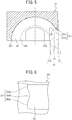
- FIG. 5 illustrates the cross-sectional view taken along a line A-A of FIG. 4 and
- FIG. 6 illustrates an arrow view as viewed from an arrow B of FIG. 4 .
- a distal end surface 251 of the tongue unit 25 includes a pair of planes 251a that is perpendicular to a direction L0 in which the raceway 41 configured of the raceway grooves 12 and 212 extends and a circular-arc surface 251b that caves into an arc-shape from a surface including both planes 251a.
- the ball 3 is scooped up by the tongue unit 25 from the raceway 41 and is guided to a direction changing passage 42 including the arc groove 222 of the end cap 22 and the internal arc surface 242 of the return guide 24.
- FIG. 7 is an arrow view as viewed from an arrow C of FIG. 4 and illustrates a pair of planes 251a and the circular-arc surface 251b with respect to either one of lines S1 or S2 indicating both ends in the width direction of the distal end surface 251.
- a center Os of a circle indicating the curvature of the circular-arc surface 251b is present on a straight line Ls that is shifted to upside from the groove bottom line Lm of the arc groove 222 by at least an offset amount ⁇ 2.
- a curvature radius R of the circular-arc surface 251b is smaller than the radius of the ball 3.
- FIG. 8 is a perspective view obtained by viewing the tongue unit 25 from the distal end surface 251 side.
- angles ⁇ 1 and ⁇ 2 between the groove bottom line Lm and the straight lines L1 and L2 are from 20 degrees or more to 40 degrees or less.
- the angles ⁇ 1 and ⁇ 2 can be altered by changing the curvature radius R ( FIG. 7 ) of the circular-arc surface 251b.
- angles ⁇ 1 and ⁇ 2 relative to the groove bottom line Lm of the contact points T1 and T2 of the ball 3 that contacts with the tip of the tongue unit 25 at two points are in the range from 20 degrees or more to 40 degrees or less, compared to a case where the angels are not within this range, the tongue unit 25 can smoothly scoop up the ball 3.
- a linear motion guiding device includes an end cap 5 illustrated in FIG. 9 instead of the end cap 22 configuring the slider 2 in the linear motion guiding device of FIG. 1 .
- the end cap 5 includes a first component 51, a second component 52, a third component 53, and two bolts (fastener component)54.
- the first component 51 includes a first leg unit 501 provided at one side in the width direction of the guide rail, and to the surface of the slider main body side, arc grooves 511 and 512 that form the outer peripheral surface of the direction changing passage of the ball are formed.
- the arc grooves 511 and 512 have, at the end of the raceway side, the tongue units 511a and 512a.
- a concave unit 512b to which the end of a holding wire for holding the ball is fitted is formed.
- a concave unit 515 to which the return guide 6 is fitted is formed.
- the second component 52 includes a second leg unit 502 that is provided to the other side in the width direction of the guide rail, and to the surface of the slider main body side, arc grooves 521 and 522 that form the outer peripheral surface of the direction changing passage of the ball are formed.
- the arc grooves 521 and 522 have, at the end of the raceway side, the tongue units 521a and 522a.
- a concave unit 522b to which the end of the holding wire for holding the ball is fitted is formed.
- a concave unit 525 to which the return guide 6 is fitted is formed.
- the third component 53 includes a part 503 provided above the guide rail, engagement surfaces 531 and 532 with the first component 51, and engagement surfaces 533 and 534 with the second component 52.
- the first component 51 includes engagement surfaces 513 and 514 that contact with respective engagement surfaces 531 and 532 of the third component 53.
- a female thread 513a to which a tip of a bolt 54 is screwed is formed.
- the second component 52 includes engagement surfaces 523 and 524 that contact with the respective engagement surfaces 533 and 534 of the third component 53.
- a female thread 523a to which a tip of the bolt 54 is screwed is formed.
- the third component 53 includes bolt insertion holes 535 and 536 through which a bolt vertically passes through.
- the bolt insertion hole 535 communicates with the female thread 513a of the first component 51 under a state where the engagement surface 531 contacts with the engagement surface 513 of the first component 51 and the engagement surface 532 contacts with the engagement surface 514 of the first component 51.
- a bolt insertion hole 536 communicates with the female thread 523a under a state where the engagement surface 533 contacts with the engagement surface 523 of the second component 52 and the engagement surface 534 contacts with an engagement surface 524 of the second component 52.
- the first component 51 and the second component 52 are made of an alloy tool steel, and the third component 53 is made of polyoxymethylene (POM).
- the end cap 5 is assembled by the following method.
- the engagement surface 531 of the third component 53 is caused to contact with the engagement surface 513 of the first component 51
- the engagement surface 532 of the third component 53 is caused to contact with the engagement surface 514 of the first component 51
- the bolt insertion hole 535 is caused to communicate with the female thread 513a
- the bolt 54 is inserted into the bolt insertion hole 535
- a male thread of the bolt 54 is screwed with the female thread 513a.
- the engagement surface 533 of the third component 53 is caused to contact with the engagement surface 523 of the second component 52
- the engagement surface 534 of the third component 53 is caused to contact with the engagement surface 524 of the second component 52
- the bolt insertion hole 536 is caused to communicate with the female thread 523a
- the bolt 54 is inserted into the bolt insertion hole 536
- a male thread of the bolt 54 is screwed with the female thread 523a.
- first component 51 and the second component 52, and the third component 53 are connected via the bolt 54 to form the end cap 5.
- the arc grooves 511 and 512 having the tongue units 511a and 512a are formed to the first component 51 and the arc grooves 521 and 522 having the tongue units 521a and 522a are formed to the second component 52, and since the first component 51 and the second component 52 are metallic, compared to a component the entirety of which is integrally made of synthetic resins, the tongue units 11a, 512a, 521a, and 522a have an excellent durability against the impact force of the ball 3.
- the material cost and the manufacturing cost can be reduced.
- the third component 53 is should be a common component and the first component 51 and the second component 52 having different specifications should be prepared, and accordingly it is possible to handle an end cap of a plurality of specifications.
- All of the first component 51, the second component 52, and the third component 53 can be metallic and connected via the bolt 54 to produce an end cap.
Landscapes
- Engineering & Computer Science (AREA)
- General Engineering & Computer Science (AREA)
- Mechanical Engineering (AREA)
- Bearings For Parts Moving Linearly (AREA)
Abstract
Description
- The present invention relates to a linear motion guiding device that includes a ball as a rolling element.
- The linear motion guiding device that includes the ball as the rolling element includes a guide rail, a slider, and a plurality of balls. The slider is provided at an outside of the guide rail. The guide rail and the slider face with each other and respectively have, at facing positions, raceway grooves that form raceways of the balls. Both of the raceway grooves extend in a longer direction of the guide rail.
- The slider includes a slider main body and a pair of end caps, the raceway groove and a return path of the ball are formed to the slider main body, and the direction changing passage of the ball is formed to the end cap. The ball is provided in the circulation pathway including the raceway, the return path, and the direction changing passage, and via the ball that rolls within the raceway in a load state, the slider linearly moves along the guide rail.
- Formed on a surface of a side of the slider main body of the end cap, is a groove that forms the outer peripheral surface of the direction changing passage and includes an arc-shaped cross section (hereinafter, referred to as "arc groove"). Formed on an end of a side of the raceway of the arc groove is a tongue unit that scoops up the ball from the raceway and guides the ball to the direction changing passage.
- When the linear motion guiding device is driven at a high speed, since the ball repeatedly clashes with the tongue unit of the end cap at high speed, a damage easily occurs to the tongue unit. Therefore, conventionally, a method for enhancing the stiffness of the tongue unit has been proposed.
- For example,
PTL 1 proposes to make a tip, to which the ball clashes, of the tongue unit to be a planar tip that is perpendicular to the direction in which the raceway (rolling element rolling passages) extends, a convex tip, or concave tip having a curvature radius of the radius or more of the ball. Accordingly, compared to a case when the tip is sharp, the contact area after the elastic deformation associated with the clash of the ball becomes large (when tip is concave, surface contact may occur), and thus,PTL 1 discloses that the contact pressure becomes small and the plastic deformation(damage) is unlikely to occur to the tip. - PTL 2 proposes that a portion of a front of at least the tongue unit of the arc groove is made to form Gothic arc shape, and by rendering the ball in a two-point contact state at the front of the tongue unit, the impact force applied to the ball is dispersed.
-
PTL 2 further discloses that when a line connecting the contact point of the ball relative to the tongue unit (scooping unit) with the center of the ball contacted with the tongue unit is L10, and a line connecting the center of the ball contacted with the tongue unit and the groove bottom of the Gothic arc shaped arc groove is L20, an angle between L10 and L20 is preferably 40 degrees or more and 60 degrees or less. -
PTL 3 discloses that only the tongue unit (rolling element scoop-up unit that scoops up rolling element from load rolling path to direction changing passage) is separated from the end cap, the end cap includes a main body and the tongue unit attached thereto, and the tongue unit is formed by a material having higher shock resistance than that of the main body. The tongue unit is, via a fastening member such as thread, fixed to the main body. -
- PTL 1:
JP 2004-68880 - PTL 2:
JP 4606416 - PTL 3:
JP 2008-275065 - With respect to the end cap disclosed in
PTL 1, when the ball is scooped up with the tongue unit, the ball contacts at one point to the tongue unit, and thus, in terms of the shock resistance of the tongue unit when the tongue unit is used under high-speed conditions, there is room for improvement. - With respect to the end cap disclosed in
PTL 2, at least a portion of the arc groove is formed into the Gothic arc shape, and thus, in terms of the manufacturing cost, there is room for improvement. - With respect to the end cap disclosed in
PTL 3, when a fixed part is used under the high-speed conditions, a stiffness of the fixed part is insufficient, and thus, in terms of the durability, there is room for improvement. - An object of the present invention is to provide a linear motion guiding device that is unlikely to cause a damage to a tongue unit of an end cap even when the linear motion guiding device is used under high-speed conditions.
- To achieve the above object, a fist aspect of the present invention provides the linear motion guiding device having following configurations of (1) to (4).
- (1) The linear motion guiding device includes the guide rail, the slider, and a plurality of balls, and the slider is provided to an outside of the guide rail. The guide rail and the slider face with each other, and at facing positions, respectively have raceway grooves that form raceways of the balls. Both of the raceway grooves extend in a longer direction of the guide rail.
- (2) The slider includes a slider main body and a pair of end caps, the raceway groove and the return path of the ball are formed on the slider main body, and the direction changing passage of the ball is formed on the end cap. The ball is provided in a circulation pathway including the raceway, the return path, and the direction changing passage, and via the ball rolling within the raceway in the load state, the slider linearly moves along the guide rail.
- (3) On a surface of a side of the slider main body of the end cap, an arc groove that forms an outer peripheral surface of the direction changing passage is formed. To an end of a side of the raceway of the arc groove, a tongue unit that scoops up the ball from the raceway and guides the ball to the direction changing passage is formed.
- (4) Distal end surfaces of the tongue unit include a plane that is perpendicular to the direction along the raceway and a circular-arc surface that recesses in an arc shape from the plane. A curvature radius of the circular-arc surface is smaller than a radius of the ball. A center of a circle indicating a curvature of the circular-arc surface is present on a line that is shifted from a groove bottom line of the arc groove by at least an offset amount between the raceway groove of the guide rail side and the raceway groove of the slider side.
To achieve the above object, a second aspect of the present invention provides the end cap of the linear motion guiding device having following configurations of (11) to (14) . - (11) The linear motion guiding device includes the guide rail, the slider, and the ball, via the ball rolling in the load state within the raceway formed with the raceway groove that is provided to facing positions of the guide rail and the slider, the slider linearly moves along the guide rail in the linear motion guiding device, and the end cap configures the slider of the linear motion guiding device.
- (12) The end cap includes a first component, a second component, and a third component. The first component includes a first leg unit that is provided at one side of the guide rail in a width direction, the arc groove that forms the outer peripheral surface of the direction changing passage of the ball is formed, and to the end of the raceway side on the arc groove, the tongue unit that scoops up the ball from the raceway and guides the ball to the direction changing passage is formed. The second component includes a second leg unit that is provided to the other side of the guide rail in the width direction, the arc groove that forms the outer peripheral surface of the direction changing passage of the ball is formed, and to the end of the raceway side of the arc groove, the tongue unit that scoops up the ball from the raceway and guides the ball to the direction changing passage is formed. The third component includes a part provided above the guide rail and includes an engagement surface with the first component and the second component.
- (13) The first component and the second component are made of metal materials.
- (14) The first component and the second component, and the third component are connected via a fastener component.
- According to the present invention, it is possible to provide a linear motion guiding device that is unlikely to cause a damage to a tongue unit of an end cap even when the linear motion guiding device is used under high-speed conditions.
-
-
FIG. 1 is a partially cutaway perspective view illustrating a linear motion guiding device according to a first embodiment; -
FIG. 2 is a partial front view explaining a raceway of the linear motion guiding device according to the first embodiment; -
FIG. 3 is a front view illustrating a slider main body side of an end cap configuring the linear motion guiding device according to the first embodiment; -
FIG. 4 is a partial enlarged view ofFIG. 3 ; -
FIG. 5 cross-sectional view taken along a line A-A ofFIG. 4 ; -
FIG. 6 is a view as viewed from the arrow B inFIG. 4 ; -
FIG. 7 is a drawing for explaining a relationship between the distal end surface of the tongue unit and the arc groove in the end cap ofFIG. 3 ; -
FIG. 8 is an enlarged perspective view of the distal end surface of the tongue unit; -
FIG. 9 is a front view illustrating a slider main body side of an end cap configuring a linear motion guiding device according to a second embodiment; and -
FIG. 10 is a front view illustrating each component configuring the end cap ofFIG. 9 . - The tongue unit satisfies the above configuration (4), and thus, two boundaries between the plane and the circular-arc surface are present, and the ball contacts the two boundaries when the ball is scooped up with the tongue unit. Accordingly, the impact force of the ball is dispersed into two places, and thus, the occurrence of the crack to the tongue unit is suppressed even when the tongue unit is used under the high-speed conditions.
- Note that descriptions of the effect do not limit components of the present invention and the linear motion guiding device of the first aspect.
- When the linear motion guiding device of the one aspect has the below configuration (5), compared to a case where the linear motion guiding device does not have the below configuration (5), the tongue unit can smoothly scoop up the ball.
(5) When the groove bottom line of the arc groove is Lm, and straight lines connecting the contact point of the ball relative to the distal end surface with a center Oe of an opening circle E of the raceway side of the direction changing passage present on the groove bottom line Lm are L1 and L2, an angle between the groove bottom line Lm and the straight lines L1 and L2 is 20 degrees or more and 40 degrees or less. - Note that the configuration (5) does not limit components of the linear motion guiding device of the first aspect.
- According to the end cap of the second aspect, the first component and the second component formed with the tongue unit are made of metal materials, and thus, compared to the end cap having the tongue unit made of synthetic resins, the damage is unlikely to occur to the tongue unit. Further, compared to a case where only the tongue unit is separated from the end cap, the tongue unit is made of materials having higher shock resistance than that of the main body, and the tongue unit is connected with the main body, an intensity of a tongue unit is increased.
- Note that descriptions of the effect do not limit components of the present invention and the linear motion guiding device of the second aspect.
- Hereinafter, embodiments of the present invention are described, but the present inventio is not limited to the following embodiments. Further, in the following embodiments, although technically preferred limitations are made to carry out the invention, the limitation is not an essential requirement of the present invention.
- As illustrated in
FIG. 1 , a linearmotion guiding device 10 according to the first embodiment includes aguide rail 1, aslider 2, and a plurality ofballs 3. - The
slider 2 has a shape in whichleg units 2A provided at both sides of the width direction of theguide rail 1 and abody unit 2B for connecting both of theleg units 2A are integrated. - The
guide rail 1 is metallic, includes anupper surface 111 that faces an inner surface of thebody unit 2B of theslider 2, and includes aside surface 112 that faces an inner surface of theleg units 2A. At an upper corner including theupper surface 111 and theside surface 112 of theguide rail 1, araceway groove 11 is formed, and to theside surface 112 of theguide rail 1, araceway groove 12 is formed. - The
slider 2 is, in a linear motion direction of theguide rail 1, divided into the slidermain body 21, a pair ofend caps 22, and a pair of side seals 23. - The slider
main body 21 is metallic and at an inside of theleg unit 21A, at positions facing withrespective raceway grooves guide rail 1, theraceway grooves leg unit 21A of the slidermain body 21, areturn path 216 corresponding to therespective raceway grooves - As illustrated in
FIG. 2 , theraceway groove 12 of theguide rail 1 and theraceway grooves slider 2 are Gothic arc grooves in which two arcs having different centers are combined. Further, in the linear motion guiding device according to the first embodiment, an offset design is conducted such that an interval between the upper raceway groove and the lower raceway groove in theguide rail 1 is different from an interval between the upper raceway groove and the lower raceway groove in the slider main body 21 (A>B) . The offset amount of the upper raceway is δ1 and the offset amount of the lower raceway is δ2. - As illustrated in
FIG. 3 , anend cap 22 includes a pair ofleg units 22A and abody unit 22B, and on a surface of the slider main body side of eachleg unit 22A,arc grooves concave unit 223 to which thereturn guide 24 is fitted are formed. Aleg unit 22A at a left side ofFIG. 3 illustrates theconcave unit 223 before thereturn guide 24 is fitted, and theleg unit 22A of a right side ofFIG. 3 illustrates theconcave unit 223 after thereturn guide 24 is fitted. - To the
return guide 24, internal arc surfaces 241 and 242 that form an inner circumferential surface of the direction changing passage are formed. By thereturn guide 24 being fitted into theconcave unit 223 of theend cap 22, with thearc grooves end cap 22 and the internal arc surfaces 241 and 242 of thereturn guide 24, the direction changing passage is formed. - In the linear
motion guiding device 10, by the mutually facingraceway grooves guide rail 1 and the mutually facingraceway grooves slider 2, the two pairs of four rows raceway is formed, and each raceway is connected with eachreturn path 216 via the direction changing passage. In other words, the circulation pathway of theballs 3 including the raceway, thereturn path 216, and the direction changing passage is provided in two pairs of four rows, and within each circulation pathway, the plurality ofballs 3 are provided. Accordingly, in the linearmotion guiding device 10, via theball 3 rolling within the two pairs of four rows raceway in the load state, theslider 2 linearly moves along theguide rail 1. - With respect to the
end cap 22, to the end of the raceway side of anarc groove 222 of the lower raceway, atongue unit 25 that scoops up theball 3 from the raceway and guides the ball to each direction changing passage is formed. - Details of the shape of the
tongue unit 25 are described with reference toFIGS.4 to 8 . -
FIG. 4 is a partial enlarged view obtained by enlarging thearc groove 222 and thetongue unit 25 of theend cap 22.FIG. 5 illustrates the cross-sectional view taken along a line A-A ofFIG. 4 andFIG. 6 illustrates an arrow view as viewed from an arrow B ofFIG. 4 . - As illustrated in
FIGS. 5 and 6 , adistal end surface 251 of thetongue unit 25 includes a pair ofplanes 251a that is perpendicular to a direction L0 in which theraceway 41 configured of theraceway grooves arc surface 251b that caves into an arc-shape from a surface including bothplanes 251a. As illustrated inFIG. 5 , theball 3 is scooped up by thetongue unit 25 from theraceway 41 and is guided to adirection changing passage 42 including thearc groove 222 of theend cap 22 and theinternal arc surface 242 of thereturn guide 24. -
FIG. 7 is an arrow view as viewed from an arrow C ofFIG. 4 and illustrates a pair ofplanes 251a and the circular-arc surface 251b with respect to either one of lines S1 or S2 indicating both ends in the width direction of thedistal end surface 251. As illustrated inFIG. 7 , a center Os of a circle indicating the curvature of the circular-arc surface 251b is present on a straight line Ls that is shifted to upside from the groove bottom line Lm of thearc groove 222 by at least an offset amount δ2. Further, a curvature radius R of the circular-arc surface 251b is smaller than the radius of theball 3. -
FIG. 8 is a perspective view obtained by viewing thetongue unit 25 from thedistal end surface 251 side. By thetongue unit 25 having the above described shape, when theball 3 is scooped up by thetongue unit 25, the ball contacts with two boundaries K between aplane 251a and the circular-arc surface 251b. - Further, as illustrated in
FIG. 4 , when the straight lines connecting contact points T1 and T2 of theball 3 relative to thedistal end surface 251 of thetongue unit 25 with the center Oe of the opening circle E of the raceway side of the direction changing passage that is present on the groove bottom line Lm of thearc groove 222 are L1 and L2, angles θ1 and θ2 between the groove bottom line Lm and the straight lines L1 and L2 are from 20 degrees or more to 40 degrees or less. The angles θ1 and θ2 can be altered by changing the curvature radius R (FIG. 7 ) of the circular-arc surface 251b. - As described above, with respect to the
end cap 22, when theball 3 is scooped up by thetongue unit 25, the ball contacts with the tip of thetongue unit 25 at two points, and thus, the impact force of theball 3 is dispersed into two directions. Accordingly, even when the linearmotion guiding device 10 is used under high-speed conditions, the occurrence of the crack to thetongue unit 25 is suppressed. Further, since angles θ1 and θ2 relative to the groove bottom line Lm of the contact points T1 and T2 of theball 3 that contacts with the tip of thetongue unit 25 at two points are in the range from 20 degrees or more to 40 degrees or less, compared to a case where the angels are not within this range, thetongue unit 25 can smoothly scoop up theball 3. - A linear motion guiding device according to the second embodiment includes an
end cap 5 illustrated inFIG. 9 instead of theend cap 22 configuring theslider 2 in the linear motion guiding device ofFIG. 1 . - As illustrated in
FIG. 10 , theend cap 5 includes afirst component 51, asecond component 52, athird component 53, and two bolts (fastener component)54. - The
first component 51 includes afirst leg unit 501 provided at one side in the width direction of the guide rail, and to the surface of the slider main body side,arc grooves arc grooves tongue units tongue unit 512a of anarc groove 512, aconcave unit 512b to which the end of a holding wire for holding the ball is fitted is formed. - At an upper side of an
arc groove 511, in the space between both of thearc grooves arc groove 512, aconcave unit 515 to which thereturn guide 6 is fitted is formed. - The
second component 52 includes asecond leg unit 502 that is provided to the other side in the width direction of the guide rail, and to the surface of the slider main body side,arc grooves arc grooves tongue units tongue unit 522a of anarc groove 522, aconcave unit 522b to which the end of the holding wire for holding the ball is fitted is formed. - To an upper side of an
arc groove 521, in the space between both of thearc grooves arc groove 522, aconcave unit 525 to which thereturn guide 6 is fitted is formed. - The
third component 53 includes apart 503 provided above the guide rail, engagement surfaces 531 and 532 with thefirst component 51, andengagement surfaces second component 52. - The
first component 51 includes engagement surfaces 513 and 514 that contact withrespective engagement surfaces third component 53. To anengagement surface 513 of thefirst component 51, afemale thread 513a to which a tip of abolt 54 is screwed is formed. Thesecond component 52 includes engagement surfaces 523 and 524 that contact with therespective engagement surfaces third component 53. To anengagement surface 523 of thesecond component 52, afemale thread 523a to which a tip of thebolt 54 is screwed is formed. - The
third component 53 includes bolt insertion holes 535 and 536 through which a bolt vertically passes through. Thebolt insertion hole 535 communicates with thefemale thread 513a of thefirst component 51 under a state where theengagement surface 531 contacts with theengagement surface 513 of thefirst component 51 and theengagement surface 532 contacts with theengagement surface 514 of thefirst component 51. Abolt insertion hole 536 communicates with thefemale thread 523a under a state where theengagement surface 533 contacts with theengagement surface 523 of thesecond component 52 and theengagement surface 534 contacts with anengagement surface 524 of thesecond component 52. Thefirst component 51 and thesecond component 52 are made of an alloy tool steel, and thethird component 53 is made of polyoxymethylene (POM). - The
end cap 5 is assembled by the following method. - The
engagement surface 531 of thethird component 53 is caused to contact with theengagement surface 513 of thefirst component 51, theengagement surface 532 of thethird component 53 is caused to contact with theengagement surface 514 of thefirst component 51, thebolt insertion hole 535 is caused to communicate with thefemale thread 513a, thebolt 54 is inserted into thebolt insertion hole 535, and a male thread of thebolt 54 is screwed with thefemale thread 513a. Further, theengagement surface 533 of thethird component 53 is caused to contact with theengagement surface 523 of thesecond component 52, theengagement surface 534 of thethird component 53 is caused to contact with theengagement surface 524 of thesecond component 52, thebolt insertion hole 536 is caused to communicate with thefemale thread 523a, thebolt 54 is inserted into thebolt insertion hole 536, and a male thread of thebolt 54 is screwed with thefemale thread 523a. - Accordingly, the
first component 51 and thesecond component 52, and thethird component 53 are connected via thebolt 54 to form theend cap 5. - By fitting the
return guide 6 to the respectiveconcave units end cap 5, with thearc groove 521 of theend cap 5 and theinternal arc surface 61 of the return guide6, the direction changing passage of the ball is formed. - According to the
end cap 5 of the second embodiment, thearc grooves tongue units first component 51 and thearc grooves tongue units second component 52, and since thefirst component 51 and thesecond component 52 are metallic, compared to a component the entirety of which is integrally made of synthetic resins, thetongue units ball 3. - Accordingly, even when the tongue unit is used under high-speed conditions, the occurrence of the crack to the
tongue units - Further, compared to a metallic end cap entirety of which is integrally formed, the material cost and the manufacturing cost can be reduced.
- When specifications such as diameter of the arc groove and a length of the tongue unit, of the end cap are different, the
third component 53 is should be a common component and thefirst component 51 and thesecond component 52 having different specifications should be prepared, and accordingly it is possible to handle an end cap of a plurality of specifications. - All of the
first component 51, thesecond component 52, and thethird component 53 can be metallic and connected via thebolt 54 to produce an end cap. -
- 1 guide rail
- 11 raceway groove of guide rail
- 12 raceway groove of guide rail
- 111 upper surface of guide rail
- 13 relief groove
- 2 slider
- 2A leg unit of slider
- 2B body unit of slider
- 21 slider main body
- 211 raceway groove of slider
- 212 raceway groove of slider
- 216 return path
- 22 end cap
- 22A leg unit of end cap
- 22B body unit of end cap
- 221 arc groove that forms outer peripheral surface of direction changing passage
- 222 arc groove that forms outer peripheral surface of direction changing passage
- 23 side seal
- 24 return guide
- 241, 242 internal arc surface that forms inner circumferential surface of direction changing passage
- 25 tongue unit
- 251 distal end surface of tongue unit
- 251a plane of distal end surface
- 251b circular-arc surface of distal end surface
- 3 ball
- 41 raceway
- 42 direction changing passage
- 5 end cap
- 501 first leg unit
- 502 second leg unit
- 503 part provided above guide rail
- 51 first component
- 511, 512 arc groove
- 511a, 512a tongue unit
- 512b concave unit to which end of holding wire is fitted
- 513 engagement surface with third component
- 513a female thread
- 514 engagement surface with third component
- 515 concave unit to which return guide is fitted
- 52 second component
- 521, 522 arc groove
- 521a, 522a tongue unit
- 522b concave unit to which end of holding wire is fitted
- 523 engagement surface with third component
- 523a female thread
- 524 engagement surface with third component
- 525 concave unit to which return guide is fitted
- 53 third component
- 531, 532 engagement surface with first component
- 533, 534 engagement surface with second component
- 535, 536 bolt insertion hole
- 54 bolt (fastener component)
- 6 return guide
- 61 internal arc surface that forms inner circumferential surface of direction changing passage
- E opening circle of raceway side of direction changing passage
- K boundary between plane of distal end surface and circular-arc surface
- L0 direction in which raceway extends
- Lm groove bottom line of arc groove
- Ls straight line on which center of circle indicating curvature of circular-
arc surface 251b is present - Oe center of opening circle E present on groove bottom line of arc groove
- Os center of circle indicating curvature of circular-
arc surface 251b - R curvature radius of circular-
arc surface 251b - T1 contact point of ball
- T2 contact point of ball
Claims (4)
- A linear motion guiding device comprising:a guide rail;a slider; anda plurality of balls, whereinthe slider is provided at an outside of the guide rail;the guide rail and the slider face with each other and respectively include, at mutually facing positions, a raceway groove f to form a raceway of the ball, and both of the raceway grooves extend in a longer direction of the guide rail;the slider includes a slider main body and a pair of end caps;the raceway groove and a return path of the ball are formed to the slider main body, and a direction changing passage of the ball is formed to the end cap;the ball is provided in a circulation pathway including the raceway, the return path, and the direction changing passage;an arc groove configured to form an outer peripheral surface of the direction changing passage is formed to a surface of a side of the slider main body of the end cap;a tongue unit configured to scoop up the ball from the raceway and guide the ball to the direction changing passage is formed to an end of a side of the raceway of the arc groove;a distal end surface of the tongue unit includes a plane perpendicular to a direction along the raceway and a circular-arc surface configured to cave into an arc shape from the plane;a curvature radius of the circular-arc surface is smaller than a radius of the ball;a center of a circle indicating a curvature of the circular-arc surface is present on a line shifted from a groove bottom line of the arc groove by at least an offset amount between the raceway groove of a side of the guide rail and the raceway groove of a side of the slider; andvia the ball rolling within the raceway in a load state, the slider linearly moves along the guide rail.
- The linear motion guiding device according to claim 1, wherein
when a groove bottom line of the arc groove is Lm and straight lines connecting a contact point of the ball relative to the distal end surface with a center of an opening circle of a side of the raceway of the direction changing passage present on a groove bottom line Lm are L1 and L2, an angle between the groove bottom line Lm and the straight lines L1 and L2 is from 20 degrees or more to 40 degrees or less. - An end cap for a linear motion guiding device configuring a slider of the linear motion guiding device in which a guide rail, the slider, and a ball are provided, and via the ball rolling in a load state within a raceway formed with a raceway groove formed to a mutually facing position of the guide rail and the slider, the slider linearly moves along the guide rail, the end cap comprising:a first component in which a first leg unit provided at one side in a width direction of the guide rail is provided, an arc groove that forms an outer peripheral surface of a direction changing passage of a ball is formed, and, to an end of a side of the raceway of the arc groove, a tongue unit configured to scoop up the ball from the raceway and guide the ball to the direction changing passage is formed;a second component in which a second leg unit provided to the other side in the width direction of the guide rail is provided, an arc groove that forms an outer peripheral surface of a direction changing passage of the ball is formed, and, to an end of a side of the raceway of the arc groove, a tongue unit configured to scoop up the ball from the raceway and guide the ball to the direction changing passage is formed; anda third component including a part provided above the guide rail and an engagement surface with the first component and the second component; wherein,the first component and the second component are made of a metal material; andthe first component and the second component, and the third component are connected via a fastener component.
- The end cap for the linear motion guiding device according to claim 3, wherein the third component is made of a synthetic resin material.
Applications Claiming Priority (2)
| Application Number | Priority Date | Filing Date | Title |
|---|---|---|---|
| JP2015185796A JP6668652B2 (en) | 2015-09-18 | 2015-09-18 | Linear motion guide device, end cap for linear motion guide device |
| PCT/JP2016/077441 WO2017047747A1 (en) | 2015-09-18 | 2016-09-16 | Linear motion guide device and end cap for linear motion guide device |
Publications (3)
| Publication Number | Publication Date |
|---|---|
| EP3351814A1 true EP3351814A1 (en) | 2018-07-25 |
| EP3351814A4 EP3351814A4 (en) | 2018-09-05 |
| EP3351814B1 EP3351814B1 (en) | 2019-11-06 |
Family
ID=58289383
Family Applications (1)
| Application Number | Title | Priority Date | Filing Date |
|---|---|---|---|
| EP16846618.3A Active EP3351814B1 (en) | 2015-09-18 | 2016-09-16 | Linear motion guide device and end cap for linear motion guide device |
Country Status (6)
| Country | Link |
|---|---|
| US (1) | US10364841B2 (en) |
| EP (1) | EP3351814B1 (en) |
| JP (1) | JP6668652B2 (en) |
| CN (1) | CN108026966B (en) |
| TW (1) | TWI610032B (en) |
| WO (1) | WO2017047747A1 (en) |
Families Citing this family (6)
| Publication number | Priority date | Publication date | Assignee | Title |
|---|---|---|---|---|
| WO2019044493A1 (en) * | 2017-08-29 | 2019-03-07 | Thk株式会社 | Motion guiding device |
| JP7219877B2 (en) * | 2017-08-29 | 2023-02-09 | Thk株式会社 | Exercise guide device |
| CN111288080B (en) * | 2020-03-31 | 2025-02-07 | 无锡市赛博机电有限公司 | Linear bearing units |
| EP3910207B1 (en) * | 2020-05-14 | 2023-07-26 | SMC Corporation | Actuator |
| JP7725844B2 (en) * | 2021-03-26 | 2025-08-20 | 日本精工株式会社 | Linear guide |
| CN116858096A (en) * | 2023-07-26 | 2023-10-10 | 江苏芯宇宙智能科技有限公司 | Mobile high-precision measurement platform and application method thereof |
Family Cites Families (32)
| Publication number | Priority date | Publication date | Assignee | Title |
|---|---|---|---|---|
| JPS55109820A (en) * | 1979-02-14 | 1980-08-23 | Hiroshi Teramachi | Linear ball bearing unit for floating load |
| EP0211243B1 (en) * | 1985-08-02 | 1990-01-31 | Deutsche Star GmbH | Rolling-contact bearing for linear movement |
| US5584581A (en) * | 1993-09-10 | 1996-12-17 | Deutsche Star Gmbh | Linear guiding device |
| DE4330772B4 (en) | 1993-09-10 | 2013-02-14 | Robert Bosch Gmbh | Linear guide device |
| DE19643737A1 (en) * | 1996-04-20 | 1998-04-30 | Schaeffler Waelzlager Ohg | Linear roller bearings |
| JP3481771B2 (en) | 1996-04-25 | 2003-12-22 | Thk株式会社 | Manufacturing method of slider for linear guide device |
| JP2001182745A (en) * | 1999-12-27 | 2001-07-06 | Nsk Ltd | Linear guide bearing |
| GB0102075D0 (en) | 2001-01-26 | 2001-03-14 | Astrazeneca Ab | Process |
| US6652146B2 (en) * | 2002-03-29 | 2003-11-25 | Mouton Lee | Linear motion guide device having two offset ball rows |
| JP4053826B2 (en) * | 2002-06-25 | 2008-02-27 | Thk株式会社 | Circulating component, and motion guide device and ball screw using the circulating component |
| JP2004068880A (en) | 2002-08-05 | 2004-03-04 | Nsk Ltd | Linear motion device |
| JP3872003B2 (en) * | 2002-10-22 | 2007-01-24 | 竹内精工株式会社 | Ball linear guide and ball linear guide manufacturing method |
| JP2005226795A (en) * | 2004-02-16 | 2005-08-25 | Nsk Ltd | Linear motion guide bearing device |
| CN100575727C (en) | 2004-08-26 | 2009-12-30 | Thk株式会社 | motion guide |
| JP2006316886A (en) | 2005-05-12 | 2006-11-24 | Nsk Ltd | Linear motion guide device |
| JP4634223B2 (en) | 2005-05-30 | 2011-02-16 | 日本トムソン株式会社 | Linear motion guidance unit |
| JP5160239B2 (en) * | 2005-12-26 | 2013-03-13 | Thk株式会社 | Motion guide device and lubrication path component for motion guide device |
| JP4893133B2 (en) | 2006-01-13 | 2012-03-07 | 日本精工株式会社 | Return tube and ball screw |
| DE102007013945A1 (en) | 2007-03-23 | 2008-09-25 | Schaeffler Kg | Lubricating device for a linear roller bearing |
| JP2008275065A (en) | 2007-04-27 | 2008-11-13 | Nsk Ltd | End cap and linear motion rolling guide equipped with the same |
| US8162961B2 (en) * | 2007-07-23 | 2012-04-24 | Zimmer Orthobiologies, Inc. | Medical devices and methods for cutting and suturing biological tissue |
| US8328422B2 (en) | 2009-01-19 | 2012-12-11 | Hiwin Technologies Corp. | Component for linear guideway and method for making the same |
| KR101198858B1 (en) * | 2009-05-28 | 2012-11-07 | (주)팜코 | Preload adjusting type linear guide system |
| JP5644407B2 (en) | 2010-11-18 | 2014-12-24 | 日本精工株式会社 | Ball-climbing structure of linear motion device |
| US9261178B2 (en) | 2011-06-07 | 2016-02-16 | Nsk Ltd. | Linear device |
| JP5724894B2 (en) | 2012-01-31 | 2015-05-27 | 日本精工株式会社 | Linear guide device |
| DE12747876T1 (en) | 2012-08-01 | 2015-06-03 | Nsk Ltd. | Device for linear motion |
| JP5668752B2 (en) * | 2012-12-28 | 2015-02-12 | 日本精工株式会社 | Linear motion guide device |
| US10294993B2 (en) | 2013-03-27 | 2019-05-21 | Nsk Ltd. | Lubricant supply device for linear guide apparatus, and linear guide apparatus |
| JP2015031378A (en) * | 2013-08-06 | 2015-02-16 | 日本精工株式会社 | Oil supply device for linear guide device |
| JP6323127B2 (en) * | 2014-04-01 | 2018-05-16 | 日本精工株式会社 | Linear motion guide device |
| TWM519693U (en) * | 2015-10-02 | 2016-04-01 | 精浚科技股份有限公司 | Linear slide rail and self-running module |
-
2015
- 2015-09-18 JP JP2015185796A patent/JP6668652B2/en active Active
-
2016
- 2016-09-16 EP EP16846618.3A patent/EP3351814B1/en active Active
- 2016-09-16 WO PCT/JP2016/077441 patent/WO2017047747A1/en not_active Ceased
- 2016-09-16 US US15/761,308 patent/US10364841B2/en active Active
- 2016-09-16 CN CN201680053190.0A patent/CN108026966B/en active Active
- 2016-09-19 TW TW105130209A patent/TWI610032B/en not_active IP Right Cessation
Also Published As
| Publication number | Publication date |
|---|---|
| CN108026966B (en) | 2019-08-30 |
| JP2017058003A (en) | 2017-03-23 |
| US20180266486A1 (en) | 2018-09-20 |
| EP3351814B1 (en) | 2019-11-06 |
| JP6668652B2 (en) | 2020-03-18 |
| EP3351814A4 (en) | 2018-09-05 |
| US10364841B2 (en) | 2019-07-30 |
| TW201719037A (en) | 2017-06-01 |
| CN108026966A (en) | 2018-05-11 |
| WO2017047747A1 (en) | 2017-03-23 |
| TWI610032B (en) | 2018-01-01 |
Similar Documents
| Publication | Publication Date | Title |
|---|---|---|
| EP3351814B1 (en) | Linear motion guide device and end cap for linear motion guide device | |
| US10422382B2 (en) | Ball bearing | |
| JP5926971B2 (en) | Slewing bearing with separator | |
| US10151346B2 (en) | Ball bearing | |
| TWI613375B (en) | Linear motion guide | |
| JP7194794B2 (en) | Linear guide unit | |
| WO2013027325A1 (en) | Guide device | |
| EP2811188A2 (en) | Ball bearing | |
| US20210207693A1 (en) | Internal-deflector type ball screw | |
| US10294991B2 (en) | Linear motion guide unit | |
| US10527096B2 (en) | Rolling bearing | |
| BR112014011631B1 (en) | BALL BEARING CAGE | |
| US7121723B2 (en) | Linear guide apparatus | |
| JP5893421B2 (en) | Slewing bearing | |
| EP1925852B1 (en) | Rolling-element screw device and method of assembling the same | |
| US20060262999A1 (en) | Separator and linear guide apparatus | |
| JP6131530B2 (en) | Linear guide device | |
| EP4589170A1 (en) | Ball screw | |
| KR102093086B1 (en) | Ball receiving band and exercise guide device | |
| JP2021181813A (en) | Motion guide device | |
| JP6816385B2 (en) | Side seal for linear motion guidance device | |
| US20190309799A1 (en) | Joint assembly | |
| CN100432492C (en) | Roller screw | |
| JP2016138660A (en) | Linear guide device | |
| JP2010054002A (en) | Double offset type constant velocity universal joint |
Legal Events
| Date | Code | Title | Description |
|---|---|---|---|
| STAA | Information on the status of an ep patent application or granted ep patent |
Free format text: STATUS: THE INTERNATIONAL PUBLICATION HAS BEEN MADE |
|
| PUAI | Public reference made under article 153(3) epc to a published international application that has entered the european phase |
Free format text: ORIGINAL CODE: 0009012 |
|
| STAA | Information on the status of an ep patent application or granted ep patent |
Free format text: STATUS: REQUEST FOR EXAMINATION WAS MADE |
|
| 17P | Request for examination filed |
Effective date: 20180316 |
|
| AK | Designated contracting states |
Kind code of ref document: A1 Designated state(s): AL AT BE BG CH CY CZ DE DK EE ES FI FR GB GR HR HU IE IS IT LI LT LU LV MC MK MT NL NO PL PT RO RS SE SI SK SM TR |
|
| AX | Request for extension of the european patent |
Extension state: BA ME |
|
| A4 | Supplementary search report drawn up and despatched |
Effective date: 20180803 |
|
| RIC1 | Information provided on ipc code assigned before grant |
Ipc: F16C 29/06 20060101AFI20180730BHEP |
|
| DAV | Request for validation of the european patent (deleted) | ||
| DAX | Request for extension of the european patent (deleted) | ||
| GRAP | Despatch of communication of intention to grant a patent |
Free format text: ORIGINAL CODE: EPIDOSNIGR1 |
|
| STAA | Information on the status of an ep patent application or granted ep patent |
Free format text: STATUS: GRANT OF PATENT IS INTENDED |
|
| INTG | Intention to grant announced |
Effective date: 20190704 |
|
| GRAS | Grant fee paid |
Free format text: ORIGINAL CODE: EPIDOSNIGR3 |
|
| GRAA | (expected) grant |
Free format text: ORIGINAL CODE: 0009210 |
|
| STAA | Information on the status of an ep patent application or granted ep patent |
Free format text: STATUS: THE PATENT HAS BEEN GRANTED |
|
| AK | Designated contracting states |
Kind code of ref document: B1 Designated state(s): AL AT BE BG CH CY CZ DE DK EE ES FI FR GB GR HR HU IE IS IT LI LT LU LV MC MK MT NL NO PL PT RO RS SE SI SK SM TR |
|
| REG | Reference to a national code |
Ref country code: GB Ref legal event code: FG4D |
|
| REG | Reference to a national code |
Ref country code: CH Ref legal event code: EP Ref country code: AT Ref legal event code: REF Ref document number: 1199099 Country of ref document: AT Kind code of ref document: T Effective date: 20191115 |
|
| REG | Reference to a national code |
Ref country code: IE Ref legal event code: FG4D |
|
| REG | Reference to a national code |
Ref country code: DE Ref legal event code: R096 Ref document number: 602016024049 Country of ref document: DE |
|
| REG | Reference to a national code |
Ref country code: NL Ref legal event code: MP Effective date: 20191106 |
|
| REG | Reference to a national code |
Ref country code: LT Ref legal event code: MG4D |
|
| PG25 | Lapsed in a contracting state [announced via postgrant information from national office to epo] |
Ref country code: NL Free format text: LAPSE BECAUSE OF FAILURE TO SUBMIT A TRANSLATION OF THE DESCRIPTION OR TO PAY THE FEE WITHIN THE PRESCRIBED TIME-LIMIT Effective date: 20191106 Ref country code: LT Free format text: LAPSE BECAUSE OF FAILURE TO SUBMIT A TRANSLATION OF THE DESCRIPTION OR TO PAY THE FEE WITHIN THE PRESCRIBED TIME-LIMIT Effective date: 20191106 Ref country code: SE Free format text: LAPSE BECAUSE OF FAILURE TO SUBMIT A TRANSLATION OF THE DESCRIPTION OR TO PAY THE FEE WITHIN THE PRESCRIBED TIME-LIMIT Effective date: 20191106 Ref country code: LV Free format text: LAPSE BECAUSE OF FAILURE TO SUBMIT A TRANSLATION OF THE DESCRIPTION OR TO PAY THE FEE WITHIN THE PRESCRIBED TIME-LIMIT Effective date: 20191106 Ref country code: BG Free format text: LAPSE BECAUSE OF FAILURE TO SUBMIT A TRANSLATION OF THE DESCRIPTION OR TO PAY THE FEE WITHIN THE PRESCRIBED TIME-LIMIT Effective date: 20200206 Ref country code: FI Free format text: LAPSE BECAUSE OF FAILURE TO SUBMIT A TRANSLATION OF THE DESCRIPTION OR TO PAY THE FEE WITHIN THE PRESCRIBED TIME-LIMIT Effective date: 20191106 Ref country code: NO Free format text: LAPSE BECAUSE OF FAILURE TO SUBMIT A TRANSLATION OF THE DESCRIPTION OR TO PAY THE FEE WITHIN THE PRESCRIBED TIME-LIMIT Effective date: 20200206 Ref country code: PT Free format text: LAPSE BECAUSE OF FAILURE TO SUBMIT A TRANSLATION OF THE DESCRIPTION OR TO PAY THE FEE WITHIN THE PRESCRIBED TIME-LIMIT Effective date: 20200306 Ref country code: PL Free format text: LAPSE BECAUSE OF FAILURE TO SUBMIT A TRANSLATION OF THE DESCRIPTION OR TO PAY THE FEE WITHIN THE PRESCRIBED TIME-LIMIT Effective date: 20191106 Ref country code: GR Free format text: LAPSE BECAUSE OF FAILURE TO SUBMIT A TRANSLATION OF THE DESCRIPTION OR TO PAY THE FEE WITHIN THE PRESCRIBED TIME-LIMIT Effective date: 20200207 |
|
| PG25 | Lapsed in a contracting state [announced via postgrant information from national office to epo] |
Ref country code: RS Free format text: LAPSE BECAUSE OF FAILURE TO SUBMIT A TRANSLATION OF THE DESCRIPTION OR TO PAY THE FEE WITHIN THE PRESCRIBED TIME-LIMIT Effective date: 20191106 Ref country code: HR Free format text: LAPSE BECAUSE OF FAILURE TO SUBMIT A TRANSLATION OF THE DESCRIPTION OR TO PAY THE FEE WITHIN THE PRESCRIBED TIME-LIMIT Effective date: 20191106 Ref country code: IS Free format text: LAPSE BECAUSE OF FAILURE TO SUBMIT A TRANSLATION OF THE DESCRIPTION OR TO PAY THE FEE WITHIN THE PRESCRIBED TIME-LIMIT Effective date: 20200306 |
|
| PG25 | Lapsed in a contracting state [announced via postgrant information from national office to epo] |
Ref country code: AL Free format text: LAPSE BECAUSE OF FAILURE TO SUBMIT A TRANSLATION OF THE DESCRIPTION OR TO PAY THE FEE WITHIN THE PRESCRIBED TIME-LIMIT Effective date: 20191106 |
|
| PG25 | Lapsed in a contracting state [announced via postgrant information from national office to epo] |
Ref country code: CZ Free format text: LAPSE BECAUSE OF FAILURE TO SUBMIT A TRANSLATION OF THE DESCRIPTION OR TO PAY THE FEE WITHIN THE PRESCRIBED TIME-LIMIT Effective date: 20191106 Ref country code: RO Free format text: LAPSE BECAUSE OF FAILURE TO SUBMIT A TRANSLATION OF THE DESCRIPTION OR TO PAY THE FEE WITHIN THE PRESCRIBED TIME-LIMIT Effective date: 20191106 Ref country code: ES Free format text: LAPSE BECAUSE OF FAILURE TO SUBMIT A TRANSLATION OF THE DESCRIPTION OR TO PAY THE FEE WITHIN THE PRESCRIBED TIME-LIMIT Effective date: 20191106 Ref country code: DK Free format text: LAPSE BECAUSE OF FAILURE TO SUBMIT A TRANSLATION OF THE DESCRIPTION OR TO PAY THE FEE WITHIN THE PRESCRIBED TIME-LIMIT Effective date: 20191106 Ref country code: EE Free format text: LAPSE BECAUSE OF FAILURE TO SUBMIT A TRANSLATION OF THE DESCRIPTION OR TO PAY THE FEE WITHIN THE PRESCRIBED TIME-LIMIT Effective date: 20191106 |
|
| REG | Reference to a national code |
Ref country code: DE Ref legal event code: R097 Ref document number: 602016024049 Country of ref document: DE |
|
| REG | Reference to a national code |
Ref country code: AT Ref legal event code: MK05 Ref document number: 1199099 Country of ref document: AT Kind code of ref document: T Effective date: 20191106 |
|
| PG25 | Lapsed in a contracting state [announced via postgrant information from national office to epo] |
Ref country code: SK Free format text: LAPSE BECAUSE OF FAILURE TO SUBMIT A TRANSLATION OF THE DESCRIPTION OR TO PAY THE FEE WITHIN THE PRESCRIBED TIME-LIMIT Effective date: 20191106 Ref country code: SM Free format text: LAPSE BECAUSE OF FAILURE TO SUBMIT A TRANSLATION OF THE DESCRIPTION OR TO PAY THE FEE WITHIN THE PRESCRIBED TIME-LIMIT Effective date: 20191106 |
|
| PLBE | No opposition filed within time limit |
Free format text: ORIGINAL CODE: 0009261 |
|
| STAA | Information on the status of an ep patent application or granted ep patent |
Free format text: STATUS: NO OPPOSITION FILED WITHIN TIME LIMIT |
|
| 26N | No opposition filed |
Effective date: 20200807 |
|
| PG25 | Lapsed in a contracting state [announced via postgrant information from national office to epo] |
Ref country code: SI Free format text: LAPSE BECAUSE OF FAILURE TO SUBMIT A TRANSLATION OF THE DESCRIPTION OR TO PAY THE FEE WITHIN THE PRESCRIBED TIME-LIMIT Effective date: 20191106 Ref country code: AT Free format text: LAPSE BECAUSE OF FAILURE TO SUBMIT A TRANSLATION OF THE DESCRIPTION OR TO PAY THE FEE WITHIN THE PRESCRIBED TIME-LIMIT Effective date: 20191106 |
|
| PG25 | Lapsed in a contracting state [announced via postgrant information from national office to epo] |
Ref country code: IT Free format text: LAPSE BECAUSE OF FAILURE TO SUBMIT A TRANSLATION OF THE DESCRIPTION OR TO PAY THE FEE WITHIN THE PRESCRIBED TIME-LIMIT Effective date: 20191106 |
|
| REG | Reference to a national code |
Ref country code: DE Ref legal event code: R119 Ref document number: 602016024049 Country of ref document: DE |
|
| REG | Reference to a national code |
Ref country code: CH Ref legal event code: PL |
|
| GBPC | Gb: european patent ceased through non-payment of renewal fee |
Effective date: 20200916 |
|
| REG | Reference to a national code |
Ref country code: BE Ref legal event code: MM Effective date: 20200930 |
|
| PG25 | Lapsed in a contracting state [announced via postgrant information from national office to epo] |
Ref country code: LU Free format text: LAPSE BECAUSE OF NON-PAYMENT OF DUE FEES Effective date: 20200916 |
|
| PG25 | Lapsed in a contracting state [announced via postgrant information from national office to epo] |
Ref country code: DE Free format text: LAPSE BECAUSE OF NON-PAYMENT OF DUE FEES Effective date: 20210401 Ref country code: FR Free format text: LAPSE BECAUSE OF NON-PAYMENT OF DUE FEES Effective date: 20200930 |
|
| PG25 | Lapsed in a contracting state [announced via postgrant information from national office to epo] |
Ref country code: GB Free format text: LAPSE BECAUSE OF NON-PAYMENT OF DUE FEES Effective date: 20200916 Ref country code: LI Free format text: LAPSE BECAUSE OF NON-PAYMENT OF DUE FEES Effective date: 20200930 Ref country code: IE Free format text: LAPSE BECAUSE OF NON-PAYMENT OF DUE FEES Effective date: 20200916 Ref country code: BE Free format text: LAPSE BECAUSE OF NON-PAYMENT OF DUE FEES Effective date: 20200930 Ref country code: CH Free format text: LAPSE BECAUSE OF NON-PAYMENT OF DUE FEES Effective date: 20200930 |
|
| PG25 | Lapsed in a contracting state [announced via postgrant information from national office to epo] |
Ref country code: TR Free format text: LAPSE BECAUSE OF FAILURE TO SUBMIT A TRANSLATION OF THE DESCRIPTION OR TO PAY THE FEE WITHIN THE PRESCRIBED TIME-LIMIT Effective date: 20191106 Ref country code: MT Free format text: LAPSE BECAUSE OF FAILURE TO SUBMIT A TRANSLATION OF THE DESCRIPTION OR TO PAY THE FEE WITHIN THE PRESCRIBED TIME-LIMIT Effective date: 20191106 Ref country code: CY Free format text: LAPSE BECAUSE OF FAILURE TO SUBMIT A TRANSLATION OF THE DESCRIPTION OR TO PAY THE FEE WITHIN THE PRESCRIBED TIME-LIMIT Effective date: 20191106 |
|
| PG25 | Lapsed in a contracting state [announced via postgrant information from national office to epo] |
Ref country code: MK Free format text: LAPSE BECAUSE OF FAILURE TO SUBMIT A TRANSLATION OF THE DESCRIPTION OR TO PAY THE FEE WITHIN THE PRESCRIBED TIME-LIMIT Effective date: 20191106 Ref country code: MC Free format text: LAPSE BECAUSE OF FAILURE TO SUBMIT A TRANSLATION OF THE DESCRIPTION OR TO PAY THE FEE WITHIN THE PRESCRIBED TIME-LIMIT Effective date: 20191106 |