EP3351768A1 - Rotary adjustable orifice plate valve - Google Patents
Rotary adjustable orifice plate valve Download PDFInfo
- Publication number
- EP3351768A1 EP3351768A1 EP18152644.3A EP18152644A EP3351768A1 EP 3351768 A1 EP3351768 A1 EP 3351768A1 EP 18152644 A EP18152644 A EP 18152644A EP 3351768 A1 EP3351768 A1 EP 3351768A1
- Authority
- EP
- European Patent Office
- Prior art keywords
- sleeve
- spool
- opening
- valve
- cam surface
- Prior art date
- Legal status (The legal status is an assumption and is not a legal conclusion. Google has not performed a legal analysis and makes no representation as to the accuracy of the status listed.)
- Granted
Links
Images



Classifications
-
- F—MECHANICAL ENGINEERING; LIGHTING; HEATING; WEAPONS; BLASTING
- F16—ENGINEERING ELEMENTS AND UNITS; GENERAL MEASURES FOR PRODUCING AND MAINTAINING EFFECTIVE FUNCTIONING OF MACHINES OR INSTALLATIONS; THERMAL INSULATION IN GENERAL
- F16K—VALVES; TAPS; COCKS; ACTUATING-FLOATS; DEVICES FOR VENTING OR AERATING
- F16K3/00—Gate valves or sliding valves, i.e. cut-off apparatus with closing members having a sliding movement along the seat for opening and closing
- F16K3/02—Gate valves or sliding valves, i.e. cut-off apparatus with closing members having a sliding movement along the seat for opening and closing with flat sealing faces; Packings therefor
- F16K3/04—Gate valves or sliding valves, i.e. cut-off apparatus with closing members having a sliding movement along the seat for opening and closing with flat sealing faces; Packings therefor with pivoted closure members
- F16K3/06—Gate valves or sliding valves, i.e. cut-off apparatus with closing members having a sliding movement along the seat for opening and closing with flat sealing faces; Packings therefor with pivoted closure members in the form of closure plates arranged between supply and discharge passages
- F16K3/08—Gate valves or sliding valves, i.e. cut-off apparatus with closing members having a sliding movement along the seat for opening and closing with flat sealing faces; Packings therefor with pivoted closure members in the form of closure plates arranged between supply and discharge passages with circular plates rotatable around their centres
- F16K3/085—Gate valves or sliding valves, i.e. cut-off apparatus with closing members having a sliding movement along the seat for opening and closing with flat sealing faces; Packings therefor with pivoted closure members in the form of closure plates arranged between supply and discharge passages with circular plates rotatable around their centres the axis of supply passage and the axis of discharge passage being coaxial and parallel to the axis of rotation of the plates
-
- F—MECHANICAL ENGINEERING; LIGHTING; HEATING; WEAPONS; BLASTING
- F02—COMBUSTION ENGINES; HOT-GAS OR COMBUSTION-PRODUCT ENGINE PLANTS
- F02C—GAS-TURBINE PLANTS; AIR INTAKES FOR JET-PROPULSION PLANTS; CONTROLLING FUEL SUPPLY IN AIR-BREATHING JET-PROPULSION PLANTS
- F02C7/00—Features, components parts, details or accessories, not provided for in, or of interest apart form groups F02C1/00 - F02C6/00; Air intakes for jet-propulsion plants
- F02C7/22—Fuel supply systems
- F02C7/232—Fuel valves; Draining valves or systems
-
- F—MECHANICAL ENGINEERING; LIGHTING; HEATING; WEAPONS; BLASTING
- F16—ENGINEERING ELEMENTS AND UNITS; GENERAL MEASURES FOR PRODUCING AND MAINTAINING EFFECTIVE FUNCTIONING OF MACHINES OR INSTALLATIONS; THERMAL INSULATION IN GENERAL
- F16K—VALVES; TAPS; COCKS; ACTUATING-FLOATS; DEVICES FOR VENTING OR AERATING
- F16K3/00—Gate valves or sliding valves, i.e. cut-off apparatus with closing members having a sliding movement along the seat for opening and closing
- F16K3/02—Gate valves or sliding valves, i.e. cut-off apparatus with closing members having a sliding movement along the seat for opening and closing with flat sealing faces; Packings therefor
- F16K3/04—Gate valves or sliding valves, i.e. cut-off apparatus with closing members having a sliding movement along the seat for opening and closing with flat sealing faces; Packings therefor with pivoted closure members
- F16K3/06—Gate valves or sliding valves, i.e. cut-off apparatus with closing members having a sliding movement along the seat for opening and closing with flat sealing faces; Packings therefor with pivoted closure members in the form of closure plates arranged between supply and discharge passages
- F16K3/08—Gate valves or sliding valves, i.e. cut-off apparatus with closing members having a sliding movement along the seat for opening and closing with flat sealing faces; Packings therefor with pivoted closure members in the form of closure plates arranged between supply and discharge passages with circular plates rotatable around their centres
-
- F—MECHANICAL ENGINEERING; LIGHTING; HEATING; WEAPONS; BLASTING
- F16—ENGINEERING ELEMENTS AND UNITS; GENERAL MEASURES FOR PRODUCING AND MAINTAINING EFFECTIVE FUNCTIONING OF MACHINES OR INSTALLATIONS; THERMAL INSULATION IN GENERAL
- F16K—VALVES; TAPS; COCKS; ACTUATING-FLOATS; DEVICES FOR VENTING OR AERATING
- F16K3/00—Gate valves or sliding valves, i.e. cut-off apparatus with closing members having a sliding movement along the seat for opening and closing
- F16K3/02—Gate valves or sliding valves, i.e. cut-off apparatus with closing members having a sliding movement along the seat for opening and closing with flat sealing faces; Packings therefor
- F16K3/04—Gate valves or sliding valves, i.e. cut-off apparatus with closing members having a sliding movement along the seat for opening and closing with flat sealing faces; Packings therefor with pivoted closure members
- F16K3/10—Gate valves or sliding valves, i.e. cut-off apparatus with closing members having a sliding movement along the seat for opening and closing with flat sealing faces; Packings therefor with pivoted closure members with special arrangements for separating the sealing faces or for pressing them together
-
- F—MECHANICAL ENGINEERING; LIGHTING; HEATING; WEAPONS; BLASTING
- F05—INDEXING SCHEMES RELATING TO ENGINES OR PUMPS IN VARIOUS SUBCLASSES OF CLASSES F01-F04
- F05D—INDEXING SCHEME FOR ASPECTS RELATING TO NON-POSITIVE-DISPLACEMENT MACHINES OR ENGINES, GAS-TURBINES OR JET-PROPULSION PLANTS
- F05D2250/00—Geometry
- F05D2250/30—Arrangement of components
- F05D2250/36—Arrangement of components in inner-outer relationship, e.g. shaft-bearing arrangements
-
- F—MECHANICAL ENGINEERING; LIGHTING; HEATING; WEAPONS; BLASTING
- F05—INDEXING SCHEMES RELATING TO ENGINES OR PUMPS IN VARIOUS SUBCLASSES OF CLASSES F01-F04
- F05D—INDEXING SCHEME FOR ASPECTS RELATING TO NON-POSITIVE-DISPLACEMENT MACHINES OR ENGINES, GAS-TURBINES OR JET-PROPULSION PLANTS
- F05D2250/00—Geometry
- F05D2250/40—Movement of components
- F05D2250/41—Movement of components with one degree of freedom
- F05D2250/411—Movement of components with one degree of freedom in rotation
-
- F—MECHANICAL ENGINEERING; LIGHTING; HEATING; WEAPONS; BLASTING
- F05—INDEXING SCHEMES RELATING TO ENGINES OR PUMPS IN VARIOUS SUBCLASSES OF CLASSES F01-F04
- F05D—INDEXING SCHEME FOR ASPECTS RELATING TO NON-POSITIVE-DISPLACEMENT MACHINES OR ENGINES, GAS-TURBINES OR JET-PROPULSION PLANTS
- F05D2250/00—Geometry
- F05D2250/90—Variable geometry
-
- F—MECHANICAL ENGINEERING; LIGHTING; HEATING; WEAPONS; BLASTING
- F05—INDEXING SCHEMES RELATING TO ENGINES OR PUMPS IN VARIOUS SUBCLASSES OF CLASSES F01-F04
- F05D—INDEXING SCHEME FOR ASPECTS RELATING TO NON-POSITIVE-DISPLACEMENT MACHINES OR ENGINES, GAS-TURBINES OR JET-PROPULSION PLANTS
- F05D2260/00—Function
- F05D2260/40—Transmission of power
- F05D2260/406—Transmission of power through hydraulic systems
-
- F—MECHANICAL ENGINEERING; LIGHTING; HEATING; WEAPONS; BLASTING
- F05—INDEXING SCHEMES RELATING TO ENGINES OR PUMPS IN VARIOUS SUBCLASSES OF CLASSES F01-F04
- F05D—INDEXING SCHEME FOR ASPECTS RELATING TO NON-POSITIVE-DISPLACEMENT MACHINES OR ENGINES, GAS-TURBINES OR JET-PROPULSION PLANTS
- F05D2260/00—Function
- F05D2260/85—Starting
Definitions
- the present disclosure relates to fuel systems, more specifically to rotary adjustable orifice plate valves.
- pre-start flow into P2 is lap leakage from PI through upstream valves (e.g., a metering valve (MV)), and it is possible for the WBV face seal to leak and vent the entirety of this flow to another path (e.g., referred to by pressure Pd) without setting a high enough P2 pressure.
- upstream valves e.g., a metering valve (MV)
- a minimum flow is needed such that the WBV will be in a regulating position where it can set pressure for actuators. Leakage is insufficient to meet this minimum flow. To ensure sufficient minimum flow, it is required to add an orifice between P1 and P2 such that there will be constant flow. However static fixed orifices negatively impact accuracy analysis, and are high cost with necessary flow accuracy.
- a valve with a rotationally adjustable flow area can include a first member defining a first wall having a first opening therein, and a second member defining a second wall having a second opening therein, the first member being rotatable relative to the second member, and flow area through the valve being defined by fluidic communication between the first opening and the second opening that varies with relative rotational position between the first member and the second member.
- the valve can be a rotary adjustable plate orifice valve that can include a housing including a first fluid path opening and a second fluid path opening, a sleeve disposed at least partially within the housing and having a sleeve opening defined by a cam surface, and a spool disposed at least partially within the sleeve and the housing and configured to rotate relative to the sleeve.
- the spool includes a plate face that abuts the cam surface and a plate orifice defined in the plate face and positioned to be partially in fluid communication with the opening and to be partially blocked by the cam surface.
- An amount of open area of the orifice that is in fluid communication with the sleeve opening changes as a function of a rotational position of the orifice relative to the cam surface. Fluid can flow between the first fluid path and the second fluid path through the plate orifice.
- the sleeve can further include one or more radial openings for receiving pressure from the first fluid path at the sleeve opening.
- a filter can be disposed over the radial openings.
- the cam surface can define a spiral shape. Any other suitable shape is contemplated herein.
- the plate orifice can be circular in cross-sectional shape. Any other suitable shape is contemplated herein.
- the spool can include a face seal in sealing communication with the housing.
- a ring seal can be disposed around an outer diameter of the sleeve and in sealing communication with the housing.
- the spool can include a threaded end opposite the plate face.
- a lock nut can be in threaded connection with the threaded end of the spool. The lock nut can tighten the plate face of the spool against the cam surface of the sleeve.
- the spool can include a ring seal disposed in sealing communication with an inner diameter of the sleeve.
- the valve can include a cap configured to connect to the sleeve at an opposite end relative to the cam surface to cover the threaded end of the spool and the lock nut disposed on the threaded end.
- flow from the first fluid path can be filtered flow according to filtration hierarchy for fuel control.
- a method can include rotating a spool of a valve such that a plate orifice defined in a plate face thereof is positioned relative to a cam surface of a sleeve at a predetermined rotational position to block a predetermined amount of flow area of the plate orifice.
- the method can include locking the spool in place after position the spool and the plate orifice in the predetermined rotational position. Locking the spool includes tightening a lock nut threadably engaged with a threaded end of the spool against an inner surface of the sleeve to compress the plate face of the spool against the cam surface.
- FIG. 1 an illustrative view of an embodiment of a rotary adjustable plate orifice valve in accordance with the disclosure is shown in Fig. 1 and is designated generally by reference character 100.
- Other embodiments and/or aspects of this disclosure are shown in Figs. 2-6 .
- the systems and methods described herein can be used to regulate pressure between a first flow path (indicated by pressure "P1") and a second flow path (indicated by pressure "P2").
- a valve with a rotationally adjustable flow area can include a first member defining a first wall having a first opening therein, and a second member defining a second wall having a second opening therein, the first member being rotatable relative to the second member, and flow area through the valve being defined by fluidic communication between the first opening and the second opening that varies with relative rotational position between the first member and the second member.
- valves can include a rotary adjustable plate orifice valve 100, for example.
- the valve 100 can include a housing 101 including a first fluid path opening 105 and a second fluid path opening 103.
- a sleeve 107 is disposed at least partially within the housing 101.
- the sleeve 107 includes a sleeve opening 109 defined by a cam surface 111.
- the sleeve 107 can threadably engage with the housing 101 as shown.
- the sleeve 107 can further include radial openings 108 for receiving P1 pressure from the first fluid path 105.
- a filter 110 e.g., a last chance screen
- a filter 110 can be disposed over the radial openings 108.
- the cam surface 111 can define a spiral shape. Any other suitable shape is contemplated herein.
- the valve 100 includes a spool 113 disposed at least partially within the sleeve 107 and the housing 101.
- the spool 113 is configured to rotate relative to the sleeve 107 and to housing 101.
- the spool 113 includes a plate face 115 that abuts the cam surface 111.
- a plate orifice 117 is defined through the plate face 115 and can be positionable to vary between being in full unoccluded fluidic communication with the opening 109, being fully occluded from any fluidic communication with the opening 109 as well as being partially fluidic communication with the opening 109, depending upon a rotational orientation between the spool 113 and the sleeve 107.
- the plate orifice 117 can be circular in cross-sectional shape. Any other suitable shape is contemplated herein (e.g., oval, square) as long as rotational interaction of sleeve 107 and the cam surface 111 causes changes in total open flow area available for flow through the plate orifice 117.
- the plate orifice 117 is positioned at a 0 degree position, however, phantom positions are shown overlaid on an illustrative cam profile of the cam surface 111.
- the plate orifice 117 can be sized such that at no point of rotation is flow area smaller than a size that would cause clogging of the orifice 117 (e.g., no smaller than the smallest filter size in a fuel system).
- the orifice 117 can be sized to meet about 53 pph minimum of fuel flow at about 414 kPa (60 psid) at about 0°C (32F).
- the cam surface 111 can be shaped to allow adjustment of fuel flow down to 53 pph under all tolerance conditions, for example. In certain embodiments, the cam surface 111 may not close the orifice 117 past half open area.
- the spool 113 can include a face seal 119 disposed in the plate face 115 and in sealing communication with the housing 101.
- a ring seal 121 can be disposed around an outer diameter of the sleeve 107 and in sealing communication with the housing 101.
- the spool 113 can include a threaded end 123 opposite the plate face 115.
- a lock nut 125 can be in threaded connection with the threaded end 123 of the spool 113. The lock nut 125 can tighten the plate face 115 of the spool 113 against the cam surface 111 of the sleeve 107.
- the spool 113 can include a ring seal 127 disposed in sealing communication with an inner diameter of the sleeve 107. This ring seal 127 can prevent P1 from leaking to atmospheric pressure (e.g., during testing).
- the valve 100 can include a cap 129 configured to connect to the sleeve 107 at an opposite end relative to the cam surface 111 to cover the threaded end 123 of the spool 113 and the lock nut 125 disposed on the threaded end 123.
- an amount of open area of the orifice 117 that is in fluid communication with the sleeve opening 109 changes as a function of a rotational position of the orifice 117 relative to the cam surface 111. Fluid can flow between the first fluid path P1 and the second fluid path P2 through the plate orifice 117.
- valve 100 is shown having a pressure P2, P1, and Pambient applied to the valve. As shown, the net force facilitates a sealing force between the rotating plate 115 and sleeve 107.
- valve 100 is shown disposed in a fuel system 600.
- P1 branches can be filtered or unfiltered.
- flow from the first fluid path can be filtered flow according to filtration hierarchy for fuel control.
- cam surface 111 can be located on the spool 113 and the orifice 117 can be defined in the sleeve 107. Any other suitable rotational dependent valve scheme is contemplated herein.
- a method can include rotating a spool of a valve such that a plate orifice defined in a plate face thereof is positioned relative to a cam surface of a sleeve at a predetermined rotational position to block a predetermined amount of flow area of the plate orifice.
- the method can include locking the spool in place after positioning the spool and the plate orifice in the predetermined rotational position. Locking the spool can include tightening a lock nut threadably engaged with a threaded end of the spool against an inner surface of the sleeve to compress the plate face of the spool against the cam surface.
- Embodiments include an adjustable orifice positioned between P1 and P2 to guarantee a minimum flow level into the P2 circuit to generate suitable actuator pressure from the WBV.
- Embodiments include an orifice defined in a rotating plate face of spool that rotates over a shaped window (e.g., the opening 109 defined by the cam surface 111) to open up or decrease the open area of the orifice.
- the spool and sleeve can be pre-loaded together by a locking screw, which reduces the clearance of the leak path into the orifice, e.g., to improve accuracy as temperature changes.
- the spool can be locked in place once the orifice opening is adjusted to achieve a precise range of flow.
- Embodiments include benefits such as the ability to meet filtration hierarchy, reduced leakage around minimum flow orifice, reduced sensitivity to rotation (increased ease of adjustability), reduced effect of edge breaks on flow accuracy, and smaller physical package size. Embodiments provide a robust, easy to adjust orifice.
Landscapes
- Engineering & Computer Science (AREA)
- General Engineering & Computer Science (AREA)
- Mechanical Engineering (AREA)
- Chemical & Material Sciences (AREA)
- Combustion & Propulsion (AREA)
- Sliding Valves (AREA)
Abstract
Description
- The present disclosure relates to fuel systems, more specifically to rotary adjustable orifice plate valves.
- During pre-start engine conditions, fuel flow from a first path (referred to by pressure P1) into a second path (referred to by pressure P2) is required to move a Windmill Bypass Valve (WBV) off the stop surface into a regulating position, where it can set the pressure required to move actuators. In a traditional fuel control, pre-start flow into P2 is lap leakage from PI through upstream valves (e.g., a metering valve (MV)), and it is possible for the WBV face seal to leak and vent the entirety of this flow to another path (e.g., referred to by pressure Pd) without setting a high enough P2 pressure.
- A minimum flow is needed such that the WBV will be in a regulating position where it can set pressure for actuators. Leakage is insufficient to meet this minimum flow. To ensure sufficient minimum flow, it is required to add an orifice between P1 and P2 such that there will be constant flow. However static fixed orifices negatively impact accuracy analysis, and are high cost with necessary flow accuracy.
- Such conventional methods and systems have generally been considered satisfactory for their intended purpose. However, there is still a need in the art for improved fuel systems. The present disclosure provides a solution for this need.
- A valve with a rotationally adjustable flow area can include a first member defining a first wall having a first opening therein, and a second member defining a second wall having a second opening therein, the first member being rotatable relative to the second member, and flow area through the valve being defined by fluidic communication between the first opening and the second opening that varies with relative rotational position between the first member and the second member.
- In certain embodiments, the valve can be a rotary adjustable plate orifice valve that can include a housing including a first fluid path opening and a second fluid path opening, a sleeve disposed at least partially within the housing and having a sleeve opening defined by a cam surface, and a spool disposed at least partially within the sleeve and the housing and configured to rotate relative to the sleeve. The spool includes a plate face that abuts the cam surface and a plate orifice defined in the plate face and positioned to be partially in fluid communication with the opening and to be partially blocked by the cam surface. An amount of open area of the orifice that is in fluid communication with the sleeve opening changes as a function of a rotational position of the orifice relative to the cam surface. Fluid can flow between the first fluid path and the second fluid path through the plate orifice.
- The sleeve can further include one or more radial openings for receiving pressure from the first fluid path at the sleeve opening. A filter can be disposed over the radial openings.
- The cam surface can define a spiral shape. Any other suitable shape is contemplated herein. The plate orifice can be circular in cross-sectional shape. Any other suitable shape is contemplated herein.
- The spool can include a face seal in sealing communication with the housing. A ring seal can be disposed around an outer diameter of the sleeve and in sealing communication with the housing.
- The spool can include a threaded end opposite the plate face. A lock nut can be in threaded connection with the threaded end of the spool. The lock nut can tighten the plate face of the spool against the cam surface of the sleeve.
- The spool can include a ring seal disposed in sealing communication with an inner diameter of the sleeve. The valve can include a cap configured to connect to the sleeve at an opposite end relative to the cam surface to cover the threaded end of the spool and the lock nut disposed on the threaded end. In certain embodiments, flow from the first fluid path can be filtered flow according to filtration hierarchy for fuel control.
- In accordance with at least one aspect of this disclosure, a method can include rotating a spool of a valve such that a plate orifice defined in a plate face thereof is positioned relative to a cam surface of a sleeve at a predetermined rotational position to block a predetermined amount of flow area of the plate orifice. In certain embodiments, the method can include locking the spool in place after position the spool and the plate orifice in the predetermined rotational position. Locking the spool includes tightening a lock nut threadably engaged with a threaded end of the spool against an inner surface of the sleeve to compress the plate face of the spool against the cam surface.
- These and other features of the systems and methods of the subject disclosure will become more readily apparent to those skilled in the art from the following detailed description taken in conjunction with the drawings.
- So that those skilled in the art to which the subject disclosure appertains will readily understand how to make and use the devices and methods of the subject disclosure without undue experimentation, embodiments thereof will be described in detail herein below with reference to certain figures, wherein:
-
Fig. 1 is a cross-sectional view of an embodiment of a rotary adjustable plate orifice valve in accordance with this disclosure; -
Fig. 2A is a cross-sectional side view of an embodiment of a sleeve in accordance with this disclosure; -
Fig. 2B is a front plan view of the sleeve ofFig. 2A , showing the cam surface in accordance with this disclosure; -
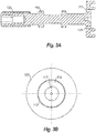
Fig. 3A is a cross-sectional side view of an embodiment of a spool in accordance with this disclosure; -
Fig. 3B is a front plan view of the spool ofFig. 3A , showing a cam line overlaid on the spool for reference; -
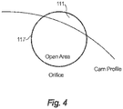
Fig. 4 is a schematic diagram indicating an open area of the plate orifice in a partially obstructed position by the cam surface; -
Fig. 5 is a cross-sectional view of an embodiment of a rotary adjustable plate orifice valve in accordance with this disclosure show having pressure applied through P1 and P2, with a net force leading into P1; and -
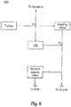
Fig. 6 shows a partial systematic view of a fuel system, showing an embodiment of a rotary adjustable plate orifice valve disposed therein. - Reference will now be made to the drawings wherein like reference numerals identify similar structural features or aspects of the subject disclosure. For purposes of explanation and illustration, and not limitation, an illustrative view of an embodiment of a rotary adjustable plate orifice valve in accordance with the disclosure is shown in
Fig. 1 and is designated generally byreference character 100. Other embodiments and/or aspects of this disclosure are shown inFigs. 2-6 . The systems and methods described herein can be used to regulate pressure between a first flow path (indicated by pressure "P1") and a second flow path (indicated by pressure "P2"). - Generally, in certain embodiments, a valve with a rotationally adjustable flow area can include a first member defining a first wall having a first opening therein, and a second member defining a second wall having a second opening therein, the first member being rotatable relative to the second member, and flow area through the valve being defined by fluidic communication between the first opening and the second opening that varies with relative rotational position between the first member and the second member.
- Referring to
Fig. 1 , embodiments of such a valve can include a rotary adjustableplate orifice valve 100, for example. Thevalve 100 can include ahousing 101 including a first fluid path opening 105 and a second fluid path opening 103. Referring additionally toFigs. 2A and 2B , asleeve 107 is disposed at least partially within thehousing 101. Thesleeve 107 includes a sleeve opening 109 defined by acam surface 111. In certain embodiments, thesleeve 107 can threadably engage with thehousing 101 as shown. - The
sleeve 107 can further includeradial openings 108 for receiving P1 pressure from the firstfluid path 105. A filter 110 (e.g., a last chance screen) can be disposed over theradial openings 108. - As shown in
Fig. 2B , thecam surface 111 can define a spiral shape. Any other suitable shape is contemplated herein. - Referring additionally to
Figs. 3A and 3B , thevalve 100 includes aspool 113 disposed at least partially within thesleeve 107 and thehousing 101. Thespool 113 is configured to rotate relative to thesleeve 107 and tohousing 101. Thespool 113 includes aplate face 115 that abuts thecam surface 111. Aplate orifice 117 is defined through theplate face 115 and can be positionable to vary between being in full unoccluded fluidic communication with theopening 109, being fully occluded from any fluidic communication with theopening 109 as well as being partially fluidic communication with theopening 109, depending upon a rotational orientation between thespool 113 and thesleeve 107. Theplate orifice 117 can be circular in cross-sectional shape. Any other suitable shape is contemplated herein (e.g., oval, square) as long as rotational interaction ofsleeve 107 and thecam surface 111 causes changes in total open flow area available for flow through theplate orifice 117. - As shown in
Fig. 3B , theplate orifice 117 is positioned at a 0 degree position, however, phantom positions are shown overlaid on an illustrative cam profile of thecam surface 111. In certain embodiments, theplate orifice 117 can be sized such that at no point of rotation is flow area smaller than a size that would cause clogging of the orifice 117 (e.g., no smaller than the smallest filter size in a fuel system). In certain embodiments, theorifice 117 can be sized to meet about 53 pph minimum of fuel flow at about 414 kPa (60 psid) at about 0°C (32F). - The
cam surface 111 can be shaped to allow adjustment of fuel flow down to 53 pph under all tolerance conditions, for example. In certain embodiments, thecam surface 111 may not close theorifice 117 past half open area. - The
spool 113 can include aface seal 119 disposed in theplate face 115 and in sealing communication with thehousing 101. In certain embodiments, aring seal 121 can be disposed around an outer diameter of thesleeve 107 and in sealing communication with thehousing 101. - The
spool 113 can include a threadedend 123 opposite theplate face 115. Alock nut 125 can be in threaded connection with the threadedend 123 of thespool 113. Thelock nut 125 can tighten theplate face 115 of thespool 113 against thecam surface 111 of thesleeve 107. - In certain embodiments, the
spool 113 can include a ring seal 127 disposed in sealing communication with an inner diameter of thesleeve 107. This ring seal 127 can prevent P1 from leaking to atmospheric pressure (e.g., during testing). In certain embodiments, thevalve 100 can include acap 129 configured to connect to thesleeve 107 at an opposite end relative to thecam surface 111 to cover the threadedend 123 of thespool 113 and thelock nut 125 disposed on the threadedend 123. - Referring additionally to
Fig. 4 , an amount of open area of theorifice 117 that is in fluid communication with thesleeve opening 109 changes as a function of a rotational position of theorifice 117 relative to thecam surface 111. Fluid can flow between the first fluid path P1 and the second fluid path P2 through theplate orifice 117. - Referring to
Fig. 5 , thevalve 100 is shown having a pressure P2, P1, and Pambient applied to the valve. As shown, the net force facilitates a sealing force between therotating plate 115 andsleeve 107. - Referring to
Fig. 6 , an embodiment of avalve 100 is shown disposed in afuel system 600. P1 branches can be filtered or unfiltered. In certain embodiments, flow from the first fluid path can be filtered flow according to filtration hierarchy for fuel control. - While embodiments above describe the
cam surface 111 as being on thesleeve 107, in certain embodiments, thecam surface 111 can be located on thespool 113 and theorifice 117 can be defined in thesleeve 107. Any other suitable rotational dependent valve scheme is contemplated herein. - In accordance with at least one aspect of this disclosure, a method can include rotating a spool of a valve such that a plate orifice defined in a plate face thereof is positioned relative to a cam surface of a sleeve at a predetermined rotational position to block a predetermined amount of flow area of the plate orifice. In certain embodiments, the method can include locking the spool in place after positioning the spool and the plate orifice in the predetermined rotational position. Locking the spool can include tightening a lock nut threadably engaged with a threaded end of the spool against an inner surface of the sleeve to compress the plate face of the spool against the cam surface.
- Embodiments include an adjustable orifice positioned between P1 and P2 to guarantee a minimum flow level into the P2 circuit to generate suitable actuator pressure from the WBV. Embodiments include an orifice defined in a rotating plate face of spool that rotates over a shaped window (e.g., the
opening 109 defined by the cam surface 111) to open up or decrease the open area of the orifice. The spool and sleeve can be pre-loaded together by a locking screw, which reduces the clearance of the leak path into the orifice, e.g., to improve accuracy as temperature changes. The spool can be locked in place once the orifice opening is adjusted to achieve a precise range of flow. - Embodiments include benefits such as the ability to meet filtration hierarchy, reduced leakage around minimum flow orifice, reduced sensitivity to rotation (increased ease of adjustability), reduced effect of edge breaks on flow accuracy, and smaller physical package size. Embodiments provide a robust, easy to adjust orifice.
- The methods and systems of the present disclosure, as described above and shown in the drawings, provide for valve systems with superior properties. While the apparatus and methods of the subject disclosure have been shown and described with reference to embodiments, those skilled in the art will readily appreciate that changes and/or modifications may be made thereto without departing from the scope of the invention as defined by the claims.
Claims (15)
- A rotary adjustable plate orifice valve, comprising:a housing (101) including a first fluid path (105) opening and a second fluid path opening (103);a sleeve (107) disposed at least partially within the housing and having a sleeve opening (109) defined by a cam surface (111); anda spool (113) disposed at least partially within the sleeve and the housing and configured to rotate relative to the sleeve, the spool including:a plate face (115) that abuts the cam surface; anda plate orifice (117) defined in the plate face and positioned to be partially in fluid communication with the opening and to be partially blocked by the cam surface, wherein an amount of open area of the orifice that is in fluid communication with the sleeve opening changes as a function of a rotational position of the orifice relative to the cam surface;wherein fluid can flow between the first fluid path and the second fluid path through the plate orifice.
- The valve of claim 1, wherein the sleeve further includes radial openings (108) for receiving pressure from the second fluid path at the sleeve opening.
- The valve of claim 2, wherein a filter is disposed over the radial openings (108).
- The valve of any preceding claim, wherein the cam surface (111) defines a spiral shape.
- The valve of any preceding claim, wherein the plate orifice is circular in cross-sectional shape.
- The valve of any preceding claim, wherein the spool includes a face seal (119) in sealing communication with the housing.
- The valve of any preceding claim, further comprising a ring seal (121) disposed around an outer diameter of the sleeve in sealing communication with the housing.
- The valve of any preceding claim, wherein the spool includes a threaded end (123) opposite the plate face.
- The valve of claim 8, further comprising a lock nut (125) in threaded connection with the threaded end of the spool and configured to tighten the plate face of the spool against the cam surface of the sleeve.
- The valve of claim 9, wherein the spool includes a ring seal (127) disposed in sealing communication with an inner diameter of the sleeve.
- The valve of claim 9, further comprising a cap (129) configured to connect to the sleeve at an opposite end relative to the cam surface to cover the threaded end of the spool and the lock nut disposed on the threaded end.
- A method, comprising:rotating a spool of a valve such that a plate orifice defined in a plate face thereof is positioned relative to a cam surface of a sleeve at a predetermined rotational position to block a predetermined amount of flow area of the plate orifice.
- The method of claim 12, further comprising locking the spool in place after position the spool and the plate orifice in the predetermined rotational position, and preferably wherein locking the spool includes tightening a lock nut threadably engaged with a threaded end of the spool against an inner surface of the sleeve to compress the plate face of the spool against the cam surface.
- A valve with a rotationally adjustable flow area, comprising:a first member defining a first wall having a first opening therein; anda second member defining a second wall having a second opening therein, the first member being rotatable relative to the second member, and flow area through the valve being defined by fluidic communication between the first opening and the second opening that varies with relative rotational position between the first member and the second member.
- The valve of claim 14, further comprising a housing including a first fluid path opening and a second fluid path opening, wherein the first member includes a sleeve disposed at least partially within the housing, wherein the first wall includes a cam surface, wherein the first opening is a sleeve opening defined by the cam surface, and wherein the second member includes a spool disposed at least partially within the sleeve and the housing and configured to rotate relative to the sleeve, wherein the second wall is a plate face of the spool that abuts the cam surface, and wherein the second opening includes a plate orifice defined in the plate face and positioned to be partially in fluid communication with the opening and to be partially blocked by the cam surface, wherein an amount of open area of the orifice that is in fluid communication with the sleeve opening changes as a function of a rotational position of the orifice relative to the cam surface.
Priority Applications (1)
| Application Number | Priority Date | Filing Date | Title |
|---|---|---|---|
| EP22164805.8A EP4036390A1 (en) | 2017-01-20 | 2018-01-19 | Rotary adjustable orifice plate valve |
Applications Claiming Priority (1)
| Application Number | Priority Date | Filing Date | Title |
|---|---|---|---|
| US15/411,836 US10371267B2 (en) | 2017-01-20 | 2017-01-20 | Rotary adjustable orifice plate valve |
Related Child Applications (1)
| Application Number | Title | Priority Date | Filing Date |
|---|---|---|---|
| EP22164805.8A Division EP4036390A1 (en) | 2017-01-20 | 2018-01-19 | Rotary adjustable orifice plate valve |
Publications (2)
| Publication Number | Publication Date |
|---|---|
| EP3351768A1 true EP3351768A1 (en) | 2018-07-25 |
| EP3351768B1 EP3351768B1 (en) | 2022-04-20 |
Family
ID=61022166
Family Applications (2)
| Application Number | Title | Priority Date | Filing Date |
|---|---|---|---|
| EP18152644.3A Active EP3351768B1 (en) | 2017-01-20 | 2018-01-19 | Rotary adjustable orifice plate valve |
| EP22164805.8A Withdrawn EP4036390A1 (en) | 2017-01-20 | 2018-01-19 | Rotary adjustable orifice plate valve |
Family Applications After (1)
| Application Number | Title | Priority Date | Filing Date |
|---|---|---|---|
| EP22164805.8A Withdrawn EP4036390A1 (en) | 2017-01-20 | 2018-01-19 | Rotary adjustable orifice plate valve |
Country Status (2)
| Country | Link |
|---|---|
| US (1) | US10371267B2 (en) |
| EP (2) | EP3351768B1 (en) |
Cited By (1)
| Publication number | Priority date | Publication date | Assignee | Title |
|---|---|---|---|---|
| CN112797208A (en) * | 2021-01-05 | 2021-05-14 | 绍兴泰格机电技术有限公司 | Novel speed limiting valve |
Families Citing this family (1)
| Publication number | Priority date | Publication date | Assignee | Title |
|---|---|---|---|---|
| US11927272B1 (en) * | 2022-12-13 | 2024-03-12 | Hamilton Sundstrand Corporation | Valves with multi-piece sleeves |
Citations (5)
| Publication number | Priority date | Publication date | Assignee | Title |
|---|---|---|---|---|
| GB1549789A (en) * | 1977-01-20 | 1979-08-08 | Paragon Plastics Ltd | Water taps |
| US20070180813A1 (en) * | 2006-02-03 | 2007-08-09 | Pickard Andrew C | Gas turbine engine fuel system with fuel metering valve |
| EP1903416A2 (en) * | 2006-09-19 | 2008-03-26 | Goodrich Control Systems Limited | Rotary metering valve arrangement |
| CN105909814A (en) * | 2016-06-17 | 2016-08-31 | 特技阀门集团有限公司 | Flow regulating valve |
| EP3081784A1 (en) * | 2015-04-14 | 2016-10-19 | Hamilton Sundstrand Corporation | Gas turbine fuel control system with shutoff feature and associated method |
Family Cites Families (9)
| Publication number | Priority date | Publication date | Assignee | Title |
|---|---|---|---|---|
| US1271359A (en) * | 1916-09-20 | 1918-07-02 | Edmund J Price | Air-intake regulator. |
| US4058289A (en) * | 1975-10-14 | 1977-11-15 | Hicks Glenn W | Faucet valve |
| US4617957A (en) * | 1983-07-25 | 1986-10-21 | Xomox Corporation | Rotary plug valve |
| EP2092950A3 (en) * | 2001-11-14 | 2009-09-02 | JMS Co., Ltd. | Three-way stopcock, and liquid transfusion tubing set or blood transfusion tubing set using the three-way stopcock |
| WO2006049842A1 (en) * | 2004-10-28 | 2006-05-11 | Pall Corporation | Valve |
| WO2008057596A2 (en) | 2006-11-08 | 2008-05-15 | Siemens Water Technologies Corp. | Rotary valve |
| US7458386B2 (en) * | 2006-12-30 | 2008-12-02 | Ningbo Wanan Co., Ltd. | Manual gas valve with natural/LP gas conversion capability |
| US8699179B1 (en) * | 2013-03-14 | 2014-04-15 | Western Digital Technologies, Inc. | Hermetically sealed disk drive with fill port valve |
| FR3003655B1 (en) | 2013-03-25 | 2016-10-21 | Kipopluie | DEVICE FOR MANAGING LIQUID FLOW |
-
2017
- 2017-01-20 US US15/411,836 patent/US10371267B2/en active Active
-
2018
- 2018-01-19 EP EP18152644.3A patent/EP3351768B1/en active Active
- 2018-01-19 EP EP22164805.8A patent/EP4036390A1/en not_active Withdrawn
Patent Citations (5)
| Publication number | Priority date | Publication date | Assignee | Title |
|---|---|---|---|---|
| GB1549789A (en) * | 1977-01-20 | 1979-08-08 | Paragon Plastics Ltd | Water taps |
| US20070180813A1 (en) * | 2006-02-03 | 2007-08-09 | Pickard Andrew C | Gas turbine engine fuel system with fuel metering valve |
| EP1903416A2 (en) * | 2006-09-19 | 2008-03-26 | Goodrich Control Systems Limited | Rotary metering valve arrangement |
| EP3081784A1 (en) * | 2015-04-14 | 2016-10-19 | Hamilton Sundstrand Corporation | Gas turbine fuel control system with shutoff feature and associated method |
| CN105909814A (en) * | 2016-06-17 | 2016-08-31 | 特技阀门集团有限公司 | Flow regulating valve |
Cited By (2)
| Publication number | Priority date | Publication date | Assignee | Title |
|---|---|---|---|---|
| CN112797208A (en) * | 2021-01-05 | 2021-05-14 | 绍兴泰格机电技术有限公司 | Novel speed limiting valve |
| CN112797208B (en) * | 2021-01-05 | 2023-03-10 | 绍兴泰格机电技术有限公司 | Speed limiting valve |
Also Published As
| Publication number | Publication date |
|---|---|
| EP3351768B1 (en) | 2022-04-20 |
| US20180209547A1 (en) | 2018-07-26 |
| US10371267B2 (en) | 2019-08-06 |
| EP4036390A1 (en) | 2022-08-03 |
Similar Documents
| Publication | Publication Date | Title |
|---|---|---|
| CN101018984B (en) | Devices for regulating the flow of media in heating and cooling systems | |
| US2668555A (en) | Excess flow cutoff valve with adjustable valve seat | |
| DE10309428B4 (en) | filter | |
| EP3351768B1 (en) | Rotary adjustable orifice plate valve | |
| US5227062A (en) | Adjustable flow control for fluid separation system comprising relatively moveable orifice plates | |
| GB2089479A (en) | Bypass valve and alarm assembly | |
| CA2955281C (en) | Control valve | |
| CN107654702B (en) | One-way valve | |
| WO2014135583A1 (en) | Valve having a leakage indicator | |
| US10024440B2 (en) | Fuel tank valve assembly | |
| DE102007026162A1 (en) | Pressure reducer with spar adjustment function used in drinking water systems in buildings, has adjustable indicator with scale, markings and pointers for showing detected pressure values and pressure values for optimum pressure regulation | |
| WO2023280517A1 (en) | Separating device with a separating element | |
| US5879544A (en) | Differential pressure indicator | |
| EP0156962B1 (en) | Expansion valve | |
| WO2016126839A1 (en) | Carburetor fuel control | |
| US3646906A (en) | Pressure indicator and surge control device | |
| EP2944852B1 (en) | Contamination resistant cartridge valve | |
| WO1991010852A1 (en) | Apparatus for measurement and control, respectively, of temperature and/or pressure | |
| US3526384A (en) | Fuel trimming valve | |
| EP1813846A2 (en) | Safety valve for fluids | |
| WO2017156172A1 (en) | Flow control valve | |
| CN108601999B (en) | Filter and method for checking the suitability of filter elements | |
| US4183812A (en) | Fluid filtering device | |
| EP4008844B1 (en) | Leakage protection arrangement | |
| US4471803A (en) | Flow limit shutoff valve |
Legal Events
| Date | Code | Title | Description |
|---|---|---|---|
| PUAI | Public reference made under article 153(3) epc to a published international application that has entered the european phase |
Free format text: ORIGINAL CODE: 0009012 |
|
| STAA | Information on the status of an ep patent application or granted ep patent |
Free format text: STATUS: THE APPLICATION HAS BEEN PUBLISHED |
|
| AK | Designated contracting states |
Kind code of ref document: A1 Designated state(s): AL AT BE BG CH CY CZ DE DK EE ES FI FR GB GR HR HU IE IS IT LI LT LU LV MC MK MT NL NO PL PT RO RS SE SI SK SM TR |
|
| AX | Request for extension of the european patent |
Extension state: BA ME |
|
| RIN1 | Information on inventor provided before grant (corrected) |
Inventor name: BALLARD, PETER M. Inventor name: CORETTO, AUGUST M. Inventor name: RICKIS, AARON |
|
| STAA | Information on the status of an ep patent application or granted ep patent |
Free format text: STATUS: REQUEST FOR EXAMINATION WAS MADE |
|
| 17P | Request for examination filed |
Effective date: 20190125 |
|
| RBV | Designated contracting states (corrected) |
Designated state(s): AL AT BE BG CH CY CZ DE DK EE ES FI FR GB GR HR HU IE IS IT LI LT LU LV MC MK MT NL NO PL PT RO RS SE SI SK SM TR |
|
| STAA | Information on the status of an ep patent application or granted ep patent |
Free format text: STATUS: EXAMINATION IS IN PROGRESS |
|
| 17Q | First examination report despatched |
Effective date: 20200325 |
|
| GRAP | Despatch of communication of intention to grant a patent |
Free format text: ORIGINAL CODE: EPIDOSNIGR1 |
|
| STAA | Information on the status of an ep patent application or granted ep patent |
Free format text: STATUS: GRANT OF PATENT IS INTENDED |
|
| INTG | Intention to grant announced |
Effective date: 20211110 |
|
| GRAS | Grant fee paid |
Free format text: ORIGINAL CODE: EPIDOSNIGR3 |
|
| GRAA | (expected) grant |
Free format text: ORIGINAL CODE: 0009210 |
|
| STAA | Information on the status of an ep patent application or granted ep patent |
Free format text: STATUS: THE PATENT HAS BEEN GRANTED |
|
| AK | Designated contracting states |
Kind code of ref document: B1 Designated state(s): AL AT BE BG CH CY CZ DE DK EE ES FI FR GB GR HR HU IE IS IT LI LT LU LV MC MK MT NL NO PL PT RO RS SE SI SK SM TR |
|
| REG | Reference to a national code |
Ref country code: GB Ref legal event code: FG4D |
|
| REG | Reference to a national code |
Ref country code: CH Ref legal event code: EP |
|
| REG | Reference to a national code |
Ref country code: IE Ref legal event code: FG4D |
|
| REG | Reference to a national code |
Ref country code: DE Ref legal event code: R096 Ref document number: 602018033998 Country of ref document: DE |
|
| REG | Reference to a national code |
Ref country code: AT Ref legal event code: REF Ref document number: 1485316 Country of ref document: AT Kind code of ref document: T Effective date: 20220515 |
|
| REG | Reference to a national code |
Ref country code: LT Ref legal event code: MG9D |
|
| REG | Reference to a national code |
Ref country code: NL Ref legal event code: MP Effective date: 20220420 |
|
| REG | Reference to a national code |
Ref country code: AT Ref legal event code: MK05 Ref document number: 1485316 Country of ref document: AT Kind code of ref document: T Effective date: 20220420 |
|
| PG25 | Lapsed in a contracting state [announced via postgrant information from national office to epo] |
Ref country code: NL Free format text: LAPSE BECAUSE OF FAILURE TO SUBMIT A TRANSLATION OF THE DESCRIPTION OR TO PAY THE FEE WITHIN THE PRESCRIBED TIME-LIMIT Effective date: 20220420 |
|
| PG25 | Lapsed in a contracting state [announced via postgrant information from national office to epo] |
Ref country code: SE Free format text: LAPSE BECAUSE OF FAILURE TO SUBMIT A TRANSLATION OF THE DESCRIPTION OR TO PAY THE FEE WITHIN THE PRESCRIBED TIME-LIMIT Effective date: 20220420 Ref country code: PT Free format text: LAPSE BECAUSE OF FAILURE TO SUBMIT A TRANSLATION OF THE DESCRIPTION OR TO PAY THE FEE WITHIN THE PRESCRIBED TIME-LIMIT Effective date: 20220822 Ref country code: NO Free format text: LAPSE BECAUSE OF FAILURE TO SUBMIT A TRANSLATION OF THE DESCRIPTION OR TO PAY THE FEE WITHIN THE PRESCRIBED TIME-LIMIT Effective date: 20220720 Ref country code: LT Free format text: LAPSE BECAUSE OF FAILURE TO SUBMIT A TRANSLATION OF THE DESCRIPTION OR TO PAY THE FEE WITHIN THE PRESCRIBED TIME-LIMIT Effective date: 20220420 Ref country code: HR Free format text: LAPSE BECAUSE OF FAILURE TO SUBMIT A TRANSLATION OF THE DESCRIPTION OR TO PAY THE FEE WITHIN THE PRESCRIBED TIME-LIMIT Effective date: 20220420 Ref country code: GR Free format text: LAPSE BECAUSE OF FAILURE TO SUBMIT A TRANSLATION OF THE DESCRIPTION OR TO PAY THE FEE WITHIN THE PRESCRIBED TIME-LIMIT Effective date: 20220721 Ref country code: FI Free format text: LAPSE BECAUSE OF FAILURE TO SUBMIT A TRANSLATION OF THE DESCRIPTION OR TO PAY THE FEE WITHIN THE PRESCRIBED TIME-LIMIT Effective date: 20220420 Ref country code: ES Free format text: LAPSE BECAUSE OF FAILURE TO SUBMIT A TRANSLATION OF THE DESCRIPTION OR TO PAY THE FEE WITHIN THE PRESCRIBED TIME-LIMIT Effective date: 20220420 Ref country code: BG Free format text: LAPSE BECAUSE OF FAILURE TO SUBMIT A TRANSLATION OF THE DESCRIPTION OR TO PAY THE FEE WITHIN THE PRESCRIBED TIME-LIMIT Effective date: 20220720 Ref country code: AT Free format text: LAPSE BECAUSE OF FAILURE TO SUBMIT A TRANSLATION OF THE DESCRIPTION OR TO PAY THE FEE WITHIN THE PRESCRIBED TIME-LIMIT Effective date: 20220420 |
|
| PG25 | Lapsed in a contracting state [announced via postgrant information from national office to epo] |
Ref country code: RS Free format text: LAPSE BECAUSE OF FAILURE TO SUBMIT A TRANSLATION OF THE DESCRIPTION OR TO PAY THE FEE WITHIN THE PRESCRIBED TIME-LIMIT Effective date: 20220420 Ref country code: PL Free format text: LAPSE BECAUSE OF FAILURE TO SUBMIT A TRANSLATION OF THE DESCRIPTION OR TO PAY THE FEE WITHIN THE PRESCRIBED TIME-LIMIT Effective date: 20220420 Ref country code: LV Free format text: LAPSE BECAUSE OF FAILURE TO SUBMIT A TRANSLATION OF THE DESCRIPTION OR TO PAY THE FEE WITHIN THE PRESCRIBED TIME-LIMIT Effective date: 20220420 Ref country code: IS Free format text: LAPSE BECAUSE OF FAILURE TO SUBMIT A TRANSLATION OF THE DESCRIPTION OR TO PAY THE FEE WITHIN THE PRESCRIBED TIME-LIMIT Effective date: 20220820 |
|
| REG | Reference to a national code |
Ref country code: DE Ref legal event code: R097 Ref document number: 602018033998 Country of ref document: DE |
|
| PG25 | Lapsed in a contracting state [announced via postgrant information from national office to epo] |
Ref country code: SM Free format text: LAPSE BECAUSE OF FAILURE TO SUBMIT A TRANSLATION OF THE DESCRIPTION OR TO PAY THE FEE WITHIN THE PRESCRIBED TIME-LIMIT Effective date: 20220420 Ref country code: SK Free format text: LAPSE BECAUSE OF FAILURE TO SUBMIT A TRANSLATION OF THE DESCRIPTION OR TO PAY THE FEE WITHIN THE PRESCRIBED TIME-LIMIT Effective date: 20220420 Ref country code: RO Free format text: LAPSE BECAUSE OF FAILURE TO SUBMIT A TRANSLATION OF THE DESCRIPTION OR TO PAY THE FEE WITHIN THE PRESCRIBED TIME-LIMIT Effective date: 20220420 Ref country code: EE Free format text: LAPSE BECAUSE OF FAILURE TO SUBMIT A TRANSLATION OF THE DESCRIPTION OR TO PAY THE FEE WITHIN THE PRESCRIBED TIME-LIMIT Effective date: 20220420 Ref country code: DK Free format text: LAPSE BECAUSE OF FAILURE TO SUBMIT A TRANSLATION OF THE DESCRIPTION OR TO PAY THE FEE WITHIN THE PRESCRIBED TIME-LIMIT Effective date: 20220420 Ref country code: CZ Free format text: LAPSE BECAUSE OF FAILURE TO SUBMIT A TRANSLATION OF THE DESCRIPTION OR TO PAY THE FEE WITHIN THE PRESCRIBED TIME-LIMIT Effective date: 20220420 |
|
| PLBE | No opposition filed within time limit |
Free format text: ORIGINAL CODE: 0009261 |
|
| STAA | Information on the status of an ep patent application or granted ep patent |
Free format text: STATUS: NO OPPOSITION FILED WITHIN TIME LIMIT |
|
| 26N | No opposition filed |
Effective date: 20230123 |
|
| PG25 | Lapsed in a contracting state [announced via postgrant information from national office to epo] |
Ref country code: AL Free format text: LAPSE BECAUSE OF FAILURE TO SUBMIT A TRANSLATION OF THE DESCRIPTION OR TO PAY THE FEE WITHIN THE PRESCRIBED TIME-LIMIT Effective date: 20220420 |
|
| PG25 | Lapsed in a contracting state [announced via postgrant information from national office to epo] |
Ref country code: SI Free format text: LAPSE BECAUSE OF FAILURE TO SUBMIT A TRANSLATION OF THE DESCRIPTION OR TO PAY THE FEE WITHIN THE PRESCRIBED TIME-LIMIT Effective date: 20220420 |
|
| P01 | Opt-out of the competence of the unified patent court (upc) registered |
Effective date: 20230522 |
|
| REG | Reference to a national code |
Ref country code: CH Ref legal event code: PL |
|
| PG25 | Lapsed in a contracting state [announced via postgrant information from national office to epo] |
Ref country code: LU Free format text: LAPSE BECAUSE OF NON-PAYMENT OF DUE FEES Effective date: 20230119 |
|
| REG | Reference to a national code |
Ref country code: BE Ref legal event code: MM Effective date: 20230131 |
|
| PG25 | Lapsed in a contracting state [announced via postgrant information from national office to epo] |
Ref country code: LI Free format text: LAPSE BECAUSE OF NON-PAYMENT OF DUE FEES Effective date: 20230131 Ref country code: CH Free format text: LAPSE BECAUSE OF NON-PAYMENT OF DUE FEES Effective date: 20230131 |
|
| PG25 | Lapsed in a contracting state [announced via postgrant information from national office to epo] |
Ref country code: BE Free format text: LAPSE BECAUSE OF NON-PAYMENT OF DUE FEES Effective date: 20230131 |
|
| PG25 | Lapsed in a contracting state [announced via postgrant information from national office to epo] |
Ref country code: IT Free format text: LAPSE BECAUSE OF FAILURE TO SUBMIT A TRANSLATION OF THE DESCRIPTION OR TO PAY THE FEE WITHIN THE PRESCRIBED TIME-LIMIT Effective date: 20220420 Ref country code: IE Free format text: LAPSE BECAUSE OF NON-PAYMENT OF DUE FEES Effective date: 20230119 |
|
| PG25 | Lapsed in a contracting state [announced via postgrant information from national office to epo] |
Ref country code: MC Free format text: LAPSE BECAUSE OF FAILURE TO SUBMIT A TRANSLATION OF THE DESCRIPTION OR TO PAY THE FEE WITHIN THE PRESCRIBED TIME-LIMIT Effective date: 20220420 |
|
| PG25 | Lapsed in a contracting state [announced via postgrant information from national office to epo] |
Ref country code: MC Free format text: LAPSE BECAUSE OF FAILURE TO SUBMIT A TRANSLATION OF THE DESCRIPTION OR TO PAY THE FEE WITHIN THE PRESCRIBED TIME-LIMIT Effective date: 20220420 |
|
| PG25 | Lapsed in a contracting state [announced via postgrant information from national office to epo] |
Ref country code: BG Free format text: LAPSE BECAUSE OF FAILURE TO SUBMIT A TRANSLATION OF THE DESCRIPTION OR TO PAY THE FEE WITHIN THE PRESCRIBED TIME-LIMIT Effective date: 20220420 |
|
| PG25 | Lapsed in a contracting state [announced via postgrant information from national office to epo] |
Ref country code: BG Free format text: LAPSE BECAUSE OF FAILURE TO SUBMIT A TRANSLATION OF THE DESCRIPTION OR TO PAY THE FEE WITHIN THE PRESCRIBED TIME-LIMIT Effective date: 20220420 |
|
| PG25 | Lapsed in a contracting state [announced via postgrant information from national office to epo] |
Ref country code: CY Free format text: LAPSE BECAUSE OF FAILURE TO SUBMIT A TRANSLATION OF THE DESCRIPTION OR TO PAY THE FEE WITHIN THE PRESCRIBED TIME-LIMIT; INVALID AB INITIO Effective date: 20180119 |
|
| PG25 | Lapsed in a contracting state [announced via postgrant information from national office to epo] |
Ref country code: HU Free format text: LAPSE BECAUSE OF FAILURE TO SUBMIT A TRANSLATION OF THE DESCRIPTION OR TO PAY THE FEE WITHIN THE PRESCRIBED TIME-LIMIT; INVALID AB INITIO Effective date: 20180119 |
|
| PG25 | Lapsed in a contracting state [announced via postgrant information from national office to epo] |
Ref country code: TR Free format text: LAPSE BECAUSE OF FAILURE TO SUBMIT A TRANSLATION OF THE DESCRIPTION OR TO PAY THE FEE WITHIN THE PRESCRIBED TIME-LIMIT Effective date: 20220420 |
|
| PGFP | Annual fee paid to national office [announced via postgrant information from national office to epo] |
Ref country code: GB Payment date: 20251220 Year of fee payment: 9 |
|
| PGFP | Annual fee paid to national office [announced via postgrant information from national office to epo] |
Ref country code: FR Payment date: 20251217 Year of fee payment: 9 |
|
| PGFP | Annual fee paid to national office [announced via postgrant information from national office to epo] |
Ref country code: DE Payment date: 20251217 Year of fee payment: 9 |