EP3351745A1 - Emergency shut-off device - Google Patents
Emergency shut-off device Download PDFInfo
- Publication number
- EP3351745A1 EP3351745A1 EP15910727.5A EP15910727A EP3351745A1 EP 3351745 A1 EP3351745 A1 EP 3351745A1 EP 15910727 A EP15910727 A EP 15910727A EP 3351745 A1 EP3351745 A1 EP 3351745A1
- Authority
- EP
- European Patent Office
- Prior art keywords
- piston
- trip
- control oil
- emergency
- emergency shut
- Prior art date
- Legal status (The legal status is an assumption and is not a legal conclusion. Google has not performed a legal analysis and makes no representation as to the accuracy of the status listed.)
- Withdrawn
Links
- 239000010802 sludge Substances 0.000 abstract description 7
- 230000015572 biosynthetic process Effects 0.000 abstract 1
- 230000002401 inhibitory effect Effects 0.000 abstract 1
- 238000010586 diagram Methods 0.000 description 10
- 230000007423 decrease Effects 0.000 description 4
- 238000012986 modification Methods 0.000 description 4
- 230000004048 modification Effects 0.000 description 4
- 230000000694 effects Effects 0.000 description 2
- 239000000470 constituent Substances 0.000 description 1
- 230000006866 deterioration Effects 0.000 description 1
- 230000002542 deteriorative effect Effects 0.000 description 1
- 238000000605 extraction Methods 0.000 description 1
- 230000003252 repetitive effect Effects 0.000 description 1
Images






Classifications
-
- F—MECHANICAL ENGINEERING; LIGHTING; HEATING; WEAPONS; BLASTING
- F01—MACHINES OR ENGINES IN GENERAL; ENGINE PLANTS IN GENERAL; STEAM ENGINES
- F01D—NON-POSITIVE DISPLACEMENT MACHINES OR ENGINES, e.g. STEAM TURBINES
- F01D21/00—Shutting-down of machines or engines, e.g. in emergency; Regulating, controlling, or safety means not otherwise provided for
-
- F—MECHANICAL ENGINEERING; LIGHTING; HEATING; WEAPONS; BLASTING
- F01—MACHINES OR ENGINES IN GENERAL; ENGINE PLANTS IN GENERAL; STEAM ENGINES
- F01D—NON-POSITIVE DISPLACEMENT MACHINES OR ENGINES, e.g. STEAM TURBINES
- F01D21/00—Shutting-down of machines or engines, e.g. in emergency; Regulating, controlling, or safety means not otherwise provided for
- F01D21/003—Arrangements for testing or measuring
-
- F—MECHANICAL ENGINEERING; LIGHTING; HEATING; WEAPONS; BLASTING
- F01—MACHINES OR ENGINES IN GENERAL; ENGINE PLANTS IN GENERAL; STEAM ENGINES
- F01D—NON-POSITIVE DISPLACEMENT MACHINES OR ENGINES, e.g. STEAM TURBINES
- F01D21/00—Shutting-down of machines or engines, e.g. in emergency; Regulating, controlling, or safety means not otherwise provided for
- F01D21/16—Trip gear
-
- F—MECHANICAL ENGINEERING; LIGHTING; HEATING; WEAPONS; BLASTING
- F01—MACHINES OR ENGINES IN GENERAL; ENGINE PLANTS IN GENERAL; STEAM ENGINES
- F01D—NON-POSITIVE DISPLACEMENT MACHINES OR ENGINES, e.g. STEAM TURBINES
- F01D21/00—Shutting-down of machines or engines, e.g. in emergency; Regulating, controlling, or safety means not otherwise provided for
- F01D21/16—Trip gear
- F01D21/18—Trip gear involving hydraulic means
-
- F—MECHANICAL ENGINEERING; LIGHTING; HEATING; WEAPONS; BLASTING
- F01—MACHINES OR ENGINES IN GENERAL; ENGINE PLANTS IN GENERAL; STEAM ENGINES
- F01D—NON-POSITIVE DISPLACEMENT MACHINES OR ENGINES, e.g. STEAM TURBINES
- F01D17/00—Regulating or controlling by varying flow
- F01D17/10—Final actuators
- F01D17/12—Final actuators arranged in stator parts
- F01D17/14—Final actuators arranged in stator parts varying effective cross-sectional area of nozzles or guide conduits
- F01D17/141—Final actuators arranged in stator parts varying effective cross-sectional area of nozzles or guide conduits by means of shiftable members or valves obturating part of the flow path
- F01D17/145—Final actuators arranged in stator parts varying effective cross-sectional area of nozzles or guide conduits by means of shiftable members or valves obturating part of the flow path by means of valves, e.g. for steam turbines
-
- F—MECHANICAL ENGINEERING; LIGHTING; HEATING; WEAPONS; BLASTING
- F05—INDEXING SCHEMES RELATING TO ENGINES OR PUMPS IN VARIOUS SUBCLASSES OF CLASSES F01-F04
- F05D—INDEXING SCHEME FOR ASPECTS RELATING TO NON-POSITIVE-DISPLACEMENT MACHINES OR ENGINES, GAS-TURBINES OR JET-PROPULSION PLANTS
- F05D2220/00—Application
- F05D2220/30—Application in turbines
- F05D2220/31—Application in turbines in steam turbines
-
- F—MECHANICAL ENGINEERING; LIGHTING; HEATING; WEAPONS; BLASTING
- F05—INDEXING SCHEMES RELATING TO ENGINES OR PUMPS IN VARIOUS SUBCLASSES OF CLASSES F01-F04
- F05D—INDEXING SCHEME FOR ASPECTS RELATING TO NON-POSITIVE-DISPLACEMENT MACHINES OR ENGINES, GAS-TURBINES OR JET-PROPULSION PLANTS
- F05D2270/00—Control
- F05D2270/01—Purpose of the control system
- F05D2270/02—Purpose of the control system to control rotational speed (n)
- F05D2270/021—Purpose of the control system to control rotational speed (n) to prevent overspeed
-
- F—MECHANICAL ENGINEERING; LIGHTING; HEATING; WEAPONS; BLASTING
- F05—INDEXING SCHEMES RELATING TO ENGINES OR PUMPS IN VARIOUS SUBCLASSES OF CLASSES F01-F04
- F05D—INDEXING SCHEME FOR ASPECTS RELATING TO NON-POSITIVE-DISPLACEMENT MACHINES OR ENGINES, GAS-TURBINES OR JET-PROPULSION PLANTS
- F05D2270/00—Control
- F05D2270/01—Purpose of the control system
- F05D2270/09—Purpose of the control system to cope with emergencies
- F05D2270/091—Purpose of the control system to cope with emergencies in particular sudden load loss
-
- F—MECHANICAL ENGINEERING; LIGHTING; HEATING; WEAPONS; BLASTING
- F16—ENGINEERING ELEMENTS AND UNITS; GENERAL MEASURES FOR PRODUCING AND MAINTAINING EFFECTIVE FUNCTIONING OF MACHINES OR INSTALLATIONS; THERMAL INSULATION IN GENERAL
- F16K—VALVES; TAPS; COCKS; ACTUATING-FLOATS; DEVICES FOR VENTING OR AERATING
- F16K31/00—Actuating devices; Operating means; Releasing devices
- F16K31/44—Mechanical actuating means
- F16K31/52—Mechanical actuating means with crank, eccentric, or cam
- F16K31/524—Mechanical actuating means with crank, eccentric, or cam with a cam
- F16K31/52475—Mechanical actuating means with crank, eccentric, or cam with a cam comprising a sliding valve
- F16K31/52483—Mechanical actuating means with crank, eccentric, or cam with a cam comprising a sliding valve comprising a multiple-way sliding valve
-
- Y—GENERAL TAGGING OF NEW TECHNOLOGICAL DEVELOPMENTS; GENERAL TAGGING OF CROSS-SECTIONAL TECHNOLOGIES SPANNING OVER SEVERAL SECTIONS OF THE IPC; TECHNICAL SUBJECTS COVERED BY FORMER USPC CROSS-REFERENCE ART COLLECTIONS [XRACs] AND DIGESTS
- Y10—TECHNICAL SUBJECTS COVERED BY FORMER USPC
- Y10T—TECHNICAL SUBJECTS COVERED BY FORMER US CLASSIFICATION
- Y10T137/00—Fluid handling
- Y10T137/8593—Systems
- Y10T137/86493—Multi-way valve unit
- Y10T137/86574—Supply and exhaust
- Y10T137/8667—Reciprocating valve
- Y10T137/86694—Piston valve
- Y10T137/8671—With annular passage [e.g., spool]
Definitions
- the present invention relates to an emergency shut-off device for urgently stopping a steam turbine.
- An emergency shut-off device is installed to immediately close the trip-and-throttle valve (hereinafter called the TTV) to urgently stop a steam turbine in case of an emergency in which a problem (such as an overspeed, an excessive shaft vibration, or the like) which prevents safe operation of the steam turbine has occurred.
- TTV trip-and-throttle valve
- Fig. 10 illustrates a conventional emergency shut-off device
- Fig. 11 and 12 illustrate a trip system including the conventional emergency shut-off device.
- Fig. 11 illustrates a state in normal operation (during operation of a steam turbine)
- Fig. 12 illustrates a state at the time of tripping.
- the trip system illustrated in Figs. 11 and 12 supplies and drains control oil to and from a TTV 31 and a governor valve (hereinafter called the GV) 32 of the steam turbine (not illustrated), using an emergency shut-off device 10B.
- the GV governor valve
- the emergency shut-off device 10B includes a trip piston 12 and a trip pilot valve 17 disposed in parallel with each other inside a cylinder 11.
- An end rod 13b on one end side (the left side in the figure) of a rod 13a of the trip piston 12 passes through the cylinder 11 and is exposed to the outside.
- a trip button 13c Provided at the end of the end rod 13b is a trip button 13c.
- a piston valve 14 Provided on the other end side (the right side in the figure) of the rod 13a is a piston valve 14, from which an end rod 13d extends.
- the end rod 13d passes through the cylinder 11 and is exposed to the outside.
- the end of the end rod 13d is in contact with a lever portion 16a of a cam 16.
- the rod 13a is provided with a spring 15 which applies a biasing force to the rod 13a in the direction toward the cam 16.
- An end rod 18b on one end side (the left side in the figure) of a rod 18a of the trip pilot valve 17 also passes through the cylinder 11 and is exposed to the outside.
- a reset button 18c Provided at the end of the end rod 18b is a reset button 18c.
- the rod 18a is provided with multiple piston valves 19 to 21 spaced at predetermined intervals.
- An end rod 18d on the other side (the right side in the figure) of the rod 18a also extends from the piston valve 21, passes through the cylinder 11, and is exposed to the outside.
- the end of the end rod 18d is in contact with a latch portion 16b of the cam 16.
- the end rod 18b is provided with a spring 22 which applies a biasing force to the end rod 18b in the direction toward the cam 16.
- the cylinder 11 has a port 23 on the trip piston 12 side, and the piston valve 14 forms a chamber 24.
- the cylinder 11 also has ports 25a to 25f on the trip pilot valve 17 side.
- the piston valve 19 forms a chamber 26a
- the piston valve 19 and the piston valve 20 form a chamber 26b
- the piston valve 20 and the piston valve 21 form a chamber 26c
- the piston valve 21 forms a chamber 26d.
- the control oil is supplied to and drained from the chamber 24 via the port 23.
- air is discharged or the control oil is drained from the inside of the chamber 26a via the port 25a
- air is discharged or the control oil is drained from the chamber 26a or the chamber 26b via the port 25b
- the control oil is supplied to and drained from the chamber 26b (supplied to and drained from the GV 32) via the port 25c
- the control oil is supplied to the chamber 26b or the chamber 26c via the port 25d
- the control oil is supplied to and drained from the chamber 26c (supplied to and drained from the TTV 31) via the port 25e
- air is discharged or the control oil is drained from the chamber 26c or the chamber 26d via the port 25f.
- a pipe for supplying the control oil from the supply source of the control oil is connected to the port 25d and also connected to the port 23 via an orifice 34.
- a pipe for supplying and draining the control oil to and from the GV 32 is connected to the port 25c, and a pipe for supplying and draining the control oil to and from the TTV 31 is connected to the port 25e.
- each drainage line includes a valve 36, a valve 37 and orifice 38 connected in parallel with the valve 36, and a solenoid valve 39 connected downstream (on the draining side) of the valve 36, valve 37, and orifice 38.
- the chamber 24 is under hydraulic pressure via the orifice 34, and the hydraulic pressure of the chamber 24 opposes the biasing force of the spring 15, which prevents the trip piston 12 from moving toward the cam 16. Accordingly, the latch portion 16b of the cam 16 also prevents the trip pilot valve 17 from moving toward the cam 16.
- control oil supplied to the port 25d is then supplied to the TTV 31 via the chamber 26c and the port 25e.
- the control oil from the GV 32 is drained via the port 25c, the chamber 26b, and the port 25b.
- control oil supplied to the port 25d is then suppled to the GV 32 via the chamber 26b and the port 25c.
- the control oil from the TTV 31 is drained via the port 25e, the chamber 26c, and the port 25f.
- the control oil and the springs 15 and 22 are used to operate the trip piston 12 and the trip pilot valve 17.
- the sludge may clog the sliding surfaces (portions indicated with symbols A in Fig. 10 ) of the piston valves 14, and 19 to 21, and cause the trip piston 12 and the trip pilot valve 17 to adhere to the cylinder 11, preventing them from moving.
- the present invention has been made in view of the above problem, and an object thereof is to provide an emergency shut-off device capable of preventing the occurrence of sludge to achieve reliable operation.
- an emergency shut-off device which shuts off supply of control oil to a trip-and-throttle valve of a steam turbine and closes the trip-and-throttle valve in an emergency
- the emergency shut-off device comprising: a cylinder; a piston which slides in the cylinder; a spring which applies a biasing force to the piston; a plurality of piston valves disposed on the piston; and a plurality of chambers which are formed by the piston valves, and which the control oil is supplied to and drained from, wherein a sliding surface of each of the piston valves has a groove to leak the control oil in the chambers.
- an emergency shut-off device is the emergency shut-off device according to the first aspect of the invention, wherein the groove is a spiral groove formed on the sliding surface of each of the piston valves.
- an emergency shut-off device is the emergency shut-off device according to the first aspect of the invention, wherein the groove is a linear groove formed on the sliding surface of each of the piston valves and extending along an axis direction of the piston.
- an emergency shut-off device is the emergency shut-off device according to any one of the first to third aspects of the invention, wherein a depth of the groove is 1.0 mm or less.
- an emergency shut-off device is the emergency shut-off device according to any one of the first to fourth aspects of the invention, wherein the piston includes a first piston and a second piston which, when the first piston moves from a position in normal operation to a position in the emergency, moves from a position in the normal operation to a position in the emergency in an interlocked fashion, and the chambers include at least a movement chamber which is formed by the piston valve of the first piston and drains the control oil in the emergency to move the first piston from the position in the normal operation to the position in the emergency and a trip-and-throttle valve chamber which is formed by the piston valve of the second piston, supplies the control oil to the trip-and-throttle valve when the second piston is at the position in the normal operation, and drains the control oil from the trip-and-throttle valve when the second piston is at the position in the emergency.
- the present invention prevents the occurrence of sludge to achieve reliable operation, and thus improves the reliability of the trip operation of the trip-and-throttle valve.
- FIG. 1 A trip system having an emergency shut-off device according to this example is illustrated in Fig. 1 .
- the emergency shut-off device 10A according to this example basically has substantially the same configuration as that of the conventional emergency shut-off device 10B illustrated in Figs. 10 to 12 , and a trip system having the emergency shut-off device 10A also has almost the same configuration as that of the conventional emergency shut-off device 10B.
- the same constitutes are denoted by the same symbols, and repetitive descriptions thereof are omitted.
- the trip system illustrated in Fig. 1 supplies and drains control oil to and from a TTV 31 and a GV 32 of a steam turbine (not illustrated) using the emergency shut-off device 10A according to this example, and shuts off the supply of the control oil to close the TTV 31 in an emergency (trip operation) .
- Fig. 1 illustrates the trip system during the normal operation (during the operation of the steam turbine), this trip system gets into the same state as that of the trip system illustrated in Fig. 12 at the time of tripping.
- the emergency shut-off device 10A includes as constituents a cylinder 11; a trip piston 12 (first piston) and a trip pilot valve 17 (second piston) which are pistons sliding in the cylinder 11; springs 15 and 22 applying biasing forces to the trip piston 12 and the trip pilot valve 17; piston valves 14, and 19 to 21 disposed on the trip piston 12 and the trip pilot valve 17; and chambers 24, and 26a to 26d formed by the piston valves 14, and 19 to 21, and through which control oil is supplied and drained.
- the chamber 24 (movement chamber) is formed by the piston valve 14 of the trip piston 12.
- the chamber 26b (governor valve chamber) is formed by the piston valve 19 and the piston valve 20 of the trip pilot valve 17.
- the chamber 26b connects a port 25b and a port 25c to each other to drain the control oil from the GV 32.
- the chamber 26b connects the port 25c and a port 25d to each other to supply the control oil to the GV 32 (see Fig. 12 ).
- the chamber 26c (trip-and-throttle valve chamber) is formed by the piston valve 20 and the piston valve 21 of the trip pilot valve 17.
- the chamber 26c connects the port 25d and a port 25e to supply the control oil to the TTV 31.
- the chamber 26c connects the port 25e and a port 25f to each other to drain the control oil from the TTV 31 (see Fig. 12 ). Note that the chambers 26a and 26d drain the control oil or discharge air along with the movement of the trip pilot valve 17.
- the control oil used in the emergency shut-off device 10A of such a trip system may stagnate or deteriorate, and cause sludge, which clogs the sliding surfaces of the piston valves 14, and 19 to 21 of the trip piston 12 and the trip pilot valve 17 and causes them to adhere to the cylinder 11, resulting in malfunctioning.
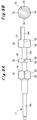
- each of the piston valves 14, and 19 to 21 has a spiral groove 51 formed on the sliding surface thereof as if the spiral groove 51 is wound around the sliding surface.
- Fig. 4 is an enlarged view of a portion of the sliding surface of the piston valve 14 illustrated in Fig 2 .
- This spiral groove 51 is used to intentionally keep leaking a small amount of the control oil to prevent the control oil from stagnating or deteriorating, and thus preventing the occurrence of sludge.
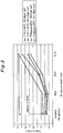
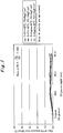
- Graphs illustrated in Figs. 5 to 7 show the comparison between the result of a test performed with a trip system having the conventional emergency shut-off device 10B and the result of a test performed with a trip system having the emergency shut-off device 10A according to this example.
- the data indicated by "Original” in Figs. 5 to 7 are the results of the test performed with the trip system having the conventional emergency shut-off device 10B.
- the sliding surface of each of the piston valves 14, and 19 to 21 does not have a groove.
- Fig. 6 indicates P1/PO ⁇ 100 as the amount of decrease in the pressure P1 based on the above P0 and the pressure P1 measured with pressure gauges 42 illustrated in Fig. 1
- Fig. 7 indicates P2/P0 ⁇ 100 as the amount of decrease in the pressure P2 based on the above P0 and the pressure P2 measured with a pressure gauge 43 illustrated in Fig. 1 . Note that as illustrated in Fig.
- the pressure gauges 42 are disposed on pipes in a drain device 35 (each between a valve 36 and orifice 38 and a solenoid valve 39), and the pressure gauge 43 is disposed on a pipe between the emergency shut-off device 10A and the TTV 31.
- the deeper the groove is (the larger the radius R is), the larger the leakage amount of the control oil is.
- the leakage amount of the control oil is about three times that of "Original” (no groove).
- the depth R of the spiral groove 51 is about 1.0 mm or less, the pressure loss between before and after the emergency shut-off device 10A can be suppressed to be smaller than or equal to 1%. In other words, the depth R of the spiral groove 51 only needs to be 1.0 mm or less.
- multiple linear grooves 52 extending along the axis direction of the rod 13a may be formed on the sliding surface of the piston valve 14, and as illustrated in Figs. 9A and 9B , multiple linear grooves 52 extending along the axis direction of the rod 18a may be formed on the sliding surface of each of the piston valves 19 to 21.
- 19 to 21 are formed four linear grooves 52 at intervals of 90°.
- the linear grooves 52 illustrated in Figs. 8A, 8B , 9A and 9B also provide the same effects as those of the spiral groove 51 illustrated in Figs. 2 and 3 .
- spiral groove 51 and the linear grooves 52 may be combined such that some piston valves have the spiral groove 51, and the other piston valves have the linear grooves. Further, the spiral grooves 51 and the liner grooves 52 may have different depths within the range of 1.0 mm or less.
- the present invention is suitable to steam turbines for driving compressors or the like.
Landscapes
- Engineering & Computer Science (AREA)
- Mechanical Engineering (AREA)
- General Engineering & Computer Science (AREA)
- Control Of Turbines (AREA)
Abstract
Description
- The present invention relates to an emergency shut-off device for urgently stopping a steam turbine.
- An emergency shut-off device is installed to immediately close the trip-and-throttle valve (hereinafter called the TTV) to urgently stop a steam turbine in case of an emergency in which a problem (such as an overspeed, an excessive shaft vibration, or the like) which prevents safe operation of the steam turbine has occurred.
-
- Patent Document 1: Japanese Patent Application Publication No.
Hei 9-119530 - Patent Document 2: Japanese Utility Model Registration Application Publication No.
Hei 5-64401 -
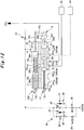
Fig. 10 illustrates a conventional emergency shut-off device, andFig. 11 and12 illustrate a trip system including the conventional emergency shut-off device. Note thatFig. 11 illustrates a state in normal operation (during operation of a steam turbine), andFig. 12 illustrates a state at the time of tripping. The trip system illustrated inFigs. 11 and12 supplies and drains control oil to and from aTTV 31 and a governor valve (hereinafter called the GV) 32 of the steam turbine (not illustrated), using an emergency shut-offdevice 10B. - The emergency shut-off
device 10B includes atrip piston 12 and atrip pilot valve 17 disposed in parallel with each other inside acylinder 11. Anend rod 13b on one end side (the left side in the figure) of arod 13a of thetrip piston 12 passes through thecylinder 11 and is exposed to the outside. Provided at the end of theend rod 13b is atrip button 13c. Provided on the other end side (the right side in the figure) of therod 13a is apiston valve 14, from which anend rod 13d extends. Theend rod 13d passes through thecylinder 11 and is exposed to the outside. The end of theend rod 13d is in contact with alever portion 16a of acam 16. In addition, therod 13a is provided with aspring 15 which applies a biasing force to therod 13a in the direction toward thecam 16. - An
end rod 18b on one end side (the left side in the figure) of arod 18a of thetrip pilot valve 17 also passes through thecylinder 11 and is exposed to the outside. Provided at the end of theend rod 18b is areset button 18c. Therod 18a is provided withmultiple piston valves 19 to 21 spaced at predetermined intervals. Anend rod 18d on the other side (the right side in the figure) of therod 18a also extends from thepiston valve 21, passes through thecylinder 11, and is exposed to the outside. The end of theend rod 18d is in contact with alatch portion 16b of thecam 16. In addition, theend rod 18b is provided with aspring 22 which applies a biasing force to theend rod 18b in the direction toward thecam 16. - The
cylinder 11 has aport 23 on thetrip piston 12 side, and thepiston valve 14 forms achamber 24. Thecylinder 11 also hasports 25a to 25f on thetrip pilot valve 17 side. Thepiston valve 19 forms achamber 26a, thepiston valve 19 and thepiston valve 20 form achamber 26b, thepiston valve 20 and thepiston valve 21 form achamber 26c, and thepiston valve 21 forms achamber 26d. - On the
trip piston 12 side, the control oil is supplied to and drained from thechamber 24 via theport 23. On thetrip pilot valve 17 side, air is discharged or the control oil is drained from the inside of thechamber 26a via theport 25a, air is discharged or the control oil is drained from thechamber 26a or thechamber 26b via theport 25b, the control oil is supplied to and drained from thechamber 26b (supplied to and drained from the GV 32) via theport 25c, the control oil is supplied to thechamber 26b or thechamber 26c via theport 25d, the control oil is supplied to and drained from thechamber 26c (supplied to and drained from the TTV 31) via theport 25e, and air is discharged or the control oil is drained from thechamber 26c or thechamber 26d via theport 25f. - A pipe for supplying the control oil from the supply source of the control oil is connected to the
port 25d and also connected to theport 23 via anorifice 34. A pipe for supplying and draining the control oil to and from theGV 32 is connected to theport 25c, and a pipe for supplying and draining the control oil to and from the TTV 31 is connected to theport 25e. - In addition, the
port 23 is connected to adrain device 35. Thisdrain device 35 includes two drainage lines having the same configuration and connected in parallel (duplex). Each drainage line includes avalve 36, avalve 37 andorifice 38 connected in parallel with thevalve 36, and asolenoid valve 39 connected downstream (on the draining side) of thevalve 36,valve 37, andorifice 38. - In the trip system described above, in normal operation, the
solenoid valves 39 are closed, and thus, the control oil is supplied to theport 23 via theorifice 34 and also supplied to theport 25d, as illustrated inFig. 11 . Note that inFig. 11 , solid line arrows indicate pipes under hydraulic pressure, and broken line arrows indicate pipes without hydraulic pressure. - Thus, in normal operation, the
chamber 24 is under hydraulic pressure via theorifice 34, and the hydraulic pressure of thechamber 24 opposes the biasing force of thespring 15, which prevents thetrip piston 12 from moving toward thecam 16. Accordingly, thelatch portion 16b of thecam 16 also prevents thetrip pilot valve 17 from moving toward thecam 16. - In such normal operation, the control oil supplied to the
port 25d is then supplied to the TTV 31 via thechamber 26c and theport 25e. In addition, the control oil from the GV 32 is drained via theport 25c, thechamber 26b, and theport 25b. - On the other hand, at the time of tripping, the
solenoid valves 39 are open, and the control oil is not supplied to the port 23 (no hydraulic pressure in the chamber 24), but supplied only to theport 25d, as illustrated inFig. 12 . Note that also inFig. 12 , solid line arrows indicate pipes under hydraulic pressure, and broken line arrows indicate pipes without hydraulic pressure. - At the time of tripping, since the
solenoid valves 39 are open, and no hydraulic pressure is applied to thechamber 24, the biasing force of thespring 15 moves thetrip piston 12 toward thecam 16. Accordingly, the end of theend rod 13d pushes thelever portion 16a, turning thecam 16, and the end of theend rod 18d comes off thelatch portion 16b. As a result, the biasing force of thespring 22 moves thetrip pilot valve 17 toward thecam 16. - Note that in the case where the
solenoid valves 39 do not open, pushing thetrip button 13c can cause the end of theend rod 13d to push thelever portion 16a to turn thecam 16, which in turn causes the end of theend rod 18d to come off thelatch portion 16b. As a result, it is possible to move thetrip pilot valve 17 toward thecam 16. - At the time of tripping described above, the control oil supplied to the
port 25d is then suppled to the GV 32 via thechamber 26b and theport 25c. The control oil from the TTV 31 is drained via theport 25e, thechamber 26c, and theport 25f. - In the emergency shut-off
device 10B of the trip system described above, the control oil and thesprings trip piston 12 and thetrip pilot valve 17. However, in the case where stagnation and deterioration of the control oil used cause sludge, the sludge may clog the sliding surfaces (portions indicated with symbols A inFig. 10 ) of thepiston valves trip piston 12 and thetrip pilot valve 17 to adhere to thecylinder 11, preventing them from moving. - The present invention has been made in view of the above problem, and an object thereof is to provide an emergency shut-off device capable of preventing the occurrence of sludge to achieve reliable operation.
- To solve the above problem, an emergency shut-off device according to a first aspect of the invention is
an emergency shut-off device, which shuts off supply of control oil to a trip-and-throttle valve of a steam turbine and closes the trip-and-throttle valve in an emergency, the emergency shut-off device comprising:
a cylinder; a piston which slides in the cylinder; a spring which applies a biasing force to the piston; a plurality of piston valves disposed on the piston; and a plurality of chambers which are formed by the piston valves, and which the control oil is supplied to and drained from, wherein
a sliding surface of each of the piston valves has a groove to leak the control oil in the chambers. - To solve the above problem, an emergency shut-off device according to a second aspect of the invention is
the emergency shut-off device according to the first aspect of the invention, wherein
the groove is a spiral groove formed on the sliding surface of each of the piston valves. - To solve the above problem, an emergency shut-off device according to a third aspect of the invention is
the emergency shut-off device according to the first aspect of the invention, wherein
the groove is a linear groove formed on the sliding surface of each of the piston valves and extending along an axis direction of the piston. - To solve the above problem, an emergency shut-off device according to a fourth aspect of the invention is
the emergency shut-off device according to any one of the first to third aspects of the invention, wherein
a depth of the groove is 1.0 mm or less. - To solve the above problem, an emergency shut-off device according to a fifth aspect of the invention is
the emergency shut-off device according to any one of the first to fourth aspects of the invention, wherein
the piston includes
a first piston and
a second piston which, when the first piston moves from a position in normal operation to a position in the emergency, moves from a position in the normal operation to a position in the emergency in an interlocked fashion, and
the chambers include at least
a movement chamber which is formed by the piston valve of the first piston and drains the control oil in the emergency to move the first piston from the position in the normal operation to the position in the emergency and
a trip-and-throttle valve chamber which is formed by the piston valve of the second piston, supplies the control oil to the trip-and-throttle valve when the second piston is at the position in the normal operation, and drains the control oil from the trip-and-throttle valve when the second piston is at the position in the emergency. - The present invention prevents the occurrence of sludge to achieve reliable operation, and thus improves the reliability of the trip operation of the trip-and-throttle valve.
-
- [
Fig. 1] Fig. 1 is a schematic diagram illustrating a trip system for a steam turbine having an emergency shut-off device according to the present invention, with the trip system in normal operation. - [
Fig. 2] Fig. 2 is a diagram for explaining an example of a piston valve of a trip piston in the emergency shut-off device illustrated inFig. 1 . - [
Fig. 3] Fig. 3 is a diagram for explaining an example of a piston valve of a trip pilot valve in the emergency shut-off device illustrated inFig. 1 . - [
Fig. 4] Fig. 4 is an enlarged view of the piston valve illustrated inFig. 2 . - [
Fig. 5] Fig. 5 is a graph for comparing the amount of leakage of control oil in a trip system of a steam turbine. - [
Fig. 6] Fig. 6 is a graph for comparing the amount of pressure loss of the control oil at a pipe in a drain device in the trip system of the steam turbine. - [
Fig. 7] Fig. 7 is a graph for comparing the amount of pressure loss of the control oil at a pipe for a trip-and-throttle valve in the trip system of the steam turbine. - [
Fig. 8A] Fig. 8A is a diagram for explaining a modification of the piston valve of the trip piston illustrated inFig. 2 . - [
Fig. 8B] Fig. 8B is a diagram for explaining a modification of the piston valve of the trip piston illustrated inFig. 2 . - [
Fig. 9A] Fig. 9A is a diagram for explaining a modification of the piston valve of the trip pilot valve illustrated inFig. 3 . - [
Fig. 9B] Fig. 9B is a diagram for explaining a modification of the piston valve of the trip pilot valve illustrated inFig. 3 . - [
Fig. 10] Fig. 10 is a schematic diagram illustrating a conventional emergency shut-off device. - [
Fig. 11] Fig. 11 is a schematic diagram illustrating a trip system of a steam turbine having the conventional emergency shut-off device illustrated inFig. 10 , with the trip system in normal operation. - [
Fig. 12] Fig. 12 is a schematic diagram illustrating the trip system of the steam turbine illustrated inFig. 11 at the time of tripping. - Hereinafter, an embodiment of an emergency shut-off device according to the present invention will be described. with reference to
Figs. 1 to 9B . Note that although here the TTV and the GV of a steam turbine are described as examples of control targets of the emergency shut-off device, the extraction control valve (ECV) may be further added as a control target. - A trip system having an emergency shut-off device according to this example is illustrated in
Fig. 1 . The emergency shut-offdevice 10A according to this example basically has substantially the same configuration as that of the conventional emergency shut-offdevice 10B illustrated inFigs. 10 to 12 , and a trip system having the emergency shut-offdevice 10A also has almost the same configuration as that of the conventional emergency shut-offdevice 10B. Thus, here the same constitutes are denoted by the same symbols, and repetitive descriptions thereof are omitted. - The trip system illustrated in
Fig. 1 supplies and drains control oil to and from aTTV 31 and aGV 32 of a steam turbine (not illustrated) using the emergency shut-offdevice 10A according to this example, and shuts off the supply of the control oil to close theTTV 31 in an emergency (trip operation) . Note that althoughFig. 1 illustrates the trip system during the normal operation (during the operation of the steam turbine), this trip system gets into the same state as that of the trip system illustrated inFig. 12 at the time of tripping. - Note that the emergency shut-off
device 10A according to this example includes as constituents acylinder 11; a trip piston 12 (first piston) and a trip pilot valve 17 (second piston) which are pistons sliding in thecylinder 11;springs trip piston 12 and thetrip pilot valve 17;piston valves trip piston 12 and thetrip pilot valve 17; andchambers piston valves - When the
trip piston 12 moves from a position in normal operation to a position in an emergency, acam 16 turns, which disengages the end of anend rod 18d from alatch portion 16b. As a result, the biasing force of thespring 22 moves thetrip pilot valve 17 from a position in normal operation to a position in an emergency in an interlocked fashion. - The chamber 24 (movement chamber) is formed by the
piston valve 14 of thetrip piston 12. When the control oil is drained from aport 23 in an emergency, the biasing force of thespring 15 moves thetrip piston 12 from the position in normal operation to the position in an emergency. - The
chamber 26b (governor valve chamber) is formed by thepiston valve 19 and thepiston valve 20 of thetrip pilot valve 17. When thetrip pilot valve 17 is at the position in normal operation, thechamber 26b connects aport 25b and aport 25c to each other to drain the control oil from theGV 32. When thetrip pilot valve 17 is at the position in an emergency, thechamber 26b connects theport 25c and aport 25d to each other to supply the control oil to the GV 32 (seeFig. 12 ). - The
chamber 26c (trip-and-throttle valve chamber) is formed by thepiston valve 20 and thepiston valve 21 of thetrip pilot valve 17. When thetrip pilot valve 17 is at the position in normal operation, thechamber 26c connects theport 25d and aport 25e to supply the control oil to theTTV 31. When thetrip pilot valve 17 is at the position in an emergency, thechamber 26c connects theport 25e and aport 25f to each other to drain the control oil from the TTV 31 (seeFig. 12 ). Note that thechambers trip pilot valve 17. - The control oil used in the emergency shut-off
device 10A of such a trip system may stagnate or deteriorate, and cause sludge, which clogs the sliding surfaces of thepiston valves trip piston 12 and thetrip pilot valve 17 and causes them to adhere to thecylinder 11, resulting in malfunctioning. - For this reason, in the emergency shut-off
device 10A according to this example, as also illustrated inFigs. 2 to 4 , each of thepiston valves spiral groove 51 formed on the sliding surface thereof as if thespiral groove 51 is wound around the sliding surface. Note thatFig. 4 is an enlarged view of a portion of the sliding surface of thepiston valve 14 illustrated inFig 2 . Thisspiral groove 51 is used to intentionally keep leaking a small amount of the control oil to prevent the control oil from stagnating or deteriorating, and thus preventing the occurrence of sludge. - Graphs illustrated in
Figs. 5 to 7 show the comparison between the result of a test performed with a trip system having the conventional emergency shut-offdevice 10B and the result of a test performed with a trip system having the emergency shut-offdevice 10A according to this example. - The data indicated by "Original" in
Figs. 5 to 7 are the results of the test performed with the trip system having the conventional emergency shut-offdevice 10B. In the conventional emergency shut-offdevice 10B, the sliding surface of each of thepiston valves device 10A according to this example. Referring toFig. 4 , in the test conditions, the pitch of thespiral groove 51 in all specimens is 3 mm, and the radius R indicating the depth of thespiral groove 51 in the specimen "R0.6" is R = 0. 6mm; in the specimen "R0.8", R = 0.8 mm; and in the specimen "R1.0", R = 1.0 mm. - In addition, in the test conditions, the temperatures T of the control oil supplied were of two kinds: T = 47 to 49°C (temperature in the normal supply range) and T = about 60°C (temperature of use limit), and the pressures P0 of the control oil supplied were of two kinds: P0 = 9 kgf/cm2 and P0 = 14 kgf/cm2. Combining these conditions, the test was performed in four conditions in total. Note that the pressure P0 is the pressure at a
pressure gauge 41 illustrated inFig. 1 . - Then, measured as test items were the amount of oil leakage (
Fig. 5 ) and the amount of pressure loss (Figs. 6 and7 ). Here,Fig. 6 indicates P1/PO × 100 as the amount of decrease in the pressure P1 based on the above P0 and the pressure P1 measured withpressure gauges 42 illustrated inFig. 1 , andFig. 7 indicates P2/P0 × 100 as the amount of decrease in the pressure P2 based on the above P0 and the pressure P2 measured with apressure gauge 43 illustrated inFig. 1 . Note that as illustrated inFig. 1 , the pressure gauges 42 are disposed on pipes in a drain device 35 (each between avalve 36 andorifice 38 and a solenoid valve 39), and thepressure gauge 43 is disposed on a pipe between the emergency shut-offdevice 10A and theTTV 31. - As illustrated in the graph of
Fig. 5 , the deeper the groove is (the larger the radius R is), the larger the leakage amount of the control oil is. In the case of "R1.0" (the groove depth is 1.0 mm), the leakage amount of the control oil is about three times that of "Original" (no groove). - On the other hand, as illustrated in the graphs of
Figs. 6 and7 , even though the oil leakage amount increases, the pressure loss amount of the control oil does not decrease largely. The amounts of decreases in the pressures P1 and P2 was 1% or less of the pressure P0 in any condition. - As described above, if the depth R of the
spiral groove 51 is about 1.0 mm or less, the pressure loss between before and after the emergency shut-offdevice 10A can be suppressed to be smaller than or equal to 1%. In other words, the depth R of thespiral groove 51 only needs to be 1.0 mm or less. - Note that as illustrated in
Figs. 8A and 8B , instead of thespiral groove 51 illustrated inFigs. 2 and 3 , multiplelinear grooves 52 extending along the axis direction of therod 13a may be formed on the sliding surface of thepiston valve 14, and as illustrated inFigs. 9A and 9B , multiplelinear grooves 52 extending along the axis direction of therod 18a may be formed on the sliding surface of each of thepiston valves 19 to 21. Here, as an example, on the sliding surface of each of thepiston valves linear grooves 52 at intervals of 90°. Thelinear grooves 52 illustrated inFigs. 8A, 8B ,9A and 9B also provide the same effects as those of thespiral groove 51 illustrated inFigs. 2 and 3 . - In addition, all the
piston valves spiral groove 51 and thelinear grooves 52 may be combined such that some piston valves have thespiral groove 51, and the other piston valves have the linear grooves. Further, thespiral grooves 51 and theliner grooves 52 may have different depths within the range of 1.0 mm or less. - The present invention is suitable to steam turbines for driving compressors or the like.
-
- 10A
- emergency shut-off device
- 12
- trip piston
- 14
- piston valve
- 15
- spring
- 17
- trip pilot valve
- 19, 20, 21
- piston valve
- 22
- spring
- 31
- TTV
- 51
- spiral groove
- 52
- linear groove
Claims (5)
- An emergency shut-off device which shuts off supply of control oil to a trip-and-throttle valve of a steam turbine and closes the trip-and-throttle valve in an emergency, the emergency shut-off device comprising:a cylinder;a piston which slides in the cylinder;a spring which applies a biasing force to the piston;a plurality of piston valves disposed on the piston; anda plurality of chambers which are formed by the piston valves, and which the control oil is supplied to and drained from, whereina sliding surface of each of the piston valves has a groove to leak the control oil in the chambers.
- The emergency shut-off device according to claim 1, wherein
the groove is a spiral groove formed on the sliding surface of each of the piston valves. - The emergency shut-off device according to claim 1, wherein
the groove is a linear groove formed on the sliding surface of each of the piston valves and extending along an axis direction of the piston. - The emergency shut-off device according to any one of claims 1 to 3, wherein
a depth of the groove is 1.0 mm or less. - The emergency shut-off device according to any one of claims 1 to 4, wherein
the piston includes
a first piston and
a second piston which, when the first piston moves from a position in normal operation to a position in the emergency, moves from a position in the normal operation to a position in the emergency in an interlocked fashion, and
the chambers include at least
a movement chamber which is formed by the piston valve of the first piston, and drains the control oil in the emergency to move the first piston from the position in the normal operation to the position in the emergency and
a trip-and-throttle valve chamber which is formed by the piston valve of the second piston, supplies the control oil to the trip-and-throttle valve when the second piston is at the position in the normal operation, and drains the control oil from the trip-and-throttle valve when the second piston is at the position in the emergency.
Applications Claiming Priority (1)
| Application Number | Priority Date | Filing Date | Title |
|---|---|---|---|
| PCT/JP2015/085308 WO2017104037A1 (en) | 2015-12-17 | 2015-12-17 | Emergency shut-off device |
Publications (2)
| Publication Number | Publication Date |
|---|---|
| EP3351745A1 true EP3351745A1 (en) | 2018-07-25 |
| EP3351745A4 EP3351745A4 (en) | 2018-12-05 |
Family
ID=59056222
Family Applications (1)
| Application Number | Title | Priority Date | Filing Date |
|---|---|---|---|
| EP15910727.5A Withdrawn EP3351745A4 (en) | 2015-12-17 | 2015-12-17 | Emergency shut-off device |
Country Status (4)
| Country | Link |
|---|---|
| US (1) | US11352899B2 (en) |
| EP (1) | EP3351745A4 (en) |
| JP (1) | JP6743049B2 (en) |
| WO (1) | WO2017104037A1 (en) |
Families Citing this family (1)
| Publication number | Priority date | Publication date | Assignee | Title |
|---|---|---|---|---|
| JP7814279B2 (en) | 2022-09-29 | 2026-02-16 | 三菱重工コンプレッサ株式会社 | Valve device |
Family Cites Families (45)
| Publication number | Priority date | Publication date | Assignee | Title |
|---|---|---|---|---|
| US525462A (en) * | 1894-09-04 | Samuel o | ||
| US2402729A (en) * | 1944-12-20 | 1946-06-25 | J D Buchanan | Variable restrictor |
| US2739607A (en) * | 1952-05-03 | 1956-03-27 | Gen Electric | Fluid pressure regulating device |
| DE1074346B (en) * | 1955-02-21 | 1960-01-28 | Bendix Aviation Corporation, New York, N. Y. (V. St. A.) | Piston valve |
| US3018041A (en) * | 1957-05-24 | 1962-01-23 | Gen Motors Corp | Hydraulic function generator |
| DE1147450B (en) * | 1962-03-23 | 1963-04-18 | Arap Armaturen Und App Ges Mit | Multi-stage throttle valve with a valve spindle having throttle channels |
| US3460577A (en) * | 1966-06-24 | 1969-08-12 | Sperry Rand Corp | Spool type valve |
| US3456688A (en) * | 1967-10-16 | 1969-07-22 | Racine Hydraulics Inc | Valve having cushioning means |
| US3812883A (en) * | 1968-12-28 | 1974-05-28 | Sumitomo Precision Prod Co | Mechanism for preventing the sticking of spool valves |
| US3677362A (en) * | 1970-09-02 | 1972-07-18 | Int Harvester Co | Hydrostatic transmission hydraulic control and single lever for operating same |
| US3722367A (en) * | 1970-11-04 | 1973-03-27 | Applied Power Ind Inc | Steering system |
| DE2161794C3 (en) * | 1970-12-14 | 1975-06-05 | International Harvester Co., Chicago, Ill. (V.St.A.) | Pressure control device for hydraulic systems |
| US3875849A (en) * | 1972-09-11 | 1975-04-08 | Applied Power Inc | Electro-hydraulic proportional servo actuator |
| US4069843A (en) * | 1973-04-02 | 1978-01-24 | International Harvester Company | Clutch cylinder circuit and charging valve therefor |
| US3840050A (en) * | 1973-04-26 | 1974-10-08 | Gen Electric | High-pressure trip valve |
| GB1484005A (en) * | 1974-08-16 | 1977-08-24 | Lucas Industries Ltd | Land vehicle wheel suspension arrangement |
| US4122868A (en) * | 1975-01-24 | 1978-10-31 | International Harvester Company | Hydraulic valve assembly having an axial flow force balanced spool |
| US4407328A (en) * | 1975-03-24 | 1983-10-04 | Dresser Industries, Inc. | Clutch-brake steering mechanism for tractors |
| US4308893A (en) * | 1975-03-24 | 1982-01-05 | International Harvester Company | Clutch-brake steering valve mechanism for tractors |
| US4099588A (en) * | 1976-09-01 | 1978-07-11 | Caterpillar Tractor Co. | Responsive pilot-operated control valve for front wheel drive |
| US4319608A (en) * | 1977-05-02 | 1982-03-16 | Raikov Ivan Y | Liquid flow splitter |
| US4245816A (en) * | 1978-04-19 | 1981-01-20 | Caterpillar Tractor Co. | Flow force balanced spool valve |
| US4476748A (en) * | 1981-12-16 | 1984-10-16 | Eaton Corporation | Preselect shift control |
| JPS60147703U (en) * | 1984-03-14 | 1985-10-01 | 株式会社日立製作所 | emergency shutoff device |
| USRE33053E (en) * | 1984-05-07 | 1989-09-12 | Cameron Iron Works Usa Inc. | Low noise valve |
| JPH0240140B2 (en) * | 1984-10-30 | 1990-09-10 | Nissan Motor | MUDANHENSOKUKINOHENSOKUSEIGYOBEN |
| JPS6321703U (en) * | 1986-07-25 | 1988-02-13 | ||
| JPS6336768U (en) | 1986-08-27 | 1988-03-09 | ||
| JPH0788741B2 (en) | 1987-02-23 | 1995-09-27 | 石油公団 | Fuel control shutoff valve for mine bottom boiler |
| JPH0351284U (en) * | 1989-09-26 | 1991-05-17 | ||
| US4941508A (en) * | 1989-12-28 | 1990-07-17 | Dana Corporation | Force balanced hydraulic spool valve |
| JPH0564401U (en) | 1992-02-06 | 1993-08-27 | 三菱重工業株式会社 | Stop valve test equipment |
| US5193584A (en) * | 1992-02-20 | 1993-03-16 | Sauer Inc. | Spool valve and method of making the same |
| JPH06101413A (en) * | 1992-09-18 | 1994-04-12 | Toshiba Corp | On-off valve abnormality monitoring device |
| JPH09119530A (en) * | 1995-10-26 | 1997-05-06 | Mitsubishi Heavy Ind Ltd | Emergency shutting off device |
| JP2986148B2 (en) * | 1996-10-29 | 1999-12-06 | 株式会社東芝 | Turbine emergency equipment |
| US6460561B1 (en) * | 1998-10-28 | 2002-10-08 | Luk Getriebe-Systeme Gmbh | Valve piston and valve equipped with same |
| JP3777273B2 (en) * | 1999-08-17 | 2006-05-24 | 株式会社東芝 | Emergency control device |
| JP2001241559A (en) * | 2000-03-01 | 2001-09-07 | Aichi Corp | Spool valve |
| GB2366352A (en) * | 2000-08-22 | 2002-03-06 | Imi Cornelius | Valve |
| FR2814215B1 (en) * | 2000-09-18 | 2003-06-27 | Snecma Moteurs | SELF-CLEANING DOSING DEVICE |
| US6450194B1 (en) * | 2000-09-26 | 2002-09-17 | Case Corporation | Spool notch geometry for hydraulic spool valve |
| US20120175540A1 (en) * | 2009-09-28 | 2012-07-12 | Hirofumi Hase | Hydraulic pressure controlling solenoid valve |
| KR100995305B1 (en) * | 2010-06-21 | 2010-11-19 | 주식회사 에네스코 | Turbine Front Standard Mechanical Trip Valve |
| DE112016000086B4 (en) * | 2016-05-31 | 2018-12-27 | Komatsu Ltd. | SHIFT VALVE AND WORK VEHICLE |
-
2015
- 2015-12-17 US US15/769,041 patent/US11352899B2/en active Active
- 2015-12-17 EP EP15910727.5A patent/EP3351745A4/en not_active Withdrawn
- 2015-12-17 WO PCT/JP2015/085308 patent/WO2017104037A1/en not_active Ceased
- 2015-12-17 JP JP2017555939A patent/JP6743049B2/en not_active Expired - Fee Related
Also Published As
| Publication number | Publication date |
|---|---|
| WO2017104037A1 (en) | 2017-06-22 |
| EP3351745A4 (en) | 2018-12-05 |
| US11352899B2 (en) | 2022-06-07 |
| JP6743049B2 (en) | 2020-08-19 |
| US20200240284A1 (en) | 2020-07-30 |
| JPWO2017104037A1 (en) | 2018-08-09 |
Similar Documents
| Publication | Publication Date | Title |
|---|---|---|
| US9383024B2 (en) | Valve | |
| US9651067B2 (en) | Hydraulic system with a dynamic seal | |
| CN105698880A (en) | Multi-Double Block and Bleed System for an Orifice Fitting | |
| US9394928B2 (en) | Dynamic seal wear mitigation system | |
| KR102775328B1 (en) | Pipe damage detecting system and method for detecting pipe damage using the same | |
| US20070095401A1 (en) | Device, Method and Apparatus | |
| US11352899B2 (en) | Emergency shut-off device | |
| EP3894757B1 (en) | Distribution pump arrangement for a hydraulic distribution system having changing flowing direction | |
| US8511330B1 (en) | Servo minimum pressure valve | |
| CN106461113A (en) | High integrity pressure protecting system (HIPPS) for a fluid line | |
| CN103038449B (en) | Control device and method for an combined bracket in the work face of a mine | |
| JP6577314B2 (en) | Steam turbine valve drive device and steam turbine valve | |
| US20130099147A1 (en) | Valve device with a valve housing having multiple shift tongues | |
| US20130180614A1 (en) | Double isolation for double chamber differential pressure meter | |
| US20160108777A1 (en) | Gas exchange valve actuator for axial displacement of a gas exchange valve of a combustion engine | |
| US10550719B2 (en) | Trip system for steam turbine | |
| US1941357A (en) | Fluid control system | |
| RU2527276C1 (en) | Pressure control valve | |
| US9574682B2 (en) | Method of determining an operating state of a transmission latching valve | |
| US8950420B2 (en) | Containment housing for a fuel control housing | |
| CN102352823A (en) | Oil brake system used for locking position of engine room of wind turbine | |
| Mikhailov et al. | Optimization of the Steam Turbine Protection System as Part of an Electrohydraulic Control System | |
| KR20180031919A (en) | An operating method of the smart valve that quickly detects rupture in a closed piping and can isolate it | |
| WO2017027001A1 (en) | Multi-seat valve | |
| Dziubak et al. | Selected problems in diagnostic testing of automatic transmissions (AT) |
Legal Events
| Date | Code | Title | Description |
|---|---|---|---|
| PUAI | Public reference made under article 153(3) epc to a published international application that has entered the european phase |
Free format text: ORIGINAL CODE: 0009012 |
|
| 17P | Request for examination filed |
Effective date: 20180416 |
|
| AK | Designated contracting states |
Kind code of ref document: A1 Designated state(s): AL AT BE BG CH CY CZ DE DK EE ES FI FR GB GR HR HU IE IS IT LI LT LU LV MC MK MT NL NO PL PT RO RS SE SI SK SM TR |
|
| AX | Request for extension of the european patent |
Extension state: BA ME |
|
| STAA | Information on the status of an ep patent application or granted ep patent |
Free format text: STATUS: THE APPLICATION HAS BEEN WITHDRAWN |
|
| RIC1 | Information provided on ipc code assigned before grant |
Ipc: F01D 21/18 20060101ALI20181018BHEP Ipc: F01D 21/00 20060101AFI20181018BHEP Ipc: F01D 21/16 20060101ALI20181018BHEP |
|
| A4 | Supplementary search report drawn up and despatched |
Effective date: 20181026 |
|
| 18W | Application withdrawn |
Effective date: 20181109 |