EP3351730A1 - Component and method for forming a component - Google Patents
Component and method for forming a component Download PDFInfo
- Publication number
- EP3351730A1 EP3351730A1 EP18151936.4A EP18151936A EP3351730A1 EP 3351730 A1 EP3351730 A1 EP 3351730A1 EP 18151936 A EP18151936 A EP 18151936A EP 3351730 A1 EP3351730 A1 EP 3351730A1
- Authority
- EP
- European Patent Office
- Prior art keywords
- component
- insert
- channel
- combinations
- superalloy
- Prior art date
- Legal status (The legal status is an assumption and is not a legal conclusion. Google has not performed a legal analysis and makes no representation as to the accuracy of the status listed.)
- Withdrawn
Links
Images




Classifications
-
- F—MECHANICAL ENGINEERING; LIGHTING; HEATING; WEAPONS; BLASTING
- F01—MACHINES OR ENGINES IN GENERAL; ENGINE PLANTS IN GENERAL; STEAM ENGINES
- F01D—NON-POSITIVE DISPLACEMENT MACHINES OR ENGINES, e.g. STEAM TURBINES
- F01D9/00—Stators
- F01D9/06—Fluid supply conduits to nozzles or the like
- F01D9/065—Fluid supply or removal conduits traversing the working fluid flow, e.g. for lubrication-, cooling-, or sealing fluids
-
- B—PERFORMING OPERATIONS; TRANSPORTING
- B22—CASTING; POWDER METALLURGY
- B22D—CASTING OF METALS; CASTING OF OTHER SUBSTANCES BY THE SAME PROCESSES OR DEVICES
- B22D17/00—Pressure die casting or injection die casting, i.e. casting in which the metal is forced into a mould under high pressure
-
- B—PERFORMING OPERATIONS; TRANSPORTING
- B22—CASTING; POWDER METALLURGY
- B22D—CASTING OF METALS; CASTING OF OTHER SUBSTANCES BY THE SAME PROCESSES OR DEVICES
- B22D19/00—Casting in, on, or around objects which form part of the product
- B22D19/0072—Casting in, on, or around objects which form part of the product for making objects with integrated channels
-
- B—PERFORMING OPERATIONS; TRANSPORTING
- B22—CASTING; POWDER METALLURGY
- B22D—CASTING OF METALS; CASTING OF OTHER SUBSTANCES BY THE SAME PROCESSES OR DEVICES
- B22D21/00—Casting non-ferrous metals or metallic compounds so far as their metallurgical properties are of importance for the casting procedure; Selection of compositions therefor
- B22D21/002—Castings of light metals
- B22D21/005—Castings of light metals with high melting point, e.g. Be 1280 degrees C, Ti 1725 degrees C
-
- B—PERFORMING OPERATIONS; TRANSPORTING
- B23—MACHINE TOOLS; METAL-WORKING NOT OTHERWISE PROVIDED FOR
- B23K—SOLDERING OR UNSOLDERING; WELDING; CLADDING OR PLATING BY SOLDERING OR WELDING; CUTTING BY APPLYING HEAT LOCALLY, e.g. FLAME CUTTING; WORKING BY LASER BEAM
- B23K1/00—Soldering, e.g. brazing, or unsoldering
- B23K1/0008—Soldering, e.g. brazing, or unsoldering specially adapted for particular articles or work
- B23K1/0018—Brazing of turbine parts
-
- B—PERFORMING OPERATIONS; TRANSPORTING
- B23—MACHINE TOOLS; METAL-WORKING NOT OTHERWISE PROVIDED FOR
- B23K—SOLDERING OR UNSOLDERING; WELDING; CLADDING OR PLATING BY SOLDERING OR WELDING; CUTTING BY APPLYING HEAT LOCALLY, e.g. FLAME CUTTING; WORKING BY LASER BEAM
- B23K31/00—Processes relevant to this subclass, specially adapted for particular articles or purposes, but not covered by any single one of main groups B23K1/00 - B23K28/00
- B23K31/02—Processes relevant to this subclass, specially adapted for particular articles or purposes, but not covered by any single one of main groups B23K1/00 - B23K28/00 relating to soldering or welding
-
- B—PERFORMING OPERATIONS; TRANSPORTING
- B23—MACHINE TOOLS; METAL-WORKING NOT OTHERWISE PROVIDED FOR
- B23P—METAL-WORKING NOT OTHERWISE PROVIDED FOR; COMBINED OPERATIONS; UNIVERSAL MACHINE TOOLS
- B23P15/00—Making specific metal objects by operations not covered by a single other subclass or a group in this subclass
- B23P15/02—Making specific metal objects by operations not covered by a single other subclass or a group in this subclass turbine or like blades from one piece
-
- B—PERFORMING OPERATIONS; TRANSPORTING
- B33—ADDITIVE MANUFACTURING TECHNOLOGY
- B33Y—ADDITIVE MANUFACTURING, i.e. MANUFACTURING OF THREE-DIMENSIONAL [3D] OBJECTS BY ADDITIVE DEPOSITION, ADDITIVE AGGLOMERATION OR ADDITIVE LAYERING, e.g. BY 3D PRINTING, STEREOLITHOGRAPHY OR SELECTIVE LASER SINTERING
- B33Y10/00—Processes of additive manufacturing
-
- B—PERFORMING OPERATIONS; TRANSPORTING
- B33—ADDITIVE MANUFACTURING TECHNOLOGY
- B33Y—ADDITIVE MANUFACTURING, i.e. MANUFACTURING OF THREE-DIMENSIONAL [3D] OBJECTS BY ADDITIVE DEPOSITION, ADDITIVE AGGLOMERATION OR ADDITIVE LAYERING, e.g. BY 3D PRINTING, STEREOLITHOGRAPHY OR SELECTIVE LASER SINTERING
- B33Y80/00—Products made by additive manufacturing
-
- F—MECHANICAL ENGINEERING; LIGHTING; HEATING; WEAPONS; BLASTING
- F01—MACHINES OR ENGINES IN GENERAL; ENGINE PLANTS IN GENERAL; STEAM ENGINES
- F01D—NON-POSITIVE DISPLACEMENT MACHINES OR ENGINES, e.g. STEAM TURBINES
- F01D25/00—Component parts, details, or accessories, not provided for in, or of interest apart from, other groups
- F01D25/005—Selecting particular materials
-
- F—MECHANICAL ENGINEERING; LIGHTING; HEATING; WEAPONS; BLASTING
- F01—MACHINES OR ENGINES IN GENERAL; ENGINE PLANTS IN GENERAL; STEAM ENGINES
- F01D—NON-POSITIVE DISPLACEMENT MACHINES OR ENGINES, e.g. STEAM TURBINES
- F01D5/00—Blades; Blade-carrying members; Heating, heat-insulating, cooling or antivibration means on the blades or the members
- F01D5/12—Blades
- F01D5/14—Form or construction
- F01D5/18—Hollow blades, i.e. blades with cooling or heating channels or cavities; Heating, heat-insulating or cooling means on blades
- F01D5/186—Film cooling
-
- F—MECHANICAL ENGINEERING; LIGHTING; HEATING; WEAPONS; BLASTING
- F01—MACHINES OR ENGINES IN GENERAL; ENGINE PLANTS IN GENERAL; STEAM ENGINES
- F01D—NON-POSITIVE DISPLACEMENT MACHINES OR ENGINES, e.g. STEAM TURBINES
- F01D5/00—Blades; Blade-carrying members; Heating, heat-insulating, cooling or antivibration means on the blades or the members
- F01D5/12—Blades
- F01D5/14—Form or construction
- F01D5/18—Hollow blades, i.e. blades with cooling or heating channels or cavities; Heating, heat-insulating or cooling means on blades
- F01D5/187—Convection cooling
- F01D5/188—Convection cooling with an insert in the blade cavity to guide the cooling fluid, e.g. forming a separation wall
-
- F—MECHANICAL ENGINEERING; LIGHTING; HEATING; WEAPONS; BLASTING
- F01—MACHINES OR ENGINES IN GENERAL; ENGINE PLANTS IN GENERAL; STEAM ENGINES
- F01D—NON-POSITIVE DISPLACEMENT MACHINES OR ENGINES, e.g. STEAM TURBINES
- F01D9/00—Stators
- F01D9/02—Nozzles; Nozzle boxes; Stator blades; Guide conduits, e.g. individual nozzles
-
- B—PERFORMING OPERATIONS; TRANSPORTING
- B23—MACHINE TOOLS; METAL-WORKING NOT OTHERWISE PROVIDED FOR
- B23K—SOLDERING OR UNSOLDERING; WELDING; CLADDING OR PLATING BY SOLDERING OR WELDING; CUTTING BY APPLYING HEAT LOCALLY, e.g. FLAME CUTTING; WORKING BY LASER BEAM
- B23K2101/00—Articles made by soldering, welding or cutting
- B23K2101/001—Turbines
-
- F—MECHANICAL ENGINEERING; LIGHTING; HEATING; WEAPONS; BLASTING
- F05—INDEXING SCHEMES RELATING TO ENGINES OR PUMPS IN VARIOUS SUBCLASSES OF CLASSES F01-F04
- F05D—INDEXING SCHEME FOR ASPECTS RELATING TO NON-POSITIVE-DISPLACEMENT MACHINES OR ENGINES, GAS-TURBINES OR JET-PROPULSION PLANTS
- F05D2220/00—Application
- F05D2220/30—Application in turbines
- F05D2220/32—Application in turbines in gas turbines
-
- F—MECHANICAL ENGINEERING; LIGHTING; HEATING; WEAPONS; BLASTING
- F05—INDEXING SCHEMES RELATING TO ENGINES OR PUMPS IN VARIOUS SUBCLASSES OF CLASSES F01-F04
- F05D—INDEXING SCHEME FOR ASPECTS RELATING TO NON-POSITIVE-DISPLACEMENT MACHINES OR ENGINES, GAS-TURBINES OR JET-PROPULSION PLANTS
- F05D2230/00—Manufacture
- F05D2230/20—Manufacture essentially without removing material
- F05D2230/23—Manufacture essentially without removing material by permanently joining parts together
- F05D2230/232—Manufacture essentially without removing material by permanently joining parts together by welding
-
- F—MECHANICAL ENGINEERING; LIGHTING; HEATING; WEAPONS; BLASTING
- F05—INDEXING SCHEMES RELATING TO ENGINES OR PUMPS IN VARIOUS SUBCLASSES OF CLASSES F01-F04
- F05D—INDEXING SCHEME FOR ASPECTS RELATING TO NON-POSITIVE-DISPLACEMENT MACHINES OR ENGINES, GAS-TURBINES OR JET-PROPULSION PLANTS
- F05D2230/00—Manufacture
- F05D2230/20—Manufacture essentially without removing material
- F05D2230/23—Manufacture essentially without removing material by permanently joining parts together
- F05D2230/232—Manufacture essentially without removing material by permanently joining parts together by welding
- F05D2230/237—Brazing
Definitions
- the present invention is generally directed to a cooling component and method of forming a cooling component. More specifically, the present invention is directed to a cooling component including a channel and an insert, and a method of forming a cooling component.
- Turbine vane and blade cooling arts disclose various configurations for enhancing film cooling effectiveness and reducing the required amount of cooling air in order to increase the overall efficiency of the engine while obtaining a suitable useful life for the vanes and blades.
- typical vane and blade airfoils in the high pressure turbine section of the engine include cooling holes that extend through the pressure side, or suction side, or both, for discharging a film of cooling air along the outer surface of the airfoil to effect film cooling in a conventional manner.
- Film cooling effectiveness depends on many factors. One such factor is the length of the hole. Film cooling effectiveness is proportional to the length of the hole. However, reduced wall thickness designed to increase the effectiveness of both convective cooling and film cooling, may present a challenge since it limits the length of hole.
- a component including a channel and an insert is provided.
- the channel is configured to extend through a wall thickness of the component from an inner surface of the component to an outer surface of the component and is defined by an inner channel surface.
- the insert is configured to permit flow of cooling fluid and has an outer insert surface corresponding to and attached to the inner channel surface.
- a turbine component including a channel and an insert.
- the channel is configured to extend through a wall thickness of the component from an inner surface of the component to an outer surface of the component and is defined by an inner channel surface.
- the insert is configured to permit flow of cooling fluid and has an outer insert surface corresponding to and attached to the inner channel surface.
- the insert has a protruded portion protruding from the inner surface of the turbine component.
- a method for forming a component includes a step of forming a channel configured to extend through a wall thickness of the component from an inner surface of the component to an outer surface of the component.
- the channel is defined by an inner channel surface.
- the method further includes a step of forming an insert.
- the method further includes a step of attaching the insert onto the inner channel surface.
- the insert is configured to permit flow of cooling fluid.
- Embodiments of the present disclosure in comparison to components and method not utilizing one or more features disclosed herein, enable use of less cooling air, reduce component weight, reduce low cycle fatigue, and improve component life cycle.
- At least one means one or more and thus includes individual components as well as mixtures/combinations.
- the present invention may comprise a component including a channel and an insert.
- the component herein illustrated may comprise a metal or an alloy.
- the alloy may comprise an HTW alloy.
- HTW alloy is an alloy that exhibits liquation, hot and strain-age cracking, and which is therefore impractical to weld.
- the HTW alloy is a superalloy.
- superalloy is used herein as it is commonly used in the art; i.e., a highly corrosion and oxidation resistant alloy that exhibits excellent mechanical strength and resistance to creep at high temperatures.
- the superalloy may include nickel-based superalloy, cobalt-based superalloy, iron-based superalloy, titanium-based superalloy, or combinations thereof.
- the superalloy may include, but not be limited to, a material selected from the group consisting of Hastelloy, Inconel alloys, Waspaloy, Rene alloys, such as GTD111, GTD222, GTD444, GTD262, Mar M247, IN100, IN 738, René 80, IN 939, René N2, René N4, René N5, René N6, René 65, René 77 (Udimet 700), René 80, René 88DT, René 104, René 108, René 125, René 142, René 195, René N500, René N515, IN 706, Nimonic 263, CM247, MarM247, CMSX-4, MGA1400, MGA2400, INCONEL 700, INCONEL 738, INCONEL
- ASTROLOY refers to an alloy including a composition, by weight, of about 15% chromium, about 17% cobalt, about 5.3% molybdenum, about 4% aluminum, about 3.5% titanium, and a balance of nickel.
- DS Siemet refers to an alloy including a composition, by weight, of about 9% cobalt, about 12.1% chromium, about 3.6% aluminum, about 4% titanium, about 5.2% tantalum, about 3.7% tungsten, about 1.8% molybdenum, and a balance of nickel.
- GTD111 refers to an alloy including a composition, by weight, of about 14% chromium, about 9.5% cobalt, about 3.8% tungsten, about 4.9% titanium, about 3% aluminum, about 0.1% iron, about 2.8% tantalum, about 1.6% molybdenum, about 0.1% carbon, and a balance of nickel.
- GTD262 refers to an alloy including a composition, by weight, of about 22.5% chromium, about 19% cobalt, about 2% tungsten, about 1.35% niobium, about 2.3% titanium, about 1.7% aluminum, about 0.1% carbon, and a balance of nickel.
- GTD444" refers to an alloy including a composition, by weight, of about 7.5% cobalt, about 0.2% iron, about 9.75% chromium, about 4.2% aluminum, about 3.5% titanium, about 4.8% tantalum, about 6% tungsten, about 1.5% molybdenum, about 0.5% niobium, about 0.2% silicon, about 0.15% hafnium, and a balance of nickel.
- MMA1400 refers to an alloy including a composition, by weight, of about 10% cobalt, about 14% chromium, about 4% aluminum, about 2.7% titanium, about 4.7% tantalum, about 4.3% tungsten, about 1.5% molybdenum, about 0.1% carbon, and a balance of nickel.
- MMA2400 refers to an alloy including a composition, by weight, of about 19% cobalt, about 19% chromium, about 1.9% aluminum, about 3.7% titanium, about 1.4% tantalum, about 6% tungsten, about 1% niobium, about 0.1% carbon, and a balance of nickel.
- PMA 1480 refers to an alloy including a composition, by weight, of about 10% chromium, about 5% cobalt, about 5% aluminum, about 1.5% titanium, about 12% tantalum, about 4% tungsten, and a balance of nickel.
- PWA1483 refers to an alloy including a composition, by weight, of about 9% cobalt, about 12.2% chromium, about 3.6% aluminum, about 4.1% titanium, about 5% tantalum, about 3.8% tungsten, about 1.9% molybdenum, and a balance of nickel.
- PMA 1484" refers to an alloy including a composition, by weight, of about 5% chromium, about 10% cobalt, about 2% molybdenum, about 5.6% aluminum, about 9% tantalum, about 6% tungsten, and a balance of nickel.
- Raé N2 refers to an alloy including a composition, by weight, of about 7.5% cobalt, about 13% chromium, about 6.6% aluminum, about 5% tantalum, about 3.8% tungsten, about 1.6% rhenium, about 0.15% hafnium, and a balance of nickel.
- René N4 refers to an alloy including a composition, by weight, of about 9.75% chromium, about 7.5% cobalt, about 4.2% aluminum, about 3.5% titanium, about 1.5% molybdenum, about 6.0% tungsten, about 4.8% tantalum, about 0.5% niobium, about 0.15% hafnium, and a balance of nickel.
- Raé N5 refers to an alloy including a composition, by weight, of about 7.5% cobalt, about 7.0% chromium, about 6.5% tantalum, about 6.2% aluminum, about 5.0% tungsten, about 3.0% rhenium, about 1.5% molybdenum, about 0.15% hafnium, and a balance of nickel.
- Raé N6 refers to an alloy including a composition, by weight, of about 12.5% cobalt, about 4.2% chromium, about 7.2% tantalum, about 5.75% aluminum, about 6% tungsten, about 5.4% rhenium, about 1.4% molybdenum, about 0.15% hafnium, and a balance of nickel.
- René 65 refers to an alloy including a composition, by weight, of about 13% cobalt, up to about 1.2% iron, about 16% chromium, about 2.1% aluminum, about 3.75% titanium, about 4% tungsten, about 4% molybdenum, about 0.7% niobium, up to about 0.15% manganese, and a balance of nickel.
- Rambo 77 (Udimet 700) refers to an alloy including a composition, by weight, of about 15% chromium, about 17% cobalt, about 5.3% molybdenum, about 3.35% titanium, about 4.2% aluminum, and a balance of nickel.
- Raster 80 refers to an alloy including a composition, by weight, of about 14% chromium, about 9.5% cobalt, about 4% molybdenum, about 3% aluminum, about 5% titanium, about 4% tungsten, about 0.17% carbon, and a balance of nickel.
- René 88DT refers to an alloy including a composition, by weight, of about 16% chromium, about 13% cobalt, about 4% molybdenum, about 0.7% niobium, about 2.1% aluminum, about 3.7% titanium, about 4% tungsten, about 0.1% rhenium, a maximum of about 4.3% rhenium and tungsten, and a balance of nickel.
- René 104" refers to an alloy including a composition, by weight, of about 13.1% chromium, about 18.2% cobalt, about 3.8% molybdenum, about 1.9% tungsten, about 1.4% niobium, about 3.5% aluminum, about 3.5% titanium, about 2.7% tantalum, and a balance of nickel.
- René 108 refers to an alloy including a composition, by weight, of about 8.4% chromium, about 9.5% cobalt, about 5.5% aluminum, about 0.7% titanium, about 9.5% tungsten, about 0.5% molybdenum, about 3% tantalum, about 1.5% hafnium, and a balance of nickel.
- René 125 refers to an alloy including a composition, by weight, of about 8.5% chromium, about 10% cobalt, about 4.8% aluminum, up to about 2.5% titanium, about 8% tungsten, up to about 2% molybdenum, about 3.8% tantalum, about 1.4% hafnium, about 0.11% carbon, and a balance of nickel.
- René 142 refers to an alloy including a composition, by weight, of about 6.8% chromium, about 12% cobalt, about 6.1% aluminum, about 4.9% tungsten, about 1.5% molybdenum, about 2.8% rhenium, about 6.4% tantalum, about 1.5% hafnium, and a balance of nickel.
- René 195" refers to an alloy including a composition, by weight, of about 7.6% chromium, about 3.1% cobalt, about 7.8% aluminum, about 5.5% tantalum, about 0.1% molybdenum, about 3.9% tungsten, about 1.7% rhenium, about 0.15% hafnium, and a balance of nickel.
- Raé N500 refers to an alloy including a composition, by weight, of about 7.5% cobalt, about 0.2% iron, about 6% chromium, about 6.25% aluminum, about 6.5% tantalum, about 6.25% tungsten, about 1.5% molybdenum, about 0.15% hafnium, and a balance of nickel.
- Raster N515" refers to an alloy including a composition, by weight, of about 7.5% cobalt, about 0.2% iron, about 6% chromium, about 6.25% aluminum, about 6.5% tantalum, about 6.25% tungsten, about 2% molybdenum, about 0.1% niobium, about 1.5% rhenium, about 0.6% hafnium, and a balance of nickel.
- MarM247 and CM247 refer to an alloy including a composition, by weight, of about 5.5% aluminum, about 0.15% carbon, about 8.25% chromium, about 10% cobalt, about 10% tungsten, about 0.7% molybdenum, about 0.5% iron, about 1% titanium, about 3% tantalum, about 1.5% hafnium, and a balance of nickel.
- I100 refers to an alloy including a composition, by weight, of about 10% chromium, about 15% cobalt, about 3% molybdenum, about 4.7% titanium, about 5.5% aluminum, about 0.18% carbon, and a balance of nickel.
- INCONEL 700 refers to an alloy including a composition, by weight, of up to about 0.12% carbon, about 15% chromium, about 28.5% cobalt, about 3.75% molybdenum, about 2.2% titanium, about 3% aluminum, about 0.7% iron, up to about 0.3% silicon, up to about 0.1% manganese, and a balance of nickel.
- INCONEL 738 refers to an alloy including a composition, by weight, of about 0.17% carbon, about 16% chromium, about 8.5% cobalt, about 1.75% molybdenum, about 2.6% tungsten, about 3.4% titanium, about 3.4% aluminum, about 0.1% zirconium, about 2% niobium, and a balance of nickel.
- INCONEL 792 refers to an alloy including a composition, by weight, of about 12.4% chromium, about 9% cobalt, about 1.9% molybdenum, about 3.8% tungsten, about 3.9% tantalum, about 3.1% aluminum, about 4.5% titanium, about 0.12% carbon, about 0.1% zirconium, and a balance of nickel.
- UIMET 500 refers to an alloy including a composition, by weight, of about 18.5% chromium, about 18.5% cobalt, about 4% molybdenum, about 3% titanium, about 3% aluminum, and a balance of nickel.
- Mar-M-200 refers to an alloy including a composition, by weight, of about 9% chromium, about 10% cobalt, about 12.5% tungsten, about 1% niobium, about 5% aluminum, about 2% titanium, about 10.14% carbon, about 1.8% hafnium, and a balance of nickel.
- TMS-75 refers to an alloy including a composition, by weight, of about 3% chromium, about 12% cobalt, about 2% molybdenum, about 6% tungsten, about 6% aluminum, about 6% tantalum, about 5% rhenium, about 0.1% hafnium, and a balance of nickel.
- TMS-82 refers to an alloy including a composition, by weight, of about 4.9% chromium, about 7.8% cobalt, about 1.9% molybdenum, about 2.4% rhenium, about 8.7% tungsten, about 5.3% aluminum, about 0.5% titanium, about 6% tantalum, about 0.1% hafnium, and a balance of nickel.
- CMSX-4" refers to an alloy including a composition, by weight, of about 6.4% chromium, about 9.6% cobalt, about 0.6% molybdenum, about 6.4% tungsten, about 5.6% aluminum, about 1.0% titanium, about 6.5% tantalum, about 3% rhenium, about 0.1% hafnium, and a balance of nickel.
- CMSX-10 refers to an alloy including a composition, by weight, of about 2% chromium, about 3% cobalt, about 0.4% molybdenum, about 5% tungsten, about 5.7% aluminum, about 0.2% titanium, about 8% tantalum, about 6% rhenium, and a balance of nickel.
- alloy compositions described herein may include incidental impurities.
- the method for forming a component includes forming a channel configured to extend through a wall thickness of the component from an inner surface of the component to an outer surface of the component (step 101).
- the channel is defined by an inner channel surface.
- the method further includes forming an insert (step 102).
- the method further includes a step of attaching the insert onto the inner channel surface.
- the insert is configured to permit flow of cooling fluid such as air (step 103).
- the insert 304 When the insert 304 is attached on the inner channel surface 302 (see for example Fig. 3 ), the attached insert provides extra length of the hole to increase film cooling effectiveness.
- the cooling fluid flows for convective cooling through the internal cooling passages and is subsequently deflected to external film cooling through film cooling holes onto the surface of turbine components.
- This method according to the present disclosure can be utilized to enable effective film cooling in sections having a reduced wall thickness in new parts or existing parts.
- This method according to the present disclosure can also enable use of less cooling air, reduce component weight, reduce low cycle fatigue, and improve component life cycle.
- the forming step 102 may include, but not be limited to 3D printing, metal injection molding (MIM), casting, advanced machining methods, or combinations thereof.
- MIM metal injection molding
- the attaching step 103 may include, but not be limited to, brazing, welding, mechanical fit or combinations thereof.
- a coated article 200 may be a turbine component 201.
- the turbine component 201 may be selected from the group consisting of at least one of hot gas path components, combustion components, blades (buckets), vanes (nozzles), shrouds, combustor liners, transition ducts, cross fire tube collars, venturis, transition piece seals, and fuel nozzle parts.
- the turbine component 201 may include at least one plenum 205 as shown.
- the plenums are internally connected to cooling holes 303. Cooling fluid flows from the plenums 205 through a passageway defined in an airfoil of the turbine component 201 and discharges through the cooling holes 303.
- a component 201 including a channel 301 having a cylindrical geometry also expanded above in a top view, and an insert 304 is provided.
- the channel 301 is configured to extend through a wall thickness 202 of the component 201 from an inner surface 203 of the component to an outer surface 204 of the component 201 and is defined by an inner channel surface 302 (step 101).
- the insert 304 is configured to permit flow of cooling fluid such as air and has an outer insert surface 305 corresponding to and attached to the inner channel surface 302 (step 102).
- the insert 304 may be attached to the inner channel surface 302 by a braze, weld, or combinations thereof (step 103).
- the insert 208 may include a combination of a superalloy powder and a braze matrix, wherein the superalloy powder has a higher melting temperature than the braze matrix.
- a component 201 including a channel 301, having a fan-shaped geometry, also expanded above in a top view, and an insert 304 is provided.
- the channel 301 is configured to extend through a wall thickness 202 of the component 201 from an inner surface 203 of the component to an outer surface 204 of the component 201 and is defined by an inner channel surface 302 (step 101).
- the insert 304 is configured to permit flow of cooling fluid such as air and has an outer insert surface 305 corresponding to and attached to the inner channel surface 302 (step 102).
- the insert 304 may be attached to the inner channel surface 302 by a braze, weld, or combinations thereof (step 103).
- the insert 304 may include a combination of a superalloy powder and a braze matrix, wherein the superalloy powder has a higher melting temperature than the braze matrix.
- a component 201 including a channel 301, having a laidback fan-shaped geometry, also expanded above in a top view, and an insert 304 is provided.
- the channel 301 is configured to extend through a wall thickness 202 of the component 201 from an inner surface 203 of the component to an outer surface 204 of the component 201 and is defined by an inner channel surface 302 (step 101).
- the insert 304 is configured to permit flow of cooling fluid such as air and has an outer insert surface 305 corresponding to and attached to the inner channel surface 302 (step 102).
- the insert 304 may be attached to the inner channel surface 302 by a braze, weld, or combinations thereof (step 103).
- the insert 304 may include a combination of a superalloy powder and a braze matrix, wherein the superalloy powder has a higher melting temperature than the braze matrix.
- a turbine component including a channel 301 and an insert 304 is provided.
- Channel 301 is configured to extend through a wall thickness of the component from an inner surface 203 of the component to an outer surface 204 of the component and is defined by an inner channel surface 302.
- the insert is configured to permit flow of cooling fluid such as air and has an outer insert surface 305 corresponding to and attached to the inner channel surface 302.
- the insert has a protruded portion 306 protruding from the inner surface of the turbine component.
- insert 304 may protrude from the inner surface 203 of the component. In certain embodiments, insert 304 may protrude from the outer surface 204 of the component. In yet other embodiments, insert 304 may protrude from both the inner surface 203 and outer surface 204 of the component. In some embodiments, insert 304 can have a protruded portion from the inner surface and/or outer surface from 0.010 inch to 0.080 inch.
- turbine component 201 may include blades (buckets), vanes (nozzles), shrouds, combustors, transition ducts, and combinations thereof.
- a part of a turbine component 201 including plenums 205 shows a sectional view, taken along the line 6-6 in FIG. 2 .
- the plenums 205 are internally and fluidly connected to cooling holes 303.
- An insert 304 can be attached to the cooling holes 303, thereby providing extra length of the hole to increase film cooling effectiveness. This is especially effective when the wall thickness of the casting between the plenums 205 and the hot gas path surface is insufficient.
- the insert 304 can have a geometry selected from the group consisting of a cylindrical geometry, a fan-shaped geometry, a laidback fan-shaped geometry, and combinations thereof, depending on the geometry of the channel.
- a coated article 200 including a turbine component 201 shows a sectional view, taken along the line 7-7 in FIG. 2 .
- the coated article 200 includes cooling holes 303.
- An insert 304 can be attached to the cooling holes 303, thereby providing extra length of the hole to increase film cooling effectiveness.
- the insert 304 can have a geometry selected from the group consisting of a cylindrical geometry, a fan-shaped geometry, a laidback fan-shaped geometry, and combinations thereof, depending on the geometry of the channel.
Landscapes
- Engineering & Computer Science (AREA)
- Mechanical Engineering (AREA)
- General Engineering & Computer Science (AREA)
- Chemical & Material Sciences (AREA)
- Materials Engineering (AREA)
- Manufacturing & Machinery (AREA)
- Physics & Mathematics (AREA)
- Fluid Mechanics (AREA)
- Turbine Rotor Nozzle Sealing (AREA)
- Powder Metallurgy (AREA)
Abstract
Description
- The present invention is generally directed to a cooling component and method of forming a cooling component. More specifically, the present invention is directed to a cooling component including a channel and an insert, and a method of forming a cooling component.
- To increase both the output and the efficiency, ever increasing turbine inlet temperatures have been used in modern gas turbine power plants. Unfortunately, these higher temperatures have jeopardized the integrity of the turbine components. In order to protect the turbine components from high temperature, both convective cooling and film cooling can be used.
- Turbine vane and blade cooling arts disclose various configurations for enhancing film cooling effectiveness and reducing the required amount of cooling air in order to increase the overall efficiency of the engine while obtaining a suitable useful life for the vanes and blades. For example, typical vane and blade airfoils in the high pressure turbine section of the engine include cooling holes that extend through the pressure side, or suction side, or both, for discharging a film of cooling air along the outer surface of the airfoil to effect film cooling in a conventional manner.
- Film cooling effectiveness depends on many factors. One such factor is the length of the hole. Film cooling effectiveness is proportional to the length of the hole. However, reduced wall thickness designed to increase the effectiveness of both convective cooling and film cooling, may present a challenge since it limits the length of hole.
- In an exemplary embodiment, a component including a channel and an insert is provided. The channel is configured to extend through a wall thickness of the component from an inner surface of the component to an outer surface of the component and is defined by an inner channel surface. The insert is configured to permit flow of cooling fluid and has an outer insert surface corresponding to and attached to the inner channel surface.
- In another exemplary embodiment, a turbine component including a channel and an insert is provided. The channel is configured to extend through a wall thickness of the component from an inner surface of the component to an outer surface of the component and is defined by an inner channel surface. The insert is configured to permit flow of cooling fluid and has an outer insert surface corresponding to and attached to the inner channel surface. The insert has a protruded portion protruding from the inner surface of the turbine component.
- In another yet exemplary embodiment, a method for forming a component is provided. The method includes a step of forming a channel configured to extend through a wall thickness of the component from an inner surface of the component to an outer surface of the component. The channel is defined by an inner channel surface. The method further includes a step of forming an insert. The method further includes a step of attaching the insert onto the inner channel surface. The insert is configured to permit flow of cooling fluid.
- Other features and advantages of the present invention will be apparent from the following more detailed description of the preferred embodiment which illustrates, by way of example, the principles of the invention.
-
-
FIG. 1 shows a flow chart of forming a component, according to a method of the present disclosure. -
FIG. 2 shows a perspective view of a turbine nozzle casting according to an embodiment of the present disclosure. -
FIG. 3 schematically illustrates a method for forming a component with an insert configured to a cylindrical channel, according to an embodiment of the present disclosure. -
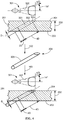
FIG. 4 schematically illustrates a method for forming a component with an insert configured to a fan-shaped channel, according to an embodiment of the present disclosure. -
FIG. 5 schematically illustrates a method for forming a component with an insert configured to a laidback fan-shaped channel, according to an embodiment of the present disclosure. -
FIG. 6 shows a sectional view, taken along the line 6-6 inFIG. 2 , looking in the direction of arrows applied thereto. -
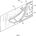
FIG. 7 shows a sectional view, taken along the line 7-7 inFIG. 2 , looking in the direction of arrows applied thereto. - The detailed description set forth below in connection with the appended drawings where like numerals reference like elements is intended as a description of various embodiments of the disclosed subject matter and is not intended to represent the only embodiments. Each embodiment described in this disclosure is provided merely as an example or illustration and should not be construed as preferred or advantageous over other embodiments. The illustrative examples provided herein are not intended to be exhaustive or to limit the claimed subject matter to the precise forms disclosed.
- Provided are components and an exemplary method of forming a component. Embodiments of the present disclosure, in comparison to components and method not utilizing one or more features disclosed herein, enable use of less cooling air, reduce component weight, reduce low cycle fatigue, and improve component life cycle.
- All numbers expressing quantities of ingredients and/or reaction conditions are to be understood as being modified in all instances by the term "about", unless otherwise indicated.
- All percentages and ratios are calculated by weight unless otherwise indicated. All percentages are calculated based on the total weight of a composition unless otherwise indicated. All component or composition levels are in reference to the active level of that component or composition, and are exclusive of impurities, for example, residual solvents or by-products, which may be present in commercially available sources.
- The articles "a" and "an," as used herein, mean one or more when applied to any feature in embodiments of the present invention described in the specification and claims. The use of "a" and "an" does not limit the meaning to a single feature unless such a limit is specifically stated. The article "the" preceding singular or plural nouns or noun phrases denotes a particular specified feature or particular specified features and may have a singular or plural connotation depending upon the context in which it is used. The adjective "any" means one, some, or all indiscriminately of whatever quantity.
- The term "at least one," as used herein, means one or more and thus includes individual components as well as mixtures/combinations.
- The term "comprising" (and its grammatical variations), as used herein, is used in the inclusive sense of "having" or "including" and not in the exclusive sense of "consisting only of."
- In accordance with the disclosure, the present invention may comprise a component including a channel and an insert. The component herein illustrated may comprise a metal or an alloy. In some embodiments, the alloy may comprise an HTW alloy. As used herein, the term "HTW alloy" is an alloy that exhibits liquation, hot and strain-age cracking, and which is therefore impractical to weld. In a further embodiment, the HTW alloy is a superalloy. The term "superalloy" is used herein as it is commonly used in the art; i.e., a highly corrosion and oxidation resistant alloy that exhibits excellent mechanical strength and resistance to creep at high temperatures.
- In some embodiments, the superalloy may include nickel-based superalloy, cobalt-based superalloy, iron-based superalloy, titanium-based superalloy, or combinations thereof. The superalloy may include, but not be limited to, a material selected from the group consisting of Hastelloy, Inconel alloys, Waspaloy, Rene alloys, such as GTD111, GTD222, GTD444, GTD262, Mar M247, IN100, IN 738, René 80, IN 939, René N2, René N4, René N5, René N6, René 65, René 77 (Udimet 700), René 80, René 88DT, René 104, René 108, René 125, René 142, René 195, René N500, René N515, IN 706, Nimonic 263, CM247, MarM247, CMSX-4, MGA1400, MGA2400, INCONEL 700, INCONEL 738, INCONEL 792, DS Siemet, CMSX10, PWA1480, PWA1483, PWA1484, TMS-75, TMS-82, Mar-M-200, UDIMET 500, ASTROLOY, and combinations thereof.
- As used herein, "ASTROLOY" refers to an alloy including a composition, by weight, of about 15% chromium, about 17% cobalt, about 5.3% molybdenum, about 4% aluminum, about 3.5% titanium, and a balance of nickel.
- As used herein, "DS Siemet" refers to an alloy including a composition, by weight, of about 9% cobalt, about 12.1% chromium, about 3.6% aluminum, about 4% titanium, about 5.2% tantalum, about 3.7% tungsten, about 1.8% molybdenum, and a balance of nickel.
- As used herein, "GTD111" refers to an alloy including a composition, by weight, of about 14% chromium, about 9.5% cobalt, about 3.8% tungsten, about 4.9% titanium, about 3% aluminum, about 0.1% iron, about 2.8% tantalum, about 1.6% molybdenum, about 0.1% carbon, and a balance of nickel.
- As used herein, "GTD262" refers to an alloy including a composition, by weight, of about 22.5% chromium, about 19% cobalt, about 2% tungsten, about 1.35% niobium, about 2.3% titanium, about 1.7% aluminum, about 0.1% carbon, and a balance of nickel.
- As used herein, "GTD444" refers to an alloy including a composition, by weight, of about 7.5% cobalt, about 0.2% iron, about 9.75% chromium, about 4.2% aluminum, about 3.5% titanium, about 4.8% tantalum, about 6% tungsten, about 1.5% molybdenum, about 0.5% niobium, about 0.2% silicon, about 0.15% hafnium, and a balance of nickel.
- As used herein, "MGA1400" refers to an alloy including a composition, by weight, of about 10% cobalt, about 14% chromium, about 4% aluminum, about 2.7% titanium, about 4.7% tantalum, about 4.3% tungsten, about 1.5% molybdenum, about 0.1% carbon, and a balance of nickel.
- As used herein, "MGA2400" refers to an alloy including a composition, by weight, of about 19% cobalt, about 19% chromium, about 1.9% aluminum, about 3.7% titanium, about 1.4% tantalum, about 6% tungsten, about 1% niobium, about 0.1% carbon, and a balance of nickel.
- As used herein, "PMA 1480" refers to an alloy including a composition, by weight, of about 10% chromium, about 5% cobalt, about 5% aluminum, about 1.5% titanium, about 12% tantalum, about 4% tungsten, and a balance of nickel.
- As used herein, "PWA1483" refers to an alloy including a composition, by weight, of about 9% cobalt, about 12.2% chromium, about 3.6% aluminum, about 4.1% titanium, about 5% tantalum, about 3.8% tungsten, about 1.9% molybdenum, and a balance of nickel.
- As used herein, "PMA 1484" refers to an alloy including a composition, by weight, of about 5% chromium, about 10% cobalt, about 2% molybdenum, about 5.6% aluminum, about 9% tantalum, about 6% tungsten, and a balance of nickel.
- As used herein, "René N2" refers to an alloy including a composition, by weight, of about 7.5% cobalt, about 13% chromium, about 6.6% aluminum, about 5% tantalum, about 3.8% tungsten, about 1.6% rhenium, about 0.15% hafnium, and a balance of nickel.
- As used herein, "René N4" refers to an alloy including a composition, by weight, of about 9.75% chromium, about 7.5% cobalt, about 4.2% aluminum, about 3.5% titanium, about 1.5% molybdenum, about 6.0% tungsten, about 4.8% tantalum, about 0.5% niobium, about 0.15% hafnium, and a balance of nickel.
- As used herein, "René N5" refers to an alloy including a composition, by weight, of about 7.5% cobalt, about 7.0% chromium, about 6.5% tantalum, about 6.2% aluminum, about 5.0% tungsten, about 3.0% rhenium, about 1.5% molybdenum, about 0.15% hafnium, and a balance of nickel.
- As used herein, "René N6" refers to an alloy including a composition, by weight, of about 12.5% cobalt, about 4.2% chromium, about 7.2% tantalum, about 5.75% aluminum, about 6% tungsten, about 5.4% rhenium, about 1.4% molybdenum, about 0.15% hafnium, and a balance of nickel.
- As used herein, "René 65" refers to an alloy including a composition, by weight, of about 13% cobalt, up to about 1.2% iron, about 16% chromium, about 2.1% aluminum, about 3.75% titanium, about 4% tungsten, about 4% molybdenum, about 0.7% niobium, up to about 0.15% manganese, and a balance of nickel.
- As used herein, "René 77 (Udimet 700)" refers to an alloy including a composition, by weight, of about 15% chromium, about 17% cobalt, about 5.3% molybdenum, about 3.35% titanium, about 4.2% aluminum, and a balance of nickel.
- As used herein, "René 80" refers to an alloy including a composition, by weight, of about 14% chromium, about 9.5% cobalt, about 4% molybdenum, about 3% aluminum, about 5% titanium, about 4% tungsten, about 0.17% carbon, and a balance of nickel.
- As used herein, "René 88DT" refers to an alloy including a composition, by weight, of about 16% chromium, about 13% cobalt, about 4% molybdenum, about 0.7% niobium, about 2.1% aluminum, about 3.7% titanium, about 4% tungsten, about 0.1% rhenium, a maximum of about 4.3% rhenium and tungsten, and a balance of nickel.
- As used herein, "René 104" refers to an alloy including a composition, by weight, of about 13.1% chromium, about 18.2% cobalt, about 3.8% molybdenum, about 1.9% tungsten, about 1.4% niobium, about 3.5% aluminum, about 3.5% titanium, about 2.7% tantalum, and a balance of nickel.
- As used herein, "René 108" refers to an alloy including a composition, by weight, of about 8.4% chromium, about 9.5% cobalt, about 5.5% aluminum, about 0.7% titanium, about 9.5% tungsten, about 0.5% molybdenum, about 3% tantalum, about 1.5% hafnium, and a balance of nickel.
- As used herein, "René 125" refers to an alloy including a composition, by weight, of about 8.5% chromium, about 10% cobalt, about 4.8% aluminum, up to about 2.5% titanium, about 8% tungsten, up to about 2% molybdenum, about 3.8% tantalum, about 1.4% hafnium, about 0.11% carbon, and a balance of nickel.
- As used herein, "René 142" refers to an alloy including a composition, by weight, of about 6.8% chromium, about 12% cobalt, about 6.1% aluminum, about 4.9% tungsten, about 1.5% molybdenum, about 2.8% rhenium, about 6.4% tantalum, about 1.5% hafnium, and a balance of nickel.
- As used herein, "René 195" refers to an alloy including a composition, by weight, of about 7.6% chromium, about 3.1% cobalt, about 7.8% aluminum, about 5.5% tantalum, about 0.1% molybdenum, about 3.9% tungsten, about 1.7% rhenium, about 0.15% hafnium, and a balance of nickel.
- As used herein, "René N500" refers to an alloy including a composition, by weight, of about 7.5% cobalt, about 0.2% iron, about 6% chromium, about 6.25% aluminum, about 6.5% tantalum, about 6.25% tungsten, about 1.5% molybdenum, about 0.15% hafnium, and a balance of nickel.
- As used herein, "René N515" refers to an alloy including a composition, by weight, of about 7.5% cobalt, about 0.2% iron, about 6% chromium, about 6.25% aluminum, about 6.5% tantalum, about 6.25% tungsten, about 2% molybdenum, about 0.1% niobium, about 1.5% rhenium, about 0.6% hafnium, and a balance of nickel.
- As used herein, "MarM247" and "CM247" refer to an alloy including a composition, by weight, of about 5.5% aluminum, about 0.15% carbon, about 8.25% chromium, about 10% cobalt, about 10% tungsten, about 0.7% molybdenum, about 0.5% iron, about 1% titanium, about 3% tantalum, about 1.5% hafnium, and a balance of nickel.
- As used herein, "IN100" refers to an alloy including a composition, by weight, of about 10% chromium, about 15% cobalt, about 3% molybdenum, about 4.7% titanium, about 5.5% aluminum, about 0.18% carbon, and a balance of nickel.
- As used herein, "INCONEL 700" refers to an alloy including a composition, by weight, of up to about 0.12% carbon, about 15% chromium, about 28.5% cobalt, about 3.75% molybdenum, about 2.2% titanium, about 3% aluminum, about 0.7% iron, up to about 0.3% silicon, up to about 0.1% manganese, and a balance of nickel.
- As used herein, "INCONEL 738" refers to an alloy including a composition, by weight, of about 0.17% carbon, about 16% chromium, about 8.5% cobalt, about 1.75% molybdenum, about 2.6% tungsten, about 3.4% titanium, about 3.4% aluminum, about 0.1% zirconium, about 2% niobium, and a balance of nickel.
- As used herein, "INCONEL 792" refers to an alloy including a composition, by weight, of about 12.4% chromium, about 9% cobalt, about 1.9% molybdenum, about 3.8% tungsten, about 3.9% tantalum, about 3.1% aluminum, about 4.5% titanium, about 0.12% carbon, about 0.1% zirconium, and a balance of nickel.
- As used herein, "UDIMET 500" refers to an alloy including a composition, by weight, of about 18.5% chromium, about 18.5% cobalt, about 4% molybdenum, about 3% titanium, about 3% aluminum, and a balance of nickel.
- As used herein, "Mar-M-200" refers to an alloy including a composition, by weight, of about 9% chromium, about 10% cobalt, about 12.5% tungsten, about 1% niobium, about 5% aluminum, about 2% titanium, about 10.14% carbon, about 1.8% hafnium, and a balance of nickel.
- As used herein, "TMS-75" refers to an alloy including a composition, by weight, of about 3% chromium, about 12% cobalt, about 2% molybdenum, about 6% tungsten, about 6% aluminum, about 6% tantalum, about 5% rhenium, about 0.1% hafnium, and a balance of nickel.
- As used herein, "TMS-82" refers to an alloy including a composition, by weight, of about 4.9% chromium, about 7.8% cobalt, about 1.9% molybdenum, about 2.4% rhenium, about 8.7% tungsten, about 5.3% aluminum, about 0.5% titanium, about 6% tantalum, about 0.1% hafnium, and a balance of nickel.
- As used herein, "CMSX-4" refers to an alloy including a composition, by weight, of about 6.4% chromium, about 9.6% cobalt, about 0.6% molybdenum, about 6.4% tungsten, about 5.6% aluminum, about 1.0% titanium, about 6.5% tantalum, about 3% rhenium, about 0.1% hafnium, and a balance of nickel.
- As used herein, "CMSX-10" refers to an alloy including a composition, by weight, of about 2% chromium, about 3% cobalt, about 0.4% molybdenum, about 5% tungsten, about 5.7% aluminum, about 0.2% titanium, about 8% tantalum, about 6% rhenium, and a balance of nickel.
- Any of the alloy compositions described herein may include incidental impurities.
- With reference to
FIG. 1 , a flow chart illustrating a method for forming a component is provided. The method for forming a component includes forming a channel configured to extend through a wall thickness of the component from an inner surface of the component to an outer surface of the component (step 101). The channel is defined by an inner channel surface. The method further includes forming an insert (step 102). The method further includes a step of attaching the insert onto the inner channel surface. The insert is configured to permit flow of cooling fluid such as air (step 103). - When the
insert 304 is attached on the inner channel surface 302 (see for exampleFig. 3 ), the attached insert provides extra length of the hole to increase film cooling effectiveness. The cooling fluid flows for convective cooling through the internal cooling passages and is subsequently deflected to external film cooling through film cooling holes onto the surface of turbine components. This method according to the present disclosure can be utilized to enable effective film cooling in sections having a reduced wall thickness in new parts or existing parts. This method according to the present disclosure can also enable use of less cooling air, reduce component weight, reduce low cycle fatigue, and improve component life cycle. - In certain embodiments, the forming
step 102 may include, but not be limited to 3D printing, metal injection molding (MIM), casting, advanced machining methods, or combinations thereof. - In certain embodiments, the attaching
step 103 may include, but not be limited to, brazing, welding, mechanical fit or combinations thereof. - With reference to
FIG. 2 , acoated article 200 may be aturbine component 201. Theturbine component 201 may be selected from the group consisting of at least one of hot gas path components, combustion components, blades (buckets), vanes (nozzles), shrouds, combustor liners, transition ducts, cross fire tube collars, venturis, transition piece seals, and fuel nozzle parts. Theturbine component 201 may include at least oneplenum 205 as shown. The plenums are internally connected to cooling holes 303. Cooling fluid flows from theplenums 205 through a passageway defined in an airfoil of theturbine component 201 and discharges through the cooling holes 303. - With reference to
FIG. 3 , acomponent 201 including achannel 301 having a cylindrical geometry also expanded above in a top view, and aninsert 304 is provided. Thechannel 301 is configured to extend through awall thickness 202 of thecomponent 201 from aninner surface 203 of the component to anouter surface 204 of thecomponent 201 and is defined by an inner channel surface 302 (step 101). Theinsert 304 is configured to permit flow of cooling fluid such as air and has anouter insert surface 305 corresponding to and attached to the inner channel surface 302 (step 102). In certain embodiments, theinsert 304 may be attached to theinner channel surface 302 by a braze, weld, or combinations thereof (step 103). The insert 208 may include a combination of a superalloy powder and a braze matrix, wherein the superalloy powder has a higher melting temperature than the braze matrix. - With reference to
FIG. 4 , acomponent 201 including achannel 301, having a fan-shaped geometry, also expanded above in a top view, and aninsert 304 is provided. Thechannel 301 is configured to extend through awall thickness 202 of thecomponent 201 from aninner surface 203 of the component to anouter surface 204 of thecomponent 201 and is defined by an inner channel surface 302 (step 101). Theinsert 304 is configured to permit flow of cooling fluid such as air and has anouter insert surface 305 corresponding to and attached to the inner channel surface 302 (step 102). In certain embodiments, theinsert 304 may be attached to theinner channel surface 302 by a braze, weld, or combinations thereof (step 103). Theinsert 304 may include a combination of a superalloy powder and a braze matrix, wherein the superalloy powder has a higher melting temperature than the braze matrix. - With reference to
FIG. 5 , acomponent 201 including achannel 301, having a laidback fan-shaped geometry, also expanded above in a top view, and aninsert 304 is provided. Thechannel 301 is configured to extend through awall thickness 202 of thecomponent 201 from aninner surface 203 of the component to anouter surface 204 of thecomponent 201 and is defined by an inner channel surface 302 (step 101). Theinsert 304 is configured to permit flow of cooling fluid such as air and has anouter insert surface 305 corresponding to and attached to the inner channel surface 302 (step 102). In certain embodiments, theinsert 304 may be attached to theinner channel surface 302 by a braze, weld, or combinations thereof (step 103). Theinsert 304 may include a combination of a superalloy powder and a braze matrix, wherein the superalloy powder has a higher melting temperature than the braze matrix. - In certain embodiments, a turbine component including a
channel 301 and aninsert 304 is provided.Channel 301 is configured to extend through a wall thickness of the component from aninner surface 203 of the component to anouter surface 204 of the component and is defined by aninner channel surface 302. The insert is configured to permit flow of cooling fluid such as air and has anouter insert surface 305 corresponding to and attached to theinner channel surface 302. The insert has a protruded portion 306 protruding from the inner surface of the turbine component. - In certain embodiments, insert 304 may protrude from the
inner surface 203 of the component. In certain embodiments, insert 304 may protrude from theouter surface 204 of the component. In yet other embodiments, insert 304 may protrude from both theinner surface 203 andouter surface 204 of the component. In some embodiments, insert 304 can have a protruded portion from the inner surface and/or outer surface from 0.010 inch to 0.080 inch. - In certain embodiments,
turbine component 201 may include blades (buckets), vanes (nozzles), shrouds, combustors, transition ducts, and combinations thereof. - With reference to
FIG. 6 , a part of aturbine component 201 includingplenums 205 shows a sectional view, taken along the line 6-6 inFIG. 2 . Theplenums 205 are internally and fluidly connected to cooling holes 303. Aninsert 304 can be attached to the cooling holes 303, thereby providing extra length of the hole to increase film cooling effectiveness. This is especially effective when the wall thickness of the casting between theplenums 205 and the hot gas path surface is insufficient. Theinsert 304 can have a geometry selected from the group consisting of a cylindrical geometry, a fan-shaped geometry, a laidback fan-shaped geometry, and combinations thereof, depending on the geometry of the channel. - With reference to
FIG. 7 , acoated article 200 including aturbine component 201 shows a sectional view, taken along the line 7-7 inFIG. 2 . Thecoated article 200 includes cooling holes 303. Aninsert 304 can be attached to the cooling holes 303, thereby providing extra length of the hole to increase film cooling effectiveness. Theinsert 304 can have a geometry selected from the group consisting of a cylindrical geometry, a fan-shaped geometry, a laidback fan-shaped geometry, and combinations thereof, depending on the geometry of the channel. - While the invention has been described with reference to a preferred embodiment, it will be understood by those skilled in the art that various changes may be made and equivalents may be substituted for elements thereof without departing from the scope of the invention. In addition, many modifications may be made to adapt a particular situation or material to the teachings of the invention without departing from the essential scope thereof. Therefore, it is intended that the invention not be limited to the particular embodiment disclosed as the best mode contemplated for carrying out this invention, but that the invention will include all embodiments falling within the scope of the appended claims.
- Various aspects and embodiments of the present invention are defined by the following clauses:
- 1. A component comprising:
- a channel configured to extend through a wall thickness of the component from an inner surface of the component to an outer surface of the component, the channel being defined by an inner channel surface; and
- an insert configured to permit flow of cooling fluid, the insert having an outer insert surface corresponding to and attached to the inner channel surface.
- 2. The component according to clause 1, wherein the insert protrudes from the inner surface of the component.
- 3. The component according to clause 1, wherein the insert is manufactured by a process selected from the group consisting of 3D printing, metal injection molding, casting, advanced machining methods and combinations thereof.
- 4. The component according to clause 1, wherein the insert comprises a combination of a superalloy powder and a braze matrix, wherein the superalloy powder has a higher melting temperature than the braze matrix.
- 5. The component according to clause 1, wherein the channel comprises a geometry selected from the group consisting of a cylindrical geometry, a fan-shaped geometry, a laidback fan-shaped geometry, and combinations thereof.
- 6. The component according to clause 1, wherein the insert is attached to the inner channel surface by a braze, weld, or combinations thereof.
- 7. The component according to clause 1, wherein the component comprises a material selected from the group consisting of metal, alloy, and combinations thereof.
- 8. The component according to clause 8, wherein the component comprises a hard-to-weld (HTW) alloy material selected from the group consisting of superalloy, nickel-based superalloy, cobalt-based superalloy, iron-based superalloy, titanium-based superalloy and combinations thereof.
- 9. A turbine component comprising:
- a channel configured to extend through a wall thickness of the turbine component from an inner surface of the turbine component to an outer surface of the turbine component, the channel being defined by an inner channel surface; and
- an insert configured to permit flow of cooling fluid, the insert having an outer insert surface corresponding to and attached to the inner channel surface,
- wherein the insert has a protruded portion protruding from the inner surface of the turbine component.
- 10. The turbine component according to clause 9, wherein the outer insert surface is welded or brazed onto the inner channel surface.
- 11. The turbine component according to clause 9, wherein the component comprises a material selected from the group consisting of metal, alloy, and combinations thereof.
- 12. The turbine component according to clause 11, wherein the turbine component comprises a hard-to-weld (HTW) alloy material selected from the group consisting of superalloy, nickel-based superalloy, cobalt-based superalloy, iron-based superalloy, titanium-based superalloy and combinations thereof.
- 13. A method for forming a component comprising the steps of:
- forming a channel configured to extend through a wall thickness of the component from an inner surface of the component to an outer surface of the component, the channel being defined by an inner channel surface; and
- forming an insert;
- attaching the insert onto the inner channel surface, the insert being configured to permit flow of cooling fluid.
- 14. The method according to clause 13, wherein the insert protrudes from the inner surface of the component.
- 15. The method according to clause 13, the component is a turbine component.
- 16. The method according to clause 13, wherein the insert is formed by a process selected from the group consisting of 3D printing, metal injection molding, casting, advanced machining methods and combinations thereof.
- 17. The method according to clause 13, wherein the insert is a combination of a superalloy powder and a braze matrix, wherein the superalloy powder has a higher melting temperature than braze matrix.
- 18. The method according to clause 13, wherein the attaching is performed by a process selected from the group consisting of brazing, welding, mechanical fit and combinations thereof.
- 19. The method according to clause 13, wherein the channel comprises a geometry selected from the group consisting of a cylindrical geometry, a fan-shaped geometry, a laidback fan-shaped geometry, and combinations thereof.
- 20. The method according to clause 13, wherein the component comprises a hard-to-weld (HTW) alloy material selected from the group consisting of superalloy, nickel-based superalloy, cobalt-based superalloy, iron-based superalloy, titanium-based superalloy and combinations thereof.
Claims (14)
- A component (201) comprising:a channel (301) configured to extend through a wall thickness (202) of the component (201) from an inner surface (203) of the component (201) to an outer surface (204) of the component (201), the channel (301) being defined by an inner channel surface (302); andan insert (208) configured to permit flow of cooling fluid, the insert (208) having an outer insert surface (305) corresponding to and attached to the inner channel surface (302).
- The component (201) according to claim 1, wherein the insert (208) protrudes from the inner surface (203) of the component (201).
- The component (201) according to claim 1 or 2, wherein the insert (208) comprises a combination of a superalloy powder and a braze matrix, wherein the superalloy powder has a higher melting temperature than the braze matrix.
- The component (201) according to any one of claims 1 to 3, wherein the channel (301) comprises a geometry selected from the group consisting of a cylindrical geometry, a fan-shaped geometry, a laidback fan-shaped geometry, and combinations thereof.
- The component (201) according to any one of claims 1 to 4, wherein the component (201) comprises a material selected from the group consisting of metal, alloy, and combinations thereof.
- The component (201) according to claim 5, wherein the component (201) comprises a hard-to-weld (HTW) alloy material selected from the group consisting of superalloy, nickel-based superalloy, cobalt-based superalloy, iron-based superalloy, titanium-based superalloy and combinations thereof.
- A method (100) for forming a component (201) comprising the steps of:forming (101) a channel (301) configured to extend through a wall thickness (202) of the component (201) from an inner surface (203) of the component (201) to an outer surface (204) of the component (201), the channel (301) being defined by an inner channel surface (302); andforming (102) an insert (208);attaching (103) the insert (208) onto the inner channel surface (302), the insert (208) being configured to permit flow of cooling fluid.
- The method (100) according to claim 7, wherein the insert (208) is formed by a process selected from the group consisting of 3D printing, metal injection molding, casting, advanced machining methods and combinations thereof.
- The method (100) according to claim 7 or 8, wherein the attaching (103) is performed by a process selected from the group consisting of brazing, welding, mechanical fit and combinations thereof.
- The method (100) according to any one of claims 7 to 9, wherein the channel (301) comprises a geometry selected from the group consisting of a cylindrical geometry, a fan-shaped geometry, a laidback fan-shaped geometry, and combinations thereof.
- The method (100) according to any one of claims 7 to 10, wherein the insert (208) is a combination of a superalloy powder and a braze matrix, wherein the superalloy powder has a higher melting temperature than braze matrix.
- A turbine component (201) comprising:a channel (301) configured to extend through a wall thickness of the turbine component (201) from an inner surface (302) of the turbine component (201) to an outer surface (204) of the turbine component (201), the channel (301) being defined by an inner channel surface (302); andan insert (304) configured to permit flow of cooling fluid, the insert (304) having an outer insert surface (305) corresponding to and attached to the inner channel surface (302),wherein the insert (304) has a protruded portion (306) protruding from the inner surface (302) of the turbine component (201).
- The turbine component (201) according to claim 12, wherein the outer insert surface (305) is welded or brazed onto the inner channel surface (302).
- The turbine component (201) according to claim 12 or 13, wherein the component (201) comprises a material selected from the group consisting of metal, alloy, and combinations thereof.
Applications Claiming Priority (1)
| Application Number | Priority Date | Filing Date | Title |
|---|---|---|---|
| US15/412,710 US10619499B2 (en) | 2017-01-23 | 2017-01-23 | Component and method for forming a component |
Publications (1)
| Publication Number | Publication Date |
|---|---|
| EP3351730A1 true EP3351730A1 (en) | 2018-07-25 |
Family
ID=60997384
Family Applications (1)
| Application Number | Title | Priority Date | Filing Date |
|---|---|---|---|
| EP18151936.4A Withdrawn EP3351730A1 (en) | 2017-01-23 | 2018-01-16 | Component and method for forming a component |
Country Status (3)
| Country | Link |
|---|---|
| US (1) | US10619499B2 (en) |
| EP (1) | EP3351730A1 (en) |
| JP (1) | JP7757021B2 (en) |
Cited By (3)
| Publication number | Priority date | Publication date | Assignee | Title |
|---|---|---|---|---|
| EP4253723A1 (en) * | 2022-03-31 | 2023-10-04 | General Electric Company | Cooling passage exit opening cross-sectional area reduction for turbine system component |
| FR3144768A1 (en) * | 2023-01-11 | 2024-07-12 | Safran Aircraft Engines | Process for manufacturing a high-pressure turbine part with air film cooling |
| US12203387B2 (en) | 2022-03-31 | 2025-01-21 | Ge Infrastructure Technology Llc | Thermal profile based redirection of turbine system component coolant by targeted alteration of cooling passage exit opening cross-sectional area |
Families Citing this family (13)
| Publication number | Priority date | Publication date | Assignee | Title |
|---|---|---|---|---|
| DE102018206259A1 (en) * | 2018-04-24 | 2019-10-24 | MTU Aero Engines AG | GUIDE SHOVEL FOR A TURBINE OF A FLOW MACHINE |
| KR102226326B1 (en) * | 2019-11-26 | 2021-03-11 | 김정민 | Cross-fire tube for MS6001 Gas turbine |
| US11732590B2 (en) | 2021-08-13 | 2023-08-22 | Raytheon Technologies Corporation | Transition section for accommodating mismatch between other sections of a cooling aperture in a turbine engine component |
| US11542831B1 (en) | 2021-08-13 | 2023-01-03 | Raytheon Technologies Corporation | Energy beam positioning during formation of a cooling aperture |
| US12123839B2 (en) | 2021-08-13 | 2024-10-22 | Rtx Corporation | Forming and/or inspecting cooling aperture(s) in a turbine engine component |
| US11673200B2 (en) | 2021-08-13 | 2023-06-13 | Raytheon Technologies Corporation | Forming cooling aperture(s) using electrical discharge machining |
| US11898465B2 (en) | 2021-08-13 | 2024-02-13 | Rtx Corporation | Forming lined cooling aperture(s) in a turbine engine component |
| US11913119B2 (en) | 2021-08-13 | 2024-02-27 | Rtx Corporation | Forming cooling aperture(s) in a turbine engine component |
| US11603769B2 (en) | 2021-08-13 | 2023-03-14 | Raytheon Technologies Corporation | Forming lined cooling aperture(s) in a turbine engine component |
| US11813706B2 (en) | 2021-08-13 | 2023-11-14 | Rtx Corporation | Methods for forming cooling apertures in a turbine engine component |
| JP2024001478A (en) * | 2022-06-22 | 2024-01-10 | 三菱重工業株式会社 | How to manufacture turbine parts |
| CN119778049A (en) * | 2023-10-05 | 2025-04-08 | 通用电气技术有限公司 | Thermally-distributed redirection of coolant from turbine system components by targeted change of cooling channel outlet opening cross-sectional area |
| CN120002468B (en) * | 2025-03-25 | 2025-10-31 | 哈尔滨汽轮机厂有限责任公司 | A method for controlling the inner bore dimension in the split machining of a split thin-walled cylinder |
Citations (4)
| Publication number | Priority date | Publication date | Assignee | Title |
|---|---|---|---|---|
| US4638628A (en) * | 1978-10-26 | 1987-01-27 | Rice Ivan G | Process for directing a combustion gas stream onto rotatable blades of a gas turbine |
| US20070036942A1 (en) * | 2005-08-11 | 2007-02-15 | Rolls-Royce Plc | Cooling method and apparatus |
| EP2230381A2 (en) * | 2009-03-18 | 2010-09-22 | General Electric Company | Method of using and reconstructing a film-cooling augmentation device for a turbine airfoil |
| EP2679771A1 (en) * | 2012-06-25 | 2014-01-01 | General Electric Company | Systems and methods to control flow in a rotor wheel |
Family Cites Families (19)
| Publication number | Priority date | Publication date | Assignee | Title |
|---|---|---|---|---|
| DE3629910A1 (en) * | 1986-09-03 | 1988-03-17 | Mtu Muenchen Gmbh | METAL HOLLOW COMPONENT WITH A METAL INSERT, IN PARTICULAR TURBINE BLADE WITH COOLING INSERT |
| US6214248B1 (en) * | 1998-11-12 | 2001-04-10 | General Electric Company | Method of forming hollow channels within a component |
| US6158955A (en) * | 1999-06-03 | 2000-12-12 | General Electric Company | Welding method and assembly therefor |
| DE19960797C1 (en) | 1999-12-16 | 2001-09-13 | Mtu Aero Engines Gmbh | Method for producing an opening in a metallic component |
| US6530971B1 (en) * | 2001-01-29 | 2003-03-11 | General Electric Company | Nickel-base braze material and braze repair method |
| US6663919B2 (en) * | 2002-03-01 | 2003-12-16 | General Electric Company | Process of removing a coating deposit from a through-hole in a component and component processed thereby |
| US7316539B2 (en) * | 2005-04-07 | 2008-01-08 | Siemens Power Generation, Inc. | Vane assembly with metal trailing edge segment |
| EP1847684A1 (en) * | 2006-04-21 | 2007-10-24 | Siemens Aktiengesellschaft | Turbine blade |
| EP1923536A1 (en) * | 2006-11-17 | 2008-05-21 | Siemens Aktiengesellschaft | Liner in a cooling channel of a turbine blade |
| US8281600B2 (en) * | 2007-01-09 | 2012-10-09 | General Electric Company | Thimble, sleeve, and method for cooling a combustor assembly |
| US8052378B2 (en) | 2009-03-18 | 2011-11-08 | General Electric Company | Film-cooling augmentation device and turbine airfoil incorporating the same |
| US9056372B2 (en) * | 2010-10-12 | 2015-06-16 | Alstom Technology Ltd | Extending useful life of a cobalt-based gas turbine component |
| US9353687B1 (en) * | 2012-10-18 | 2016-05-31 | Florida Turbine Technologies, Inc. | Gas turbine engine with liquid metal cooling |
| US20140212628A1 (en) * | 2013-01-30 | 2014-07-31 | General Electric Company | Multilayer component and fabrication process |
| KR20150131295A (en) * | 2013-03-15 | 2015-11-24 | 지멘스 에너지, 인코포레이티드 | Presintered preform for repair of superalloy component |
| US9581028B1 (en) * | 2014-02-24 | 2017-02-28 | Florida Turbine Technologies, Inc. | Small turbine stator vane with impingement cooling insert |
| US9970319B2 (en) | 2014-05-05 | 2018-05-15 | United Technologies Corporation | Reducing variation in cooling hole meter length |
| EP2957833B1 (en) * | 2014-06-17 | 2018-10-24 | Rolls-Royce Corporation | Combustor assembly with chutes |
| US10208602B2 (en) * | 2015-04-27 | 2019-02-19 | United Technologies Corporation | Asymmetric diffuser opening for film cooling holes |
-
2017
- 2017-01-23 US US15/412,710 patent/US10619499B2/en active Active
-
2018
- 2018-01-11 JP JP2018002286A patent/JP7757021B2/en active Active
- 2018-01-16 EP EP18151936.4A patent/EP3351730A1/en not_active Withdrawn
Patent Citations (4)
| Publication number | Priority date | Publication date | Assignee | Title |
|---|---|---|---|---|
| US4638628A (en) * | 1978-10-26 | 1987-01-27 | Rice Ivan G | Process for directing a combustion gas stream onto rotatable blades of a gas turbine |
| US20070036942A1 (en) * | 2005-08-11 | 2007-02-15 | Rolls-Royce Plc | Cooling method and apparatus |
| EP2230381A2 (en) * | 2009-03-18 | 2010-09-22 | General Electric Company | Method of using and reconstructing a film-cooling augmentation device for a turbine airfoil |
| EP2679771A1 (en) * | 2012-06-25 | 2014-01-01 | General Electric Company | Systems and methods to control flow in a rotor wheel |
Cited By (5)
| Publication number | Priority date | Publication date | Assignee | Title |
|---|---|---|---|---|
| EP4253723A1 (en) * | 2022-03-31 | 2023-10-04 | General Electric Company | Cooling passage exit opening cross-sectional area reduction for turbine system component |
| US11859512B2 (en) | 2022-03-31 | 2024-01-02 | General Electric Company | Cooling passage exit opening cross-sectional area reduction for turbine system component |
| US12203387B2 (en) | 2022-03-31 | 2025-01-21 | Ge Infrastructure Technology Llc | Thermal profile based redirection of turbine system component coolant by targeted alteration of cooling passage exit opening cross-sectional area |
| US12428964B2 (en) | 2022-03-31 | 2025-09-30 | Ge Infrastructure Technology Llc | Cooling passage exit opening cross-sectional area reduction for turbine system component |
| FR3144768A1 (en) * | 2023-01-11 | 2024-07-12 | Safran Aircraft Engines | Process for manufacturing a high-pressure turbine part with air film cooling |
Also Published As
| Publication number | Publication date |
|---|---|
| US10619499B2 (en) | 2020-04-14 |
| JP7757021B2 (en) | 2025-10-21 |
| JP2018128009A (en) | 2018-08-16 |
| US20180209285A1 (en) | 2018-07-26 |
Similar Documents
| Publication | Publication Date | Title |
|---|---|---|
| US10619499B2 (en) | Component and method for forming a component | |
| US6634860B2 (en) | Foil formed structure for turbine airfoil tip | |
| US11559847B2 (en) | Superalloy part and method of processing | |
| EP3877629B1 (en) | Turbomachine blade tip attachment | |
| EP3345718A1 (en) | Structure braze repair of hard-to-weld superalloy components using diffusion alloy insert | |
| US11384414B2 (en) | Nickel-based superalloys | |
| US20030118445A1 (en) | Foil formed structure for turbine airfoil | |
| US20230147399A1 (en) | Joining individual turbine vanes with field assisted sintering technology (fast) | |
| EP3318364A1 (en) | Threaded coupon for repair of superalloy part | |
| US20200061662A1 (en) | Protecting hole in component during coating process using plug with water soluble layer | |
| US6640546B2 (en) | Foil formed cooling area enhancement | |
| CN108798802B (en) | Method for providing a cooling structure for a component | |
| JP7451512B2 (en) | Airfoil coupon installation | |
| US10227878B2 (en) | Article and method of forming an article | |
| JP7224768B2 (en) | Clad article and method of forming the clad article | |
| CN116926382A (en) | Compositions, articles, and methods of forming the same | |
| EP2985357B1 (en) | Die-castable nickel based superalloy composition | |
| EP3381602A1 (en) | Hybrid component with multiple cores and method for treating a component | |
| CN109083685B (en) | Cooling arrangement and method of creating a cooling arrangement | |
| CN118814024A (en) | Compositions, articles and methods of forming the same |
Legal Events
| Date | Code | Title | Description |
|---|---|---|---|
| PUAI | Public reference made under article 153(3) epc to a published international application that has entered the european phase |
Free format text: ORIGINAL CODE: 0009012 |
|
| STAA | Information on the status of an ep patent application or granted ep patent |
Free format text: STATUS: THE APPLICATION HAS BEEN PUBLISHED |
|
| AK | Designated contracting states |
Kind code of ref document: A1 Designated state(s): AL AT BE BG CH CY CZ DE DK EE ES FI FR GB GR HR HU IE IS IT LI LT LU LV MC MK MT NL NO PL PT RO RS SE SI SK SM TR |
|
| AX | Request for extension of the european patent |
Extension state: BA ME |
|
| STAA | Information on the status of an ep patent application or granted ep patent |
Free format text: STATUS: REQUEST FOR EXAMINATION WAS MADE |
|
| 17P | Request for examination filed |
Effective date: 20190125 |
|
| RBV | Designated contracting states (corrected) |
Designated state(s): AL AT BE BG CH CY CZ DE DK EE ES FI FR GB GR HR HU IE IS IT LI LT LU LV MC MK MT NL NO PL PT RO RS SE SI SK SM TR |
|
| STAA | Information on the status of an ep patent application or granted ep patent |
Free format text: STATUS: EXAMINATION IS IN PROGRESS |
|
| 17Q | First examination report despatched |
Effective date: 20190820 |
|
| STAA | Information on the status of an ep patent application or granted ep patent |
Free format text: STATUS: THE APPLICATION IS DEEMED TO BE WITHDRAWN |
|
| 18D | Application deemed to be withdrawn |
Effective date: 20201117 |