EP3351727A2 - Bonded fan platform - Google Patents
Bonded fan platform Download PDFInfo
- Publication number
- EP3351727A2 EP3351727A2 EP18155348.8A EP18155348A EP3351727A2 EP 3351727 A2 EP3351727 A2 EP 3351727A2 EP 18155348 A EP18155348 A EP 18155348A EP 3351727 A2 EP3351727 A2 EP 3351727A2
- Authority
- EP
- European Patent Office
- Prior art keywords
- platform
- fan blade
- turbine engine
- gas turbine
- platform half
- Prior art date
- Legal status (The legal status is an assumption and is not a legal conclusion. Google has not performed a legal analysis and makes no representation as to the accuracy of the status listed.)
- Granted
Links
Images




Classifications
-
- F—MECHANICAL ENGINEERING; LIGHTING; HEATING; WEAPONS; BLASTING
- F01—MACHINES OR ENGINES IN GENERAL; ENGINE PLANTS IN GENERAL; STEAM ENGINES
- F01D—NON-POSITIVE DISPLACEMENT MACHINES OR ENGINES, e.g. STEAM TURBINES
- F01D5/00—Blades; Blade-carrying members; Heating, heat-insulating, cooling or antivibration means on the blades or the members
- F01D5/30—Fixing blades to rotors; Blade roots ; Blade spacers
- F01D5/3069—Fixing blades to rotors; Blade roots ; Blade spacers between two discs or rings
-
- F—MECHANICAL ENGINEERING; LIGHTING; HEATING; WEAPONS; BLASTING
- F01—MACHINES OR ENGINES IN GENERAL; ENGINE PLANTS IN GENERAL; STEAM ENGINES
- F01D—NON-POSITIVE DISPLACEMENT MACHINES OR ENGINES, e.g. STEAM TURBINES
- F01D11/00—Preventing or minimising internal leakage of working-fluid, e.g. between stages
- F01D11/005—Sealing means between non relatively rotating elements
-
- F—MECHANICAL ENGINEERING; LIGHTING; HEATING; WEAPONS; BLASTING
- F01—MACHINES OR ENGINES IN GENERAL; ENGINE PLANTS IN GENERAL; STEAM ENGINES
- F01D—NON-POSITIVE DISPLACEMENT MACHINES OR ENGINES, e.g. STEAM TURBINES
- F01D5/00—Blades; Blade-carrying members; Heating, heat-insulating, cooling or antivibration means on the blades or the members
- F01D5/12—Blades
-
- F—MECHANICAL ENGINEERING; LIGHTING; HEATING; WEAPONS; BLASTING
- F01—MACHINES OR ENGINES IN GENERAL; ENGINE PLANTS IN GENERAL; STEAM ENGINES
- F01D—NON-POSITIVE DISPLACEMENT MACHINES OR ENGINES, e.g. STEAM TURBINES
- F01D5/00—Blades; Blade-carrying members; Heating, heat-insulating, cooling or antivibration means on the blades or the members
- F01D5/12—Blades
- F01D5/14—Form or construction
- F01D5/147—Construction, i.e. structural features, e.g. of weight-saving hollow blades
-
- F—MECHANICAL ENGINEERING; LIGHTING; HEATING; WEAPONS; BLASTING
- F01—MACHINES OR ENGINES IN GENERAL; ENGINE PLANTS IN GENERAL; STEAM ENGINES
- F01D—NON-POSITIVE DISPLACEMENT MACHINES OR ENGINES, e.g. STEAM TURBINES
- F01D5/00—Blades; Blade-carrying members; Heating, heat-insulating, cooling or antivibration means on the blades or the members
- F01D5/30—Fixing blades to rotors; Blade roots ; Blade spacers
- F01D5/3053—Fixing blades to rotors; Blade roots ; Blade spacers by means of pins
-
- F—MECHANICAL ENGINEERING; LIGHTING; HEATING; WEAPONS; BLASTING
- F04—POSITIVE - DISPLACEMENT MACHINES FOR LIQUIDS; PUMPS FOR LIQUIDS OR ELASTIC FLUIDS
- F04D—NON-POSITIVE-DISPLACEMENT PUMPS
- F04D29/00—Details, component parts, or accessories
- F04D29/02—Selection of particular materials
- F04D29/023—Selection of particular materials especially adapted for elastic fluid pumps
-
- F—MECHANICAL ENGINEERING; LIGHTING; HEATING; WEAPONS; BLASTING
- F04—POSITIVE - DISPLACEMENT MACHINES FOR LIQUIDS; PUMPS FOR LIQUIDS OR ELASTIC FLUIDS
- F04D—NON-POSITIVE-DISPLACEMENT PUMPS
- F04D29/00—Details, component parts, or accessories
- F04D29/26—Rotors specially for elastic fluids
- F04D29/32—Rotors specially for elastic fluids for axial flow pumps
- F04D29/321—Rotors specially for elastic fluids for axial flow pumps for axial flow compressors
- F04D29/324—Blades
-
- F—MECHANICAL ENGINEERING; LIGHTING; HEATING; WEAPONS; BLASTING
- F01—MACHINES OR ENGINES IN GENERAL; ENGINE PLANTS IN GENERAL; STEAM ENGINES
- F01D—NON-POSITIVE DISPLACEMENT MACHINES OR ENGINES, e.g. STEAM TURBINES
- F01D11/00—Preventing or minimising internal leakage of working-fluid, e.g. between stages
- F01D11/005—Sealing means between non relatively rotating elements
- F01D11/006—Sealing the gap between rotor blades or blades and rotor
- F01D11/008—Sealing the gap between rotor blades or blades and rotor by spacer elements between the blades, e.g. independent interblade platforms
-
- F—MECHANICAL ENGINEERING; LIGHTING; HEATING; WEAPONS; BLASTING
- F01—MACHINES OR ENGINES IN GENERAL; ENGINE PLANTS IN GENERAL; STEAM ENGINES
- F01D—NON-POSITIVE DISPLACEMENT MACHINES OR ENGINES, e.g. STEAM TURBINES
- F01D5/00—Blades; Blade-carrying members; Heating, heat-insulating, cooling or antivibration means on the blades or the members
- F01D5/12—Blades
- F01D5/28—Selecting particular materials; Particular measures relating thereto; Measures against erosion or corrosion
- F01D5/282—Selecting composite materials, e.g. blades with reinforcing filaments
-
- F—MECHANICAL ENGINEERING; LIGHTING; HEATING; WEAPONS; BLASTING
- F02—COMBUSTION ENGINES; HOT-GAS OR COMBUSTION-PRODUCT ENGINE PLANTS
- F02K—JET-PROPULSION PLANTS
- F02K3/00—Plants including a gas turbine driving a compressor or a ducted fan
- F02K3/02—Plants including a gas turbine driving a compressor or a ducted fan in which part of the working fluid by-passes the turbine and combustion chamber
- F02K3/04—Plants including a gas turbine driving a compressor or a ducted fan in which part of the working fluid by-passes the turbine and combustion chamber the plant including ducted fans, i.e. fans with high volume, low pressure outputs, for augmenting the jet thrust, e.g. of double-flow type
- F02K3/06—Plants including a gas turbine driving a compressor or a ducted fan in which part of the working fluid by-passes the turbine and combustion chamber the plant including ducted fans, i.e. fans with high volume, low pressure outputs, for augmenting the jet thrust, e.g. of double-flow type with front fan
-
- F—MECHANICAL ENGINEERING; LIGHTING; HEATING; WEAPONS; BLASTING
- F05—INDEXING SCHEMES RELATING TO ENGINES OR PUMPS IN VARIOUS SUBCLASSES OF CLASSES F01-F04
- F05D—INDEXING SCHEME FOR ASPECTS RELATING TO NON-POSITIVE-DISPLACEMENT MACHINES OR ENGINES, GAS-TURBINES OR JET-PROPULSION PLANTS
- F05D2220/00—Application
- F05D2220/30—Application in turbines
- F05D2220/36—Application in turbines specially adapted for the fan of turbofan engines
-
- F—MECHANICAL ENGINEERING; LIGHTING; HEATING; WEAPONS; BLASTING
- F05—INDEXING SCHEMES RELATING TO ENGINES OR PUMPS IN VARIOUS SUBCLASSES OF CLASSES F01-F04
- F05D—INDEXING SCHEME FOR ASPECTS RELATING TO NON-POSITIVE-DISPLACEMENT MACHINES OR ENGINES, GAS-TURBINES OR JET-PROPULSION PLANTS
- F05D2240/00—Components
- F05D2240/80—Platforms for stationary or moving blades
-
- F—MECHANICAL ENGINEERING; LIGHTING; HEATING; WEAPONS; BLASTING
- F05—INDEXING SCHEMES RELATING TO ENGINES OR PUMPS IN VARIOUS SUBCLASSES OF CLASSES F01-F04
- F05D—INDEXING SCHEME FOR ASPECTS RELATING TO NON-POSITIVE-DISPLACEMENT MACHINES OR ENGINES, GAS-TURBINES OR JET-PROPULSION PLANTS
- F05D2240/00—Components
- F05D2240/80—Platforms for stationary or moving blades
- F05D2240/81—Cooled platforms
-
- F—MECHANICAL ENGINEERING; LIGHTING; HEATING; WEAPONS; BLASTING
- F05—INDEXING SCHEMES RELATING TO ENGINES OR PUMPS IN VARIOUS SUBCLASSES OF CLASSES F01-F04
- F05D—INDEXING SCHEME FOR ASPECTS RELATING TO NON-POSITIVE-DISPLACEMENT MACHINES OR ENGINES, GAS-TURBINES OR JET-PROPULSION PLANTS
- F05D2260/00—Function
- F05D2260/30—Retaining components in desired mutual position
-
- F—MECHANICAL ENGINEERING; LIGHTING; HEATING; WEAPONS; BLASTING
- F05—INDEXING SCHEMES RELATING TO ENGINES OR PUMPS IN VARIOUS SUBCLASSES OF CLASSES F01-F04
- F05D—INDEXING SCHEME FOR ASPECTS RELATING TO NON-POSITIVE-DISPLACEMENT MACHINES OR ENGINES, GAS-TURBINES OR JET-PROPULSION PLANTS
- F05D2260/00—Function
- F05D2260/30—Retaining components in desired mutual position
- F05D2260/36—Retaining components in desired mutual position by a form fit connection, e.g. by interlocking
-
- F—MECHANICAL ENGINEERING; LIGHTING; HEATING; WEAPONS; BLASTING
- F05—INDEXING SCHEMES RELATING TO ENGINES OR PUMPS IN VARIOUS SUBCLASSES OF CLASSES F01-F04
- F05D—INDEXING SCHEME FOR ASPECTS RELATING TO NON-POSITIVE-DISPLACEMENT MACHINES OR ENGINES, GAS-TURBINES OR JET-PROPULSION PLANTS
- F05D2300/00—Materials; Properties thereof
- F05D2300/60—Properties or characteristics given to material by treatment or manufacturing
- F05D2300/603—Composites; e.g. fibre-reinforced
-
- Y—GENERAL TAGGING OF NEW TECHNOLOGICAL DEVELOPMENTS; GENERAL TAGGING OF CROSS-SECTIONAL TECHNOLOGIES SPANNING OVER SEVERAL SECTIONS OF THE IPC; TECHNICAL SUBJECTS COVERED BY FORMER USPC CROSS-REFERENCE ART COLLECTIONS [XRACs] AND DIGESTS
- Y02—TECHNOLOGIES OR APPLICATIONS FOR MITIGATION OR ADAPTATION AGAINST CLIMATE CHANGE
- Y02T—CLIMATE CHANGE MITIGATION TECHNOLOGIES RELATED TO TRANSPORTATION
- Y02T50/00—Aeronautics or air transport
- Y02T50/60—Efficient propulsion technologies, e.g. for aircraft
Definitions
- the present disclosure relates to gas turbine engines, and, more specifically, to a bonded fan blade flowpath platform.
- Some gas turbine engines include a fan section forward of the turbine section including fan blades.
- the fan blades may have spacers or platforms between blades at the inner flowpath.
- Integral metal platforms may add cost and weight to the gas turbine engine.
- Non-integral platforms secured to a fan hub frequently add weight and a cost to the gas turbine engine. Weight and cost are important considerations in the manufacturing of aircraft engines.
- a fan blade platform may comprise a first platform half comprising a slot at a first end of the first platform half and a first receiving member at a second end of the first platform half opposite the first end of the first platform half.
- a second platform half may comprise a hook at a first end of the second platform half.
- the second platform half may also include a second receiving member at a second end of the second platform half opposite the first end of the first platform half with the hook configured to interface with the slot.
- a pin may be configured to pass through the first receiving member and the second receiving member.
- the fan blade platform may be made by injection molding or compression molding.
- the first platform half may have a mounting cavity.
- a bonding member may extend from the first platform half and have indicator openings.
- a seal may be bonded to an edge of the first platform half and/or the second platform half.
- the seal may include a tab configured to overlap with a neighboring seal.
- the seal may also be a fabric-reinforced silicone. Stiffening members may extend at an angle from a surface of the first platform half.
- a gas turbine engine is also provided and comprises a fan section with a fan blade configured to rotate about an axis.
- a platform may be bonded to the fan blade using an adhesive paste and/or an adhesive film made from epoxy or other material.
- the fan blade may comprise a ridge configured to axially and/or radially secure the platform.
- a mounting member may be defined by the platform and follow a contour of the ridge.
- Indicator openings may be formed through the platform to indicate adhesive coverage between the platform and the fan blade.
- the platform may be made by injection molding or compression molding.
- the platform may comprise a first platform half and a second platform half.
- a hook may be formed on the first platform half.
- a slot may be formed on the second platform half and configured to engage the hook.
- a seal may be bonded to the platform.
- the platform may be a thermoplastic.
- a fan which comprises a fan blade and a blade platform coupled, for example bonded and mechanically locked, to the fan blade, the blade platform being at least one of a thermoplastic or a thermoset with carbon or fiber glass reinforcement.
- the Applicant explicitly reserves the right to claim this fan independently in the present application or a divisional application.
- the blade platform may be bonded to the fan blade using an adhesive paste, an epoxy, a glue and/or an adhesive film.
- any reference to singular includes plural embodiments, and any reference to more than one component or step may include a singular embodiment or step.
- any reference to attached, fixed, connected or the like may include permanent, removable, temporary, partial, full and/or any other possible attachment option.
- any reference to without contact (or similar phrases) may also include reduced contact or minimal contact. Surface shading lines may be used throughout the figures to denote different parts but not necessarily to denote the same or different materials.
- tail refers to the direction associated with the tail (e.g., the back end) of an aircraft, or generally, to the direction of exhaust of the gas turbine.
- forward refers to the direction associated with the nose (e.g., the front end) of an aircraft, or generally, to the direction of flight or motion.
- distal refers to the direction radially outward, or generally, away from the axis of rotation of a turbine engine.
- proximal refers to a direction radially inward, or generally, towards the axis of rotation of a turbine engine.
- Gas-turbine engine 20 may be a two-spool turbofan that generally incorporates a fan section 22, a compressor section 24, a combustor section 26 and a turbine section 28.
- Alternative engines may include, for example, an augmentor section among other systems or features.
- fan section 22 can drive coolant along a bypass flow-path B while compressor section 24 can drive coolant along a core flow-path C for compression and communication into combustor section 26 then expansion through turbine section 28.
- turbofan gas-turbine engine 20 depicted as a turbofan gas-turbine engine 20 herein, it should be understood that the concepts described herein are not limited to use with turbofans as the teachings may be applied to other types of turbine engines including three-spool architectures.
- Gas-turbine engine 20 may generally comprise a low speed spool 30 and a high speed spool 32 mounted for rotation about an engine central longitudinal axis A-A' relative to an engine static structure 36 via several bearing systems 38, 38-1, and 38-2. It should be understood that various bearing systems 38 at various locations may alternatively or additionally be provided, including for example, bearing system 38, bearing system 38-1, and bearing system 38-2.
- Low speed spool 30 may generally comprise an inner shaft 40 that interconnects a fan 42, a low pressure (or first) compressor section 44 and a low pressure (or first) turbine section 46.
- Inner shaft 40 may be connected to fan 42 through a geared architecture 48 that can drive fan 42 at a lower speed than low speed spool 30.
- Geared architecture 48 may comprise a gear assembly 60 enclosed within a gear housing 62.
- Gear assembly 60 couples inner shaft 40 to a rotating fan structure.
- High speed spool 32 may comprise an outer shaft 50 that interconnects a high pressure (or second) compressor 52 and high pressure (or second) turbine 54.
- a combustor 56 may be located between high pressure compressor 52 and high pressure turbine 54.
- a mid-turbine frame 57 of engine static structure 36 may be located generally between high pressure turbine 54 and low pressure turbine 46.
- Mid-turbine frame 57 may support one or more bearing systems 38 in turbine section 28.
- Inner shaft 40 and outer shaft 50 may be concentric and rotate via bearing systems 38 about the engine central longitudinal axis A-A', which is collinear with their longitudinal axes.
- a "high pressure" compressor or turbine experiences a higher pressure than a corresponding "low pressure” compressor or turbine.
- the core airflow C may be compressed by low pressure compressor section 44 then high pressure compressor 52, mixed and burned with fuel in combustor 56, then expanded over high pressure turbine 54 and low pressure turbine 46.
- Mid-turbine frame 57 includes airfoils 59 which are in the core airflow path. Turbines 46, 54 rotationally drive the respective low speed spool 30 and high speed spool 32 in response to the expansion.
- Gas-turbine engine 20 may be, for example, a high-bypass ratio geared aircraft engine. In various embodiments, the bypass ratio of gas-turbine engine 20 may be greater than about six (6:1). In various embodiments, the bypass ratio of gas-turbine engine 20 may be greater than ten (10:1).
- geared architecture 48 may be an epicyclic gear train, such as a star gear system (sun gear in meshing engagement with a plurality of star gears supported by a carrier and in meshing engagement with a ring gear) or other gear system. Geared architecture 48 may have a gear reduction ratio of greater than about 2.3 (2.3:1) and low pressure turbine 46 may have a pressure ratio that is greater than about five (5:1).
- the bypass ratio of gas-turbine engine 20 is greater than about ten (10:1).
- the diameter of fan 42 may be significantly larger than that of the low pressure compressor section 44, and the low pressure turbine 46 may have a pressure ratio that is greater than about five (5:1).
- Low pressure turbine 46 pressure ratio may be measured prior to inlet of low pressure turbine 46 as related to the pressure at the outlet of low pressure turbine 46 prior to an exhaust nozzle. It should be understood, however, that the above parameters are exemplary of various embodiments of a suitable geared architecture engine and that the present disclosure contemplates other turbine engines including direct drive turbofans.
- Fan 42 includes a plurality of fan blades 101.
- Each fan blade 101 may have a platform 102 coupled to the fan blade 101 at a proximal location.
- Platform 102 may form a portion of the proximal wall of core flow-path C.
- Fan blades 101 and platforms 102 may be spaced equally around engine central longitudinal axis A-A'.
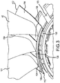
- FIG 3 a perspective view of fan 42 having platform 102 bonded to fan blades 101 is shown, in accordance with various embodiments.
- a root 105 of each fan blade 101 engages walls of fan hub 103 to retain fan blade 101 during rotation.
- Platform 102 comprises a first platform half 104 and a second platform half 106.
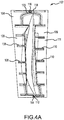
- platform 102 is shown with first platform half 104 and second platform half 106 coupled together to form platform 102.
- First platform half 104 may include stiffening members 108 in the form of ridges formed on bottom surface 109 of first platform half 104.
- Second platform half 106 also includes stiffening members 110 in the form of ridges formed on the bottom surface 111 of second platform half 106.
- the stiffening members may provide rigidity for platform 102.
- First platform half 104 and second platform half 106 may both be made from moldable materials such as a carbon and/or glass reinforced thermoset or thermoplastic. The material may be compression molded using an autoclave or injection molded by injecting material into a mold. The materials may be low cost, low weight materials shaped using low cost techniques. In that regard, platform 102 may reduce the weight and cost of a gas turbine engine.
- Platform 102 may also be coated with an erosion coating (e.g., polyurethane).
- first platform half 104 may have a slot 114 configured to receive one or more hooks.
- Second platform half 106 may include a hook 112 configured to engage slot 114.
- first platform half 104 may also include a receiving member 120 and second platform half 106 may include receiving member 118 with the receiving members configured to receive one or more pins 116.
- pin 116 and hook 112 may serve to attach first platform half 104 to second platform half 106 and form platform 102.
- a ridge formed on a fan blade to radially retain a bonded platform is shown, in accordance with various embodiments.
- a ridge 132 may be formed integrally with fan blade 101.
- Ridge 132 may include a forward segment 136 and an aft segment 134.
- Forward segment 136 may have a greater length than aft segment 134.
- Forward segment may also be tilted at an angle relative to aft segment 134 such that a kink 138 or elbow is formed between the segments.
- Forward segment 136 and aft segment 134 may thus provide retention for platform 102 in an axial direction (forward-to-aft direction).
- first platform half 104 and second platform half 106 of platform 102 may be coupled to fan blade 101 with mounting cavity 140 defined by first platform half 104 following a contour of ridge 132 and fan blade 101.
- mounting cavity 142 is defined by second platform half 106 and may follow a contour of ridge 132 and fan blade 101.
- the mounting cavities mounted over ridge 132 provide resistance to retain platform 102 in the y direction.
- FIG. 5B also further illustrates that stiffening member 108 and stiffening members 110 extend at an angle from bottom surface 109 and bottom surface 111, respectively.
- Seal 141 bonded to a platform 102 is shown, in accordance with various embodiments.
- Seal 141 may be glued, bonded, or otherwise coupled to platform 102 using, for example, a rubber adhesive or epoxy.
- Seal 141 may be made from a fabric-reinforced silicone, for example.
- Seal 141 may include a tab 143 to allow adjacent seals 141 to overlap.
- overlap 144 occurs when an edge of a first seal 141 is allowed to slide into tab 143 of neighboring second seal 141.
- Overlapping seals 141 may extend around a circumference of fan 42 of FIG. 2 to provide sealing between platforms 102.
- a fan blade 101 having a platform 102 bonded to the fan blade 101 is shown, in accordance with various embodiments.
- Platform 102 may be bonded to fan blade 101 by applying an adhesive (e.g., an adhesive paste, epoxy, glue, and/or adhesive film) on the side of bonding member 152 adjacent fan blade 101.
- Platform 102 may be pressed against fan blade 101 with adhesive pressing through indicator openings 150 to indicate that adhesive coverage is good at the location of each indicator opening 150.
- Root 105 of fan blade 101 may extend from platform 102 to allow for installation in fan hub 103, as shown in FIG. 3 .
- Platform 102 is bonded to fan blade 101 and may not rely on other fasteners to fix platform 102 to fan blade 101.
- references to "various embodiments”, “one embodiment”, “an embodiment”, “an example embodiment”, etc. indicate that the embodiment described may include a particular feature, structure, or characteristic, but every embodiment may not necessarily include the particular feature, structure, or characteristic. Moreover, such phrases are not necessarily referring to the same embodiment. Further, when a particular feature, structure, or characteristic is described in connection with an embodiment, it is submitted that it is within the knowledge of one skilled in the art to affect such feature, structure, or characteristic in connection with other embodiments whether or not explicitly described. After reading the description, it will be apparent to one skilled in the relevant art(s) how to implement the disclosure in alternative embodiments.
Landscapes
- Engineering & Computer Science (AREA)
- Mechanical Engineering (AREA)
- General Engineering & Computer Science (AREA)
- Architecture (AREA)
- Structures Of Non-Positive Displacement Pumps (AREA)
Abstract
Description
- The present disclosure relates to gas turbine engines, and, more specifically, to a bonded fan blade flowpath platform.
- Some gas turbine engines include a fan section forward of the turbine section including fan blades. The fan blades may have spacers or platforms between blades at the inner flowpath. Integral metal platforms may add cost and weight to the gas turbine engine. Non-integral platforms secured to a fan hub frequently add weight and a cost to the gas turbine engine. Weight and cost are important considerations in the manufacturing of aircraft engines.
- A fan blade platform is provided. The blade platform may comprise a first platform half comprising a slot at a first end of the first platform half and a first receiving member at a second end of the first platform half opposite the first end of the first platform half. A second platform half may comprise a hook at a first end of the second platform half. The second platform half may also include a second receiving member at a second end of the second platform half opposite the first end of the first platform half with the hook configured to interface with the slot. A pin may be configured to pass through the first receiving member and the second receiving member.
- In various embodiments, the fan blade platform may be made by injection molding or compression molding. The first platform half may have a mounting cavity. A bonding member may extend from the first platform half and have indicator openings. A seal may be bonded to an edge of the first platform half and/or the second platform half. The seal may include a tab configured to overlap with a neighboring seal. The seal may also be a fabric-reinforced silicone. Stiffening members may extend at an angle from a surface of the first platform half.
- A gas turbine engine is also provided and comprises a fan section with a fan blade configured to rotate about an axis. A platform may be bonded to the fan blade using an adhesive paste and/or an adhesive film made from epoxy or other material. The fan blade may comprise a ridge configured to axially and/or radially secure the platform. A mounting member may be defined by the platform and follow a contour of the ridge. Indicator openings may be formed through the platform to indicate adhesive coverage between the platform and the fan blade. The platform may be made by injection molding or compression molding. The platform may comprise a first platform half and a second platform half. A hook may be formed on the first platform half. A slot may be formed on the second platform half and configured to engage the hook. A seal may be bonded to the platform. The platform may be a thermoplastic.
- Also disclosed herein is a fan which comprises a fan blade and a blade platform coupled, for example bonded and mechanically locked, to the fan blade, the blade platform being at least one of a thermoplastic or a thermoset with carbon or fiber glass reinforcement. The Applicant explicitly reserves the right to claim this fan independently in the present application or a divisional application.
- The blade platform may be bonded to the fan blade using an adhesive paste, an epoxy, a glue and/or an adhesive film.
- The foregoing features and elements may be combined in various combinations without exclusivity, unless expressly indicated otherwise. These features and elements as well as the operation thereof will become more apparent in light of the following description and the accompanying drawings. It should be understood, however, the following description and drawings are intended to be exemplary in nature and non-limiting.
- The subject matter of the present disclosure is particularly pointed out and distinctly claimed in the concluding portion of the specification. A more complete understanding of the present disclosure, however, may best be obtained by referring to the detailed description and claims when considered in connection with the figures, wherein like numerals denote like elements.
-
FIG. 1 illustrates an exemplary gas turbine engine, in accordance with various embodiments; -
FIG. 2 illustrates a fan section of a gas turbine engine, in accordance with various embodiments; -
FIG 3 illustrates a fan having a molded platform bonded to the fan blades, in accordance with various embodiments; -
FIG. 4A illustrates a bottom view of a two-piece molded platform for a fan blade, in accordance with various embodiments; -
FIG. 4B illustrates a pin interface to interlock two pieces of a bonded platform, in accordance with various embodiments; -
FIG. 4C illustrates a hook-and-slot interface to interlock two pieces of a bonded platform, in accordance with various embodiments; -
FIG. 5A illustrates a ridge formed on a fan blade to radially retain a bonded platform, in accordance with various embodiments; -
FIG. 5B illustrates a platform coupled to a fan blade and retained axially by a ridge, in accordance with various embodiments; -
FIG. 6A illustrates a seal bonded to a two-piece blade platform, in accordance with various embodiments, -
FIG. 6B illustrates overlap between adjacent seals bonded to adjacent blade platforms, in accordance with various embodiments; -
FIG. 7 illustrates a fan blade having a platform bonded to the fan blade, in accordance with various embodiments. - The detailed description of exemplary embodiments herein makes reference to the accompanying drawings, which show exemplary embodiments by way of illustration. While these exemplary embodiments are described in sufficient detail to enable those skilled in the art to practice the exemplary embodiments of the disclosure, it should be understood that other embodiments may be realized and that logical changes and adaptations in design and construction may be made in accordance with this disclosure and the teachings herein. Thus, the detailed description herein is presented for purposes of illustration only and not limitation. The scope of the disclosure is defined by the appended claims. For example, the steps recited in any of the method or process descriptions may be executed in any order and are not necessarily limited to the order presented.
- Furthermore, any reference to singular includes plural embodiments, and any reference to more than one component or step may include a singular embodiment or step. Also, any reference to attached, fixed, connected or the like may include permanent, removable, temporary, partial, full and/or any other possible attachment option. Additionally, any reference to without contact (or similar phrases) may also include reduced contact or minimal contact. Surface shading lines may be used throughout the figures to denote different parts but not necessarily to denote the same or different materials.
- As used herein, "aft" refers to the direction associated with the tail (e.g., the back end) of an aircraft, or generally, to the direction of exhaust of the gas turbine. As used herein, "forward" refers to the direction associated with the nose (e.g., the front end) of an aircraft, or generally, to the direction of flight or motion.
- As used herein, "distal" refers to the direction radially outward, or generally, away from the axis of rotation of a turbine engine. As used herein, "proximal" refers to a direction radially inward, or generally, towards the axis of rotation of a turbine engine.
- In various embodiments and with reference to
FIG. 1 , a gas-turbine engine 20 is provided. Gas-turbine engine 20 may be a two-spool turbofan that generally incorporates afan section 22, acompressor section 24, acombustor section 26 and aturbine section 28. Alternative engines may include, for example, an augmentor section among other systems or features. In operation,fan section 22 can drive coolant along a bypass flow-path B whilecompressor section 24 can drive coolant along a core flow-path C for compression and communication intocombustor section 26 then expansion throughturbine section 28. Although depicted as a turbofan gas-turbine engine 20 herein, it should be understood that the concepts described herein are not limited to use with turbofans as the teachings may be applied to other types of turbine engines including three-spool architectures. - Gas-
turbine engine 20 may generally comprise alow speed spool 30 and ahigh speed spool 32 mounted for rotation about an engine central longitudinal axis A-A' relative to an enginestatic structure 36 viaseveral bearing systems 38, 38-1, and 38-2. It should be understood that various bearingsystems 38 at various locations may alternatively or additionally be provided, including for example, bearingsystem 38, bearing system 38-1, and bearing system 38-2. -
Low speed spool 30 may generally comprise aninner shaft 40 that interconnects afan 42, a low pressure (or first)compressor section 44 and a low pressure (or first)turbine section 46.Inner shaft 40 may be connected to fan 42 through a gearedarchitecture 48 that can drivefan 42 at a lower speed thanlow speed spool 30.Geared architecture 48 may comprise agear assembly 60 enclosed within agear housing 62.Gear assembly 60 couplesinner shaft 40 to a rotating fan structure.High speed spool 32 may comprise anouter shaft 50 that interconnects a high pressure (or second)compressor 52 and high pressure (or second)turbine 54. Acombustor 56 may be located betweenhigh pressure compressor 52 andhigh pressure turbine 54. Amid-turbine frame 57 of enginestatic structure 36 may be located generally betweenhigh pressure turbine 54 andlow pressure turbine 46.Mid-turbine frame 57 may support one ormore bearing systems 38 inturbine section 28.Inner shaft 40 andouter shaft 50 may be concentric and rotate via bearingsystems 38 about the engine central longitudinal axis A-A', which is collinear with their longitudinal axes. As used herein, a "high pressure" compressor or turbine experiences a higher pressure than a corresponding "low pressure" compressor or turbine. - The core airflow C may be compressed by low
pressure compressor section 44 thenhigh pressure compressor 52, mixed and burned with fuel incombustor 56, then expanded overhigh pressure turbine 54 andlow pressure turbine 46.Mid-turbine frame 57 includesairfoils 59 which are in the core airflow path.Turbines low speed spool 30 andhigh speed spool 32 in response to the expansion. - Gas-
turbine engine 20 may be, for example, a high-bypass ratio geared aircraft engine. In various embodiments, the bypass ratio of gas-turbine engine 20 may be greater than about six (6:1). In various embodiments, the bypass ratio of gas-turbine engine 20 may be greater than ten (10:1). In various embodiments, gearedarchitecture 48 may be an epicyclic gear train, such as a star gear system (sun gear in meshing engagement with a plurality of star gears supported by a carrier and in meshing engagement with a ring gear) or other gear system.Geared architecture 48 may have a gear reduction ratio of greater than about 2.3 (2.3:1) andlow pressure turbine 46 may have a pressure ratio that is greater than about five (5:1). In various embodiments, the bypass ratio of gas-turbine engine 20 is greater than about ten (10:1). In various embodiments, the diameter offan 42 may be significantly larger than that of the lowpressure compressor section 44, and thelow pressure turbine 46 may have a pressure ratio that is greater than about five (5:1).Low pressure turbine 46 pressure ratio may be measured prior to inlet oflow pressure turbine 46 as related to the pressure at the outlet oflow pressure turbine 46 prior to an exhaust nozzle. It should be understood, however, that the above parameters are exemplary of various embodiments of a suitable geared architecture engine and that the present disclosure contemplates other turbine engines including direct drive turbofans. - With reference to
FIG. 2 , afan section 22 of agas turbine engine 20 is shown, in accordance with various embodiments.Fan 42 includes a plurality offan blades 101. Eachfan blade 101 may have aplatform 102 coupled to thefan blade 101 at a proximal location.Platform 102 may form a portion of the proximal wall of core flow-pathC. Fan blades 101 andplatforms 102 may be spaced equally around engine central longitudinal axis A-A'. - With reference to
FIG 3 , a perspective view offan 42 havingplatform 102 bonded tofan blades 101 is shown, in accordance with various embodiments. Aroot 105 of eachfan blade 101 engages walls offan hub 103 to retainfan blade 101 during rotation.Platform 102 comprises afirst platform half 104 and asecond platform half 106. - With reference to
FIGs. 4A through 4C ,platform 102 is shown withfirst platform half 104 andsecond platform half 106 coupled together to formplatform 102.First platform half 104 may include stiffeningmembers 108 in the form of ridges formed onbottom surface 109 offirst platform half 104.Second platform half 106 also includes stiffeningmembers 110 in the form of ridges formed on thebottom surface 111 ofsecond platform half 106. The stiffening members may provide rigidity forplatform 102.First platform half 104 andsecond platform half 106 may both be made from moldable materials such as a carbon and/or glass reinforced thermoset or thermoplastic. The material may be compression molded using an autoclave or injection molded by injecting material into a mold. The materials may be low cost, low weight materials shaped using low cost techniques. In that regard,platform 102 may reduce the weight and cost of a gas turbine engine.Platform 102 may also be coated with an erosion coating (e.g., polyurethane). - In various embodiments,
first platform half 104 may have aslot 114 configured to receive one or more hooks.Second platform half 106 may include ahook 112 configured to engageslot 114. With brief reference toFIG. 4C ,first platform half 104 may also include a receivingmember 120 andsecond platform half 106 may include receivingmember 118 with the receiving members configured to receive one or more pins 116. Whenpin 116 is inserted through an opening defined by the overlap of receivingmember 118 and receivingmember 120,first platform half 104 andsecond platform half 106 may be mechanically coupled. In that regard,pin 116 and hook 112 may serve to attachfirst platform half 104 tosecond platform half 106 andform platform 102. - With reference to
FIGs. 5A and 5B , a ridge formed on a fan blade to radially retain a bonded platform is shown, in accordance with various embodiments. Aridge 132 may be formed integrally withfan blade 101.Ridge 132 may include aforward segment 136 and anaft segment 134.Forward segment 136 may have a greater length thanaft segment 134. Forward segment may also be tilted at an angle relative toaft segment 134 such that akink 138 or elbow is formed between the segments.Forward segment 136 andaft segment 134 may thus provide retention forplatform 102 in an axial direction (forward-to-aft direction). - In various embodiments,
first platform half 104 andsecond platform half 106 ofplatform 102 may be coupled tofan blade 101 with mountingcavity 140 defined byfirst platform half 104 following a contour ofridge 132 andfan blade 101. Similarly, mountingcavity 142 is defined bysecond platform half 106 and may follow a contour ofridge 132 andfan blade 101. The mounting cavities mounted overridge 132 provide resistance to retainplatform 102 in the y direction.FIG. 5B also further illustrates that stiffeningmember 108 and stiffeningmembers 110 extend at an angle frombottom surface 109 andbottom surface 111, respectively. - With reference to
FIGs. 6A and 6B , aseal 141 bonded to aplatform 102 is shown, in accordance with various embodiments.Seal 141 may be glued, bonded, or otherwise coupled toplatform 102 using, for example, a rubber adhesive or epoxy.Seal 141 may be made from a fabric-reinforced silicone, for example.Seal 141 may include atab 143 to allowadjacent seals 141 to overlap. With reference toFIG. 6B , overlap 144 occurs when an edge of afirst seal 141 is allowed to slide intotab 143 of neighboringsecond seal 141. Overlappingseals 141 may extend around a circumference offan 42 ofFIG. 2 to provide sealing betweenplatforms 102. - With reference to
FIG. 7 , afan blade 101 having aplatform 102 bonded to thefan blade 101 is shown, in accordance with various embodiments.Platform 102 may be bonded tofan blade 101 by applying an adhesive (e.g., an adhesive paste, epoxy, glue, and/or adhesive film) on the side ofbonding member 152adjacent fan blade 101.Platform 102 may be pressed againstfan blade 101 with adhesive pressing throughindicator openings 150 to indicate that adhesive coverage is good at the location of eachindicator opening 150.Root 105 offan blade 101 may extend fromplatform 102 to allow for installation infan hub 103, as shown inFIG. 3 .Platform 102 is bonded tofan blade 101 and may not rely on other fasteners to fixplatform 102 tofan blade 101. - Benefits and other advantages have been described herein with regard to specific embodiments. Furthermore, the connecting lines shown in the various figures contained herein are intended to represent exemplary functional relationships and/or physical couplings between the various elements. It should be noted that many alternative or additional functional relationships or physical connections may be present in a practical system. However, the benefits, advantages, and any elements that may cause any benefit or advantage to occur or become more pronounced are not to be construed as critical, required, or essential features or elements of the disclosure. The scope of the disclosure is accordingly to be limited by nothing other than the appended claims, in which reference to an element in the singular is not intended to mean "one and only one" unless explicitly so stated, but rather "one or more." Moreover, where a phrase similar to "at least one of A, B, or C" is used in the claims, it is intended that the phrase be interpreted to mean that A alone may be present in an embodiment, B alone may be present in an embodiment, C alone may be present in an embodiment, or that any combination of the elements A, B and C may be present in a single embodiment; for example, A and B, A and C, B and C, or A and B and C.
- Systems, methods and apparatus are provided herein. In the detailed description herein, references to "various embodiments", "one embodiment", "an embodiment", "an example embodiment", etc., indicate that the embodiment described may include a particular feature, structure, or characteristic, but every embodiment may not necessarily include the particular feature, structure, or characteristic. Moreover, such phrases are not necessarily referring to the same embodiment. Further, when a particular feature, structure, or characteristic is described in connection with an embodiment, it is submitted that it is within the knowledge of one skilled in the art to affect such feature, structure, or characteristic in connection with other embodiments whether or not explicitly described. After reading the description, it will be apparent to one skilled in the relevant art(s) how to implement the disclosure in alternative embodiments.
Claims (15)
- A gas turbine engine (20), comprising:a fan section (22) comprising a fan blade (101) configured to rotate about an axis (A-A');a platform (102) adhesively bonded to the fan blade (101) using at least one of an adhesive paste or an adhesive film.
- The gas turbine engine of claim 1, wherein the fan blade (101) comprises a ridge (132) configured to secure the platform (102) in at least one of an axial direction or a radial direction.
- The gas turbine engine of claim 2, further comprising a mounting member defined by the platform (102) and following a contour of the ridge (132).
- The gas turbine engine of claim 1, 2, or 3, further comprising indicator openings (150) formed through the platform (102) and configured to indicate adhesive coverage between the platform (102) and the fan blade (101).
- The gas turbine engine of any preceding claim, wherein the platform (102) is injection molded or compression molded.
- The gas turbine engine of any preceding claim, wherein the platform (102) comprises a first platform half (104) and a second platform half (106).
- The gas turbine engine of claim 6, further comprising a hook (112) formed on the first platform half (104).
- The gas turbine engine of claim 7, further comprising a slot (114) formed on the second platform half (106) and configured to engage the hook (112).
- The gas turbine engine of any preceding claim, further comprising a seal (141) bonded to the platform (102).
- The gas turbine engine of any preceding claim, wherein the platform (102) comprises at least one of a thermoplastic or a thermoset with carbon or fiber glass reinforcement.
- A fan blade platform (102), comprising:a first platform half (104) comprising a slot (114) at a first end of the first platform half and a first receiving member (120) at a second end of the first platform half (104) opposite the first end of the first platform half (104);a second platform half (106) comprising a hook (112) at a first end of the second platform half (106) and a second receiving member (118) at a second end of the second platform half (106) opposite the first end of the second platform half (106), wherein the hook (112) is configured to interface with the slot (114); anda pin (116) configured to pass through the first receiving member (120) and the second receiving member (118).
- The fan blade platform of claim 11, wherein the fan blade platform (102) is made by injection molding or compression molding.
- The fan blade platform of claim 11 or 12, wherein the first platform half (104) includes a mounting cavity (140).
- The fan blade platform of claim 11, 12 or 13, further comprising a bonding member (152) extending from the first platform half (104), the bonding member (152) including indicator openings (150); and/or
further comprising stiffening members (108) extending from a surface (109) of the first platform half (104). - The fan blade platform of any of claims 11 to 14, further comprising a seal (141) bonded to an edge of the first platform half (104) and/or the second platform half (106), wherein, optionally, the seal (141) comprises a tab (143) configured to overlap with a neighboring seal (141), and/or wherein the seal (141) further comprises a fabric-reinforced silicone.
Applications Claiming Priority (2)
| Application Number | Priority Date | Filing Date | Title |
|---|---|---|---|
| US201462095962P | 2014-12-23 | 2014-12-23 | |
| EP15201383.5A EP3040513B1 (en) | 2014-12-23 | 2015-12-18 | Bonded fan platform |
Related Parent Applications (2)
| Application Number | Title | Priority Date | Filing Date |
|---|---|---|---|
| EP15201383.5A Division EP3040513B1 (en) | 2014-12-23 | 2015-12-18 | Bonded fan platform |
| EP15201383.5A Division-Into EP3040513B1 (en) | 2014-12-23 | 2015-12-18 | Bonded fan platform |
Publications (3)
| Publication Number | Publication Date |
|---|---|
| EP3351727A2 true EP3351727A2 (en) | 2018-07-25 |
| EP3351727A3 EP3351727A3 (en) | 2018-09-12 |
| EP3351727B1 EP3351727B1 (en) | 2020-09-09 |
Family
ID=55024867
Family Applications (2)
| Application Number | Title | Priority Date | Filing Date |
|---|---|---|---|
| EP18155348.8A Active EP3351727B1 (en) | 2014-12-23 | 2015-12-18 | Gas turbine engine |
| EP15201383.5A Active EP3040513B1 (en) | 2014-12-23 | 2015-12-18 | Bonded fan platform |
Family Applications After (1)
| Application Number | Title | Priority Date | Filing Date |
|---|---|---|---|
| EP15201383.5A Active EP3040513B1 (en) | 2014-12-23 | 2015-12-18 | Bonded fan platform |
Country Status (2)
| Country | Link |
|---|---|
| US (1) | US9896949B2 (en) |
| EP (2) | EP3351727B1 (en) |
Families Citing this family (5)
| Publication number | Priority date | Publication date | Assignee | Title |
|---|---|---|---|---|
| US10557350B2 (en) | 2017-03-30 | 2020-02-11 | General Electric Company | I beam blade platform |
| US11242763B2 (en) | 2018-10-22 | 2022-02-08 | General Electric Company | Platform apparatus for propulsion rotor |
| US11015451B1 (en) * | 2019-11-05 | 2021-05-25 | Raytheon Technologies Corporation | Airfoil-mounted platforms of gas turbine engines |
| US11815017B2 (en) | 2020-04-16 | 2023-11-14 | Rtx Corporation | Fan blade platform for gas turbine engine |
| US12000288B2 (en) * | 2021-05-03 | 2024-06-04 | Rtx Corporation | Variable thickness machinable coating for platform seals |
Family Cites Families (8)
| Publication number | Priority date | Publication date | Assignee | Title |
|---|---|---|---|---|
| US4019832A (en) * | 1976-02-27 | 1977-04-26 | General Electric Company | Platform for a turbomachinery blade |
| US5362120A (en) * | 1993-04-05 | 1994-11-08 | Ford Motor Company | Vehicle body construction and method for inspection of adhesively secured joints therein |
| US5820338A (en) | 1997-04-24 | 1998-10-13 | United Technologies Corporation | Fan blade interplatform seal |
| US6217283B1 (en) * | 1999-04-20 | 2001-04-17 | General Electric Company | Composite fan platform |
| US6416280B1 (en) | 2000-11-27 | 2002-07-09 | General Electric Company | One piece spinner |
| FR2914008B1 (en) * | 2007-03-21 | 2009-10-09 | Snecma Sa | ROTARY ASSEMBLY OF A TURBOMACHINE BLOWER |
| US9017033B2 (en) | 2012-06-07 | 2015-04-28 | United Technologies Corporation | Fan blade platform |
| GB201217257D0 (en) * | 2012-09-27 | 2012-11-07 | Rolls Royce Plc | Annulus filler for axial flow machine |
-
2015
- 2015-09-23 US US14/862,390 patent/US9896949B2/en active Active
- 2015-12-18 EP EP18155348.8A patent/EP3351727B1/en active Active
- 2015-12-18 EP EP15201383.5A patent/EP3040513B1/en active Active
Non-Patent Citations (1)
| Title |
|---|
| None |
Also Published As
| Publication number | Publication date |
|---|---|
| EP3040513A3 (en) | 2016-10-12 |
| EP3040513A2 (en) | 2016-07-06 |
| EP3351727A3 (en) | 2018-09-12 |
| EP3040513B1 (en) | 2018-03-14 |
| US20160177754A1 (en) | 2016-06-23 |
| US9896949B2 (en) | 2018-02-20 |
| EP3351727B1 (en) | 2020-09-09 |
Similar Documents
| Publication | Publication Date | Title |
|---|---|---|
| EP3121386B1 (en) | Fan blade platform with stiffening feature, corresponding assembly and method | |
| US9650902B2 (en) | Integral fan blade wear pad and platform seal | |
| EP3351727B1 (en) | Gas turbine engine | |
| EP3252271B1 (en) | Blade assembly, corresponding fan section and gas turbine engine | |
| EP3106289A1 (en) | Co-molded metallic fan case containment ring | |
| EP3489463A1 (en) | Composite fan platform lug reinforcement | |
| EP3026217B1 (en) | Turbine rotor or stator segmented sideplates with anti-rotation | |
| US11002285B2 (en) | Fan blade attachment root with improved strain response | |
| US10465712B2 (en) | Anti-rotation stator vane assembly | |
| US12091991B2 (en) | System for an improved stator assembly | |
| EP3296516B1 (en) | Segmented stator vane | |
| US12352184B2 (en) | Wear pad for root of fan blade | |
| US20150117804A1 (en) | Gas turbine engine bushing |
Legal Events
| Date | Code | Title | Description |
|---|---|---|---|
| PUAI | Public reference made under article 153(3) epc to a published international application that has entered the european phase |
Free format text: ORIGINAL CODE: 0009012 |
|
| STAA | Information on the status of an ep patent application or granted ep patent |
Free format text: STATUS: THE APPLICATION HAS BEEN PUBLISHED |
|
| AC | Divisional application: reference to earlier application |
Ref document number: 3040513 Country of ref document: EP Kind code of ref document: P |
|
| AK | Designated contracting states |
Kind code of ref document: A2 Designated state(s): AL AT BE BG CH CY CZ DE DK EE ES FI FR GB GR HR HU IE IS IT LI LT LU LV MC MK MT NL NO PL PT RO RS SE SI SK SM TR |
|
| PUAL | Search report despatched |
Free format text: ORIGINAL CODE: 0009013 |
|
| AK | Designated contracting states |
Kind code of ref document: A3 Designated state(s): AL AT BE BG CH CY CZ DE DK EE ES FI FR GB GR HR HU IE IS IT LI LT LU LV MC MK MT NL NO PL PT RO RS SE SI SK SM TR |
|
| RIC1 | Information provided on ipc code assigned before grant |
Ipc: F01D 5/14 20060101AFI20180807BHEP Ipc: F01D 5/28 20060101ALI20180807BHEP |
|
| STAA | Information on the status of an ep patent application or granted ep patent |
Free format text: STATUS: REQUEST FOR EXAMINATION WAS MADE |
|
| 17P | Request for examination filed |
Effective date: 20190301 |
|
| RBV | Designated contracting states (corrected) |
Designated state(s): AL AT BE BG CH CY CZ DE DK EE ES FI FR GB GR HR HU IE IS IT LI LT LU LV MC MK MT NL NO PL PT RO RS SE SI SK SM TR |
|
| GRAP | Despatch of communication of intention to grant a patent |
Free format text: ORIGINAL CODE: EPIDOSNIGR1 |
|
| STAA | Information on the status of an ep patent application or granted ep patent |
Free format text: STATUS: GRANT OF PATENT IS INTENDED |
|
| INTG | Intention to grant announced |
Effective date: 20200331 |
|
| GRAS | Grant fee paid |
Free format text: ORIGINAL CODE: EPIDOSNIGR3 |
|
| GRAA | (expected) grant |
Free format text: ORIGINAL CODE: 0009210 |
|
| STAA | Information on the status of an ep patent application or granted ep patent |
Free format text: STATUS: THE PATENT HAS BEEN GRANTED |
|
| AC | Divisional application: reference to earlier application |
Ref document number: 3040513 Country of ref document: EP Kind code of ref document: P |
|
| AK | Designated contracting states |
Kind code of ref document: B1 Designated state(s): AL AT BE BG CH CY CZ DE DK EE ES FI FR GB GR HR HU IE IS IT LI LT LU LV MC MK MT NL NO PL PT RO RS SE SI SK SM TR |
|
| REG | Reference to a national code |
Ref country code: GB Ref legal event code: FG4D |
|
| REG | Reference to a national code |
Ref country code: AT Ref legal event code: REF Ref document number: 1311811 Country of ref document: AT Kind code of ref document: T Effective date: 20200915 Ref country code: CH Ref legal event code: EP |
|
| REG | Reference to a national code |
Ref country code: IE Ref legal event code: FG4D |
|
| REG | Reference to a national code |
Ref country code: DE Ref legal event code: R096 Ref document number: 602015059042 Country of ref document: DE |
|
| REG | Reference to a national code |
Ref country code: LT Ref legal event code: MG4D |
|
| PG25 | Lapsed in a contracting state [announced via postgrant information from national office to epo] |
Ref country code: SE Free format text: LAPSE BECAUSE OF FAILURE TO SUBMIT A TRANSLATION OF THE DESCRIPTION OR TO PAY THE FEE WITHIN THE PRESCRIBED TIME-LIMIT Effective date: 20200909 Ref country code: NO Free format text: LAPSE BECAUSE OF FAILURE TO SUBMIT A TRANSLATION OF THE DESCRIPTION OR TO PAY THE FEE WITHIN THE PRESCRIBED TIME-LIMIT Effective date: 20201209 Ref country code: FI Free format text: LAPSE BECAUSE OF FAILURE TO SUBMIT A TRANSLATION OF THE DESCRIPTION OR TO PAY THE FEE WITHIN THE PRESCRIBED TIME-LIMIT Effective date: 20200909 Ref country code: GR Free format text: LAPSE BECAUSE OF FAILURE TO SUBMIT A TRANSLATION OF THE DESCRIPTION OR TO PAY THE FEE WITHIN THE PRESCRIBED TIME-LIMIT Effective date: 20201210 Ref country code: BG Free format text: LAPSE BECAUSE OF FAILURE TO SUBMIT A TRANSLATION OF THE DESCRIPTION OR TO PAY THE FEE WITHIN THE PRESCRIBED TIME-LIMIT Effective date: 20201209 Ref country code: LT Free format text: LAPSE BECAUSE OF FAILURE TO SUBMIT A TRANSLATION OF THE DESCRIPTION OR TO PAY THE FEE WITHIN THE PRESCRIBED TIME-LIMIT Effective date: 20200909 Ref country code: HR Free format text: LAPSE BECAUSE OF FAILURE TO SUBMIT A TRANSLATION OF THE DESCRIPTION OR TO PAY THE FEE WITHIN THE PRESCRIBED TIME-LIMIT Effective date: 20200909 |
|
| REG | Reference to a national code |
Ref country code: AT Ref legal event code: MK05 Ref document number: 1311811 Country of ref document: AT Kind code of ref document: T Effective date: 20200909 |
|
| REG | Reference to a national code |
Ref country code: NL Ref legal event code: MP Effective date: 20200909 |
|
| PG25 | Lapsed in a contracting state [announced via postgrant information from national office to epo] |
Ref country code: LV Free format text: LAPSE BECAUSE OF FAILURE TO SUBMIT A TRANSLATION OF THE DESCRIPTION OR TO PAY THE FEE WITHIN THE PRESCRIBED TIME-LIMIT Effective date: 20200909 Ref country code: RS Free format text: LAPSE BECAUSE OF FAILURE TO SUBMIT A TRANSLATION OF THE DESCRIPTION OR TO PAY THE FEE WITHIN THE PRESCRIBED TIME-LIMIT Effective date: 20200909 Ref country code: PL Free format text: LAPSE BECAUSE OF FAILURE TO SUBMIT A TRANSLATION OF THE DESCRIPTION OR TO PAY THE FEE WITHIN THE PRESCRIBED TIME-LIMIT Effective date: 20200909 |
|
| RAP2 | Party data changed (patent owner data changed or rights of a patent transferred) |
Owner name: RAYTHEON TECHNOLOGIES CORPORATION |
|
| PG25 | Lapsed in a contracting state [announced via postgrant information from national office to epo] |
Ref country code: SM Free format text: LAPSE BECAUSE OF FAILURE TO SUBMIT A TRANSLATION OF THE DESCRIPTION OR TO PAY THE FEE WITHIN THE PRESCRIBED TIME-LIMIT Effective date: 20200909 Ref country code: CZ Free format text: LAPSE BECAUSE OF FAILURE TO SUBMIT A TRANSLATION OF THE DESCRIPTION OR TO PAY THE FEE WITHIN THE PRESCRIBED TIME-LIMIT Effective date: 20200909 Ref country code: RO Free format text: LAPSE BECAUSE OF FAILURE TO SUBMIT A TRANSLATION OF THE DESCRIPTION OR TO PAY THE FEE WITHIN THE PRESCRIBED TIME-LIMIT Effective date: 20200909 Ref country code: PT Free format text: LAPSE BECAUSE OF FAILURE TO SUBMIT A TRANSLATION OF THE DESCRIPTION OR TO PAY THE FEE WITHIN THE PRESCRIBED TIME-LIMIT Effective date: 20210111 Ref country code: EE Free format text: LAPSE BECAUSE OF FAILURE TO SUBMIT A TRANSLATION OF THE DESCRIPTION OR TO PAY THE FEE WITHIN THE PRESCRIBED TIME-LIMIT Effective date: 20200909 |
|
| PG25 | Lapsed in a contracting state [announced via postgrant information from national office to epo] |
Ref country code: ES Free format text: LAPSE BECAUSE OF FAILURE TO SUBMIT A TRANSLATION OF THE DESCRIPTION OR TO PAY THE FEE WITHIN THE PRESCRIBED TIME-LIMIT Effective date: 20200909 Ref country code: AL Free format text: LAPSE BECAUSE OF FAILURE TO SUBMIT A TRANSLATION OF THE DESCRIPTION OR TO PAY THE FEE WITHIN THE PRESCRIBED TIME-LIMIT Effective date: 20200909 Ref country code: AT Free format text: LAPSE BECAUSE OF FAILURE TO SUBMIT A TRANSLATION OF THE DESCRIPTION OR TO PAY THE FEE WITHIN THE PRESCRIBED TIME-LIMIT Effective date: 20200909 Ref country code: IS Free format text: LAPSE BECAUSE OF FAILURE TO SUBMIT A TRANSLATION OF THE DESCRIPTION OR TO PAY THE FEE WITHIN THE PRESCRIBED TIME-LIMIT Effective date: 20210109 |
|
| REG | Reference to a national code |
Ref country code: DE Ref legal event code: R097 Ref document number: 602015059042 Country of ref document: DE |
|
| PG25 | Lapsed in a contracting state [announced via postgrant information from national office to epo] |
Ref country code: SK Free format text: LAPSE BECAUSE OF FAILURE TO SUBMIT A TRANSLATION OF THE DESCRIPTION OR TO PAY THE FEE WITHIN THE PRESCRIBED TIME-LIMIT Effective date: 20200909 |
|
| PLBE | No opposition filed within time limit |
Free format text: ORIGINAL CODE: 0009261 |
|
| STAA | Information on the status of an ep patent application or granted ep patent |
Free format text: STATUS: NO OPPOSITION FILED WITHIN TIME LIMIT |
|
| REG | Reference to a national code |
Ref country code: CH Ref legal event code: PL |
|
| 26N | No opposition filed |
Effective date: 20210610 |
|
| PG25 | Lapsed in a contracting state [announced via postgrant information from national office to epo] |
Ref country code: DK Free format text: LAPSE BECAUSE OF FAILURE TO SUBMIT A TRANSLATION OF THE DESCRIPTION OR TO PAY THE FEE WITHIN THE PRESCRIBED TIME-LIMIT Effective date: 20200909 Ref country code: SI Free format text: LAPSE BECAUSE OF FAILURE TO SUBMIT A TRANSLATION OF THE DESCRIPTION OR TO PAY THE FEE WITHIN THE PRESCRIBED TIME-LIMIT Effective date: 20200909 Ref country code: MC Free format text: LAPSE BECAUSE OF FAILURE TO SUBMIT A TRANSLATION OF THE DESCRIPTION OR TO PAY THE FEE WITHIN THE PRESCRIBED TIME-LIMIT Effective date: 20200909 |
|
| REG | Reference to a national code |
Ref country code: BE Ref legal event code: MM Effective date: 20201231 |
|
| PG25 | Lapsed in a contracting state [announced via postgrant information from national office to epo] |
Ref country code: IE Free format text: LAPSE BECAUSE OF NON-PAYMENT OF DUE FEES Effective date: 20201218 Ref country code: IT Free format text: LAPSE BECAUSE OF FAILURE TO SUBMIT A TRANSLATION OF THE DESCRIPTION OR TO PAY THE FEE WITHIN THE PRESCRIBED TIME-LIMIT Effective date: 20200909 Ref country code: LU Free format text: LAPSE BECAUSE OF NON-PAYMENT OF DUE FEES Effective date: 20201218 |
|
| PG25 | Lapsed in a contracting state [announced via postgrant information from national office to epo] |
Ref country code: LI Free format text: LAPSE BECAUSE OF NON-PAYMENT OF DUE FEES Effective date: 20201231 Ref country code: CH Free format text: LAPSE BECAUSE OF NON-PAYMENT OF DUE FEES Effective date: 20201231 |
|
| PG25 | Lapsed in a contracting state [announced via postgrant information from national office to epo] |
Ref country code: TR Free format text: LAPSE BECAUSE OF FAILURE TO SUBMIT A TRANSLATION OF THE DESCRIPTION OR TO PAY THE FEE WITHIN THE PRESCRIBED TIME-LIMIT Effective date: 20200909 Ref country code: MT Free format text: LAPSE BECAUSE OF FAILURE TO SUBMIT A TRANSLATION OF THE DESCRIPTION OR TO PAY THE FEE WITHIN THE PRESCRIBED TIME-LIMIT Effective date: 20200909 Ref country code: CY Free format text: LAPSE BECAUSE OF FAILURE TO SUBMIT A TRANSLATION OF THE DESCRIPTION OR TO PAY THE FEE WITHIN THE PRESCRIBED TIME-LIMIT Effective date: 20200909 |
|
| PG25 | Lapsed in a contracting state [announced via postgrant information from national office to epo] |
Ref country code: MK Free format text: LAPSE BECAUSE OF FAILURE TO SUBMIT A TRANSLATION OF THE DESCRIPTION OR TO PAY THE FEE WITHIN THE PRESCRIBED TIME-LIMIT Effective date: 20200909 |
|
| PG25 | Lapsed in a contracting state [announced via postgrant information from national office to epo] |
Ref country code: BE Free format text: LAPSE BECAUSE OF NON-PAYMENT OF DUE FEES Effective date: 20201231 |
|
| P01 | Opt-out of the competence of the unified patent court (upc) registered |
Effective date: 20230520 |
|
| PG25 | Lapsed in a contracting state [announced via postgrant information from national office to epo] |
Ref country code: NL Free format text: LAPSE BECAUSE OF NON-PAYMENT OF DUE FEES Effective date: 20200923 |
|
| REG | Reference to a national code |
Ref country code: DE Ref legal event code: R081 Ref document number: 602015059042 Country of ref document: DE Owner name: RTX CORPORATION (N.D.GES.D. STAATES DELAWARE),, US Free format text: FORMER OWNER: UNITED TECHNOLOGIES CORPORATION, FARMINGTON, CONN., US |
|
| PGFP | Annual fee paid to national office [announced via postgrant information from national office to epo] |
Ref country code: DE Payment date: 20251126 Year of fee payment: 11 |
|
| PGFP | Annual fee paid to national office [announced via postgrant information from national office to epo] |
Ref country code: GB Payment date: 20251119 Year of fee payment: 11 |
|
| PGFP | Annual fee paid to national office [announced via postgrant information from national office to epo] |
Ref country code: FR Payment date: 20251120 Year of fee payment: 11 |