EP3351714A1 - Sensor structure and power window control device using same - Google Patents
Sensor structure and power window control device using same Download PDFInfo
- Publication number
- EP3351714A1 EP3351714A1 EP16846307.3A EP16846307A EP3351714A1 EP 3351714 A1 EP3351714 A1 EP 3351714A1 EP 16846307 A EP16846307 A EP 16846307A EP 3351714 A1 EP3351714 A1 EP 3351714A1
- Authority
- EP
- European Patent Office
- Prior art keywords
- electrode
- detection
- control device
- power window
- sensor structure
- Prior art date
- Legal status (The legal status is an assumption and is not a legal conclusion. Google has not performed a legal analysis and makes no representation as to the accuracy of the status listed.)
- Withdrawn
Links
Images


Classifications
-
- E—FIXED CONSTRUCTIONS
- E05—LOCKS; KEYS; WINDOW OR DOOR FITTINGS; SAFES
- E05F—DEVICES FOR MOVING WINGS INTO OPEN OR CLOSED POSITION; CHECKS FOR WINGS; WING FITTINGS NOT OTHERWISE PROVIDED FOR, CONCERNED WITH THE FUNCTIONING OF THE WING
- E05F15/00—Power-operated mechanisms for wings
- E05F15/40—Safety devices, e.g. detection of obstructions or end positions
- E05F15/42—Detection using safety edges
- E05F15/46—Detection using safety edges responsive to changes in electrical capacitance
-
- B—PERFORMING OPERATIONS; TRANSPORTING
- B60—VEHICLES IN GENERAL
- B60J—WINDOWS, WINDSCREENS, NON-FIXED ROOFS, DOORS, OR SIMILAR DEVICES FOR VEHICLES; REMOVABLE EXTERNAL PROTECTIVE COVERINGS SPECIALLY ADAPTED FOR VEHICLES
- B60J1/00—Windows; Windscreens; Accessories therefor
-
- B—PERFORMING OPERATIONS; TRANSPORTING
- B60—VEHICLES IN GENERAL
- B60J—WINDOWS, WINDSCREENS, NON-FIXED ROOFS, DOORS, OR SIMILAR DEVICES FOR VEHICLES; REMOVABLE EXTERNAL PROTECTIVE COVERINGS SPECIALLY ADAPTED FOR VEHICLES
- B60J1/00—Windows; Windscreens; Accessories therefor
- B60J1/08—Windows; Windscreens; Accessories therefor arranged at vehicle sides
- B60J1/12—Windows; Windscreens; Accessories therefor arranged at vehicle sides adjustable
- B60J1/16—Windows; Windscreens; Accessories therefor arranged at vehicle sides adjustable slidable
- B60J1/17—Windows; Windscreens; Accessories therefor arranged at vehicle sides adjustable slidable vertically
-
- E—FIXED CONSTRUCTIONS
- E05—LOCKS; KEYS; WINDOW OR DOOR FITTINGS; SAFES
- E05F—DEVICES FOR MOVING WINGS INTO OPEN OR CLOSED POSITION; CHECKS FOR WINGS; WING FITTINGS NOT OTHERWISE PROVIDED FOR, CONCERNED WITH THE FUNCTIONING OF THE WING
- E05F15/00—Power-operated mechanisms for wings
- E05F15/60—Power-operated mechanisms for wings using electrical actuators
- E05F15/603—Power-operated mechanisms for wings using electrical actuators using rotary electromotors
- E05F15/665—Power-operated mechanisms for wings using electrical actuators using rotary electromotors for vertically-sliding wings
- E05F15/689—Power-operated mechanisms for wings using electrical actuators using rotary electromotors for vertically-sliding wings specially adapted for vehicle windows
-
- E—FIXED CONSTRUCTIONS
- E05—LOCKS; KEYS; WINDOW OR DOOR FITTINGS; SAFES
- E05F—DEVICES FOR MOVING WINGS INTO OPEN OR CLOSED POSITION; CHECKS FOR WINGS; WING FITTINGS NOT OTHERWISE PROVIDED FOR, CONCERNED WITH THE FUNCTIONING OF THE WING
- E05F15/00—Power-operated mechanisms for wings
- E05F15/60—Power-operated mechanisms for wings using electrical actuators
- E05F15/603—Power-operated mechanisms for wings using electrical actuators using rotary electromotors
- E05F15/665—Power-operated mechanisms for wings using electrical actuators using rotary electromotors for vertically-sliding wings
- E05F15/689—Power-operated mechanisms for wings using electrical actuators using rotary electromotors for vertically-sliding wings specially adapted for vehicle windows
- E05F15/695—Control circuits therefor
-
- G—PHYSICS
- G06—COMPUTING OR CALCULATING; COUNTING
- G06F—ELECTRIC DIGITAL DATA PROCESSING
- G06F3/00—Input arrangements for transferring data to be processed into a form capable of being handled by the computer; Output arrangements for transferring data from processing unit to output unit, e.g. interface arrangements
- G06F3/01—Input arrangements or combined input and output arrangements for interaction between user and computer
- G06F3/03—Arrangements for converting the position or the displacement of a member into a coded form
- G06F3/041—Digitisers, e.g. for touch screens or touch pads, characterised by the transducing means
- G06F3/0416—Control or interface arrangements specially adapted for digitisers
-
- G—PHYSICS
- G06—COMPUTING OR CALCULATING; COUNTING
- G06F—ELECTRIC DIGITAL DATA PROCESSING
- G06F3/00—Input arrangements for transferring data to be processed into a form capable of being handled by the computer; Output arrangements for transferring data from processing unit to output unit, e.g. interface arrangements
- G06F3/01—Input arrangements or combined input and output arrangements for interaction between user and computer
- G06F3/03—Arrangements for converting the position or the displacement of a member into a coded form
- G06F3/041—Digitisers, e.g. for touch screens or touch pads, characterised by the transducing means
- G06F3/044—Digitisers, e.g. for touch screens or touch pads, characterised by the transducing means by capacitive means
-
- G—PHYSICS
- G06—COMPUTING OR CALCULATING; COUNTING
- G06F—ELECTRIC DIGITAL DATA PROCESSING
- G06F3/00—Input arrangements for transferring data to be processed into a form capable of being handled by the computer; Output arrangements for transferring data from processing unit to output unit, e.g. interface arrangements
- G06F3/01—Input arrangements or combined input and output arrangements for interaction between user and computer
- G06F3/03—Arrangements for converting the position or the displacement of a member into a coded form
- G06F3/041—Digitisers, e.g. for touch screens or touch pads, characterised by the transducing means
- G06F3/044—Digitisers, e.g. for touch screens or touch pads, characterised by the transducing means by capacitive means
- G06F3/0444—Digitisers, e.g. for touch screens or touch pads, characterised by the transducing means by capacitive means using a single conductive element covering the whole sensing surface, e.g. by sensing the electrical current flowing at the corners
-
- G—PHYSICS
- G06—COMPUTING OR CALCULATING; COUNTING
- G06F—ELECTRIC DIGITAL DATA PROCESSING
- G06F3/00—Input arrangements for transferring data to be processed into a form capable of being handled by the computer; Output arrangements for transferring data from processing unit to output unit, e.g. interface arrangements
- G06F3/01—Input arrangements or combined input and output arrangements for interaction between user and computer
- G06F3/03—Arrangements for converting the position or the displacement of a member into a coded form
- G06F3/041—Digitisers, e.g. for touch screens or touch pads, characterised by the transducing means
- G06F3/045—Digitisers, e.g. for touch screens or touch pads, characterised by the transducing means using resistive elements, e.g. a single continuous surface or two parallel surfaces put in contact
-
- H—ELECTRICITY
- H03—ELECTRONIC CIRCUITRY
- H03K—PULSE TECHNIQUE
- H03K17/00—Electronic switching or gating, i.e. not by contact-making and –breaking
- H03K17/94—Electronic switching or gating, i.e. not by contact-making and –breaking characterised by the way in which the control signals are generated
- H03K17/96—Touch switches
- H03K17/962—Capacitive touch switches
-
- E—FIXED CONSTRUCTIONS
- E05—LOCKS; KEYS; WINDOW OR DOOR FITTINGS; SAFES
- E05Y—INDEXING SCHEME ASSOCIATED WITH SUBCLASSES E05D AND E05F, RELATING TO CONSTRUCTION ELEMENTS, ELECTRIC CONTROL, POWER SUPPLY, POWER SIGNAL OR TRANSMISSION, USER INTERFACES, MOUNTING OR COUPLING, DETAILS, ACCESSORIES, AUXILIARY OPERATIONS NOT OTHERWISE PROVIDED FOR, APPLICATION THEREOF
- E05Y2400/00—Electronic control; Electrical power; Power supply; Power or signal transmission; User interfaces
- E05Y2400/10—Electronic control
- E05Y2400/44—Sensors not directly associated with the wing movement
- E05Y2400/445—Switches
-
- E—FIXED CONSTRUCTIONS
- E05—LOCKS; KEYS; WINDOW OR DOOR FITTINGS; SAFES
- E05Y—INDEXING SCHEME ASSOCIATED WITH SUBCLASSES E05D AND E05F, RELATING TO CONSTRUCTION ELEMENTS, ELECTRIC CONTROL, POWER SUPPLY, POWER SIGNAL OR TRANSMISSION, USER INTERFACES, MOUNTING OR COUPLING, DETAILS, ACCESSORIES, AUXILIARY OPERATIONS NOT OTHERWISE PROVIDED FOR, APPLICATION THEREOF
- E05Y2400/00—Electronic control; Electrical power; Power supply; Power or signal transmission; User interfaces
- E05Y2400/10—Electronic control
- E05Y2400/52—Safety arrangements associated with the wing motor
- E05Y2400/53—Wing impact prevention or reduction
- E05Y2400/54—Obstruction or resistance detection
-
- E—FIXED CONSTRUCTIONS
- E05—LOCKS; KEYS; WINDOW OR DOOR FITTINGS; SAFES
- E05Y—INDEXING SCHEME ASSOCIATED WITH SUBCLASSES E05D AND E05F, RELATING TO CONSTRUCTION ELEMENTS, ELECTRIC CONTROL, POWER SUPPLY, POWER SIGNAL OR TRANSMISSION, USER INTERFACES, MOUNTING OR COUPLING, DETAILS, ACCESSORIES, AUXILIARY OPERATIONS NOT OTHERWISE PROVIDED FOR, APPLICATION THEREOF
- E05Y2400/00—Electronic control; Electrical power; Power supply; Power or signal transmission; User interfaces
- E05Y2400/80—User interfaces
- E05Y2400/85—User input means
-
- E—FIXED CONSTRUCTIONS
- E05—LOCKS; KEYS; WINDOW OR DOOR FITTINGS; SAFES
- E05Y—INDEXING SCHEME ASSOCIATED WITH SUBCLASSES E05D AND E05F, RELATING TO CONSTRUCTION ELEMENTS, ELECTRIC CONTROL, POWER SUPPLY, POWER SIGNAL OR TRANSMISSION, USER INTERFACES, MOUNTING OR COUPLING, DETAILS, ACCESSORIES, AUXILIARY OPERATIONS NOT OTHERWISE PROVIDED FOR, APPLICATION THEREOF
- E05Y2400/00—Electronic control; Electrical power; Power supply; Power or signal transmission; User interfaces
- E05Y2400/80—User interfaces
- E05Y2400/85—User input means
- E05Y2400/852—Sensors
-
- E—FIXED CONSTRUCTIONS
- E05—LOCKS; KEYS; WINDOW OR DOOR FITTINGS; SAFES
- E05Y—INDEXING SCHEME ASSOCIATED WITH SUBCLASSES E05D AND E05F, RELATING TO CONSTRUCTION ELEMENTS, ELECTRIC CONTROL, POWER SUPPLY, POWER SIGNAL OR TRANSMISSION, USER INTERFACES, MOUNTING OR COUPLING, DETAILS, ACCESSORIES, AUXILIARY OPERATIONS NOT OTHERWISE PROVIDED FOR, APPLICATION THEREOF
- E05Y2400/00—Electronic control; Electrical power; Power supply; Power or signal transmission; User interfaces
- E05Y2400/80—User interfaces
- E05Y2400/85—User input means
- E05Y2400/852—Sensors
- E05Y2400/854—Switches
-
- E—FIXED CONSTRUCTIONS
- E05—LOCKS; KEYS; WINDOW OR DOOR FITTINGS; SAFES
- E05Y—INDEXING SCHEME ASSOCIATED WITH SUBCLASSES E05D AND E05F, RELATING TO CONSTRUCTION ELEMENTS, ELECTRIC CONTROL, POWER SUPPLY, POWER SIGNAL OR TRANSMISSION, USER INTERFACES, MOUNTING OR COUPLING, DETAILS, ACCESSORIES, AUXILIARY OPERATIONS NOT OTHERWISE PROVIDED FOR, APPLICATION THEREOF
- E05Y2900/00—Application of doors, windows, wings or fittings thereof
- E05Y2900/50—Application of doors, windows, wings or fittings thereof for vehicles
- E05Y2900/53—Type of wing
- E05Y2900/55—Windows
-
- H—ELECTRICITY
- H03—ELECTRONIC CIRCUITRY
- H03K—PULSE TECHNIQUE
- H03K2217/00—Indexing scheme related to electronic switching or gating, i.e. not by contact-making or -breaking covered by H03K17/00
- H03K2217/94—Indexing scheme related to electronic switching or gating, i.e. not by contact-making or -breaking covered by H03K17/00 characterised by the way in which the control signal is generated
- H03K2217/96—Touch switches
- H03K2217/9607—Capacitive touch switches
- H03K2217/96071—Capacitive touch switches characterised by the detection principle
- H03K2217/96073—Amplitude comparison
-
- H—ELECTRICITY
- H03—ELECTRONIC CIRCUITRY
- H03K—PULSE TECHNIQUE
- H03K2217/00—Indexing scheme related to electronic switching or gating, i.e. not by contact-making or -breaking covered by H03K17/00
- H03K2217/94—Indexing scheme related to electronic switching or gating, i.e. not by contact-making or -breaking covered by H03K17/00 characterised by the way in which the control signal is generated
- H03K2217/96—Touch switches
- H03K2217/9607—Capacitive touch switches
- H03K2217/960755—Constructional details of capacitive touch and proximity switches
- H03K2217/96078—Sensor being a wire or a strip, e.g. used in automobile door handles or bumpers
Definitions
- the present invention relates to a sensor structure and a power window control device using the sensor structure.
- a power window control device is known that is able to detect, in a non-contact state, a possibility of the trapping of fingers or the like by a window glass (see Patent Document 1, for example).
- This power window control device is a window regulator safety device that controls a window regulator, which raises/lowers the window glass using the rotational force of a motor, and is provided with at least a first electrode arranged on an upper end portion of the window glass and a second electrode arranged on a vehicle body side, electrostatic capacitance measurement means for measuring the electrostatic capacitance between the first electrode and the second electrode, determination means for determining the presence or absence of the possibility of the trapping of fingers or the like on the basis of changes in the electrostatic capacitance measured by the electrostatic capacitance measuring means, and driving means for controlling the rotation of the motor with reference to a determination result of the determination means.
- the power window control device of Patent Document 1 is provided with the detection electrodes for the finger trap detection, and is also provided with a control unit that detects the changes in the electrostatic capacitance of these detection electrodes and controls an opening and closing operation of the power window. This enables the detection of the possibility of the trapping of fingers or the like, and also makes it possible to issue a trap warning on the basis of the detection.
- Patent Document 1 JP 10-110574A
- the detection electrodes for the finger trap detection are arranged on the upper end portion of the window glass and on the vehicle body side, and simply have the finger trap detection function.
- An object of the invention is to provide a sensor structure having two functions, namely, finger trap detection and another detection function, and a power window control device using the sensor structure.
- a sensor structure having two functions, namely, finger trap detection and another detection function, and a power window control device using the sensor structure, can be provided.
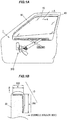
- FIG. 1A is a front view illustrating a configuration of a power window control device according to an embodiment of the invention
- FIG. 1B is a cross-sectional view taken along line A-A in FIG. 1A illustrating a part of a window glass
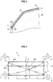
- FIG. 2 is a perspective view illustrating an arrangement, with respect to the window glass, of a detection electrode of the power window control device according to the embodiment of the invention.
- a sensor structure includes a first electrode 100 that detects electrostatic capacitance and a second electrode 200 that detects electrostatic capacitance.
- the first electrode 100 and the second electrode 200 are formed as a bent plate-shaped detection electrode 10, and are configured such that a detection direction for a detection target of the first electrode 100 and a detection direction for a detection target of the second electrode 200 are different directions.
- a power window control device 1 includes the first electrode 100 that is arranged on an upper portion of a window glass 30 of a vehicle and that detects the electrostatic capacitance, and the second electrode 200 that is arranged on a vehicle interior side of the window glass 30 and that detects the electrostatic capacitance.
- the first electrode 100 and the second electrode 200 are formed as the bent plate-shaped detection electrode 10, and are configured such that the detection direction for the detection target of the first electrode 100 and the detection direction for the detection target of the second electrode 200 are different directions.
- the detection electrode 10 is an electrode formed of an electrically conductive material, and an electrostatic capacitance value changes as a result of a finger or the like coming into contact with or coming close to a surface of the detection electrode 10.
- the detection electrode 10 is, for example, mounted on the upper portion or the upper end portion of the window glass 30 of the vehicle, as illustrated in FIG. 1A and FIG. 2 , and detects the contact or approach of the finger or the like.
- the detection electrode 10 includes the first electrode 100 that is arranged on the upper portion of the window glass 30 of the vehicle and that detects the electrostatic capacitance, and the second electrode 200 that is arranged on the vehicle interior side of the window glass 30 and that detects the electrostatic capacitance.
- the first electrode 100 and the second electrode 200 are formed as the bent plate shape.
- a transparent electrode such as indium tin oxide (ITO) can be used as the detection electrode 10.
- the detection electrode 10 is mounted on the upper portion of the window glass 30 of the vehicle and the window glass 30 can be moved up and down inside a window frame 40 by a window regulator 300.
- the detection electrode 10 mounted on the window glass 30 is configured by the first electrode 100 and the second electrode 200.
- the detection direction for the finger or the like that is the detection target is the upward direction (the direction of an arrow B) and for the second electrode 200, the detection direction for the finger or the like that is the detection target is the vehicle interior side (the direction of an arrow C).
- the detection directions for the detection target of the first electrode 100 and the second electrode 200 are set to be different directions.
- the detection electrode 10 enables the trapping of the finger or the like by the window glass 30 and the window frame 40 to be detected using the first electrode 100, while also enabling touch detection or the like from the vehicle interior side (the direction of the arrow C).
- the detection electrode 10 is configured by the first electrode 100 having a width a and the second electrode 200 having a width b.
- the first electrode 100 and the second electrode 200 have a shape that is bent so as to have an L-shaped cross-section.
- the width b of the second electrode 200 is set to be a larger value than that of the width a of the first electrode 100. In this way, a determination in the vicinity of a boundary of the bend can be clearly identified, and further, a touch operation from the vehicle interior side (the direction of the arrow C) can be easily detected.
- FIG. 3 is a developed plan view illustrating the first electrode 100 and the second electrode 200 and illustrating locations at which a voltage (a current) is applied to the detection electrode, a touch point P, and X, Y coordinates.
- the detection electrode 10 has a long shape with respect to the widths a and b, and in FIG. 3 , this length direction is designated as 2c and is illustrated in a scaled down manner.
- an X axis is above a boundary (a bent portion) 150 between the first electrode 100 and the second electrode 200, while a Y axis is at the center in the left to right direction.
- An intersection point of the X axis and the Y axis is an origin O.
- An X coordinate of a right end portion of the first electrode 100 and the second electrode 200 is c, and an X coordinate of a left end portion thereof is - c.
- a Y coordinate of an upper end portion of the first electrode 100 is a
- a Y coordinate of a lower end portion of the second electrode 200 is - b.
- corner portions E1 and E2 in two locations of the first electrode 100, and corner portions E3 and E4 in two locations of the second electrode 200 are electricity supply units at which a voltage is applied to supply a current.
- the first electrode 100 or the second electrode 200 detects the touch position P using a surface-based electrostatic capacitance method.
- the touch position detection using the surface-based electrostatic capacitance method is a method in which an AC current is supplied from the electricity supply units in the four locations of the detection electrode 10 (the first electrode 100 and the second electrode 200), and, using impedance changes between the touch position P and the electricity supply units, touch position coordinates are calculated on the basis of ratios of current values of the four locations. By calculating the touch position coordinates, it is possible to determine which of the first electrode 100 or the second electrode 200 has been touched.
- FIG. 4 is a block diagram illustrating a configuration of the power window control device 1 that uses the sensor structure according to the embodiment of the invention.
- a controller 400 is configured by the electricity supply units that apply the voltage to the corner portions E1 and E2 in the two locations of the first electrode 100, and to the corner portions E3 and E4 in the two locations of the second electrode 200, and respectively supply currents i1, i2, i3, and i4; a coordinate calculation unit that calculates the touch position coordinates on the detection electrode 10 on the basis of the currents i1, i2, i3, and i4; a control signal generation unit that generates control signals S1 and S2 that perform rotational control of a regulator motor 310 of the window regulator 300; and an arithmetic processing unit that controls the above controls in accordance with a predetermined program.
- the controller 400 is, for example, a microcomputer including a central processing unit (CPU) that executes the arithmetic processing in accordance with the program, and a semiconductor memory, such as a RAM, a read only memory (ROM), and the like. Further, the detection electrode 10 is provided with a driver unit for supplying a current to the regulator motor 310, an interface unit that performs the input and output of signals, and the like.
- CPU central processing unit
- ROM read only memory
- the coordinates of the touch position P are calculated on the basis of ratios between the current values (i1, i2, i3, and i4) flowing through the four locations, namely, the corner portions E1 and E2 in the two locations of the first electrode 100 and the corner portions E3 and E4 in the two locations of the second electrode 200.
- X, Y coordinates of the touch position P are calculated using the following type of equation.
- X K 1 + K 2 * i 2 + i 3 / i 1 + i 2 + i 3 + i 4
- Y K 3 + K 4 * i 1 + i 2 / i 1 + i 2 + i 3 + i 4
- K1 and K3 are offset values and K2 and K4 are coefficients.
- the sensor structure can calculate the X, Y coordinates of the touch position P, and in this way, can determine whether the first electrode 100 has been touched or the touch operation has been performed on the second electrode 200. Further, which position with respect to the first electrode 100 and the second electrode 200 has been touched can also be determined, and thus, the sensor structure can perform not only the touch detection, but can also function as a switch input device on the basis of the touch position.
- FIG. 5 is a flowchart illustrating an example of operations performed by the power window control device 1 according to an embodiment of the invention.
- the controller 400 determines whether or not the detection electrode 10 (the first electrode 100 and the second electrode 200) has been touched (Step 1). Since the electrostatic capacitance value changes at the touch position P, the controller 400 can determine the presence or absence of the touch on the basis of whether or not the electrostatic capacitance value has exceeded a predetermined threshold value. When the touch is detected, the operation advances to Step 2, and when the touch is not detected, Step 1 is repeatedly performed.
- the controller 400 determines whether or not, with respect to the Y coordinate of the touch position P, Y > 0 (Step 2).
- Y > 0 applies, the operation advances to Step 3 and when Y > 0 does not apply, the operation advances to Step 5.
- the controller 400 When the Y coordinate of the touch position P is Y > 0, the controller 400 generates a trap signal S1 and outputs the trap signal S1 to the window regulator 300 (Step 3).
- the window regulator 300 can perform rotation control of the regulator motor 310 on the basis of the trap signal S1, using a regulator controller that is not illustrated (Step 4). Specifically, on the basis of the trap signal S1, it is determined that the first electrode 100 has detected trapping of the finger by the window glass 30, and the regulator motor 310 is controlled to rotate in the reverse direction. In this way, even if the window glass 30 is being moved in the upward direction by the window regulator 300, this is reversed and the window glass 30 is caused to move in the downward direction, thus enabling the trapping of the finger or the like to be avoided. Alternatively, the regulator motor 310 need not be controlled to rotate in the reverse direction, and control may be performed so as to stop the rotation thereof.
- the controller 400 When the Y coordinate of the touch position P is not Y > 0, the controller 400 generates an on/off signal S2 and outputs the on/off signal S2 to the window regulator 300 (Step 5).
- the window regulator 300 can perform operation start and stop control of the regulator motor 310 on the basis of the on/off signal S2, using the regulator controller that is not illustrated (Step 6). Specifically, on the basis of the on/off signal S2, when the regulator motor 310 is stopped, the operation thereof can be started, and when the regulator motor 310 is operating, control can be performed to stop the operation thereof. In this way, an operator can start and stop the operation of the power window by performing the touch operation on the second electrode 200 from the interior of the vehicle.
- the first electrode 100 detects the trapping of the finger by the window glass 30. Meanwhile, in addition to the power window operation start and stop switch input described above, various input functions can be assigned to the second electrode 200. As well as detecting the presence or absence of the touch, the detection electrode 10 (the first electrode 100 and the second electrode 200) can calculate the coordinates of the touch position P. Thus, in particular, various functions can be allocated to the second electrode 200, by determining the coordinates of a position that has been touched by the operator from the interior of the vehicle.
- the functions can be allocated in accordance with whether the touch position of the second electrode 200 is at the front, the center or the rear of the window glass 30.
- the operation of the power window is started when the second electrode 200 of the window glass 30 has been touched toward the front, the operation of the power window is stopped when the touch is toward the center, and the power window is caused to rotate in reverse when the touch is toward the rear, and the like.
- the sensor structure and the power window control device 1 according to the present embodiment have the following effects.
Landscapes
- Engineering & Computer Science (AREA)
- General Engineering & Computer Science (AREA)
- Theoretical Computer Science (AREA)
- Human Computer Interaction (AREA)
- Physics & Mathematics (AREA)
- General Physics & Mathematics (AREA)
- Mechanical Engineering (AREA)
- Power-Operated Mechanisms For Wings (AREA)
- Window Of Vehicle (AREA)
Abstract
Description
- The present invention relates to a sensor structure and a power window control device using the sensor structure.
- A power window control device is known that is able to detect, in a non-contact state, a possibility of the trapping of fingers or the like by a window glass (see
Patent Document 1, for example).
This power window control device is a window regulator safety device that controls a window regulator, which raises/lowers the window glass using the rotational force of a motor, and is provided with at least a first electrode arranged on an upper end portion of the window glass and a second electrode arranged on a vehicle body side, electrostatic capacitance measurement means for measuring the electrostatic capacitance between the first electrode and the second electrode, determination means for determining the presence or absence of the possibility of the trapping of fingers or the like on the basis of changes in the electrostatic capacitance measured by the electrostatic capacitance measuring means, and driving means for controlling the rotation of the motor with reference to a determination result of the determination means. - The power window control device of
Patent Document 1 is provided with the detection electrodes for the finger trap detection, and is also provided with a control unit that detects the changes in the electrostatic capacitance of these detection electrodes and controls an opening and closing operation of the power window. This enables the detection of the possibility of the trapping of fingers or the like, and also makes it possible to issue a trap warning on the basis of the detection. - Patent Document 1:
JP 10-110574A - In the power window control device of
Patent Document 1, the detection electrodes for the finger trap detection are arranged on the upper end portion of the window glass and on the vehicle body side, and simply have the finger trap detection function. - An object of the invention is to provide a sensor structure having two functions, namely, finger trap detection and another detection function, and a power window control device using the sensor structure.
-
- [1] A sensor structure according to an aspect of the invention includes: a first electrode that detects electrostatic capacitance; and a second electrode that detects electrostatic capacitance. The first electrode and the second electrode are a detection electrode having a bent plate-shape, and a detection direction for a detection target of the first electrode and a detection direction for a detection target of the second electrode are different directions.
- [2] The sensor structure described in [1] above may be a sensor structure in which a voltage is applied to two locations of corner portions of the first electrode and two locations of corner portions of the second electrode, and a touch position of the first electrode or the second electrode is detected using a surface-based electrostatic capacitance method.
- [3] A power window control device according to another aspect of the invention includes a first electrode that is arranged on an upper portion of a window glass of a vehicle and that detects electrostatic capacitance, and a second electrode arranged on a vehicle interior side of the window glass and that detects electrostatic capacitance. The first electrode and the second electrode are a detection electrode having a bent plate-shape, and a detection direction for a detection target of the first electrode and a detection direction for a detection target of the second electrode are different directions.
- [4] The power window control device described in [3] above may be a power window control device in which a voltage is applied to two locations of corner portions of the first electrode and two locations of corner portions of the second electrode, and a touch position of the first electrode or the second electrode is detected using a surface-based electrostatic capacitance method.
- [5] The power window control device described in [3] or [4] above may be a power window control device in which the first electrode detects trapping of a finger by the window glass, and an opening and closing control of a power window device is performed by the second electrode detecting a touch operation from a vehicle interior side.
- [6] The sensor structure or the power window control device described in any one of [1] to [5] above may be a sensor structure or a power window control device in which the first electrode and the second electrode respectively correspond to a first side surface and a second side surface of a shape obtained by bending a single long plate along a line parallel to a longitudinal direction, and the second side surface has a width larger than the first side surface.
- [7] The sensor structure or the power window control device described in [6] above may be a sensor structure or a power window control device in which the first side surface meets the second side surface at a substantially right angle.
- According to an aspect of the invention, a sensor structure having two functions, namely, finger trap detection and another detection function, and a power window control device using the sensor structure, can be provided.
-
-
FIG. 1A is a front view illustrating a configuration of a power window control device according to an embodiment of the invention. -
FIG. 1B is a cross-sectional view taken along line A-A ofFIG. 1A illustrating a part of a window glass. -
FIG. 2 is a perspective view illustrating an arrangement, with respect to a window glass, of a detection electrode of a power window control device according to an embodiment of the invention. -
FIG. 3 is a developed plan view illustrating afirst electrode 100 and asecond electrode 200 and illustrating locations at which a voltage (a current) is applied to the detection electrode, a touch point P, and X, Y coordinates. -
FIG. 4 is a block diagram illustrating the configuration of a power window control device using a sensor structure according to an embodiment of the invention. -
FIG. 5 is a flowchart illustrating an example of operations performed by a power window control device according to an embodiment of the invention. -
FIG. 1A is a front view illustrating a configuration of a power window control device according to an embodiment of the invention, andFIG. 1B is a cross-sectional view taken along line A-A inFIG. 1A illustrating a part of a window glass. Further,FIG. 2 is a perspective view illustrating an arrangement, with respect to the window glass, of a detection electrode of the power window control device according to the embodiment of the invention. - A sensor structure according to the present embodiment includes a
first electrode 100 that detects electrostatic capacitance and asecond electrode 200 that detects electrostatic capacitance. Thefirst electrode 100 and thesecond electrode 200 are formed as a bent plate-shaped detection electrode 10, and are configured such that a detection direction for a detection target of thefirst electrode 100 and a detection direction for a detection target of thesecond electrode 200 are different directions. - Further, a power
window control device 1 according to the present embodiment includes thefirst electrode 100 that is arranged on an upper portion of awindow glass 30 of a vehicle and that detects the electrostatic capacitance, and thesecond electrode 200 that is arranged on a vehicle interior side of thewindow glass 30 and that detects the electrostatic capacitance. Thefirst electrode 100 and thesecond electrode 200 are formed as the bent plate-shaped detection electrode 10, and are configured such that the detection direction for the detection target of thefirst electrode 100 and the detection direction for the detection target of thesecond electrode 200 are different directions. - The
detection electrode 10 is an electrode formed of an electrically conductive material, and an electrostatic capacitance value changes as a result of a finger or the like coming into contact with or coming close to a surface of thedetection electrode 10. - The
detection electrode 10 is, for example, mounted on the upper portion or the upper end portion of thewindow glass 30 of the vehicle, as illustrated inFIG. 1A andFIG. 2 , and detects the contact or approach of the finger or the like. - The
detection electrode 10 includes thefirst electrode 100 that is arranged on the upper portion of thewindow glass 30 of the vehicle and that detects the electrostatic capacitance, and thesecond electrode 200 that is arranged on the vehicle interior side of thewindow glass 30 and that detects the electrostatic capacitance. Thefirst electrode 100 and thesecond electrode 200 are formed as the bent plate shape. In addition to an electrically conductive material, such as copper, a transparent electrode, such as indium tin oxide (ITO), can be used as thedetection electrode 10. - As illustrated in
FIG. 1A , thedetection electrode 10 is mounted on the upper portion of thewindow glass 30 of the vehicle and thewindow glass 30 can be moved up and down inside awindow frame 40 by awindow regulator 300. As illustrated inFIG. 1B , thedetection electrode 10 mounted on thewindow glass 30 is configured by thefirst electrode 100 and thesecond electrode 200. For thefirst electrode 100, the detection direction for the finger or the like that is the detection target is the upward direction (the direction of an arrow B) and for thesecond electrode 200, the detection direction for the finger or the like that is the detection target is the vehicle interior side (the direction of an arrow C). In other words, the detection directions for the detection target of thefirst electrode 100 and thesecond electrode 200 are set to be different directions. In this way, for example, thedetection electrode 10 enables the trapping of the finger or the like by thewindow glass 30 and thewindow frame 40 to be detected using thefirst electrode 100, while also enabling touch detection or the like from the vehicle interior side (the direction of the arrow C). - As illustrated in
FIG. 1B andFIG. 2 , thedetection electrode 10 is configured by thefirst electrode 100 having a width a and thesecond electrode 200 having a width b. As illustrated inFIG. 1B , thefirst electrode 100 and thesecond electrode 200 have a shape that is bent so as to have an L-shaped cross-section. Further, the width b of thesecond electrode 200 is set to be a larger value than that of the width a of thefirst electrode 100. In this way, a determination in the vicinity of a boundary of the bend can be clearly identified, and further, a touch operation from the vehicle interior side (the direction of the arrow C) can be easily detected. -
FIG. 3 is a developed plan view illustrating thefirst electrode 100 and thesecond electrode 200 and illustrating locations at which a voltage (a current) is applied to the detection electrode, a touch point P, and X, Y coordinates. As illustrated inFIG. 1A andFIG. 2 , thedetection electrode 10 has a long shape with respect to the widths a and b, and inFIG. 3 , this length direction is designated as 2c and is illustrated in a scaled down manner. - In
FIG. 3 , an X axis is above a boundary (a bent portion) 150 between thefirst electrode 100 and thesecond electrode 200, while a Y axis is at the center in the left to right direction. An intersection point of the X axis and the Y axis is an origin O. An X coordinate of a right end portion of thefirst electrode 100 and thesecond electrode 200 is c, and an X coordinate of a left end portion thereof is - c. A Y coordinate of an upper end portion of thefirst electrode 100 is a, and a Y coordinate of a lower end portion of thesecond electrode 200 is - b. - Further, in
FIG. 3 , corner portions E1 and E2 in two locations of thefirst electrode 100, and corner portions E3 and E4 in two locations of thesecond electrode 200 are electricity supply units at which a voltage is applied to supply a current. - In the sensor structure according to the present embodiment, the
first electrode 100 or thesecond electrode 200 detects the touch position P using a surface-based electrostatic capacitance method. The touch position detection using the surface-based electrostatic capacitance method is a method in which an AC current is supplied from the electricity supply units in the four locations of the detection electrode 10 (thefirst electrode 100 and the second electrode 200), and, using impedance changes between the touch position P and the electricity supply units, touch position coordinates are calculated on the basis of ratios of current values of the four locations. By calculating the touch position coordinates, it is possible to determine which of thefirst electrode 100 or thesecond electrode 200 has been touched. -
FIG. 4 is a block diagram illustrating a configuration of the powerwindow control device 1 that uses the sensor structure according to the embodiment of the invention. - A
controller 400 is configured by the electricity supply units that apply the voltage to the corner portions E1 and E2 in the two locations of thefirst electrode 100, and to the corner portions E3 and E4 in the two locations of thesecond electrode 200, and respectively supply currents i1, i2, i3, and i4; a coordinate calculation unit that calculates the touch position coordinates on thedetection electrode 10 on the basis of the currents i1, i2, i3, and i4; a control signal generation unit that generates control signals S1 and S2 that perform rotational control of aregulator motor 310 of thewindow regulator 300; and an arithmetic processing unit that controls the above controls in accordance with a predetermined program. - The
controller 400 is, for example, a microcomputer including a central processing unit (CPU) that executes the arithmetic processing in accordance with the program, and a semiconductor memory, such as a RAM, a read only memory (ROM), and the like. Further, thedetection electrode 10 is provided with a driver unit for supplying a current to theregulator motor 310, an interface unit that performs the input and output of signals, and the like. - In the detection of the touch position P using the surface-based electrostatic capacitance method, the coordinates of the touch position P are calculated on the basis of ratios between the current values (i1, i2, i3, and i4) flowing through the four locations, namely, the corner portions E1 and E2 in the two locations of the
first electrode 100 and the corner portions E3 and E4 in the two locations of thesecond electrode 200. - In
FIG. 3 , X, Y coordinates of the touch position P are calculated using the following type of equation.

- Here, when K1 = 0, K2 = c, K3 = a, and K4 = - a - b, as illustrated in
FIG. 3 , with respect to a region of thefirst electrode 100 of thedetection electrode 10, the coordinates of the upper end portion are (0, a), the coordinates of the lower end portion are (0, - b), the coordinates of the right end portion are (c, 0), and the coordinates of the left end portion are (-c, 0). - Specifically,


first electrode 100 and the corner portions E3 and E4 in the two locations of thesecond electrode 200, the X, Y coordinates of the touch position P can be calculated in thecontroller 400 using the above-described equations. - Using the above-described equations, the sensor structure according to an embodiment of the invention can calculate the X, Y coordinates of the touch position P, and in this way, can determine whether the
first electrode 100 has been touched or the touch operation has been performed on thesecond electrode 200. Further, which position with respect to thefirst electrode 100 and thesecond electrode 200 has been touched can also be determined, and thus, the sensor structure can perform not only the touch detection, but can also function as a switch input device on the basis of the touch position. -
FIG. 5 is a flowchart illustrating an example of operations performed by the powerwindow control device 1 according to an embodiment of the invention. - The
controller 400 determines whether or not the detection electrode 10 (thefirst electrode 100 and the second electrode 200) has been touched (Step 1). Since the electrostatic capacitance value changes at the touch position P, thecontroller 400 can determine the presence or absence of the touch on the basis of whether or not the electrostatic capacitance value has exceeded a predetermined threshold value. When the touch is detected, the operation advances toStep 2, and when the touch is not detected,Step 1 is repeatedly performed. - The
controller 400 determines whether or not, with respect to the Y coordinate of the touch position P, Y > 0 (Step 2). Thecontroller 400 calculates the Y coordinate using the equations:

Step 3, and when Y > 0 does not apply, the operation advances toStep 5. - When the Y coordinate of the touch position P is Y > 0, the
controller 400 generates a trap signal S1 and outputs the trap signal S1 to the window regulator 300 (Step 3). - The
window regulator 300 can perform rotation control of theregulator motor 310 on the basis of the trap signal S1, using a regulator controller that is not illustrated (Step 4). Specifically, on the basis of the trap signal S1, it is determined that thefirst electrode 100 has detected trapping of the finger by thewindow glass 30, and theregulator motor 310 is controlled to rotate in the reverse direction. In this way, even if thewindow glass 30 is being moved in the upward direction by thewindow regulator 300, this is reversed and thewindow glass 30 is caused to move in the downward direction, thus enabling the trapping of the finger or the like to be avoided. Alternatively, theregulator motor 310 need not be controlled to rotate in the reverse direction, and control may be performed so as to stop the rotation thereof. - When the Y coordinate of the touch position P is not Y > 0, the
controller 400 generates an on/off signal S2 and outputs the on/off signal S2 to the window regulator 300 (Step 5). - The
window regulator 300 can perform operation start and stop control of theregulator motor 310 on the basis of the on/off signal S2, using the regulator controller that is not illustrated (Step 6). Specifically, on the basis of the on/off signal S2, when theregulator motor 310 is stopped, the operation thereof can be started, and when theregulator motor 310 is operating, control can be performed to stop the operation thereof. In this way, an operator can start and stop the operation of the power window by performing the touch operation on thesecond electrode 200 from the interior of the vehicle. - Through the flow of the above-described series of operations, the control of the
window regulator 300 ends. Note that the flow of this series of operations can be set to be repeated as necessary. - As described above, the
first electrode 100 detects the trapping of the finger by thewindow glass 30. Meanwhile, in addition to the power window operation start and stop switch input described above, various input functions can be assigned to thesecond electrode 200. As well as detecting the presence or absence of the touch, the detection electrode 10 (thefirst electrode 100 and the second electrode 200) can calculate the coordinates of the touch position P. Thus, in particular, various functions can be allocated to thesecond electrode 200, by determining the coordinates of a position that has been touched by the operator from the interior of the vehicle. - For example, the functions can be allocated in accordance with whether the touch position of the
second electrode 200 is at the front, the center or the rear of thewindow glass 30. For example, the operation of the power window is started when thesecond electrode 200 of thewindow glass 30 has been touched toward the front, the operation of the power window is stopped when the touch is toward the center, and the power window is caused to rotate in reverse when the touch is toward the rear, and the like. - The sensor structure and the power
window control device 1 according to the present embodiment have the following effects. - (1) In the sensor structure according to the present embodiment, the
first electrode 100 or thesecond electrode 200 detects the touch position P using the surface-based electrostatic capacitance method. The touch position detection using the surface-based electrostatic capacitance method is a method in which the AC current is supplied from the electricity supply units at the four locations of the detection electrode 10 (thefirst electrode 100 and the second electrode 200), and the touch position coordinates are calculated on the basis of the ratios of the current values of the four locations, using impedance changes between the touch position P and the electricity supply units. As a result, as well as being able to detect the presence or absence of the touch, by calculating the touch position coordinates, it is possible to determine which of thefirst electrode 100 or thesecond electrode 200 has been touched. - (2) In the power
window control device 1 that uses the above-described sensor structure, as well as being able to perform the reverse operation control and the stop control of thewindow regulator 300 using the touch detection of thefirst electrode 100, by detecting the touch operation by the operator on thesecond electrode 200 from the interior of the vehicle, the start and stop operation of the power window can also be performed. - (3) In this way, the sensor structure having the two functions of the finger trap detection and the other function, and the power
window control device 1 that uses this sensor structure, can be provided. - (4) Using the above-described equations, the sensor structure according to an embodiment of the invention can calculate the X, Y coordinates of the touch position P, and thus can go so far as to determine on which position, on the
first electrode 100 or thesecond electrode 200, the touch operation has been performed. Thus, the sensor structure can also function as the switch input device on the basis of the touch position. - Although several embodiments of the invention have been described above, these embodiments are merely examples and the invention according to the claims is not to be limited thereto. These novel embodiments may be implemented in various other forms, and various omissions, substitutions, changes, and the like can be made without departing from the spirit and scope of the invention. In addition, all the combinations of the features described in these embodiments are not necessarily needed to solve the technical problem. Further, these embodiments are included within the spirit and scope of the invention and also within the invention described in the claims and the scope of equivalents thereof. Reference signs list
-
- 1 Power window control device
- 10 Detection electrode
- 30 Window glass
- 40 Window frame
- 100 First electrode
- 200 Second electrode
Claims (9)
- A sensor structure, comprising:a first electrode configured to detect electrostatic capacitance; anda second electrode configured to detect electrostatic capacitance,wherein the first electrode and the second electrode are arranged to provide a detection electrode having a bent plate-shape, andwherein a detection direction for a detection target of the first electrode and a detection direction for a detection target of the second electrode are different directions.
- The sensor structure according to claim 1, wherein a voltage is applied to corner portions in two locations of the first electrode and corner portions in two locations of the second electrode, and
wherein a touch position of one of the first electrode and the second electrode is detected by surface capacitive type sensing. - A power window control device, comprising:a first electrode arranged on an upper portion of a window glass of a vehicle and configured to detect electrostatic capacitance; anda second electrode arranged on a vehicle interior side of the window glass and configured to detect electrostatic capacitance,wherein the first electrode and the second electrode are arranged to provide a detection electrode having a bent plate-shape, andwherein a detection direction for a detection target of the first electrode and a detection direction for a detection target of the second electrode are different directions.
- The power window control device according to claim 3, wherein a voltage is applied to corner portions in two locations of the first electrode and corner portions in two locations of the second electrode, and
wherein a touch position of one of the first electrode and the second electrode is detected by surface capacitive type sensing. - The power window control device according to claim 3 or 4, wherein the first electrode detects trapping of a finger by the window glass, and an opening and closing control of a power window device is performed by the second electrode detecting a touch operation from an interior side of the vehicle.
- The sensor structure according to claim 1 or 2, wherein the first electrode and the second electrode respectively correspond to a first side surface and a second side surface of a shape obtained by bending a single long plate along a line parallel to a longitudinal direction, and
wherein the second side surface has a width larger than the first side surface. - The power window control device according to any one of claims 3 to 5, wherein the first electrode and the second electrode respectively correspond to a first side surface and a second side surface of a shape obtained by bending a single long plate along a line parallel to a longitudinal direction, and
wherein the second side surface has a width larger than the first side surface. - The sensor structure according to claim 6, wherein the first side surface meets the second side surface at a substantially right angle.
- The power window control device according to claim 7, wherein the first side surface meets the second side surface at a substantially right angle.
Applications Claiming Priority (2)
| Application Number | Priority Date | Filing Date | Title |
|---|---|---|---|
| JP2015182493A JP6489983B2 (en) | 2015-09-16 | 2015-09-16 | Sensor structure and power window control device using the same |
| PCT/JP2016/076091 WO2017047436A1 (en) | 2015-09-16 | 2016-09-06 | Sensor structure and power window control device using same |
Publications (2)
| Publication Number | Publication Date |
|---|---|
| EP3351714A1 true EP3351714A1 (en) | 2018-07-25 |
| EP3351714A4 EP3351714A4 (en) | 2019-04-24 |
Family
ID=58289230
Family Applications (1)
| Application Number | Title | Priority Date | Filing Date |
|---|---|---|---|
| EP16846307.3A Withdrawn EP3351714A4 (en) | 2015-09-16 | 2016-09-06 | SENSOR STRUCTURE AND POWER WINDOW CONTROL DEVICE WITH IT |
Country Status (4)
| Country | Link |
|---|---|
| US (1) | US20180258681A1 (en) |
| EP (1) | EP3351714A4 (en) |
| JP (1) | JP6489983B2 (en) |
| WO (1) | WO2017047436A1 (en) |
Families Citing this family (5)
| Publication number | Priority date | Publication date | Assignee | Title |
|---|---|---|---|---|
| JP2017025580A (en) * | 2015-07-22 | 2017-02-02 | 株式会社東海理化電機製作所 | Opening/closing control device |
| US11225195B2 (en) | 2019-01-28 | 2022-01-18 | AISIN Technical Center of America, Inc. | Occupant step with kick sensor |
| DE102019212015A1 (en) * | 2019-08-09 | 2021-02-11 | Brose Fahrzeugteile Se & Co. Kommanditgesellschaft, Bamberg | Assembly device of a window regulator |
| CN110847748B (en) * | 2019-12-02 | 2021-06-15 | 温州广信电机有限公司 | Single-arm type four-connecting-rod glass lifter for automobile |
| CN115263112B (en) * | 2022-07-12 | 2024-02-23 | 武汉理工大学 | A method and system for generating simulated Hall signals for the anti-pinch module of a glass lifter |
Family Cites Families (19)
| Publication number | Priority date | Publication date | Assignee | Title |
|---|---|---|---|---|
| DE3111696A1 (en) * | 1981-03-25 | 1982-10-07 | FHN-Verbindungstechnik GmbH, 8501 Eckental | "GLASS PANEL FOR A MOTOR OPERATED RETRACTABLE VEHICLE WINDOW, WITH A SAFETY CONTROL CIRCUIT CONTROLLING TOUCH SENSOR ON ITS UPPER EDGE" |
| JPS6042879U (en) * | 1983-09-01 | 1985-03-26 | 木下 邦男 | Accident prevention device using power windows |
| DE3513051A1 (en) * | 1985-04-12 | 1986-10-23 | FHN-Verbindungstechnik GmbH, 8501 Eckental | Motor-actuated car window with a jamming safeguard |
| US6782759B2 (en) * | 2001-07-09 | 2004-08-31 | Nartron Corporation | Anti-entrapment system |
| DE102005005185B4 (en) * | 2005-02-03 | 2007-04-12 | Daimlerchrysler Ag | Switching arrangement for a switching element for opening and closing a vehicle wing |
| US7552230B2 (en) * | 2005-06-15 | 2009-06-23 | International Business Machines Corporation | Method and apparatus for reducing spam on peer-to-peer networks |
| JP2007137091A (en) * | 2005-11-14 | 2007-06-07 | Nippon Sheet Glass Co Ltd | Window glass, window glass electrode lead-out device, window glass conductivity-adding method, and a window glass electrode lead-out method |
| GB2435517A (en) * | 2006-02-17 | 2007-08-29 | Gdx North America Inc | Vehicle opening sensor device |
| JP5081403B2 (en) * | 2006-06-19 | 2012-11-28 | トヨタ自動車株式会社 | Opening and closing body moving device and abnormality detection system |
| JP5128849B2 (en) * | 2007-05-24 | 2013-01-23 | シロキ工業株式会社 | Power window and window glass |
| US20080302014A1 (en) * | 2007-06-05 | 2008-12-11 | Gm Global Technology Operations, Inc. | Method and apparatus for positioning a motor actuated vehicle accessory |
| JP5214938B2 (en) * | 2007-09-26 | 2013-06-19 | シロキ工業株式会社 | Power door |
| WO2011024306A1 (en) * | 2009-08-31 | 2011-03-03 | Nonogaki Keiichi | Electrostatic capacity type proximity sensor |
| JP2011252881A (en) * | 2010-06-04 | 2011-12-15 | Alps Electric Co Ltd | Sensor module and moving opening/closing body |
| EP2948825A4 (en) * | 2013-01-23 | 2016-09-14 | Nokia Technologies Oy | METHOD AND APPARATUS FOR LIMITING A DETECTION REGION OF A CAPACITIVE DETECTION ELECTRODE |
| JP5937705B1 (en) * | 2015-01-15 | 2016-06-22 | 株式会社城南製作所 | Door glass opening and closing device for vehicles |
| JP2017020174A (en) * | 2015-07-07 | 2017-01-26 | 株式会社東海理化電機製作所 | Pinching detection sensor |
| JP2017048614A (en) * | 2015-09-02 | 2017-03-09 | 株式会社東海理化電機製作所 | Entrapment detecting sensor and open/close body control device |
| AT519601A1 (en) * | 2017-02-14 | 2018-08-15 | Liberda Viktor | METHOD AND DEVICE FOR CONTROLLING A DOOR, PREFERABLY SLIDING DOOR |
-
2015
- 2015-09-16 JP JP2015182493A patent/JP6489983B2/en not_active Expired - Fee Related
-
2016
- 2016-09-06 EP EP16846307.3A patent/EP3351714A4/en not_active Withdrawn
- 2016-09-06 WO PCT/JP2016/076091 patent/WO2017047436A1/en not_active Ceased
- 2016-09-06 US US15/759,632 patent/US20180258681A1/en not_active Abandoned
Also Published As
| Publication number | Publication date |
|---|---|
| JP2017057612A (en) | 2017-03-23 |
| WO2017047436A1 (en) | 2017-03-23 |
| US20180258681A1 (en) | 2018-09-13 |
| JP6489983B2 (en) | 2019-03-27 |
| EP3351714A4 (en) | 2019-04-24 |
Similar Documents
| Publication | Publication Date | Title |
|---|---|---|
| US20180258681A1 (en) | Sensor structure and power window control device using same | |
| US9983745B2 (en) | Touch sensor device and controller | |
| EP2786902A1 (en) | Vehicle operating device | |
| JP6532128B2 (en) | Operation detection device | |
| JP6284391B2 (en) | Capacitive input device | |
| CN105278784A (en) | touch input device | |
| CN104020900A (en) | Input operation receiving apparatus and threshold value adjusting method | |
| EP3690913B1 (en) | Operation input device and door handle | |
| KR102114964B1 (en) | Touch Screen Panel | |
| US20140340356A1 (en) | Input device | |
| US10551982B2 (en) | Instruction reception apparatus, information processing apparatus, signal processing method, and program | |
| JP2016004632A (en) | Touch switch | |
| JP6661309B2 (en) | Touch panel device | |
| JP6350310B2 (en) | Operating device | |
| JP6038547B2 (en) | Operation input device | |
| WO2014002315A1 (en) | Operation device | |
| KR101776601B1 (en) | Estimating method for intensity of pressure based on area of touched region and touch input apparatus for sensing intensity of pressure based on area of touched region | |
| US20200241694A1 (en) | Proximity detection device and proximity detection method | |
| CN113677950A (en) | Electrostatic capacitance detection sensor | |
| CN112334868A (en) | Capacitive sensor system for contact recognition | |
| JP5914419B2 (en) | Input device, electronic equipment | |
| JP7277392B2 (en) | Remote controllers, processors and computer programs | |
| JP2015133044A (en) | Manipulation input device | |
| CN112513796A (en) | Touch panel detection method and touch panel | |
| JP2017083986A (en) | Operation input device |
Legal Events
| Date | Code | Title | Description |
|---|---|---|---|
| PUAI | Public reference made under article 153(3) epc to a published international application that has entered the european phase |
Free format text: ORIGINAL CODE: 0009012 |
|
| 17P | Request for examination filed |
Effective date: 20180308 |
|
| AK | Designated contracting states |
Kind code of ref document: A1 Designated state(s): AL AT BE BG CH CY CZ DE DK EE ES FI FR GB GR HR HU IE IS IT LI LT LU LV MC MK MT NL NO PL PT RO RS SE SI SK SM TR |
|
| AX | Request for extension of the european patent |
Extension state: BA ME |
|
| DAV | Request for validation of the european patent (deleted) | ||
| DAX | Request for extension of the european patent (deleted) | ||
| A4 | Supplementary search report drawn up and despatched |
Effective date: 20190321 |
|
| RIC1 | Information provided on ipc code assigned before grant |
Ipc: E05F 15/695 20150101ALI20190315BHEP Ipc: H03K 17/96 20060101ALI20190315BHEP Ipc: G06F 3/045 20060101ALI20190315BHEP Ipc: B60J 1/00 20060101ALI20190315BHEP Ipc: B60J 1/17 20060101ALI20190315BHEP Ipc: G06F 3/044 20060101ALI20190315BHEP Ipc: E05F 15/689 20150101ALI20190315BHEP Ipc: E05F 15/46 20150101AFI20190315BHEP |
|
| STAA | Information on the status of an ep patent application or granted ep patent |
Free format text: STATUS: THE APPLICATION HAS BEEN WITHDRAWN |
|
| 18W | Application withdrawn |
Effective date: 20190909 |