EP3351357A1 - Razor system - Google Patents
Razor system Download PDFInfo
- Publication number
- EP3351357A1 EP3351357A1 EP17152934.0A EP17152934A EP3351357A1 EP 3351357 A1 EP3351357 A1 EP 3351357A1 EP 17152934 A EP17152934 A EP 17152934A EP 3351357 A1 EP3351357 A1 EP 3351357A1
- Authority
- EP
- European Patent Office
- Prior art keywords
- cartridge
- protector
- handle
- wall
- housing
- Prior art date
- Legal status (The legal status is an assumption and is not a legal conclusion. Google has not performed a legal analysis and makes no representation as to the accuracy of the status listed.)
- Withdrawn
Links
- 230000001012 protector Effects 0.000 claims abstract description 74
- 230000002633 protecting effect Effects 0.000 claims abstract description 3
- 238000000034 method Methods 0.000 claims description 9
- 230000001154 acute effect Effects 0.000 claims description 5
- 230000035939 shock Effects 0.000 description 4
- 230000007246 mechanism Effects 0.000 description 3
- 230000006870 function Effects 0.000 description 2
- 239000000463 material Substances 0.000 description 2
- 238000013459 approach Methods 0.000 description 1
- 230000005540 biological transmission Effects 0.000 description 1
- 230000008859 change Effects 0.000 description 1
- 230000000295 complement effect Effects 0.000 description 1
- 239000000428 dust Substances 0.000 description 1
- 230000002401 inhibitory effect Effects 0.000 description 1
- 230000009993 protective function Effects 0.000 description 1
- 230000002787 reinforcement Effects 0.000 description 1
Images



Classifications
-
- B—PERFORMING OPERATIONS; TRANSPORTING
- B26—HAND CUTTING TOOLS; CUTTING; SEVERING
- B26B—HAND-HELD CUTTING TOOLS NOT OTHERWISE PROVIDED FOR
- B26B21/00—Razors of the open or knife type; Safety razors or other shaving implements of the planing type; Hair-trimming devices involving a razor-blade; Equipment therefor
- B26B21/40—Details or accessories
- B26B21/4037—Details or parts covering the blades, e.g. caps for storage; Attachments
-
- B—PERFORMING OPERATIONS; TRANSPORTING
- B26—HAND CUTTING TOOLS; CUTTING; SEVERING
- B26B—HAND-HELD CUTTING TOOLS NOT OTHERWISE PROVIDED FOR
- B26B21/00—Razors of the open or knife type; Safety razors or other shaving implements of the planing type; Hair-trimming devices involving a razor-blade; Equipment therefor
- B26B21/08—Razors of the open or knife type; Safety razors or other shaving implements of the planing type; Hair-trimming devices involving a razor-blade; Equipment therefor involving changeable blades
- B26B21/14—Safety razors with one or more blades arranged transversely to the handle
- B26B21/22—Safety razors with one or more blades arranged transversely to the handle involving several blades to be used simultaneously
- B26B21/222—Safety razors with one or more blades arranged transversely to the handle involving several blades to be used simultaneously with the blades moulded into, or attached to, a changeable unit
- B26B21/225—Safety razors with one or more blades arranged transversely to the handle involving several blades to be used simultaneously with the blades moulded into, or attached to, a changeable unit the changeable unit being resiliently mounted on the handle
-
- B—PERFORMING OPERATIONS; TRANSPORTING
- B26—HAND CUTTING TOOLS; CUTTING; SEVERING
- B26B—HAND-HELD CUTTING TOOLS NOT OTHERWISE PROVIDED FOR
- B26B21/00—Razors of the open or knife type; Safety razors or other shaving implements of the planing type; Hair-trimming devices involving a razor-blade; Equipment therefor
- B26B21/40—Details or accessories
- B26B21/4012—Housing details, e.g. for cartridges
-
- B—PERFORMING OPERATIONS; TRANSPORTING
- B26—HAND CUTTING TOOLS; CUTTING; SEVERING
- B26B—HAND-HELD CUTTING TOOLS NOT OTHERWISE PROVIDED FOR
- B26B21/00—Razors of the open or knife type; Safety razors or other shaving implements of the planing type; Hair-trimming devices involving a razor-blade; Equipment therefor
- B26B21/40—Details or accessories
- B26B21/52—Handles, e.g. tiltable, flexible
- B26B21/521—Connection details, e.g. connection to razor heads
Definitions
- the disclosure relates to a protector for a shaving razor and a razor system comprising such a protector. More particularly, the protector has a protective function for the shaving razor and a guiding function for the handle in the correct orientation when the handle is to be attached to the cartridge.
- the invention also relates to a method for attaching the handle to the cartridge with the protector, and a method for removing the protector when the handle is attached to the cartridge.
- Shaving razors commonly comprise a handle and a cartridge.
- the handle is removably and pivotally attached to the cartridge, so that the cartridge, or the handle, can be thrown when it is worn. It may beimportant to protect the cartridge and the pivoting attachment between the cartridge and the handle, which can be damaged in case of a drop for example.
- document EP2231371B discloses a protector for a cartridge of a shaving razor, the protector having inhibiting members that engage the pivoting and removable attachment between the cartridge and the handle thus preventing the cartridge from pivoting with respect to the handle.
- the handle can be attached to the cartridge in the wrong way, therefore damaging the attachment between the cartridge and the handle and create safety issues for the user. Additionally, the disclosure enables improvements in the shaving area.
- a protector according to the invention is provided for a shaving razor, the shaving razor comprising a handle removably attached to a cartridge, the protector comprising a housing for receiving and protecting the cartridge, the housing comprising a bottom wall, an upper wall and lateral walls, the upper wall being provided with a first opening for receiving the handle, wherein the protector further comprises a guiding member for guiding the handle toward the cartridge when the handle is being attached to the cartridge. Therefore, the protector guides the user in attaching the cartridge in a correct orientation.
- one or more of the following features may be incorporated in the protector of the invention, alone or in combination:
- the razor system further comprising a handle connected to a cartridge, the protector being removed from the razor system by sliding through the second opening of the housing of the protector.
- the razor can thus be used for shaving.
- the protector can be slid again on the cartridge to protect the last from contaminan. and to protect the user from inadvertent cutting.
- the handle cannot be inadvertent detached from the cartridge.
- FIGS 1 and 2 illustrate a razor system 11, comprising a protector 40 and a shaving razor 10.
- the shaving razor 10 comprises a handle 12 and a cartridge 22.
- the handle 12 and the cartridge 22 are removably attached together.
- the cartridge 22 can rotate relative to the handle 12, about a pivot axis P.
- the handle 12 comprises a body 13, extending along a longitudinal direction L, and a front portion 14.
- the front portion 14 has a width 15 along a first transversal axis X, comprised between 10 mm and 40 mm or 25mm to 35mm. More preferably, the width 15 of the front portion 14, taken at its largest point, is about 30mm.
- the front portion 14 is provided for the attachment with the cartridge 22.
- the front portion 14 and the cartridge 22 have an attachment mechanism 16.
- the attachment mechanism 16 enables to selectively connect the cartridge 22 to the handle 12 or release the cartridge 22 from the last, in order, for example to change the cartridge 22 when it is worn off. More particularly, the attachment mechanism 16 comprises a first and a second connecting portions 17 and 18.
- the first and the second connecting portions 17 and 18 can be made for instance of various moldable materials such as plastic.
- the handle 12 comprises the first connecting portion 17 and the cartridge 22 comprises the second connecting portion 18.
- the first connecting portion 17 extends toward two free ends, on both sides of the front portion 14 of the handle 12.
- the free ends of the first connecting portion 17 can be provided respectively with a first bearing 19 and a second bearing 20.
- the first bearing 19 and the second bearing 20 can be shell bearings, as depicted in figure 3 .
- the shell bearings are exposed toward the outside of the front portion 14 of the handle 12.
- the cartridge 22, as shown in figure 3 extends along a second transversal axis X'.
- the cartridge 22 has a front surface 24 and a rear surface 26.
- the cartridge 22 comprises elongated blades 28.
- Each blade 28 has a cutting edge 29 extending along the second transversal axis X'.
- the cutting edges 29 are on the side of the front surface 24.
- Figure 4 shows a cartridge 22 with three blades 28.
- the cartridge 22 according to the invention is not limited to such a number of blades.
- the cartridge 22 can be provided with at least one blade 28 and up to, for example,ten blades 28.
- the cartridge 22 can be provided with five blades 28.
- the cartridge 22 has the second connecting portion 18.
- the second connecting portion 18 comprises first and second protruding connectors 30 and 31.
- Figure 3 shows the first and second protruding connectors 30 and 31 are located opposite to the cutting edge 29.
- the first and second protruding connectors 30 and 31 are on the side of the rear surface 26.
- the first and second protruding connectors 30 and 31 are provided to engage respectively the first and the second bearings 19 and 20 of the handle 12.
- Shapes of the first and second protruding connectors 30 and 31 are complementary to shapes of the first and the second bearings 19 and 20 of the handle 12. Such a complementarity of shapes allows a pivot movement of the cartridge 22 relative to the handle 12.
- the pivot axis P is parallel to the first transversal axis X.
- the second transversal axis X' is parallel to the first parallel axis X.
- the pivot axis P is parallel to the second transversal axis X'.
- the shaving razor 10 has two extreme positions.
- the two extreme positions are a rest position ( figure 5 ), and an extended position ( figure 6 ).
- the extended position corresponds to the position resulting from the pivot movement of the cartridge 22 in relation with the handle 12.
- the handle 12 makes an angle ⁇ of about 55 degrees with the cartridge 22. More precisely, the angle ⁇ is an acute angle. This angle. ⁇ is comprised between 35 degrees and 70 degrees or 40 degrees to 60 degrees.
- the handle 12 has an outer surface divided in a front surface 32 and a back surface 33.
- the front surface 32 of the handle 12 forms a tangent line 34 in the figure 5 .
- the angle ⁇ is actually the angle made between the tangent line 34 and the rear surface 26 of the cartridge 22.
- the protector 40 is illustrated in figures 1, 2 , 6 and followings.
- the protector 40 has a housing 42 and a guiding member 50.
- the housing 42 is shaped for receiving the cartridge 22 of the shaving razor 10.
- the overall inner shape of the housing 42 is thus similar to the outer shaper of the cartridge 22.
- the housing 42 comprises a bottom wall 43, an upper wall 44 and lateral walls 45, 46, 47 and 48.
- the upper wall 44 comprises a first opening 49 for attaching the cartridge to the handle, the first opening 49 being provided for sliding the cartridge 22 inside the housing 42.
- the lateral walls may have dimensions that are identical two by two.
- two opposite lateral walls may have identical dimensions.
- the length of the first lateral wall 45 is larger than the length of the second lateral wall 46.
- the length of the second lateral wall 46 is smaller than the length of the third lateral wall 47.
- the length of the third lateral wall 47 is larger than the length of the fourth lateral wall 48.
- the lengths of the first and the third lateral walls 45 and 47, which are opposite, are identical.
- the lengths of the second and the fourth lateral walls 46 and 48, which are opposite, are identical.
- the fourth lateral wall 48 has a second opening 53.
- the second opening 53 is provided for sliding the cartridge 22 into the housing.
- the protector 40 further comprises a guiding member 50.
- the guiding member 50 extends away from the upper wall 44 of the cartridge 22. More precisely, the guiding member 50 comprises a side wall 51 and a front wall 52. As depicted in figure 10 , the side wall 51 and the front wall 52 define a part of the edge of the first opening 49 of the upper wall 44. The side wall 51 and the front wall 52 are joined together. They form a right angle (i.e. 90 degrees) with each other.
- the front wall 52 may be provided with an outer flap 52'. This outer flap 52' extends opposite the first opening 49 of the upper wall 44.
- the outer flap 52' may be provided with one or more bumps 52". As depicted on the figures, the numbers of bumps 52" can be of seven, but is not limited to this number. These bumps can serve as finger rest area for the user, directing the user when locking the protector onto the cartridge.
- the side wall 51 extends from the upper wall 44 of the housing 42.
- the side wall 51 forms thus an angle ⁇ with the upper wall 44 of the housing 42.
- the side wall 51 may extend in a plane S perpendicular to the upper wall 44 of the housing 42.
- the side wall 51 of the guiding member forms an angle ⁇ of about 90° (or right angle) with the upper wall of the housing.
- the side wall 51 has a function of protection of the head to handle attachment, for example in case of a shock.
- the side wall 51 acts as a cover for the attachment.
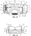
- the protector 40 when the protector 40 is slid on the shaving razor 10, as shown for example in figure 12 , there is a gap 54 between the bearing 19 being the nearest to the side wall 51 among the first and the second bearings 19 and 20.
- the gap 54 separates the bearing 19 being the nearest to the side wall 51 and the side wall 51 of a distance 55 comprised between 0,1 mm and 10 mm or 0,2 mm and 5mm.
- This gap 54 provides thus a safe distance between the bearing 19 that is the nearest to the side wall 51 and the side wall 51.
- the side wall 51 In case of a shock, the side wall 51 is hit first.
- the side wall 51 can thus act as a shield or be deformed or even brake. But the distance 55 of the gap 54 is intended to prevent transmission of the shock to the nearest bearing 19.
- the nearest bearing 19 is thus protected against this shock.
- Figures 10 and 11 illustrate the front wall 52.
- the front wall 52 extends over the first opening 49 of the upper wall 44 of the housing 42.
- the front wall 52 has thus a free end 61, which is opposite to the upper wall 44.
- Figure 13 also illustrates the front wall 52.
- the front wall 52 has a width 56 comprised between 15 mm and 400 mm, along the axis W.
- the width 56 of the front wall 52 is the largest at the contacting portion with the upper wall 44 of the housing 42. The largest value at this location should be at least as larger of the width 15 of the front portion 14 of the handle 12.
- the width 56 of the front wall 52 can be of about 30mm.
- the front wall 52 has also a height 58, along an axis H.
- the height 58 is measured between the upper wall 44 of the housing 42 and the free end 61 of the front wall 52.
- the height 58 of the front wall 52 may be enough to sufficiently cover the front portion 14 of the handle 12.
- the height 58 of the front wall 52 is comprised between 3 mm and 15 mm. More preferably, the height 58 of the front wall 52 is about 9mm.
- the front wall 52 extends over the first opening 49 of the upper wall 44 of the housing 42. More precisely, we can see in this figure 11 that the front wall 52 is tilted of an acute angle ⁇ relative to the upper wall 44 of the housing 42. This angle ⁇ generally corresponds to the angle ⁇ between the handle 12 and the cartridge 22, when the shaving razor 10 is in a rest position.
- the front wall 52 of the guiding member 50 has an outer surface 59 and an inner surface 60.
- the shape of the inner surface 60 of the front wall 52 may match with the overall shape of the front surface 32 of the handle 12, in the area of the front portion 14. Therefore, according to the cross sectional view along the median axis M of the protector of the figure 5 , the inner surface 60 has a tangent line 62 which makes an acute angle ⁇ with the tangent plane 63 of the upper wall 44 of the housing 42.
- This angle ⁇ is identical or slightly larger than the angle ⁇ .
- the angle ⁇ is comprised between 35 degrees and 70 degrees or 40 and 60 degrees.
- the angle ⁇ is of about 55 degrees.
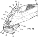
- Such a configuration allows a suitable cooperation between the handle 12 and the guiding member 50. So, when assembled on the shaving razor 10, as it can be seen in figure 14 or 15 , the guiding member 50 slightly goes up from the upper wall 44 of the housing 42 along the front portion 14 of the handle 12. Thanks to their configuration, the front wall 52 and the side wall 51 form a path for guiding the handle 12 toward the cartridge 22, when the handle 12 is going to be attached to the cartridge 22.
- the present disclosure further concerns a method for attaching the handle 12 to the cartridge 22.
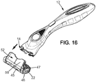
- the method is as follow, and is described partly in relation with figure 16 .
- the cartridge 22 is placed in the housing 42 of the protector 40.
- the handle 12 is approached toward the assembly made by the protector 40 and the cartridge 22.
- the handle 12 approaches to the guiding member 50, the handle 12 follows the path formed by the guiding member 50 and is thus directed in the correct direction towards the cartridge 22.
- the guiding member 50 serves as a mistake-proofing in order to attach the handle 12 to the cartridge 22 in the correct way.
- the handle 12 is thus properly attached to the cartridge 22.
- the handle 12, the cartridge 22 and the protector 40 form therefore a razor system 11.
- the razor system 11 is, in this configuration, well protected.
- the cartridge 22 cannot be detached inadvertently from the handle 12. Besides, the cartridge 22 is protected from dust. Also, since the protector 40 covers the cutting edges 29 of the blades 28, there exists no risk of inadvertently cutting with such a razor system 11.
- the present invention also concerns a method for removing the protector 40 of the shaving razor 10.
- the protector 40 is removed from the razor system 11 by sliding the shaving razor 10 through the second opening 53 of the housing 42 of the protector 40.
- the shaving razor 10 is, in this configuration, ready for shaving.
- the protector 40 may be provided with connecting means which allow the protector 40 to be releasably attached to another protector, itself releasably attached to another one, etc.
- Such an assembly of protectors releasably attached one to another one are like a string or rosary.
- the lateral wall 45 can be provided with one or more elongated projection(s) 118, which is(are) rounded in cross-section (see FIGS. 5 and 8 ) and is(are) disposed lengthwise along the longitudinal axis of the lateral wall 45.
- the lateral wall 47 is in that case provided with two rows of projections, a top row of projections 120a, 120b, and 120c and a bottom row of projections 122a and 122b.
- the projections 120a, 120b, and 120c in the top row are arced downward, and the projections 122a and 122b in the bottom row are arced upward.
- the top and bottom rows of projections form a slot capable of interconnectingly receiving an element having the same shape as the elongated projection(s) 118.
- the disclosure is not limited to the three projections 120a, 120b, and 120c on the top row and two projections 122a and 122b on the bottom row, it is understood that any number of projections may be used.
- the projection 118 on lateral wall 45 may be formed as a plurality of projections rather than as a single, elongated projection.
- the projections on lateral wall 45 and lateral wall 47 enable the interlocking connection of multiple protectors 40 (not depicted on the figures).
- the protectors 40 can be connected together by sliding the elongated projection 118 of one protector into the slot formed by the projections (120a, 120b, 120c, 122a, and 122b) on lateral wall 47 of another protector.
- the projections on lateral wall 47 are manufactured from a resiliently yieldable material, and the elongated projection 118 may be snapped into the slot formed by the projections on lateral wall 47 by pushing the elongated projection 118 into the slot.
- the present disclosure allows any number of protectors to be connected together. Moreover, the protectors may be attached and detached as needed.
Landscapes
- Life Sciences & Earth Sciences (AREA)
- Forests & Forestry (AREA)
- Engineering & Computer Science (AREA)
- Mechanical Engineering (AREA)
- Packaging Of Annular Or Rod-Shaped Articles, Wearing Apparel, Cassettes, Or The Like (AREA)
Abstract
A protector (40) for a shaving razor (10), the shaving razor (10) comprising a handle (12) removably attached to a cartridge (22), the protector (40) comprising a housing (42) for receiving and protecting the cartridge (22), the housing (42) comprising a bottom wall (43), an upper wall (44) and lateral walls (45, 46, 47, 48), the upper wall (44) being provided with a first opening (49) for receiving the handle (12), the protector (40) further comprising a guiding member (50), for guiding the handle (12) toward the cartridge (22) when the handle (12) is being attached to the cartridge (22).
Description
- The disclosure relates to a protector for a shaving razor and a razor system comprising such a protector. More particularly, the protector has a protective function for the shaving razor and a guiding function for the handle in the correct orientation when the handle is to be attached to the cartridge. The invention also relates to a method for attaching the handle to the cartridge with the protector, and a method for removing the protector when the handle is attached to the cartridge.
- Shaving razors commonly comprise a handle and a cartridge. The handle is removably and pivotally attached to the cartridge, so that the cartridge, or the handle, can be thrown when it is worn. It may beimportant to protect the cartridge and the pivoting attachment between the cartridge and the handle, which can be damaged in case of a drop for example. To this aim, document
EP2231371B discloses a protector for a cartridge of a shaving razor, the protector having inhibiting members that engage the pivoting and removable attachment between the cartridge and the handle thus preventing the cartridge from pivoting with respect to the handle. However, it has been observed that the handle can be attached to the cartridge in the wrong way, therefore damaging the attachment between the cartridge and the handle and create safety issues for the user. Additionally, the disclosure enables improvements in the shaving area. - A protector according to the invention is provided for a shaving razor, the shaving razor comprising a handle removably attached to a cartridge, the protector comprising a housing for receiving and protecting the cartridge, the housing comprising a bottom wall, an upper wall and lateral walls, the upper wall being provided with a first opening for receiving the handle, wherein the protector further comprises a guiding member for guiding the handle toward the cartridge when the handle is being attached to the cartridge. Therefore, the protector guides the user in attaching the cartridge in a correct orientation.
- In further embodiments , one or more of the following features may be incorporated in the protector of the invention, alone or in combination:
- The guiding member extends from the upper wall of the housing. So, the guiding member slightly extends over the handle, when connected to the cartridge. In case of a shaving razor with a pivot movement of the cartridge relative to the handle, such a guiding member inhibits the movement of the cartridge.
- The guiding member comprises a front wall.
- The front wall is provided with an outer flap and the outer flap has one or more bumps. The bump(s) serves as finger rest area for the user, directing the user when locking the protector onto the cartridge.
- The front wall extends over the first opening of the upper wall of the housing. The protector guides the handle towards the head at the correct angle.
- The front wall of the guiding member makes an acute angle α with the upper wall of the housing.
- The angle α is comprised between 35 degrees and 70 degrees or 40 and 60 degrees. Such an inclination forces the user to orient the handle of the shaving razor in the correct way in view of the attachment of the handle with the cartridge.
- The guiding member comprises a side wall.
- The side wall of the guiding member forms an angle χ with the upper wall of the housing. In this configuration, the side wall provides structural reinforcement of the front wall. Actually, the side wall of the guiding member can form an angle of 90° (or right angle) with the upper wall of the housing.
- The side wall and the front wall of the guiding member are continuous. The side wall and the front wall form thereby a path for guiding the handle toward the cartridge., which ease the attachment of the handle on the cartridge.
- A lateral wall of the housing further comprises a second opening for sliding the cartridge into the housing. The protector can thus be slid on the cartridge to protect the cartridge and can be removed for shaving. The protector may have an indicator, such as an arrow, showing the sliding direction.
- The shaving razor comprises a handle and a cartridge, the handle being removably attached to a cartridge.
- The handle comprises a first connecting portion, the cartridge comprises a second connecting portion, and the first and the second connecting portions are adapted to be connected together.
- The side wall of the guiding member and the first connecting portion of the handle are spaced from each other by a distance in a range comprised between 0,1 mm and 10 mm or 0,2 mm and 5 mm. Further objects of the present disclosure pertains to methods for attaching a handle to a cartridge, forming thus a razor system, the cartridge being protected by the protector as described above, in which when the handle is being attached to the cartridge, the handle follows a path formed by the front wall and the side wall of the guiding member of the protector.
- Further objects are methods for removing the protector as described above from a razor system, the razor system further comprising a handle connected to a cartridge, the protector being removed from the razor system by sliding through the second opening of the housing of the protector. The razor can thus be used for shaving. After shaving, the protector can be slid again on the cartridge to protect the last from contaminan. and to protect the user from inadvertent cutting. In addition, thanks to the guiding member, the handle cannot be inadvertent detached from the cartridge.
- Other characteristics and advantages of the disclosure will readily appear from the following description of one embodiment, provided as non-limitative examples, in reference to the accompanying drawings.
-
Figure 1 is a perspective view of the described razor system. -
Figure 2 is another perspective view of described the razor system. -
Figure 3 is an exploded perspective top view of the shaving razor. -
Figure 4 is an exploded perspective view from below of the shaving razor. -
Figure 5 is a cross-sectional view along the median axis of the razor system -
Figure 6 is a cross-sectional view along the median axis of the shaving razor. -
Figure 7 is a perspective top view of the protector and the cartridge. -
Figure 8 is a lateral view of the protector. -
Figure 9 is a front view of the protector. -
Figure 10 is a perspective view of the protector. -
Figure 11 is a perspective top view of the razor system, in the area of the front portion of the handle. -
Figure 12 is a top view of the razor system, in the area of the front portion of the handle. -
Figure 13 is another front view of the protector. -
Figure 14 is an overall top view of the razor system. -
Figure 15 is a perspective view of the protector offigure 13 . -
Figure 16 is a perspective view of the razor system. -
Figures 1 and 2 illustrate arazor system 11, comprising aprotector 40 and ashaving razor 10. Theshaving razor 10 comprises ahandle 12 and acartridge 22. Thehandle 12 and thecartridge 22 are removably attached together. In addition, thecartridge 22 can rotate relative to thehandle 12, about a pivot axis P. - As depicted in
figures 3 and 4 , thehandle 12 comprises abody 13, extending along a longitudinal direction L, and afront portion 14. Thefront portion 14 has awidth 15 along a first transversal axis X, comprised between 10 mm and 40 mm or 25mm to 35mm. More preferably, thewidth 15 of thefront portion 14, taken at its largest point, is about 30mm. Thefront portion 14 is provided for the attachment with thecartridge 22. Still infigures 3 and 4 , thefront portion 14 and thecartridge 22 have anattachment mechanism 16. Theattachment mechanism 16 enables to selectively connect thecartridge 22 to thehandle 12 or release thecartridge 22 from the last, in order, for example to change thecartridge 22 when it is worn off. More particularly, theattachment mechanism 16 comprises a first and a second connectingportions portions handle 12 comprises the first connectingportion 17 and thecartridge 22 comprises the second connectingportion 18. - The first connecting
portion 17 extends toward two free ends, on both sides of thefront portion 14 of thehandle 12. The free ends of the first connectingportion 17 can be provided respectively with afirst bearing 19 and asecond bearing 20. In particular, thefirst bearing 19 and thesecond bearing 20 can be shell bearings, as depicted infigure 3 . The shell bearings are exposed toward the outside of thefront portion 14 of thehandle 12. - The
cartridge 22, as shown infigure 3 , extends along a second transversal axis X'. Thecartridge 22 has afront surface 24 and arear surface 26. Thecartridge 22 comprises elongatedblades 28. Eachblade 28 has acutting edge 29 extending along the second transversal axis X'. The cutting edges 29 are on the side of thefront surface 24.Figure 4 shows acartridge 22 with threeblades 28. However, thecartridge 22 according to the invention is not limited to such a number of blades. Actually, thecartridge 22 can be provided with at least oneblade 28 and up to, for example,tenblades 28. For example, thecartridge 22 can be provided with fiveblades 28. In addition, thecartridge 22 has the second connectingportion 18. The second connectingportion 18 comprises first and secondprotruding connectors Figure 3 shows the first and secondprotruding connectors cutting edge 29. Thus, the first and secondprotruding connectors rear surface 26. The first and secondprotruding connectors second bearings handle 12. Shapes of the first and secondprotruding connectors second bearings handle 12. Such a complementarity of shapes allows a pivot movement of thecartridge 22 relative to thehandle 12. - Regarding the arrangement of the different axes with respect to one another, the pivot axis P is parallel to the first transversal axis X. The second transversal axis X' is parallel to the first parallel axis X. The pivot axis P is parallel to the second transversal axis X'.
- The shaving
razor 10 has two extreme positions. For instance, the two extreme positions are a rest position (figure 5 ), and an extended position (figure 6 ). The extended position corresponds to the position resulting from the pivot movement of thecartridge 22 in relation with thehandle 12. In the rest position, thehandle 12 makes an angle β of about 55 degrees with thecartridge 22. More precisely, the angle β is an acute angle. This angle. β is comprised between 35 degrees and 70 degrees or 40 degrees to 60 degrees. Actually, as depicted in thefigure 2 , thehandle 12 has an outer surface divided in afront surface 32 and aback surface 33. Thefront surface 32 of thehandle 12 forms atangent line 34 in thefigure 5 . The angle β is actually the angle made between thetangent line 34 and therear surface 26 of thecartridge 22. - The
protector 40 is illustrated infigures 1, 2 ,6 and followings. Theprotector 40 has ahousing 42 and a guidingmember 50. Thehousing 42 is shaped for receiving thecartridge 22 of the shavingrazor 10. The overall inner shape of thehousing 42 is thus similar to the outer shaper of thecartridge 22. Thehousing 42 comprises abottom wall 43, anupper wall 44 andlateral walls upper wall 44 comprises afirst opening 49 for attaching the cartridge to the handle, thefirst opening 49 being provided for sliding thecartridge 22 inside thehousing 42. There are four lateral walls: a firstlateral wall 45, a secondlateral wall 46, a thirdlateral wall 47 and a fourthlateral wall 48. The lateral walls may have dimensions that are identical two by two. In embodiments, two opposite lateral walls may have identical dimensions. As illustrated infigure 7 , the length of the firstlateral wall 45 is larger than the length of the secondlateral wall 46. The length of the secondlateral wall 46 is smaller than the length of the thirdlateral wall 47. The length of the thirdlateral wall 47 is larger than the length of the fourthlateral wall 48. The lengths of the first and the thirdlateral walls lateral walls lateral wall 48 has asecond opening 53. Thesecond opening 53 is provided for sliding thecartridge 22 into the housing. - The
protector 40 further comprises a guidingmember 50. The guidingmember 50 extends away from theupper wall 44 of thecartridge 22. More precisely, the guidingmember 50 comprises aside wall 51 and afront wall 52. As depicted infigure 10 , theside wall 51 and thefront wall 52 define a part of the edge of thefirst opening 49 of theupper wall 44. Theside wall 51 and thefront wall 52 are joined together. They form a right angle (i.e. 90 degrees) with each other. - The
front wall 52 may be provided with an outer flap 52'. This outer flap 52' extends opposite thefirst opening 49 of theupper wall 44. The outer flap 52' may be provided with one ormore bumps 52". As depicted on the figures, the numbers ofbumps 52" can be of seven, but is not limited to this number. These bumps can serve as finger rest area for the user, directing the user when locking the protector onto the cartridge. - The
side wall 51 extends from theupper wall 44 of thehousing 42. Theside wall 51 forms thus an angle χ with theupper wall 44 of thehousing 42. In embodiments, as depicted infigure 9 , theside wall 51 may extend in a plane S perpendicular to theupper wall 44 of thehousing 42. In other words, theside wall 51 of the guiding member forms an angle χ of about 90° (or right angle) with the upper wall of the housing. Theside wall 51 has a function of protection of the head to handle attachment, for example in case of a shock. In other words, theside wall 51 acts as a cover for the attachment. Indeed, when theprotector 40 is slid on the shavingrazor 10, as shown for example infigure 12 , there is a gap 54 between the bearing 19 being the nearest to theside wall 51 among the first and thesecond bearings bearing 19 being the nearest to theside wall 51 and theside wall 51 of a distance 55 comprised between 0,1 mm and 10 mm or 0,2 mm and 5mm. This gap 54 provides thus a safe distance between the bearing 19 that is the nearest to theside wall 51 and theside wall 51. In case of a shock, theside wall 51 is hit first. Theside wall 51 can thus act as a shield or be deformed or even brake. But the distance 55 of the gap 54 is intended to prevent transmission of the shock to thenearest bearing 19. Thenearest bearing 19 is thus protected against this shock. -
Figures 10 and 11 illustrate thefront wall 52. Thefront wall 52 extends over thefirst opening 49 of theupper wall 44 of thehousing 42. Thefront wall 52 has thus afree end 61, which is opposite to theupper wall 44.Figure 13 also illustrates thefront wall 52. Thefront wall 52 has awidth 56 comprised between 15 mm and 400 mm, along the axis W. Actually, thewidth 56 of thefront wall 52 is the largest at the contacting portion with theupper wall 44 of thehousing 42. The largest value at this location should be at least as larger of thewidth 15 of thefront portion 14 of thehandle 12. Thewidth 56 of thefront wall 52 can be of about 30mm. Thefront wall 52 has also aheight 58, along an axis H. Theheight 58 is measured between theupper wall 44 of thehousing 42 and thefree end 61 of thefront wall 52. Theheight 58 of thefront wall 52 may be enough to sufficiently cover thefront portion 14 of thehandle 12. For example, theheight 58 of thefront wall 52 is comprised between 3 mm and 15 mm. More preferably, theheight 58 of thefront wall 52 is about 9mm. As shown for example infigure 11 , thefront wall 52 extends over thefirst opening 49 of theupper wall 44 of thehousing 42. More precisely, we can see in thisfigure 11 that thefront wall 52 is tilted of an acute angle α relative to theupper wall 44 of thehousing 42. This angle α generally corresponds to the angle β between thehandle 12 and thecartridge 22, when the shavingrazor 10 is in a rest position. This angle α is chosen accordingly with the shape of thehandle 12. Therefore, as shown infigure 5 , thefront wall 52 of the guidingmember 50 has anouter surface 59 and aninner surface 60. The shape of theinner surface 60 of thefront wall 52 may match with the overall shape of thefront surface 32 of thehandle 12, in the area of thefront portion 14. Therefore, according to the cross sectional view along the median axis M of the protector of thefigure 5 , theinner surface 60 has atangent line 62 which makes an acute angle α with the tangent plane 63 of theupper wall 44 of thehousing 42. This angle α is identical or slightly larger than the angle β. For example, the angle α is comprised between 35 degrees and 70 degrees or 40 and 60 degrees. The angle α is of about 55 degrees. Such a configuration allows a suitable cooperation between thehandle 12 and the guidingmember 50. So, when assembled on the shavingrazor 10, as it can be seen infigure 14 or15 , the guidingmember 50 slightly goes up from theupper wall 44 of thehousing 42 along thefront portion 14 of thehandle 12. Thanks to their configuration, thefront wall 52 and theside wall 51 form a path for guiding thehandle 12 toward thecartridge 22, when thehandle 12 is going to be attached to thecartridge 22. - The present disclosure further concerns a method for attaching the
handle 12 to thecartridge 22. The method is as follow, and is described partly in relation withfigure 16 . Beforehand, thecartridge 22 is placed in thehousing 42 of theprotector 40. Then, thehandle 12 is approached toward the assembly made by theprotector 40 and thecartridge 22. When thehandle 12 approaches to the guidingmember 50, thehandle 12 follows the path formed by the guidingmember 50 and is thus directed in the correct direction towards thecartridge 22. In other words, the guidingmember 50 serves as a mistake-proofing in order to attach thehandle 12 to thecartridge 22 in the correct way. Finally, thehandle 12 is thus properly attached to thecartridge 22. Thehandle 12, thecartridge 22 and theprotector 40 form therefore arazor system 11. Therazor system 11 is, in this configuration, well protected. More precisely, thecartridge 22 cannot be detached inadvertently from thehandle 12. Besides, thecartridge 22 is protected from dust. Also, since theprotector 40 covers the cutting edges 29 of theblades 28, there exists no risk of inadvertently cutting with such arazor system 11. - The present invention also concerns a method for removing the
protector 40 of the shavingrazor 10. To this aim, theprotector 40 is removed from therazor system 11 by sliding the shavingrazor 10 through thesecond opening 53 of thehousing 42 of theprotector 40. The shavingrazor 10 is, in this configuration, ready for shaving. - As shown in
figures 1-2 ,5 ,8-16 , theprotector 40 may be provided with connecting means which allow theprotector 40 to be releasably attached to another protector, itself releasably attached to another one, etc. Such an assembly of protectors releasably attached one to another one are like a string or rosary. - More precisely, the
lateral wall 45 can be provided with one or more elongated projection(s) 118, which is(are) rounded in cross-section (seeFIGS. 5 and8 ) and is(are) disposed lengthwise along the longitudinal axis of thelateral wall 45. Thelateral wall 47 is in that case provided with two rows of projections, a top row ofprojections projections projections projections projections projections projection 118 onlateral wall 45 may be formed as a plurality of projections rather than as a single, elongated projection. - The projections on
lateral wall 45 andlateral wall 47 enable the interlocking connection of multiple protectors 40 (not depicted on the figures). Theprotectors 40 can be connected together by sliding theelongated projection 118 of one protector into the slot formed by the projections (120a, 120b, 120c, 122a, and 122b) onlateral wall 47 of another protector. Alternatively, the projections onlateral wall 47 are manufactured from a resiliently yieldable material, and theelongated projection 118 may be snapped into the slot formed by the projections onlateral wall 47 by pushing theelongated projection 118 into the slot. The present disclosure allows any number of protectors to be connected together. Moreover, the protectors may be attached and detached as needed.
Claims (16)
- A protector (40) for a shaving razor (10), the shaving razor (10) comprising a handle (12) removably attached to a cartridge (22), the protector (40) comprising a housing (42) for receiving and protecting the cartridge (22), the housing (42) comprising a bottom wall (43), an upper wall (44) and lateral walls (45, 46, 47, 48), the upper wall (44) being provided with a first opening (49) for receiving the handle (12), wherein the protector (40) further comprises a guiding member (50), for guiding the handle (12) toward the cartridge (22) when the handle (12) is being attached to the cartridge (22).
- A protector (40) according to claim 1, wherein the guiding member (50) extends from the upper wall (44) of the housing (42).
- A protector (40) according to any of claims 1 or 2, wherein the guiding member (50) comprises a front wall (52).
- A protector according to claim 3, wherein the front wall (52) is provided with an outer flap (52') and wherein the outer flap (52') has one or more bumps (52").
- A protector according to claim 3 or 4, wherein the front wall (52) extends over the first opening (49) of the upper wall (44) of the housing (42).
- A protector according to any of claims 3 to 5, wherein the front wall (52) of the guiding member (50) makes an acute angle (α) with the upper wall (44) of the housing (42).
- A protector (40) according to claim 6, wherein the angle (α) is comprised between 35 degrees and 70 degrees.
- A protector (40) according to any of claims 1 to 7, wherein the guiding member (50) comprises a side wall (51).
- A protector (40) according to claim 8, wherein the side wall (51) of the guiding member (50) forms an angle (χ) with the upper wall (44) of the housing (42).
- A protector (40) according to any of claims 8 or 9, wherein the side wall (51) and the front wall (52) of the guiding member (50) are continuous.
- A protector according to any of claims 1 to 10, wherein a lateral wall (48) of the housing (42) further comprises a second opening (53) for sliding the cartridge (22) into the housing (42).
- A razor system (11) comprising a shaving razor (10) and a protector (40) according to any of claims 1 to 11, wherein the shaving razor (10) comprises a handle (12) and a cartridge (22), the handle (12) being removably attached to a cartridge (22).
- A razor system (11) according to claim 12, wherein the handle (12) comprises a first connecting portion (17), the cartridge (22) comprises a second connecting portion (18), and wherein the first and the second connecting portions (17, 18) are adapted to be connected together.
- A razor system according to claim 13, wherein the side wall (51) of the guiding member (50) and the first connecting portion (17) of the handle (12) are spaced from each other by a distance (55) in a range comprised between 0,1 mm and 10 mm.
- A method for attaching a handle (12) to a cartridge (22), forming thus a razor system (11), the cartridge (22) being protected by the protector (40) of any of claims 1 to 11, wherein when the handle (12) is being attached to the cartridge (22), the handle (12) follows a path formed by the front wall (52) and the side wall (51) of the guiding member (50) of the protector (40).
- A method for removing the protector (40) of claim 11 from a razor system (11), the razor system (11) further comprising a handle (12) connected to a cartridge (22), the protector (40) being removed from the razor system (11) by sliding through the second opening (53) of the housing (42) of the protector (40).
Priority Applications (2)
| Application Number | Priority Date | Filing Date | Title |
|---|---|---|---|
| EP17152934.0A EP3351357A1 (en) | 2017-01-24 | 2017-01-24 | Razor system |
| US15/816,556 US10493644B2 (en) | 2017-01-24 | 2017-11-17 | Razor system |
Applications Claiming Priority (1)
| Application Number | Priority Date | Filing Date | Title |
|---|---|---|---|
| EP17152934.0A EP3351357A1 (en) | 2017-01-24 | 2017-01-24 | Razor system |
Publications (1)
| Publication Number | Publication Date |
|---|---|
| EP3351357A1 true EP3351357A1 (en) | 2018-07-25 |
Family
ID=57890720
Family Applications (1)
| Application Number | Title | Priority Date | Filing Date |
|---|---|---|---|
| EP17152934.0A Withdrawn EP3351357A1 (en) | 2017-01-24 | 2017-01-24 | Razor system |
Country Status (2)
| Country | Link |
|---|---|
| US (1) | US10493644B2 (en) |
| EP (1) | EP3351357A1 (en) |
Cited By (1)
| Publication number | Priority date | Publication date | Assignee | Title |
|---|---|---|---|---|
| US20180207824A1 (en) * | 2017-01-24 | 2018-07-26 | Bic Violex S.A. | Razor system |
Families Citing this family (3)
| Publication number | Priority date | Publication date | Assignee | Title |
|---|---|---|---|---|
| US11224983B2 (en) * | 2014-12-10 | 2022-01-18 | Bic-Volex Sa | Shaving blade assembly comprising a blade unit and a skin contact member and a razor comprising a razor handle and such a shaving blade assembly |
| US11298842B2 (en) * | 2018-09-05 | 2022-04-12 | The Gillette Company Llc | Razor structure |
| US11345055B2 (en) | 2018-09-05 | 2022-05-31 | The Gillette Company Llc | Razor cartridge structure |
Citations (3)
| Publication number | Priority date | Publication date | Assignee | Title |
|---|---|---|---|---|
| US3287803A (en) * | 1965-04-12 | 1966-11-29 | John A Wauters | Razor protector |
| US20090007432A1 (en) * | 2007-07-06 | 2009-01-08 | I-Chiun Precision Industry Co., Ltd. | Holder for razor head |
| US20090172957A1 (en) * | 2008-01-08 | 2009-07-09 | Prudden Jr John | Pivot inhibiting protective razor cover |
Family Cites Families (10)
| Publication number | Priority date | Publication date | Assignee | Title |
|---|---|---|---|---|
| US4587730A (en) * | 1981-09-30 | 1986-05-13 | American Safety Razor Company | Sleeve for disposable safety razor |
| US4709476A (en) * | 1986-10-08 | 1987-12-01 | The Gillette Company | Safety razor system |
| US5893213A (en) * | 1997-05-12 | 1999-04-13 | Warner-Lambert Company | Protective cover for shaving cartridge |
| ES2368897T3 (en) * | 2006-08-25 | 2011-11-23 | Bic Violex S.A. | SHAVING BLADE UNIT AND SHAVING MACHINE THAT HAS SUCH BLADE UNIT. |
| US20110005089A1 (en) * | 2009-07-10 | 2011-01-13 | Richard Kevin Sennett | Cover for shaving cartridges |
| US20110203124A1 (en) * | 2010-02-19 | 2011-08-25 | Kelly Daniel Bridges | Protective Covers for Wet Shaving Razors |
| USD629969S1 (en) * | 2010-05-11 | 2010-12-28 | American Safety Razor | Razor cartridge protector |
| PL3383603T3 (en) * | 2015-12-01 | 2021-12-13 | Bic Violex S.A. | Shaving razors and shaving cartridges |
| BR112018008162B1 (en) * | 2015-12-01 | 2021-06-01 | Bic-Violex Sa | SHAVING CARTRIDGE AND SHAVING BLADE |
| EP3351357A1 (en) * | 2017-01-24 | 2018-07-25 | BIC-Violex S.A. | Razor system |
-
2017
- 2017-01-24 EP EP17152934.0A patent/EP3351357A1/en not_active Withdrawn
- 2017-11-17 US US15/816,556 patent/US10493644B2/en active Active
Patent Citations (4)
| Publication number | Priority date | Publication date | Assignee | Title |
|---|---|---|---|---|
| US3287803A (en) * | 1965-04-12 | 1966-11-29 | John A Wauters | Razor protector |
| US20090007432A1 (en) * | 2007-07-06 | 2009-01-08 | I-Chiun Precision Industry Co., Ltd. | Holder for razor head |
| US20090172957A1 (en) * | 2008-01-08 | 2009-07-09 | Prudden Jr John | Pivot inhibiting protective razor cover |
| EP2231371B1 (en) | 2008-01-08 | 2012-10-24 | The Gillette Company | Pivot inhibiting protective razor cover |
Cited By (2)
| Publication number | Priority date | Publication date | Assignee | Title |
|---|---|---|---|---|
| US20180207824A1 (en) * | 2017-01-24 | 2018-07-26 | Bic Violex S.A. | Razor system |
| US10493644B2 (en) * | 2017-01-24 | 2019-12-03 | Bic Violex S.A. | Razor system |
Also Published As
| Publication number | Publication date |
|---|---|
| US20180207824A1 (en) | 2018-07-26 |
| US10493644B2 (en) | 2019-12-03 |
Similar Documents
| Publication | Publication Date | Title |
|---|---|---|
| EP3998892B1 (en) | Protective helmet with face protection shield and linkage mechanism | |
| US10493644B2 (en) | Razor system | |
| EP2026935B1 (en) | Razor handle | |
| EP2853362B1 (en) | A shaving blade cartridge | |
| US9032627B2 (en) | Shaving blade unit and shaver having such a blade unit | |
| EP3681328B1 (en) | Protective helmet | |
| US20110197450A1 (en) | Shaving razor adapter attaching a shaving razor cartridge to a shaving razor handle | |
| US20090032043A1 (en) | Hair cutting comb with T-top member | |
| EP2056995B1 (en) | Shaving blade unit comprising a movable trimming blade protector and shaver having such a blade unit | |
| KR102712226B1 (en) | Shaving head | |
| EP2231371B1 (en) | Pivot inhibiting protective razor cover | |
| CN101790335A (en) | Razor storage case having cartridge securing supports | |
| EP3094453B1 (en) | Connecting member for a razor | |
| US20130199047A1 (en) | Cutting tool | |
| JPH09504463A (en) | Razor head with multiple blades for improved performance | |
| US20130298740A1 (en) | Multifunction safety knife | |
| US20020133952A1 (en) | Knife blade guard | |
| EP2557574B1 (en) | Sheath for electric cable and trimmer | |
| JP6196784B2 (en) | Protective cap | |
| KR102898499B1 (en) | Dispenser for Razor Cartridge | |
| EP1383633B1 (en) | Knife blade guard | |
| CA1261635A (en) | Crop fingers for harvesters |
Legal Events
| Date | Code | Title | Description |
|---|---|---|---|
| PUAI | Public reference made under article 153(3) epc to a published international application that has entered the european phase |
Free format text: ORIGINAL CODE: 0009012 |
|
| STAA | Information on the status of an ep patent application or granted ep patent |
Free format text: STATUS: THE APPLICATION HAS BEEN PUBLISHED |
|
| AK | Designated contracting states |
Kind code of ref document: A1 Designated state(s): AL AT BE BG CH CY CZ DE DK EE ES FI FR GB GR HR HU IE IS IT LI LT LU LV MC MK MT NL NO PL PT RO RS SE SI SK SM TR |
|
| AX | Request for extension of the european patent |
Extension state: BA ME |
|
| STAA | Information on the status of an ep patent application or granted ep patent |
Free format text: STATUS: THE APPLICATION IS DEEMED TO BE WITHDRAWN |
|
| 18D | Application deemed to be withdrawn |
Effective date: 20190126 |