EP3351308A1 - Adjustable cantilevered paint apparatus actuation system - Google Patents
Adjustable cantilevered paint apparatus actuation system Download PDFInfo
- Publication number
- EP3351308A1 EP3351308A1 EP17204943.9A EP17204943A EP3351308A1 EP 3351308 A1 EP3351308 A1 EP 3351308A1 EP 17204943 A EP17204943 A EP 17204943A EP 3351308 A1 EP3351308 A1 EP 3351308A1
- Authority
- EP
- European Patent Office
- Prior art keywords
- phalange
- surface treatment
- contoured
- actuator
- base
- Prior art date
- Legal status (The legal status is an assumption and is not a legal conclusion. Google has not performed a legal analysis and makes no representation as to the accuracy of the status listed.)
- Granted
Links
Images




Classifications
-
- B—PERFORMING OPERATIONS; TRANSPORTING
- B05—SPRAYING OR ATOMISING IN GENERAL; APPLYING FLUENT MATERIALS TO SURFACES, IN GENERAL
- B05B—SPRAYING APPARATUS; ATOMISING APPARATUS; NOZZLES
- B05B3/00—Spraying or sprinkling apparatus with moving outlet elements or moving deflecting elements
- B05B3/02—Spraying or sprinkling apparatus with moving outlet elements or moving deflecting elements with rotating elements
- B05B3/12—Spraying or sprinkling apparatus with moving outlet elements or moving deflecting elements with rotating elements with spray booms or the like rotating around an axis by means independent of the liquid or other fluent material discharged
-
- B—PERFORMING OPERATIONS; TRANSPORTING
- B05—SPRAYING OR ATOMISING IN GENERAL; APPLYING FLUENT MATERIALS TO SURFACES, IN GENERAL
- B05B—SPRAYING APPARATUS; ATOMISING APPARATUS; NOZZLES
- B05B13/00—Machines or plants for applying liquids or other fluent materials to surfaces of objects or other work by spraying, not covered by groups B05B1/00 - B05B11/00
- B05B13/02—Means for supporting work; Arrangement or mounting of spray heads; Adaptation or arrangement of means for feeding work
- B05B13/04—Means for supporting work; Arrangement or mounting of spray heads; Adaptation or arrangement of means for feeding work the spray heads being moved during spraying operation
- B05B13/0405—Means for supporting work; Arrangement or mounting of spray heads; Adaptation or arrangement of means for feeding work the spray heads being moved during spraying operation with reciprocating or oscillating spray heads
- B05B13/041—Means for supporting work; Arrangement or mounting of spray heads; Adaptation or arrangement of means for feeding work the spray heads being moved during spraying operation with reciprocating or oscillating spray heads with spray heads reciprocating along a straight line
-
- B—PERFORMING OPERATIONS; TRANSPORTING
- B05—SPRAYING OR ATOMISING IN GENERAL; APPLYING FLUENT MATERIALS TO SURFACES, IN GENERAL
- B05B—SPRAYING APPARATUS; ATOMISING APPARATUS; NOZZLES
- B05B1/00—Nozzles, spray heads or other outlets, with or without auxiliary devices such as valves, heating means
- B05B1/14—Nozzles, spray heads or other outlets, with or without auxiliary devices such as valves, heating means with multiple outlet openings; with strainers in or outside the outlet opening
-
- B—PERFORMING OPERATIONS; TRANSPORTING
- B05—SPRAYING OR ATOMISING IN GENERAL; APPLYING FLUENT MATERIALS TO SURFACES, IN GENERAL
- B05B—SPRAYING APPARATUS; ATOMISING APPARATUS; NOZZLES
- B05B12/00—Arrangements for controlling delivery; Arrangements for controlling the spray area
- B05B12/08—Arrangements for controlling delivery; Arrangements for controlling the spray area responsive to condition of liquid or other fluent material to be discharged, of ambient medium or of target ; responsive to condition of spray devices or of supply means, e.g. pipes, pumps or their drive means
- B05B12/12—Arrangements for controlling delivery; Arrangements for controlling the spray area responsive to condition of liquid or other fluent material to be discharged, of ambient medium or of target ; responsive to condition of spray devices or of supply means, e.g. pipes, pumps or their drive means responsive to conditions of ambient medium or target, e.g. humidity, temperature position or movement of the target relative to the spray apparatus
- B05B12/124—Arrangements for controlling delivery; Arrangements for controlling the spray area responsive to condition of liquid or other fluent material to be discharged, of ambient medium or of target ; responsive to condition of spray devices or of supply means, e.g. pipes, pumps or their drive means responsive to conditions of ambient medium or target, e.g. humidity, temperature position or movement of the target relative to the spray apparatus responsive to distance between spray apparatus and target
-
- B—PERFORMING OPERATIONS; TRANSPORTING
- B05—SPRAYING OR ATOMISING IN GENERAL; APPLYING FLUENT MATERIALS TO SURFACES, IN GENERAL
- B05B—SPRAYING APPARATUS; ATOMISING APPARATUS; NOZZLES
- B05B13/00—Machines or plants for applying liquids or other fluent materials to surfaces of objects or other work by spraying, not covered by groups B05B1/00 - B05B11/00
- B05B13/002—Machines or plants for applying coating liquids or other fluent materials by inkjet
-
- B—PERFORMING OPERATIONS; TRANSPORTING
- B05—SPRAYING OR ATOMISING IN GENERAL; APPLYING FLUENT MATERIALS TO SURFACES, IN GENERAL
- B05B—SPRAYING APPARATUS; ATOMISING APPARATUS; NOZZLES
- B05B13/00—Machines or plants for applying liquids or other fluent materials to surfaces of objects or other work by spraying, not covered by groups B05B1/00 - B05B11/00
- B05B13/02—Means for supporting work; Arrangement or mounting of spray heads; Adaptation or arrangement of means for feeding work
- B05B13/0221—Means for supporting work; Arrangement or mounting of spray heads; Adaptation or arrangement of means for feeding work characterised by the means for moving or conveying the objects or other work, e.g. conveyor belts
-
- B—PERFORMING OPERATIONS; TRANSPORTING
- B05—SPRAYING OR ATOMISING IN GENERAL; APPLYING FLUENT MATERIALS TO SURFACES, IN GENERAL
- B05B—SPRAYING APPARATUS; ATOMISING APPARATUS; NOZZLES
- B05B13/00—Machines or plants for applying liquids or other fluent materials to surfaces of objects or other work by spraying, not covered by groups B05B1/00 - B05B11/00
- B05B13/02—Means for supporting work; Arrangement or mounting of spray heads; Adaptation or arrangement of means for feeding work
- B05B13/0278—Arrangement or mounting of spray heads
-
- B—PERFORMING OPERATIONS; TRANSPORTING
- B05—SPRAYING OR ATOMISING IN GENERAL; APPLYING FLUENT MATERIALS TO SURFACES, IN GENERAL
- B05B—SPRAYING APPARATUS; ATOMISING APPARATUS; NOZZLES
- B05B13/00—Machines or plants for applying liquids or other fluent materials to surfaces of objects or other work by spraying, not covered by groups B05B1/00 - B05B11/00
- B05B13/02—Means for supporting work; Arrangement or mounting of spray heads; Adaptation or arrangement of means for feeding work
- B05B13/0285—Stands for supporting individual articles to be sprayed, e.g. doors, vehicle body parts
-
- B—PERFORMING OPERATIONS; TRANSPORTING
- B05—SPRAYING OR ATOMISING IN GENERAL; APPLYING FLUENT MATERIALS TO SURFACES, IN GENERAL
- B05B—SPRAYING APPARATUS; ATOMISING APPARATUS; NOZZLES
- B05B13/00—Machines or plants for applying liquids or other fluent materials to surfaces of objects or other work by spraying, not covered by groups B05B1/00 - B05B11/00
- B05B13/02—Means for supporting work; Arrangement or mounting of spray heads; Adaptation or arrangement of means for feeding work
- B05B13/04—Means for supporting work; Arrangement or mounting of spray heads; Adaptation or arrangement of means for feeding work the spray heads being moved during spraying operation
- B05B13/0436—Installations or apparatus for applying liquid or other fluent material to elongated bodies, e.g. light poles, pipes
-
- B—PERFORMING OPERATIONS; TRANSPORTING
- B05—SPRAYING OR ATOMISING IN GENERAL; APPLYING FLUENT MATERIALS TO SURFACES, IN GENERAL
- B05B—SPRAYING APPARATUS; ATOMISING APPARATUS; NOZZLES
- B05B15/00—Details of spraying plant or spraying apparatus not otherwise provided for; Accessories
- B05B15/60—Arrangements for mounting, supporting or holding spraying apparatus
- B05B15/68—Arrangements for adjusting the position of spray heads
-
- B—PERFORMING OPERATIONS; TRANSPORTING
- B05—SPRAYING OR ATOMISING IN GENERAL; APPLYING FLUENT MATERIALS TO SURFACES, IN GENERAL
- B05B—SPRAYING APPARATUS; ATOMISING APPARATUS; NOZZLES
- B05B3/00—Spraying or sprinkling apparatus with moving outlet elements or moving deflecting elements
- B05B3/02—Spraying or sprinkling apparatus with moving outlet elements or moving deflecting elements with rotating elements
- B05B3/025—Rotational joints
-
- B—PERFORMING OPERATIONS; TRANSPORTING
- B05—SPRAYING OR ATOMISING IN GENERAL; APPLYING FLUENT MATERIALS TO SURFACES, IN GENERAL
- B05D—PROCESSES FOR APPLYING FLUENT MATERIALS TO SURFACES, IN GENERAL
- B05D5/00—Processes for applying liquids or other fluent materials to surfaces to obtain special surface effects, finishes or structures
-
- B—PERFORMING OPERATIONS; TRANSPORTING
- B41—PRINTING; LINING MACHINES; TYPEWRITERS; STAMPS
- B41J—TYPEWRITERS; SELECTIVE PRINTING MECHANISMS, i.e. MECHANISMS PRINTING OTHERWISE THAN FROM A FORME; CORRECTION OF TYPOGRAPHICAL ERRORS
- B41J3/00—Typewriters or selective printing or marking mechanisms characterised by the purpose for which they are constructed
- B41J3/407—Typewriters or selective printing or marking mechanisms characterised by the purpose for which they are constructed for marking on special material
- B41J3/4073—Printing on three-dimensional objects not being in sheet or web form, e.g. spherical or cubic objects
-
- B—PERFORMING OPERATIONS; TRANSPORTING
- B05—SPRAYING OR ATOMISING IN GENERAL; APPLYING FLUENT MATERIALS TO SURFACES, IN GENERAL
- B05B—SPRAYING APPARATUS; ATOMISING APPARATUS; NOZZLES
- B05B13/00—Machines or plants for applying liquids or other fluent materials to surfaces of objects or other work by spraying, not covered by groups B05B1/00 - B05B11/00
- B05B13/02—Means for supporting work; Arrangement or mounting of spray heads; Adaptation or arrangement of means for feeding work
- B05B13/04—Means for supporting work; Arrangement or mounting of spray heads; Adaptation or arrangement of means for feeding work the spray heads being moved during spraying operation
- B05B13/0431—Means for supporting work; Arrangement or mounting of spray heads; Adaptation or arrangement of means for feeding work the spray heads being moved during spraying operation with spray heads moved by robots or articulated arms, e.g. for applying liquid or other fluent material to three-dimensional [3D] surfaces
-
- B—PERFORMING OPERATIONS; TRANSPORTING
- B05—SPRAYING OR ATOMISING IN GENERAL; APPLYING FLUENT MATERIALS TO SURFACES, IN GENERAL
- B05B—SPRAYING APPARATUS; ATOMISING APPARATUS; NOZZLES
- B05B13/00—Machines or plants for applying liquids or other fluent materials to surfaces of objects or other work by spraying, not covered by groups B05B1/00 - B05B11/00
- B05B13/02—Means for supporting work; Arrangement or mounting of spray heads; Adaptation or arrangement of means for feeding work
- B05B13/04—Means for supporting work; Arrangement or mounting of spray heads; Adaptation or arrangement of means for feeding work the spray heads being moved during spraying operation
- B05B13/0431—Means for supporting work; Arrangement or mounting of spray heads; Adaptation or arrangement of means for feeding work the spray heads being moved during spraying operation with spray heads moved by robots or articulated arms, e.g. for applying liquid or other fluent material to three-dimensional [3D] surfaces
- B05B13/0433—Means for supporting work; Arrangement or mounting of spray heads; Adaptation or arrangement of means for feeding work the spray heads being moved during spraying operation with spray heads moved by robots or articulated arms, e.g. for applying liquid or other fluent material to three-dimensional [3D] surfaces the work being vehicle components, e.g. vehicle bodies
-
- B—PERFORMING OPERATIONS; TRANSPORTING
- B05—SPRAYING OR ATOMISING IN GENERAL; APPLYING FLUENT MATERIALS TO SURFACES, IN GENERAL
- B05B—SPRAYING APPARATUS; ATOMISING APPARATUS; NOZZLES
- B05B7/00—Spraying apparatus for discharge of liquids or other fluent materials from two or more sources, e.g. of liquid and air, of powder and gas
- B05B7/02—Spray pistols; Apparatus for discharge
- B05B7/08—Spray pistols; Apparatus for discharge with separate outlet orifices, e.g. to form parallel jets, i.e. the axis of the jets being parallel, to form intersecting jets, i.e. the axis of the jets converging but not necessarily intersecting at a point
- B05B7/0892—Spray pistols; Apparatus for discharge with separate outlet orifices, e.g. to form parallel jets, i.e. the axis of the jets being parallel, to form intersecting jets, i.e. the axis of the jets converging but not necessarily intersecting at a point the outlet orifices for jets constituted by a liquid or a mixture containing a liquid being disposed on a circle
-
- B—PERFORMING OPERATIONS; TRANSPORTING
- B05—SPRAYING OR ATOMISING IN GENERAL; APPLYING FLUENT MATERIALS TO SURFACES, IN GENERAL
- B05D—PROCESSES FOR APPLYING FLUENT MATERIALS TO SURFACES, IN GENERAL
- B05D2254/00—Tubes
- B05D2254/02—Applying the material on the exterior of the tube
Definitions
- the present disclosure relates generally to automated surface treatment assemblies and methods for treating a surface, and more specifically to an automated adjustable surface treatment assembly system and method for treating a contoured surface.
- Surface treatment often requires coating a structural surface that includes a variety of large contoured surfaces.
- coating the structural surfaces includes applying multiple layers of coatings for engineering properties, as well as to apply a decorative livery.
- the decorative livery is applied using a complex process which requires a series of masking operations followed by applying colored paints or coatings where they are needed. These masking and painting operations are serially repeated until the exterior surface treatment is completed. Performing these processes on large areas with a variety of contoured surfaces, therefore, requires a significant amount of time and resources.
- a surface treatment assembly for treating a contoured surface.
- the surface treatment assembly includes a surface treatment array formed from a plurality of base structures and each base structure being operably coupled to a first phalange structure and a first phalange structure first end.
- the surface treatment assembly may further include a second phalange structure operatively coupled to each first phalange structure and a phalange joint disposed between each first phalange structure and each second phalange structure.
- the phalange joint is operably coupled to a first phalange structure second end and a second phalange structure first end, thereby forming a finger structure.
- At least one applicator head is coupled to a second phalange structure second end of each finger structure and each of the at least one applicator head being arranged to treat the contoured surface.
- the surface treatment assembly further includes a base structure actuator operatively coupled to and manipulates the first phalange structure of each finger structure.
- a phalange joint actuator is operatively coupled to and manipulates the second phalange structure of each finger structure. The base structure actuator and the phalange joint actuator adjusts the surface treatment array relative to the contoured surface.
- a method of treating a contoured surface with a surface treatment assembly includes forming a surface treatment array from a plurality of base structures and coupling a finger structure to each base structure of the plurality of base structures.
- the finger structure including a first phalange structure, a second phalange structure and a phalange joint disposed therebetween.
- the method further includes coupling at least one applicator head to the second phalange structure of each finger structure, and each of the at least one applicator head being arranged to apply a surface treatment layer to the contoured surface.
- the method further includes, coupling a base structure actuator to each base structure and a phalange joint actuator to each phalange joint, and manipulating each of the base structure actuators and each of the phalange joint actuators such that the surface treatment array is adjusted relative to the contoured surface.
- a surface treatment system for treating an exterior surface of an airplane.
- the surface treatment system includes a circular surface treatment array formed from a plurality of base structures, each base structure being operably coupled to a first phalange structure at a first phalange structure first end.
- the surface treatment system may further include a second phalange structure operatively coupled to each first phalange structure and a phalange joint disposed between each first phalange structure and each second phalange structure.
- the phalange joint is operably coupled to a first phalange structure second end and a second phalange structure first end, thereby forming a finger structure.
- At least one applicator head is coupled to a second phalange structure second end of each finger structure and each of the at least one applicator head treats a contoured surface along the exterior surface of the airplane.
- the surface treatment assembly further includes a base structure actuator operatively coupled to and manipulates the first phalange structure of each finger structure.
- a phalange joint actuator is operatively coupled to and manipulates the second phalange structure of each finger structure.
- At least one sensor is coupled to each finger structure of the circular surface treatment array and the at least one sensor detects an existing shape of the contoured surface and may generate a contoured data set.
- the surface treatment system further includes a controller communicably coupled to the at least one sensor, the base structure actuator, and the phalange joint actuator. The controller being programmed to receive a signal from the at least one sensor and to control the base structure actuator and the phalange joint actuator to manipulate the circular surface treatment array based on the contoured data set of the exterior surface of the airplane.
- a vehicle 20 is illustrated.
- the vehicle 20 is configured with an airframe 22 which includes a fuselage 24, wings 26, and a tail section 28.
- one or more propulsion units 30 are coupled to each wing 26 in order to propel the vehicle 20 in a direction of travel.
- each wing 26 is fixedly attached to the fuselage 24 and the propulsion units 30 are attached to an underside surface of the wing 26, however other attachment locations of the propulsion units 30 are possible.
- each wing 26 is positioned at a substantially centered position along the fuselage 24, and each wing 26 is configured to include a plurality of flaps 32, leading edge devices 34, and peripheral edge devices 36 (i.e., winglets).
- the flaps 32, leading edge devices 34 and peripheral edge devices 36 are capable of being adjusted in a plurality of positions in order to control and stabilize the vehicle 20.
- the flaps 32 and leading edge devices 34 are adjustable in several different positions to produce the desired lift characteristics of the wings 26.
- the tail section 28 of the airframe 22 includes components which provide other stability and maneuverability functions of the vehicle 20, such as an elevator 38, a rudder 40, a vertical stabilizer fin 42, and a horizontal stabilizer 44.
- FIG. 2 illustrates one non-limiting example of the fuselage 24 portion of the vehicle 20, with the wings 26, rudder 40, vertical stabilizer fin 42 horizontal stabilizer 44, and other components unattached or removed from the fuselage 24.
- the fuselage 24 and other components of the vehicle 20 are constructed out of aluminum, aluminum alloy, titanium, carbon composite, or other known material.
- the fuselage 24 forms a tubular structure of the vehicle 20, which includes a nose portion 46 designated as the front of the fuselage 24 and the tail section 28 designated as the rear of the fuselage 24.
- the outer surface of the fuselage 24 has changing dimensions and topography along the length of the fuselage 24 between the nose portion 46 and the tail section 28. As a result, the fuselage 24 is often described as having a contoured surface 48 or profile.
- the contoured surface 48 includes a variety of surface profiles formed by a series of changing surface geometries of the fuselage 24 and other vehicle 20 components. For example, moving along the fuselage 24 from the nose portion 46 to the tail section 28, the contoured surface 48 exhibits changing geometries and profiles such as but not limited to, an increase in diameter of the fuselage 24, a decrease in diameter of the fuselage 24, a convex surface, a concave surface, or other such surface geometries, and profiles, or combinations thereof.
- the fuselage 24, and other vehicle components is positioned within a work area 50 and prepared for one or more manufacturing and/or scheduled service steps.
- the manufacturing and/or servicing of the vehicle 20 includes applying a surface treatment layer 51 along the contoured surface 48 of the fuselage 24.
- the application of the surface treatment layer 51 along the contoured surface 48 includes one or more of cleaning, abrading, priming, painting, protecting, curing, inspecting, repairing, or other known surface treatments of the contoured surface 48.
- the surface treatment layer 51 includes the application of decorative livery coatings, which not only provide surface protection against the harsh environmental conditions encountered by the vehicle 20, but also create a decorative design on the fuselage 24 which helps to identify and distinguish the one vehicle 20 from another. Additionally, in some embodiments, the surface treatment layer 51 is composed of multiple layers such as, primer coatings, adhesion promoters, base coats, clear coats, livery coats, and other surface treatment layers are applied to the contoured surface 48.
- the vehicle 20 is prepared for surface treatments by positioning the fuselage 24 within the work area 50 prior to attaching, or otherwise coupling, each wing 26 ( FIG. 1 ), rudder 40 ( FIG. 1 ), vertical stabilizer fin 42 ( FIG. 1 ), horizontal stabilizer 44 ( FIG. 1 ), and other components to the vehicle 20.
- surface treatment of the contoured surface 48 is possible on a fully assembled vehicle 20 with the wings 26 ( FIG. 1 ), rudder 40 ( FIG. 1 ), vertical stabilizer fin 42 ( FIG. 1 ), horizontal stabilizer 44 ( FIG. 1 ) and other components already attached .
- the exterior surface of the vehicle 20 is damaged during operation and the contoured surface 48 requires repair to fix the damage.
- the fully assembled vehicle 20 is positioned within the work area 50 and prepared for one or more surface treatments.
- the fuselage 24 Prior to the start of the surface treatment, the fuselage 24 is delivered to the work area 50 by a plurality of automated guided vehicles 52 (AGVs).
- the AGVs 52 are positioned along the underside of the fuselage 24 to provide adequate support to the vehicle 20 and configured to move the fuselage 24 into position. While FIG. 2 shows the use of four AGVs 52, other numbers of AGVs 52 (i.e., fewer or greater) are certainly possible.
- AGVs 52 move the fuselage 24 into the work area 50 one or more structures are positioned along the underside of the fuselage 24 to provide support during the surface treatment.
- a vehicle nose support structure 54 is located on the underside of the nose portion 46 of the fuselage 24 and at least one vehicle central support structure 56 is positioned underneath of the central portion of the fuselage 24. Additionally, while the vehicle nose support structure 54 and the vehicle central support structure 56 are shown in FIG. 2 , one or more additional support structures can be placed in other places along the fuselage 24 which require support, such as but not limited to, underneath the tail section 28 or anywhere in between the vehicle nose support structure 54 and vehicle central support structure 56.
- the nose and vehicle central support structures 54, 56 are slidably coupled to the floor 57 of the work area 50 by a set of vehicle support structure rails 58.
- the nose and vehicle central support structures 54, 56 each slide along the vehicle support structure rails 58 and are positioned underneath the fuselage 24 to ensure the fuselage 24, or other component of the vehicle 20, is properly supported.
- the nose and vehicle central support structures 54, 56 are configured such that they are able to move along the vehicle support structure rails 58 without interfering with the AGVs 52.
- the AGVs 52 are capable of being used along with the nose and vehicle central support structures 54, 56 to support the fuselage 24, or other component of the vehicle 20, during surface treatment. While FIG.
- FIG 2 illustrates the use of AGVs 52 and the nose and vehicle central support structures 54, 56 to transport and support the fuselage 24 and other components of the vehicle 20, it will be known to those skilled in the art that other methods of positioning, supporting and transporting the fuselage 24 and other vehicle 20 components are possible.
- the work area 50 is equipped with at least one surface treatment assembly 60 that is configured to apply or otherwise treat the contoured surface 48 of the vehicle 20 with a surface treatment layer 51.
- the surface treatment assembly 60 is attached to an overhead gantry 62, which is configured to provide support and movement of the surface treatment assembly 60 within the work area 50.
- the overhead gantry 62 is attached to an overhead gantry structure 63 that runs the length L-L of the work area 50 that houses the fuselage 24 or other components of the vehicle 20 during surface treatment.
- the overhead gantry 62 is configured to move the surface treatment assembly 60 along the overhead gantry structure 63 as it treats the contoured surface 48 of the vehicle 20.
- the surface treatment assembly 60 includes an attachment pillar 64 which couples the surface treatment assembly 60 to the overhead gantry 62.
- the surface treatment assembly 60 is mounted on a surface treatment assembly automated guided vehicle (AGV) 66, similar to the AGVs 52 used to move the fuselage 24 in and out of the work area 50.
- the surface treatment assembly AGV 66 is configured to move along the length L-L of the floor 57 of the work area 50 as the surface treatment assembly 60 treats the contoured surface 48 of the vehicle 20.
- the surface treatment assembly AGV 66 is coupled to a set of surface treatment AGV rails 68, which are positioned laterally alongside the fuselage 24 and configured to run along the length L-L of the floor 57 of the work area 50.
- some embodiments include two sets of the surface treatment AGV rails 68 that are spaced apart within the work area 50 such that the fuselage 24 is capable of being positioned and substantially centered between the two sets of the surface treatment AGV rails 68.
- one or more surface treatment assemblies 60 are capable of being positioned on each side of the fuselage 24 during surface treatment of the contoured surface 48.
- the surface treatment assembly AGV 66 is configured with a set of wheels or other ground engaging elements that do not require being mounted on the surface treatment AGV rails 68. As a result, the surface treatment assembly AGV 66 travels along the floor 57 of the work area 50 on the set of wheels or other ground engaging elements while the surface treatment assembly 60 treats the contoured surface 48 of the vehicle 20.
- a plurality of surface treatment assemblies 60 are used for surface treatment of the contoured surface 48 such that one or more surface treatment assemblies 60 are mounted on one or more overhead gantries 62, one or more surface treatment support assembly AGVs 66 or a combination thereof.
- the overhead gantry 62 and/or the surface treatment assembly AGV 66 are arranged around the fuselage 24 to position each of the surface treatment assemblies 60 adjacent to the contoured surface 48.
- the plurality of surface treatment assemblies 60 mounted on the overhead gantry 62 and/or surface treatment support assembly AGVs 66 are arranged to circumferentially surround the tubular fuselage 24, or other such surface geometry of the fuselage 24.
- the surface treatment layer 51, or other such surface treatment is applied to the entire circumference of the contoured surface 48 as the plurality of surface treatment assemblies move along the fuselage 24.
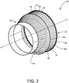
- the surface treatment assembly 60 includes a plurality of base structures 70 arranged to form a circular array 72.
- an embodiment of the surface treatment assembly 60 is arranged in a complete circular ring configured to circumferentially surround fuselage 24.
- the circular array 72 is configured to have a larger diameter than the fuselage 24 such that the circular array 72 of the surface treatment assembly 60 is able to avoid contact with the fuselage 24 and any other components that are attached to the surface as the surface treatment assembly moves along the contoured surface 48.
- alternative or additional configurations of the plurality of base structure 70 are possible, such as but not limited to semi-circular, linear, staggered, or other such configuration to produce alternative geometries of the surface treatment assembly 60.
- the surface treatment assembly 60 includes a plurality of finger structures 74 which are operably coupled to the plurality of base structures 70.
- the finger structures 74 are configured to extend away in the axial direction from the plurality of base structures 70 along an axis A-A.
- the finger structures 74 are configured to include a first phalange structure 76 and a second phalange structure 78 operably coupled to one another at a phalange joint 80.
- first phalange structure 76 and second phalange structure 78 are constructed out of a flexible material such as but not limited to, a composite, carbon fiber, flexible metal, or other known flexible material.
- each finger structure 74 is configured such that a first end 82 of the first phalange structure 76 is operably coupled to a base structure 70, and the phalange joint 80 is disposed between a second end 84 of the first phalange structure 76 and a first end 86 of the second phalange structure 78.
- the phalange joint 80 operatively couples the first phalange structure 76 to the second phalange structure 78 such that each finger structure 74 can be manipulated, adjusted or otherwise articulated in response to the topography or other surface geometry of the contoured surface 48.
- each base structure 70 is configured with a slot 88 that is formed into at least a portion of a base structure lateral surface 90. Moreover, at least a portion of the first end 82 of the first phalange structure 76 of each finger structure 74 is configured to extend into the slot 88. Additionally, in some embodiments, the first end 82 of the first phalange structure 76 is operably coupled to the base structure 70 with a base structure rotatable joint 92, such as but not limited to a ball joint. Moreover, each base structure 70 of the surface treatment assembly 60 includes a base structure actuating device 94, such as but not limited to a linear actuator, a radial actuator, or other known actuating device.
- a base structure actuating device 94 such as but not limited to a linear actuator, a radial actuator, or other known actuating device.
- the base structure actuating device 94 operably couples the first phalange structure 76 to the base structure 70 and the base structure actuating device 94 is configured to pivot or otherwise actuate the first end 82 of the first phalange structure 76 about the base structure rotatable joint 92 and within the slot 88.
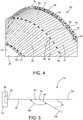
- the arrow 96 shown in FIG. 4 illustrates one non-limiting example of the lateral adjustment capability of the first phalange structure 76 within the slot 88 as the first end 82 of the first phalange structure 76 pivots or otherwise rotates about the base structure rotatable joint 92.
- each finger structure 74 is configured with a phalange joint actuator 98, such as but not limited to, a hinge actuator or other such actuating device.
- the phalange joint actuator 98 is operably coupled to the phalange joint 80, the first phalange structure 76 and the second phalange structure 78.
- the phalange joint actuator 98 is configured to adjust or otherwise manipulate the first phalange structure 76 and the second phalange structure 78 about the phalange joint 80.
- the finger structure 74 forms an actuation angle 100 between a portion of the first phalange structure 76 and the second phalange structure 78. More specifically, the actuation angle 100 is defined as the angle formed where the second end 84 of the first phalange structure 76 and the first end 86 of the second phalange structure 78 are operably coupled together by the phalange joint 80.
- the finger structure 74 is capable of being manipulated or otherwise adjusted between multiple positions.
- the finger structure 74 is manipulated between a first position 102 (i.e., first radius) and a second position 104 (i.e., second radius).
- first position 102 i.e., first radius
- second position 104 i.e., second radius
- other positions are possible.
- the actuation angle 100 formed between the first phalange structure 76 and the second phalange structure 78 can have a range between 180 degrees (i.e., finger structure 74 extended straight) and 100 degrees (i.e., second phalange structure 78 angled down from first phalange structure 76).
- an alternative actuation angle 100 range is possible for manipulating the finger structure 74 between the first position 102 and the second position 104.
- the finger structure 74 illustrated in FIGS. 3-5 is configured with the first phalange structure 76, the second phalange structure 78 and the phalange joint 80, other configurations are possible.
- an alternative configuration of the finger structure 74 includes a plurality of phalange joints 80 and three or more phalange structures (i.e., first phalange structure 76, second phalange structure 78, and a third phalange structure). Such a configuration will add additional manipulation and adjustment capabilities to each finger structure 74 of the surface treatment assembly 60.
- one non-limiting example of the surface treatment assembly 60 is configured such that the plurality of base structures 70 and finger structures 74 are arranged to form a circular array 72.
- the circular array 72 is configured such that each base structure 70 and finger structure 74 circumferentially surround the contoured surface 48 of the fuselage 24.
- each finger structure 74 is adapted to hold and position at least one surface treatment applicator head 106 such as but not limited to, an ink jet print head, a paint nozzle, an abrasion ring, a dry/cure and inspection ring, a heater, an UV emitter, and other known applicator heads.
- the surface treatment applicator head 106 is coupled to a second end 108 of the second phalange structure 78 and positioned adjacent to the contoured surface 48 of the fuselage 24.
- the surface treatment applicator head 106 is coupled to or otherwise includes an applicator rotatable joint 110, such as but not limited to, a ball joint.
- the applicator rotatable joint 110 is disposed between the second end 108 of the second phalange structure 78 and the surface treatment applicator head 106.
- the applicator rotatable joint 110 is manipulated or otherwise adjusted along with the base structure rotatable joint 92 and the phalange joint 80 to ensure that the each surface treatment applicator head 106 of the surface treatment assembly 60 maintains a normal orientation relative to the contoured surface 48 and a proper distance or dispense gap between the surface treatment applicator head 106 and the contoured surface 48.
- the surface treatment assembly 60 is made adjustable about a plurality of axes (i.e., base structure rotatable joint 92, phalange joint 80, and applicator rotatable joint 110) in order to conform with and follow the variety of surface geometries and profiles (i.e., increased/decreased diameter and convex/concave surfaces) encountered along the contoured surface 48 or the fuselage 24, or other component of the vehicle 20 ( FIG. 1 ).
- axes i.e., base structure rotatable joint 92, phalange joint 80, and applicator rotatable joint 110
- each surface treatment applicator head 106 and finger structure 74 is interchangeably configured such that the type of surface treatment applicator head 106 attached to the surface treatment assembly 60 depends on the desired surface treatment.
- the surface treatment applicator head 106 is configured as an ink jet print head used to apply a decorative livery coating on the contoured surface 48, while the surface treatment applicator head 106 is configured as a paint nozzle to apply a primer, adhesion promoter, a base coat, a clear coat layer or other such layer to the contoured surface 48.
- the surface treatment applicator head 106 attached to each finger structure 74 is configured as an abrasion ring used to clean and abrade the contoured surface 48.
- the surface treatment applicator head 106 can be configured as a heater and UV emitter to form a dry/cure and inspection ring to dry, cure and inspect the surface treatment layer 51 ( FIG. 2 ) along the contoured surface 48 of the fuselage 24.
- the surface treatment assembly 60 is configured such that the circular array 72 is adjustable with respect to the position of each finger structure 74 relative to the contoured surface 48.
- each base structure 70 and finger structure 74 is independently adjustable from one another such that the first phalange structure 76 and the second phalange structure 78 of each finger structure is adjusted to maintain the proper positioning (i.e., normal orientation and distance) of each surface treatment applicator head 106 with respect to the contoured surface 48.
- the independent actuation and adjustment of each base structure 70 and finger structure 74 enables a versatile and resilient response by the surface treatment assembly 60 to the complex geometry and contour encountered along the contoured surface 48.
- the surface treatment assembly 60 include at least one sensor 112 mounted on or otherwise coupled to each of the finger structures 74.
- the sensor 112 is coupled to or otherwise attached to the second phalange structure 78 near the second end 108. Additionally or alternatively, the sensor 112 is incorporated with the surface treatment applicator head 106. Regardless of its location, the at least one sensor 112 incorporated with each finger structure 74 is configured to scan and collect surface profile and other such data of the contoured surface 48. In some embodiments, the collected data (i.e., contoured data set) is used in to manipulate, adjust or otherwise actuate the surface treatment assembly 60.
- the sensors 112 such as but not limited to, a vision sensor (i.e., camera), a laser scanning topography and surface height sense sensor (i.e., LIDAR), and other such surface metrology sensors, are configured to scan and monitor the topography and other geometries of the contoured surface 48 and produce a data set of the contoured surface 48.
- the data set is used by the surface treatment assembly 60 to adjust and manipulate the base structures 70 and finger structures 74 to ensure that the each surface treatment applicator head 106 maintains a normal orientation and distance relative to the contoured surface 48.
- the continuous collection of surface data from the contoured surface 48, and other portions of the fuselage 24, provides improved accuracy in the actuation, manipulation, and adjustment of the surface treatment assembly 60 during the application of the surface treatment layer 51. Additionally, the use of the collected data by the surface treatment assembly 60 reduces the amount of time required to treat the contoured surface 48.
- FIG. 6 illustrates a schematic of a control and communication system 114 that is configured to operate the overhead gantry 62, and at least one surface treatment assembly 60.
- the control and communication system 114 is composed of a controller 116 and an input/output terminal 118 which is communicably coupled to the controller 116.
- the controller 116 is programmed to control the movement and other operational functions of the overhead gantry 62, and the surface treatment assembly 60.
- the surface treatment assembly 60 is attached to one or more AGVs 52 configured to move about the work area 50 ( FIG. 2 ). In such cases, the controller 116 is programmed to control movement of the AGVs 52, the surface treatment assembly 60 and any other such components.
- controller 116 is programmed to monitor and adjust the position of each base structure 70, finger structure 74, and surface treatment applicator heads 106.
- control and communication system 114 shown in FIG. 6 illustrates a single base structure 70, finger structure 74 and surface treatment applicator head 106.
- control and communication system 114 is configured to control each of the plurality of base structures 70, finger structures 74, and surface treatment applicator heads 106 included in the surface treatment assembly 60.
- the controller 116 and the input/output terminal 118 are located remotely from the work area 50 ( FIG. 2 ). As a result, communication between the controller 116, the input/output terminal 118, the surface treatment assembly 60 and other components of the control and communications system114, is established using a radio frequency network, a computer data network, a Wi-Fi data network, a cellular data network, a satellite data network, or any other known data communication network. Alternatively, the controller 116 and the input/output terminal 118 are configured to be proximally located within the work area 50 ( FIG. 2 ) and set up in a position adjacent to the surface treatment assembly 60.
- the controller 116 and the input/output terminal 118 are still configured to communicate using a radio frequency network a computer data network, a Wi-Fi data network, a cellular data network, a satellite data network or any other known communication network.
- a user of the control and communication system 114 can access the controller 116 using the input/output terminal 118.
- the input/output terminal 118 allows for commands and other instructions to be input through a keyboard, mouse, dial, button, touch screen, microphone or other known input devices.
- data and other information generated by the control and communication system 114 and the controller 116 will be output to the input/output terminal 118 through a monitor, touch screen, speaker, printer, or other known output device for the user.
- the input/output terminal 118 is communicably coupled to the controller 116 through a wired connection.
- the input/output terminal 118 is communicably coupled to the controller 116 through a wireless communication network such as Bluetooth, near-field communication, a radio frequency network, a computer data network, a Wi-Fi data network, a cellular data network, a satellite data network or any other known data communication network.
- the input/output terminal 118 is a handheld mobile device, such as a tablet computer, a smart phone device, or other such mobile device, and the handheld mobile device is wirelessly coupled to the controller 116.
- the control and communication system 114 can access the controller 116, each user having a different handheld input/output terminal 118 that is remotely located from the controller 116 and/or the surface treatment assembly 60.
- Such a configuration will allow for the flexibility in monitoring and operating the control and communication system 114 during treatment of the contoured surface 48 of the fuselage 24.
- the controller 116 of the control and communication system 114 is composed of one or more computing devices that are capable of executing a control mechanism and/or software which allows the user to direct and control the surface treatment assembly 60.
- the one or more computing devices of the controller 116 are programmed to control the movement of the overhead gantry 62, the surface treatment AGV 52, or other movement device, to move and position the at least one surface treatment assembly 60 along the contoured surface 48 of the fuselage 24.
- the one or more computing devices of the controller 116 are programmed to control the actuation and adjustment of the surface treatment assembly 60 in order to properly position the surface treatment assembly 60 relative to the contoured surface 48.
- the user is able to use the controller 116 and input/output terminal 118 to program a pattern or process for the surface treatment assembly 60 to follow while applying the surface treatment layer 51 or other such treatment along the contoured surface 48.
- the communicably coupling of the controller 116, the input/output terminal 118, and the surface treatment assembly 60 using a communication network allows for two-way communication such that commands sent by the controller 116 are received by the surface treatment assembly 60, and data collected by the surface treatment assembly 60 is sent to and received by the controller 116.
- At least one sensor 112 such as but not limited to, a vision sensor (i.e., camera), a laser scanning topography and surface height sense sensor (i.e., LIDAR), and other such surface metrology sensor, is incorporated into the surface treatment assembly 60 and communicably coupled to the controller 116 and the input/output terminal 118.
- each finger structure 74 of the surface treatment assembly 60 includes the sensor 112 configured to scan and monitor the surface topography and other geometries of the contoured surface 48.
- each surface treatment applicator head 106 is configured to include the sensor 112. The data collected by the sensors 112 is transmitted to and utilized by the controller 116.
- controller 116 is programmed to store, analyze and extract information from the data collected by the plurality of sensors 112 and use the extracted information to control and adjust the surface treatment assembly 60.
- control and communication system 114 is configured to use the extracted information to independently control and adjust each base structure 70, finger structure 74, and surface treatment applicator head 106 of the surface treatment assembly 60.
- the at least one sensor 112 and the controller 116 are operably coupled which enables them to work together to collect data on the contoured surface 48 such as but not limited to, detect a change in the radius (i.e., increase or decrease) of the fuselage 24, collect imaging and vision data of the contoured surface 48, provide a topographical map and surface profile of the contoured surface 48, provide positioning and location data of the surface treatment assembly 60, and provide any other such surface data collected by the at least one sensor 112.
- the collected data is then transmitted by the at least one sensor 112 and received by the controller 116 such that the control mechanism and/or software of the controller 116 is able to utilize the data to make adjustments to the control and operation of the overhead gantry 62, the surface treatment assembly 60, individual base structures 70, finger structures, surface treatment applicator heads 106, and other such components. Additionally, the user is able to view the data collected by the at least one sensor 112 on the input/output terminal 118, and if necessary, make adjustments to the control commands sent from the controller 116 to the overhead gantry 62, the surface treatment assembly 60, individual base structures 70, finger structures 74, surface treatment applicator heads 106, and other such components.
- control and communication system 114 is capable of making real time adjustments to the overhead gantry 62, the surface treatment assembly 60, individual base structures 70, finger structures 74, surface treatment applicator heads 106 and other such components through the two-way communication link established between the surface treatment assembly 60 and the control and communication system 114.
- a flowchart illustrating an exemplary surface treatment method or process 120 of treating a contoured surface 48 with a surface treatment assembly 60 is illustrated.
- a structure having a contoured surface 48 such as the fuselage 24
- the fuselage 24 is transported into the work area 50 by one or more AGVs 52 and delivered to the vehicle nose support structure 54, the vehicle central support structure 56, or other support structures.
- the fuselage 24 is supported by the nose and vehicle central support structures 54, 56, the one or more AGVs 52 and any other support structures that may be needed.
- the application of the surface treatment layer 51 includes the removal of any protective or previously applied coatings on the contoured surface 48, masking certain areas of the contoured surface 48 not to be treated, abrading, cleaning, and drying the contoured surface 48, applying a surface protective coating, an adhesion promoting coating, a primer coating, a basecoat coating, a sol-gel coating, a top layer coating, a decorative livery coating, a clear coating, and/or other protective coatings and/or preparation treatments.
- a surface protective coating an adhesion promoting coating, a primer coating, a basecoat coating, a sol-gel coating, a top layer coating, a decorative livery coating, a clear coating, and/or other protective coatings and/or preparation treatments.
- at least one surface treatment assembly 60 is attached or otherwise coupled to the overhead gantry 62 and positioned within the work area 50.
- the surface treatment assembly 60 adjusted and aligned along the contoured surface 48 of the fuselage 24.
- at least one sensor 112 attached to the surface treatment assembly 60 is configured to scan and collect the surface topography data of the contoured surface 48.
- the surface topography data or contoured data set is then transmitted to and received by the controller 116 of the control and communication system 114 and utilized to adjust the command and control parameters sent from the controller 116 to the surface treatment assembly 60.
- an adjustment check is performed prior to the application of the surface treatment layer 51 along the contoured surface 48 to confirm that each base structure, 70, finger structure 74, and surface treatment applicator head 106 of the surface treatment assembly 60 are properly adjusted and aligned relative to the contoured surface 48.
- the adjustment check includes confirmation of the proper distance or gap between the contoured surface 48 and each surface treatment applicator head 106. Additionally the adjustment check confirms that each surface treatment applicator head 106 is in a normal and orthogonal orientation relative to the contoured surface 48.
- each surface treatment applicator head 106 of the surface treatment assembly 60 Failure to properly adjust and align each surface treatment applicator head 106 of the surface treatment assembly 60 relative to the contoured surface 48 will result in a defective surface treatment such as, a non-uniform application of the surface treatment layer 51, or other such surface treatment defect. Therefore, if the inspection fails the set of pre-determined adjustment criteria which are input into and stored in the controller 116, then the surface treatment assembly 60 continues adjustment of the surface treatment assembly 60 to correct any adjustment and/or alignment errors. In some embodiments, the operator or other user will be notified of the adjustment errors and instructed to make the necessary adjustment and alignment of the surface treatment assembly 60.
- each of the finger structures 74 of the surface treatment assembly 60 are interchangeably coupled to at least one surface treatment applicator head 106 such as but not limited to, an abrasion ring, a paint nozzle, an ink jet print head, a dry/cure and inspection ring, a heater, an UV emitter, and other known applicator heads.
- the surface treatment applicator head 106 is chosen based on the desired surface treatment of the contoured surface 48.
- the surface treatment assembly 60 generally starts the application of the surface treatment layer 51 on the contoured surface 48 at the tail section 28 of the vehicle 20 and moves along the fuselage 24 towards the nose portion 46.
- the surface treatment assembly 60 is aligned and adjusted at an intermediate location between the tail section 28 and the nose portion 46 and the surface treatment assembly 60 applies the surface treatment layer 51 along the contoured surface 48 where directed.
- the surface treatment assembly 60 continues moving along the contoured surface 48, and at least one sensor 112 continues to scan and collect data of the contoured surface 48 topography.
- the data collected by the sensor 112 is utilized by the controller 116 to make real-time adjustments to the surface treatment assembly 60 as it moves along the contoured surface 48.
- each base structure 70, finger structure 74, and surface treatment applicator head 106 of the surface treatment assembly 60 is continuously adjusted to maintain a normal and orthogonal orientation between the surface treatment applicator head 106 and the contoured surface 48.
- the controller 116 continues to analyze the surface topography data collected by the at least one sensor 112 as the surface treatment assembly 60 continues to move along the contoured surface 48 of the fuselage 24.
- the control and communication system 114 which includes the controller 116, will continuously perform adjustment checks to confirm that each base structure 70, finger structure 74 and surface treatment applicator head 106 of the surface treatment assembly 60 is properly adjusted, aligned, and orientated with the contoured surface 48.
- the controller 116 will transmit an adjustment control signal to the surface treatment assembly 60 to adjust or readjust each base structure 70, finger structure 74, and surface treatment applicator head 106 of the surface treatment assembly 60.
- a next block 134 if it is determined that one or more base structure 70, finger structure 74, and/or surface treatment applicator head 106 remains out of alignment, then the surface treatment assembly 60 stops moving along the contoured surface 48 of the fuselage 24 in order to perform the readjustment.
- the method 120 of treating the contoured surface 48 returns to block 132 for readjustment of each base structure 70, finger structure 74 and surface treatment applicator head 106 of the surface treatment assembly 60
- the surface treatment assembly 60 moves along the contoured surface 48 at a slower pace in order to perform the readjustment and realignment of each base structure 70, finger structure 74 and surface treatment applicator head 106 on the fly.
- the controller 116 makes a determination of whether another surface treatment is required.
- the method 120 of treating a contoured surface 48 returns to block 124 and the appropriate surface treatment applicator head 106 is coupled to each finger structure 74, and the surface treatment assembly 60 is positioned at the designated starting position (i.e., the nose portion 46, the tail section 28 or alternative pre-determined starting point) and prepares for the next surface treatment along the contoured surface 48 of the fuselage 24.
- the same surface treatment assembly 60 is used for the subsequent surface treatment and the surface treatment applicator heads 106 are exchanged depending on the desired surface treatment.
- subsequent surface treatments are performed to the contoured surface 48 using one or more additional surface treatment assemblies 60 configured with the desired surface treatment applicator heads 106.
- a surface treatment assembly for treating a contoured surface comprising:
- each base structure of the plurality of base structures further comprises a slot and a ball joint pivotally coupled with the first phalange structure first end, and manipulation of the base structure actuator causes the first phalange structure of each finger structure to pivot about the ball joint within the slot.
- A5 The surface treatment assembly of any of clauses A1 to A4, further comprising at least one sensor coupled to each finger structure of the surface treatment array configured to detect an existing shape of a contoured surface and generate a contoured data set, a controller communicably coupled to the at least one sensor, the base structure actuator and the phalange joint actuator, wherein the controller is programmed to receive a signal from the at least one sensor and control the base structure actuator and the phalange joint actuator to manipulate the surface treatment array based on the contoured data set.
- a surface treatment assembly for treating a contoured surface comprising:
- each base structure of the plurality of base structures further comprises a slot and a ball joint pivotally coupled with the first phalange structure first end, and configured such that manipulation of the base structure actuator causes the first phalange structure of each finger structure to pivot about the ball joint within the slot.
- Apparatus comprising a contoured surface and a surface treatment assembly for treating the contoured surface, the surface treatment assembly comprising:
- each base structure of the plurality of base structures further comprises a slot and a ball joint pivotally coupled with the first phalange structure first end, and manipulation of the base structure actuator causes the first phalange structure of each finger structure to pivot about the ball joint within the slot.
- a surface treatment system for treating an exterior surface of an airplane comprising:
- each base structure of the plurality of base structures further comprises a slot and a ball joint pivotally coupled with the first phalange structure first end, and manipulation of the base structure actuator causes the first phalange structure of each finger structure to pivot about the ball joint within the slot.
- a surface treatment system for treating an exterior surface of an airplane comprising:
- each base structure of the plurality of base structures further comprises a slot and a ball joint pivotally coupled with the first phalange structure first end, and manipulation of the base structure actuator causes the first phalange structure of each finger structure to pivot about the ball joint within the slot.
- Apparatus comprising an exterior surface of an airplane and a surface treatment system for treating the exterior surface of the airplane, the surface treatment system comprising:
- each base structure of the plurality of base structures further comprises a slot and a ball joint pivotally coupled with the first phalange structure first end, and manipulation of the base structure actuator causes the first phalange structure of each finger structure to pivot about the ball joint within the slot.
- a method of treating a contoured surface with a surface treatment assembly comprising:
- manipulating the base structure actuator and the phalange joint actuator includes coordinating activation of the base structure actuator and the phalange joint actuator and adjusting each finger structure of the surface treatment array between a first contoured shape and a second contoured shape.
- adjusting the surface treatment array between the first contoured shape and the second contoured shape includes adjusting the surface treatment array between a first radius and a second radius.
- adjusting the surface treatment array between the first contoured shape and the second contoured shape includes adjusting the surface treatment array between a first radius and a second radius.
Landscapes
- Engineering & Computer Science (AREA)
- Manufacturing & Machinery (AREA)
- Application Of Or Painting With Fluid Materials (AREA)
- Coating Apparatus (AREA)
Abstract
Description
- The present disclosure relates generally to automated surface treatment assemblies and methods for treating a surface, and more specifically to an automated adjustable surface treatment assembly system and method for treating a contoured surface.
- Treating and coating structural surfaces of machines, such as commercial aircraft, is a long and extensive process. Surface treatment often requires coating a structural surface that includes a variety of large contoured surfaces. Furthermore, coating the structural surfaces includes applying multiple layers of coatings for engineering properties, as well as to apply a decorative livery. The decorative livery is applied using a complex process which requires a series of masking operations followed by applying colored paints or coatings where they are needed. These masking and painting operations are serially repeated until the exterior surface treatment is completed. Performing these processes on large areas with a variety of contoured surfaces, therefore, requires a significant amount of time and resources.
- In accordance with one aspect of the present disclosure a surface treatment assembly for treating a contoured surface is disclosed. The surface treatment assembly includes a surface treatment array formed from a plurality of base structures and each base structure being operably coupled to a first phalange structure and a first phalange structure first end. The surface treatment assembly may further include a second phalange structure operatively coupled to each first phalange structure and a phalange joint disposed between each first phalange structure and each second phalange structure. The phalange joint is operably coupled to a first phalange structure second end and a second phalange structure first end, thereby forming a finger structure. Moreover, at least one applicator head is coupled to a second phalange structure second end of each finger structure and each of the at least one applicator head being arranged to treat the contoured surface. The surface treatment assembly further includes a base structure actuator operatively coupled to and manipulates the first phalange structure of each finger structure. Furthermore, a phalange joint actuator is operatively coupled to and manipulates the second phalange structure of each finger structure. The base structure actuator and the phalange joint actuator adjusts the surface treatment array relative to the contoured surface.
- In accordance with another aspect of the present disclosure, a method of treating a contoured surface with a surface treatment assembly is disclosed. The method includes forming a surface treatment array from a plurality of base structures and coupling a finger structure to each base structure of the plurality of base structures. The finger structure including a first phalange structure, a second phalange structure and a phalange joint disposed therebetween. The method further includes coupling at least one applicator head to the second phalange structure of each finger structure, and each of the at least one applicator head being arranged to apply a surface treatment layer to the contoured surface. The method further includes, coupling a base structure actuator to each base structure and a phalange joint actuator to each phalange joint, and manipulating each of the base structure actuators and each of the phalange joint actuators such that the surface treatment array is adjusted relative to the contoured surface.
- In accordance with yet another aspect of the present disclosure, a surface treatment system for treating an exterior surface of an airplane is disclosed. The surface treatment system includes a circular surface treatment array formed from a plurality of base structures, each base structure being operably coupled to a first phalange structure at a first phalange structure first end. The surface treatment system may further include a second phalange structure operatively coupled to each first phalange structure and a phalange joint disposed between each first phalange structure and each second phalange structure. The phalange joint is operably coupled to a first phalange structure second end and a second phalange structure first end, thereby forming a finger structure. Moreover, at least one applicator head is coupled to a second phalange structure second end of each finger structure and each of the at least one applicator head treats a contoured surface along the exterior surface of the airplane. The surface treatment assembly further includes a base structure actuator operatively coupled to and manipulates the first phalange structure of each finger structure. Furthermore, a phalange joint actuator is operatively coupled to and manipulates the second phalange structure of each finger structure. At least one sensor is coupled to each finger structure of the circular surface treatment array and the at least one sensor detects an existing shape of the contoured surface and may generate a contoured data set. The surface treatment system further includes a controller communicably coupled to the at least one sensor, the base structure actuator, and the phalange joint actuator. The controller being programmed to receive a signal from the at least one sensor and to control the base structure actuator and the phalange joint actuator to manipulate the circular surface treatment array based on the contoured data set of the exterior surface of the airplane.
- The features, functions, and advantages disclosed herein can be achieved independently in various embodiments or may be combined in yet other embodiments, the details of which may be better appreciated with reference to the following description and drawings.
-
-
FIG. 1 is a perspective view of an exemplary vehicle constructed in accordance with the present disclosure; -
FIG. 2 is a perspective view of an exemplary contoured surface and surface treatment assembly positioned in a work area, in accordance with the present disclosure; -
FIG. 3 is a perspective view of an exemplary surface treatment assembly, in accordance with the present disclosure; -
FIG. 4 is an enlarged perspective view of the surface treatment assembly ofFIG. 3 , in accordance with the present disclosure; -
FIG. 5 is a schematic view of an exemplary finger structure of the surface treatment assembly ofFIGS. 3 and4 , in accordance with the present disclosure; -
FIG. 6 is a schematic view of an exemplary control and communication system in accordance with the present disclosure; and -
FIG. 7 is a flowchart illustrating an exemplary method of treating a contoured surface with the surface treatment assembly in accordance with the present disclosure. - It should be understood that the drawings are not necessarily to scale, and that the disclosed embodiments are illustrated diagrammatically, schematically, and in some cases in partial views. In certain instances, details which are not necessary for an understanding of the disclosed methods and apparatuses or which render other details difficult to perceive may have been omitted. It should be further understood that the following detailed description is merely exemplary and not intended to be limiting in its application or uses. As such, although the present disclosure is for purposes of explanatory convenience only depicted and described in illustrative embodiments, the disclosure may be implemented in numerous other embodiments, and within various systems and environments not shown or described herein.
- The following detailed description is intended to provide both methods and devices for carrying out the disclosure. Actual scope of the disclosure is as defined by the appended claims.
- Referring to
FIG. 1 , avehicle 20 is illustrated. One non-limiting example of thevehicle 20 is that of an aircraft; however the present disclosure applies to other types of vehicles and machines as well. As illustrated, thevehicle 20 is configured with anairframe 22 which includes afuselage 24,wings 26, and atail section 28. Additionally, one ormore propulsion units 30 are coupled to eachwing 26 in order to propel thevehicle 20 in a direction of travel. Furthermore, eachwing 26 is fixedly attached to thefuselage 24 and thepropulsion units 30 are attached to an underside surface of thewing 26, however other attachment locations of thepropulsion units 30 are possible. In some embodiments, eachwing 26 is positioned at a substantially centered position along thefuselage 24, and eachwing 26 is configured to include a plurality offlaps 32, leadingedge devices 34, and peripheral edge devices 36 (i.e., winglets). Moreover, during operation of thevehicle 20, theflaps 32, leadingedge devices 34 andperipheral edge devices 36 are capable of being adjusted in a plurality of positions in order to control and stabilize thevehicle 20. For example, theflaps 32 and leadingedge devices 34 are adjustable in several different positions to produce the desired lift characteristics of thewings 26. Additionally, thetail section 28 of theairframe 22 includes components which provide other stability and maneuverability functions of thevehicle 20, such as anelevator 38, arudder 40, avertical stabilizer fin 42, and ahorizontal stabilizer 44. -
FIG. 2 illustrates one non-limiting example of thefuselage 24 portion of thevehicle 20, with thewings 26,rudder 40,vertical stabilizer fin 42horizontal stabilizer 44, and other components unattached or removed from thefuselage 24. Generally, thefuselage 24 and other components of thevehicle 20 are constructed out of aluminum, aluminum alloy, titanium, carbon composite, or other known material. Moreover, thefuselage 24 forms a tubular structure of thevehicle 20, which includes anose portion 46 designated as the front of thefuselage 24 and thetail section 28 designated as the rear of thefuselage 24. The outer surface of thefuselage 24 has changing dimensions and topography along the length of thefuselage 24 between thenose portion 46 and thetail section 28. As a result, thefuselage 24 is often described as having acontoured surface 48 or profile. In one embodiment, thecontoured surface 48 includes a variety of surface profiles formed by a series of changing surface geometries of thefuselage 24 andother vehicle 20 components. For example, moving along thefuselage 24 from thenose portion 46 to thetail section 28, thecontoured surface 48 exhibits changing geometries and profiles such as but not limited to, an increase in diameter of thefuselage 24, a decrease in diameter of thefuselage 24, a convex surface, a concave surface, or other such surface geometries, and profiles, or combinations thereof. - During
vehicle 20 manufacture and/or servicing, thefuselage 24, and other vehicle components, is positioned within awork area 50 and prepared for one or more manufacturing and/or scheduled service steps. In some embodiments, the manufacturing and/or servicing of thevehicle 20 includes applying asurface treatment layer 51 along the contouredsurface 48 of thefuselage 24. Generally, the application of thesurface treatment layer 51 along the contouredsurface 48 includes one or more of cleaning, abrading, priming, painting, protecting, curing, inspecting, repairing, or other known surface treatments of the contouredsurface 48. Moreover, one non-limiting example of thesurface treatment layer 51 includes the application of decorative livery coatings, which not only provide surface protection against the harsh environmental conditions encountered by thevehicle 20, but also create a decorative design on thefuselage 24 which helps to identify and distinguish the onevehicle 20 from another. Additionally, in some embodiments, thesurface treatment layer 51 is composed of multiple layers such as, primer coatings, adhesion promoters, base coats, clear coats, livery coats, and other surface treatment layers are applied to the contouredsurface 48. - As further illustrated in
FIG. 2 , thevehicle 20 is prepared for surface treatments by positioning thefuselage 24 within thework area 50 prior to attaching, or otherwise coupling, each wing 26 (FIG. 1 ), rudder 40 (FIG. 1 ), vertical stabilizer fin 42 (FIG. 1 ), horizontal stabilizer 44 (FIG. 1 ), and other components to thevehicle 20. However, in alternative embodiments, such as but not limited to, during service or maintenance of thevehicle 20, surface treatment of the contouredsurface 48 is possible on a fully assembledvehicle 20 with the wings 26 (FIG. 1 ), rudder 40 (FIG. 1 ), vertical stabilizer fin 42 (FIG. 1 ), horizontal stabilizer 44 (FIG. 1 ) and other components already attached . For example, in some instances, the exterior surface of thevehicle 20 is damaged during operation and the contouredsurface 48 requires repair to fix the damage. As a result, the fully assembledvehicle 20 is positioned within thework area 50 and prepared for one or more surface treatments. - Prior to the start of the surface treatment, the
fuselage 24 is delivered to thework area 50 by a plurality of automated guided vehicles 52 (AGVs). TheAGVs 52 are positioned along the underside of thefuselage 24 to provide adequate support to thevehicle 20 and configured to move thefuselage 24 into position. WhileFIG. 2 shows the use of fourAGVs 52, other numbers of AGVs 52 (i.e., fewer or greater) are certainly possible. Once theAGVs 52 move thefuselage 24 into thework area 50 one or more structures are positioned along the underside of thefuselage 24 to provide support during the surface treatment. In some embodiments, a vehiclenose support structure 54 is located on the underside of thenose portion 46 of thefuselage 24 and at least one vehiclecentral support structure 56 is positioned underneath of the central portion of thefuselage 24. Additionally, while the vehiclenose support structure 54 and the vehiclecentral support structure 56 are shown inFIG. 2 , one or more additional support structures can be placed in other places along thefuselage 24 which require support, such as but not limited to, underneath thetail section 28 or anywhere in between the vehiclenose support structure 54 and vehiclecentral support structure 56. - In one non-limiting embodiment, the nose and vehicle
central support structures floor 57 of thework area 50 by a set of vehicle support structure rails 58. The nose and vehiclecentral support structures fuselage 24 to ensure thefuselage 24, or other component of thevehicle 20, is properly supported. Furthermore, the nose and vehiclecentral support structures AGVs 52. As a result, theAGVs 52 are capable of being used along with the nose and vehiclecentral support structures fuselage 24, or other component of thevehicle 20, during surface treatment. WhileFIG. 2 illustrates the use ofAGVs 52 and the nose and vehiclecentral support structures fuselage 24 and other components of thevehicle 20, it will be known to those skilled in the art that other methods of positioning, supporting and transporting thefuselage 24 andother vehicle 20 components are possible. - As further illustrated in
FIG. 2 , thework area 50 is equipped with at least onesurface treatment assembly 60 that is configured to apply or otherwise treat the contouredsurface 48 of thevehicle 20 with asurface treatment layer 51. In some embodiments, thesurface treatment assembly 60 is attached to anoverhead gantry 62, which is configured to provide support and movement of thesurface treatment assembly 60 within thework area 50. In one non-limiting example, theoverhead gantry 62 is attached to anoverhead gantry structure 63 that runs the length L-L of thework area 50 that houses thefuselage 24 or other components of thevehicle 20 during surface treatment. Theoverhead gantry 62 is configured to move thesurface treatment assembly 60 along theoverhead gantry structure 63 as it treats the contouredsurface 48 of thevehicle 20. Furthermore, in one non-limiting example thesurface treatment assembly 60 includes anattachment pillar 64 which couples thesurface treatment assembly 60 to theoverhead gantry 62. - Additionally or alternatively, the
surface treatment assembly 60 is mounted on a surface treatment assembly automated guided vehicle (AGV) 66, similar to theAGVs 52 used to move thefuselage 24 in and out of thework area 50. The surfacetreatment assembly AGV 66 is configured to move along the length L-L of thefloor 57 of thework area 50 as thesurface treatment assembly 60 treats the contouredsurface 48 of thevehicle 20. In one embodiment, the surfacetreatment assembly AGV 66 is coupled to a set of surface treatment AGV rails 68, which are positioned laterally alongside thefuselage 24 and configured to run along the length L-L of thefloor 57 of thework area 50. Furthermore, some embodiments include two sets of the surface treatment AGV rails 68 that are spaced apart within thework area 50 such that thefuselage 24 is capable of being positioned and substantially centered between the two sets of the surface treatment AGV rails 68. As a result, one or moresurface treatment assemblies 60 are capable of being positioned on each side of thefuselage 24 during surface treatment of the contouredsurface 48. In an alternative embodiment, the surfacetreatment assembly AGV 66 is configured with a set of wheels or other ground engaging elements that do not require being mounted on the surface treatment AGV rails 68. As a result, the surfacetreatment assembly AGV 66 travels along thefloor 57 of thework area 50 on the set of wheels or other ground engaging elements while thesurface treatment assembly 60 treats the contouredsurface 48 of thevehicle 20. - In some embodiments, a plurality of
surface treatment assemblies 60 are used for surface treatment of the contouredsurface 48 such that one or moresurface treatment assemblies 60 are mounted on one or moreoverhead gantries 62, one or more surface treatmentsupport assembly AGVs 66 or a combination thereof. Theoverhead gantry 62 and/or the surfacetreatment assembly AGV 66 are arranged around thefuselage 24 to position each of thesurface treatment assemblies 60 adjacent to the contouredsurface 48. As a result, the plurality ofsurface treatment assemblies 60 mounted on theoverhead gantry 62 and/or surface treatmentsupport assembly AGVs 66 are arranged to circumferentially surround thetubular fuselage 24, or other such surface geometry of thefuselage 24. As a result, thesurface treatment layer 51, or other such surface treatment is applied to the entire circumference of the contouredsurface 48 as the plurality of surface treatment assemblies move along thefuselage 24. - Referring now to
FIGS. 3-4 , one non-limiting embodiment of thesurface treatment assembly 60 illustrated. In one non-limiting example, thesurface treatment assembly 60 includes a plurality ofbase structures 70 arranged to form acircular array 72. As shown inFIG. 3 , an embodiment of thesurface treatment assembly 60 is arranged in a complete circular ring configured to circumferentiallysurround fuselage 24. Moreover, thecircular array 72 is configured to have a larger diameter than thefuselage 24 such that thecircular array 72 of thesurface treatment assembly 60 is able to avoid contact with thefuselage 24 and any other components that are attached to the surface as the surface treatment assembly moves along the contouredsurface 48. However, it will be understood that alternative or additional configurations of the plurality ofbase structure 70 are possible, such as but not limited to semi-circular, linear, staggered, or other such configuration to produce alternative geometries of thesurface treatment assembly 60. - Additionally, the
surface treatment assembly 60 includes a plurality offinger structures 74 which are operably coupled to the plurality ofbase structures 70. In some embodiments, thefinger structures 74 are configured to extend away in the axial direction from the plurality ofbase structures 70 along an axis A-A. In one non-limiting example, thefinger structures 74 are configured to include afirst phalange structure 76 and asecond phalange structure 78 operably coupled to one another at a phalange joint 80. As a result, manipulation of thefinger structure 74 causes movement of thefirst phalange structure 76 andsecond phalange structure 78 about the phalange joint 80 to adduct (i.e., extend or move away from) and abduct (i.e., bend or move towards), or other such movement of each finger structure relative to the axis A-A. Moreover, in some embodiments, thefirst phalange structure 76 and thesecond phalange structure 78 are constructed out of a flexible material such as but not limited to, a composite, carbon fiber, flexible metal, or other known flexible material. Furthermore, eachfinger structure 74 is configured such that afirst end 82 of thefirst phalange structure 76 is operably coupled to abase structure 70, and the phalange joint 80 is disposed between asecond end 84 of thefirst phalange structure 76 and afirst end 86 of thesecond phalange structure 78. As a result, the phalange joint 80 operatively couples thefirst phalange structure 76 to thesecond phalange structure 78 such that eachfinger structure 74 can be manipulated, adjusted or otherwise articulated in response to the topography or other surface geometry of the contouredsurface 48. - As further illustrated in
FIGS. 3 and4 , eachbase structure 70 is configured with aslot 88 that is formed into at least a portion of a base structurelateral surface 90. Moreover, at least a portion of thefirst end 82 of thefirst phalange structure 76 of eachfinger structure 74 is configured to extend into theslot 88. Additionally, in some embodiments, thefirst end 82 of thefirst phalange structure 76 is operably coupled to thebase structure 70 with a base structure rotatable joint 92, such as but not limited to a ball joint. Moreover, eachbase structure 70 of thesurface treatment assembly 60 includes a basestructure actuating device 94, such as but not limited to a linear actuator, a radial actuator, or other known actuating device. The basestructure actuating device 94 operably couples thefirst phalange structure 76 to thebase structure 70 and the basestructure actuating device 94 is configured to pivot or otherwise actuate thefirst end 82 of thefirst phalange structure 76 about the base structure rotatable joint 92 and within theslot 88. For example, thearrow 96 shown inFIG. 4 illustrates one non-limiting example of the lateral adjustment capability of thefirst phalange structure 76 within theslot 88 as thefirst end 82 of thefirst phalange structure 76 pivots or otherwise rotates about the base structure rotatable joint 92. In some embodiments, eachfinger structure 74 is configured with a phalangejoint actuator 98, such as but not limited to, a hinge actuator or other such actuating device. The phalangejoint actuator 98 is operably coupled to the phalange joint 80, thefirst phalange structure 76 and thesecond phalange structure 78. The phalangejoint actuator 98 is configured to adjust or otherwise manipulate thefirst phalange structure 76 and thesecond phalange structure 78 about the phalange joint 80. In one non-limiting example illustrated inFIG. 5 , thefinger structure 74 forms anactuation angle 100 between a portion of thefirst phalange structure 76 and thesecond phalange structure 78. More specifically, theactuation angle 100 is defined as the angle formed where thesecond end 84 of thefirst phalange structure 76 and thefirst end 86 of thesecond phalange structure 78 are operably coupled together by the phalange joint 80. For example, thefinger structure 74 is capable of being manipulated or otherwise adjusted between multiple positions. In one non-limiting example, thefinger structure 74 is manipulated between a first position 102 (i.e., first radius) and a second position 104 (i.e., second radius). However, other positions are possible. During manipulation of thefinger structure 74, theactuation angle 100 formed between thefirst phalange structure 76 and thesecond phalange structure 78 can have a range between 180 degrees (i.e.,finger structure 74 extended straight) and 100 degrees (i.e.,second phalange structure 78 angled down from first phalange structure 76). However, it will be understood that analternative actuation angle 100 range is possible for manipulating thefinger structure 74 between thefirst position 102 and thesecond position 104. Furthermore, while thefinger structure 74 illustrated inFIGS. 3-5 is configured with thefirst phalange structure 76, thesecond phalange structure 78 and the phalange joint 80, other configurations are possible. For example, an alternative configuration of thefinger structure 74 includes a plurality of phalange joints 80 and three or more phalange structures (i.e.,first phalange structure 76,second phalange structure 78, and a third phalange structure). Such a configuration will add additional manipulation and adjustment capabilities to eachfinger structure 74 of thesurface treatment assembly 60. - Referring back to
FIGS. 3 and4 , one non-limiting example of thesurface treatment assembly 60 is configured such that the plurality ofbase structures 70 andfinger structures 74 are arranged to form acircular array 72. In some embodiments, thecircular array 72 is configured such that eachbase structure 70 andfinger structure 74 circumferentially surround the contouredsurface 48 of thefuselage 24. Moreover, eachfinger structure 74 is adapted to hold and position at least one surfacetreatment applicator head 106 such as but not limited to, an ink jet print head, a paint nozzle, an abrasion ring, a dry/cure and inspection ring, a heater, an UV emitter, and other known applicator heads. As further illustrated inFIGS 3 and4 , the surfacetreatment applicator head 106 is coupled to a second end 108 of thesecond phalange structure 78 and positioned adjacent to the contouredsurface 48 of thefuselage 24. In some embodiments, the surfacetreatment applicator head 106 is coupled to or otherwise includes an applicator rotatable joint 110, such as but not limited to, a ball joint. The applicator rotatable joint 110 is disposed between the second end 108 of thesecond phalange structure 78 and the surfacetreatment applicator head 106. Moreover, the applicator rotatable joint 110 is manipulated or otherwise adjusted along with the base structure rotatable joint 92 and the phalange joint 80 to ensure that the each surfacetreatment applicator head 106 of thesurface treatment assembly 60 maintains a normal orientation relative to the contouredsurface 48 and a proper distance or dispense gap between the surfacetreatment applicator head 106 and the contouredsurface 48. As a result, thesurface treatment assembly 60 is made adjustable about a plurality of axes (i.e., base structure rotatable joint 92, phalange joint 80, and applicator rotatable joint 110) in order to conform with and follow the variety of surface geometries and profiles (i.e., increased/decreased diameter and convex/concave surfaces) encountered along the contouredsurface 48 or thefuselage 24, or other component of the vehicle 20 (FIG. 1 ). - Furthermore, in some embodiments, each surface
treatment applicator head 106 andfinger structure 74 is interchangeably configured such that the type of surfacetreatment applicator head 106 attached to thesurface treatment assembly 60 depends on the desired surface treatment. For example, the surfacetreatment applicator head 106 is configured as an ink jet print head used to apply a decorative livery coating on the contouredsurface 48, while the surfacetreatment applicator head 106 is configured as a paint nozzle to apply a primer, adhesion promoter, a base coat, a clear coat layer or other such layer to the contouredsurface 48. Alternatively, the surfacetreatment applicator head 106 attached to eachfinger structure 74 is configured as an abrasion ring used to clean and abrade the contouredsurface 48. In yet another embodiment, the surfacetreatment applicator head 106 can be configured as a heater and UV emitter to form a dry/cure and inspection ring to dry, cure and inspect the surface treatment layer 51 (FIG. 2 ) along the contouredsurface 48 of thefuselage 24. - In some embodiments, the
surface treatment assembly 60 is configured such that thecircular array 72 is adjustable with respect to the position of eachfinger structure 74 relative to the contouredsurface 48. For example, eachbase structure 70 andfinger structure 74 is independently adjustable from one another such that thefirst phalange structure 76 and thesecond phalange structure 78 of each finger structure is adjusted to maintain the proper positioning (i.e., normal orientation and distance) of each surfacetreatment applicator head 106 with respect to the contouredsurface 48. Moreover, the independent actuation and adjustment of eachbase structure 70 andfinger structure 74 enables a versatile and resilient response by thesurface treatment assembly 60 to the complex geometry and contour encountered along the contouredsurface 48. - As further shown in
FIG. 4 , some embodiments of thesurface treatment assembly 60 include at least onesensor 112 mounted on or otherwise coupled to each of thefinger structures 74. In one non-limiting example thesensor 112 is coupled to or otherwise attached to thesecond phalange structure 78 near the second end 108. Additionally or alternatively, thesensor 112 is incorporated with the surfacetreatment applicator head 106. Regardless of its location, the at least onesensor 112 incorporated with eachfinger structure 74 is configured to scan and collect surface profile and other such data of the contouredsurface 48. In some embodiments, the collected data (i.e., contoured data set) is used in to manipulate, adjust or otherwise actuate thesurface treatment assembly 60. Furthermore, thesensors 112 such as but not limited to, a vision sensor (i.e., camera), a laser scanning topography and surface height sense sensor (i.e., LIDAR), and other such surface metrology sensors, are configured to scan and monitor the topography and other geometries of the contouredsurface 48 and produce a data set of the contouredsurface 48. In some embodiments, the data set is used by thesurface treatment assembly 60 to adjust and manipulate thebase structures 70 andfinger structures 74 to ensure that the each surfacetreatment applicator head 106 maintains a normal orientation and distance relative to the contouredsurface 48. Moreover, the continuous collection of surface data from the contouredsurface 48, and other portions of thefuselage 24, provides improved accuracy in the actuation, manipulation, and adjustment of thesurface treatment assembly 60 during the application of thesurface treatment layer 51. Additionally, the use of the collected data by thesurface treatment assembly 60 reduces the amount of time required to treat the contouredsurface 48. -
FIG. 6 , with continued reference toFIGS. 2-5 , illustrates a schematic of a control andcommunication system 114 that is configured to operate theoverhead gantry 62, and at least onesurface treatment assembly 60. The control andcommunication system 114 is composed of acontroller 116 and an input/output terminal 118 which is communicably coupled to thecontroller 116. Furthermore, in some embodiments, thecontroller 116 is programmed to control the movement and other operational functions of theoverhead gantry 62, and thesurface treatment assembly 60. Additionally or alternatively, thesurface treatment assembly 60 is attached to one or more AGVs 52 configured to move about the work area 50 (FIG. 2 ). In such cases, thecontroller 116 is programmed to control movement of theAGVs 52, thesurface treatment assembly 60 and any other such components. Furthermore, thecontroller 116 is programmed to monitor and adjust the position of eachbase structure 70,finger structure 74, and surface treatment applicator heads 106. For simplicity, the control andcommunication system 114 shown inFIG. 6 illustrates asingle base structure 70,finger structure 74 and surfacetreatment applicator head 106. However, it will be understood that the control andcommunication system 114 is configured to control each of the plurality ofbase structures 70,finger structures 74, and surface treatment applicator heads 106 included in thesurface treatment assembly 60. - In some embodiments, the
controller 116 and the input/output terminal 118 are located remotely from the work area 50 (FIG. 2 ). As a result, communication between thecontroller 116, the input/output terminal 118, thesurface treatment assembly 60 and other components of the control and communications system114, is established using a radio frequency network, a computer data network, a Wi-Fi data network, a cellular data network, a satellite data network, or any other known data communication network. Alternatively, thecontroller 116 and the input/output terminal 118 are configured to be proximally located within the work area 50 (FIG. 2 ) and set up in a position adjacent to thesurface treatment assembly 60. In the proximally located configuration, thecontroller 116 and the input/output terminal 118 are still configured to communicate using a radio frequency network a computer data network, a Wi-Fi data network, a cellular data network, a satellite data network or any other known communication network. - A user of the control and
communication system 114, such as an operator, a supervisor, or other interested personnel, can access thecontroller 116 using the input/output terminal 118. In some embodiments, the input/output terminal 118 allows for commands and other instructions to be input through a keyboard, mouse, dial, button, touch screen, microphone or other known input devices. Furthermore, data and other information generated by the control andcommunication system 114 and thecontroller 116 will be output to the input/output terminal 118 through a monitor, touch screen, speaker, printer, or other known output device for the user. In some embodiments, the input/output terminal 118 is communicably coupled to thecontroller 116 through a wired connection. Alternatively, the input/output terminal 118 is communicably coupled to thecontroller 116 through a wireless communication network such as Bluetooth, near-field communication, a radio frequency network, a computer data network, a Wi-Fi data network, a cellular data network, a satellite data network or any other known data communication network. In some embodiments, the input/output terminal 118 is a handheld mobile device, such as a tablet computer, a smart phone device, or other such mobile device, and the handheld mobile device is wirelessly coupled to thecontroller 116. As a result, one or more users of the control andcommunication system 114 can access thecontroller 116, each user having a different handheld input/output terminal 118 that is remotely located from thecontroller 116 and/or thesurface treatment assembly 60. Such a configuration will allow for the flexibility in monitoring and operating the control andcommunication system 114 during treatment of the contouredsurface 48 of thefuselage 24. - In some embodiments, the
controller 116 of the control andcommunication system 114 is composed of one or more computing devices that are capable of executing a control mechanism and/or software which allows the user to direct and control thesurface treatment assembly 60. The one or more computing devices of thecontroller 116 are programmed to control the movement of theoverhead gantry 62, thesurface treatment AGV 52, or other movement device, to move and position the at least onesurface treatment assembly 60 along the contouredsurface 48 of thefuselage 24. Furthermore, the one or more computing devices of thecontroller 116 are programmed to control the actuation and adjustment of thesurface treatment assembly 60 in order to properly position thesurface treatment assembly 60 relative to the contouredsurface 48. In one exemplary application of the control andcommunication system 114, the user is able to use thecontroller 116 and input/output terminal 118 to program a pattern or process for thesurface treatment assembly 60 to follow while applying thesurface treatment layer 51 or other such treatment along the contouredsurface 48. Furthermore, the communicably coupling of thecontroller 116, the input/output terminal 118, and thesurface treatment assembly 60 using a communication network allows for two-way communication such that commands sent by thecontroller 116 are received by thesurface treatment assembly 60, and data collected by thesurface treatment assembly 60 is sent to and received by thecontroller 116. - In an embodiment, at least one
sensor 112 such as but not limited to, a vision sensor (i.e., camera), a laser scanning topography and surface height sense sensor (i.e., LIDAR), and other such surface metrology sensor, is incorporated into thesurface treatment assembly 60 and communicably coupled to thecontroller 116 and the input/output terminal 118. In some embodiments, eachfinger structure 74 of thesurface treatment assembly 60 includes thesensor 112 configured to scan and monitor the surface topography and other geometries of the contouredsurface 48. Additionally or alternatively, each surfacetreatment applicator head 106 is configured to include thesensor 112. The data collected by thesensors 112 is transmitted to and utilized by thecontroller 116. Furthermore, thecontroller 116 is programmed to store, analyze and extract information from the data collected by the plurality ofsensors 112 and use the extracted information to control and adjust thesurface treatment assembly 60. Furthermore, an embodiment of the control andcommunication system 114 is configured to use the extracted information to independently control and adjust eachbase structure 70,finger structure 74, and surfacetreatment applicator head 106 of thesurface treatment assembly 60. - Furthermore, the at least one
sensor 112 and thecontroller 116 are operably coupled which enables them to work together to collect data on the contouredsurface 48 such as but not limited to, detect a change in the radius (i.e., increase or decrease) of thefuselage 24, collect imaging and vision data of the contouredsurface 48, provide a topographical map and surface profile of the contouredsurface 48, provide positioning and location data of thesurface treatment assembly 60, and provide any other such surface data collected by the at least onesensor 112. The collected data is then transmitted by the at least onesensor 112 and received by thecontroller 116 such that the control mechanism and/or software of thecontroller 116 is able to utilize the data to make adjustments to the control and operation of theoverhead gantry 62, thesurface treatment assembly 60,individual base structures 70, finger structures, surface treatment applicator heads 106, and other such components. Additionally, the user is able to view the data collected by the at least onesensor 112 on the input/output terminal 118, and if necessary, make adjustments to the control commands sent from thecontroller 116 to theoverhead gantry 62, thesurface treatment assembly 60,individual base structures 70,finger structures 74, surface treatment applicator heads 106, and other such components. In some embodiments, the control andcommunication system 114 is capable of making real time adjustments to theoverhead gantry 62, thesurface treatment assembly 60,individual base structures 70,finger structures 74, surface treatment applicator heads 106 and other such components through the two-way communication link established between thesurface treatment assembly 60 and the control andcommunication system 114. - Referring now to
FIG. 7 and with continued reference to the proceedingFIGS. 1-6 , a flowchart illustrating an exemplary surface treatment method orprocess 120 of treating acontoured surface 48 with asurface treatment assembly 60 is illustrated. In afirst block 122 of themethod 120 of treating the contouredsurface 48 with asurface treatment assembly 60, a structure having a contouredsurface 48, such as thefuselage 24, is moved into position for surface treatment within thework area 50. In one non-limiting example thefuselage 24 is transported into thework area 50 by one or more AGVs 52 and delivered to the vehiclenose support structure 54, the vehiclecentral support structure 56, or other support structures. During surface treatment, thefuselage 24 is supported by the nose and vehiclecentral support structures - In one non-limiting example, the application of the
surface treatment layer 51 includes the removal of any protective or previously applied coatings on the contouredsurface 48, masking certain areas of the contouredsurface 48 not to be treated, abrading, cleaning, and drying the contouredsurface 48, applying a surface protective coating, an adhesion promoting coating, a primer coating, a basecoat coating, a sol-gel coating, a top layer coating, a decorative livery coating, a clear coating, and/or other protective coatings and/or preparation treatments. Furthermore, prior to the start of the treatment of the contouredsurface 48, in anext block 124 at least onesurface treatment assembly 60 is attached or otherwise coupled to theoverhead gantry 62 and positioned within thework area 50. Moreover, thesurface treatment assembly 60 adjusted and aligned along the contouredsurface 48 of thefuselage 24. In some embodiments, during the adjustment and alignment of thesurface treatment assembly 60, at least onesensor 112 attached to thesurface treatment assembly 60 is configured to scan and collect the surface topography data of the contouredsurface 48. The surface topography data or contoured data set is then transmitted to and received by thecontroller 116 of the control andcommunication system 114 and utilized to adjust the command and control parameters sent from thecontroller 116 to thesurface treatment assembly 60. - According to a
next block 126, an adjustment check is performed prior to the application of thesurface treatment layer 51 along the contouredsurface 48 to confirm that each base structure, 70,finger structure 74, and surfacetreatment applicator head 106 of thesurface treatment assembly 60 are properly adjusted and aligned relative to the contouredsurface 48. In some embodiments, the adjustment check includes confirmation of the proper distance or gap between thecontoured surface 48 and each surfacetreatment applicator head 106. Additionally the adjustment check confirms that each surfacetreatment applicator head 106 is in a normal and orthogonal orientation relative to the contouredsurface 48. Failure to properly adjust and align each surfacetreatment applicator head 106 of thesurface treatment assembly 60 relative to the contouredsurface 48 will result in a defective surface treatment such as, a non-uniform application of thesurface treatment layer 51, or other such surface treatment defect. Therefore, if the inspection fails the set of pre-determined adjustment criteria which are input into and stored in thecontroller 116, then thesurface treatment assembly 60 continues adjustment of thesurface treatment assembly 60 to correct any adjustment and/or alignment errors. In some embodiments, the operator or other user will be notified of the adjustment errors and instructed to make the necessary adjustment and alignment of thesurface treatment assembly 60. - Once the
surface treatment assembly 60 is properly adjusted and aligned, then in anext block 128 thesurface treatment assembly 60 begins the desired treatment of the contouredsurface 48. In some embodiments, each of thefinger structures 74 of thesurface treatment assembly 60 are interchangeably coupled to at least one surfacetreatment applicator head 106 such as but not limited to, an abrasion ring, a paint nozzle, an ink jet print head, a dry/cure and inspection ring, a heater, an UV emitter, and other known applicator heads. The surfacetreatment applicator head 106 is chosen based on the desired surface treatment of the contouredsurface 48. Moreover, thesurface treatment assembly 60 generally starts the application of thesurface treatment layer 51 on the contouredsurface 48 at thetail section 28 of thevehicle 20 and moves along thefuselage 24 towards thenose portion 46. Alternatively, thesurface treatment assembly 60 is aligned and adjusted at an intermediate location between thetail section 28 and thenose portion 46 and thesurface treatment assembly 60 applies thesurface treatment layer 51 along the contouredsurface 48 where directed. - In a
next block 130, thesurface treatment assembly 60 continues moving along the contouredsurface 48, and at least onesensor 112 continues to scan and collect data of the contouredsurface 48 topography. In some embodiments, the data collected by thesensor 112 is utilized by thecontroller 116 to make real-time adjustments to thesurface treatment assembly 60 as it moves along the contouredsurface 48. For example, eachbase structure 70,finger structure 74, and surfacetreatment applicator head 106 of thesurface treatment assembly 60 is continuously adjusted to maintain a normal and orthogonal orientation between the surfacetreatment applicator head 106 and the contouredsurface 48. Furthermore, thecontroller 116 continues to analyze the surface topography data collected by the at least onesensor 112 as thesurface treatment assembly 60 continues to move along the contouredsurface 48 of thefuselage 24. - As a result, in a
next block 132 the control andcommunication system 114, which includes thecontroller 116, will continuously perform adjustment checks to confirm that eachbase structure 70,finger structure 74 and surfacetreatment applicator head 106 of thesurface treatment assembly 60 is properly adjusted, aligned, and orientated with the contouredsurface 48. In some embodiments, if one or more of thebase structures 70,finger structures 74, and surface treatment applicator heads 106 are out of adjustment, alignment, and/or orientation, then thecontroller 116 will transmit an adjustment control signal to thesurface treatment assembly 60 to adjust or readjust eachbase structure 70,finger structure 74, and surfacetreatment applicator head 106 of thesurface treatment assembly 60. In anext block 134, if it is determined that one ormore base structure 70,finger structure 74, and/or surfacetreatment applicator head 106 remains out of alignment, then thesurface treatment assembly 60 stops moving along the contouredsurface 48 of thefuselage 24 in order to perform the readjustment. In some embodiments, themethod 120 of treating the contouredsurface 48 returns to block 132 for readjustment of eachbase structure 70,finger structure 74 and surfacetreatment applicator head 106 of thesurface treatment assembly 60 In an alternative embodiment, thesurface treatment assembly 60 moves along the contouredsurface 48 at a slower pace in order to perform the readjustment and realignment of eachbase structure 70,finger structure 74 and surfacetreatment applicator head 106 on the fly. - Provided the
surface treatment assembly 60 passes the continuous adjustment, alignment, and orientation checks, then in anext block 136 thesurface treatment assembly 60 will continue moving along the contouredsurface 48. In anext block 138, when thesurface treatment assembly 60 reaches thenose portion 46, or other pre-determined stopping point along thefuselage 24, thecontroller 116 makes a determination of whether another surface treatment is required. If another treatment is required, then in one non-limiting example, themethod 120 of treating acontoured surface 48 returns to block 124 and the appropriate surfacetreatment applicator head 106 is coupled to eachfinger structure 74, and thesurface treatment assembly 60 is positioned at the designated starting position (i.e., thenose portion 46, thetail section 28 or alternative pre-determined starting point) and prepares for the next surface treatment along the contouredsurface 48 of thefuselage 24. In some embodiments, the samesurface treatment assembly 60 is used for the subsequent surface treatment and the surface treatment applicator heads 106 are exchanged depending on the desired surface treatment. Alternatively, subsequent surface treatments are performed to the contouredsurface 48 using one or more additionalsurface treatment assemblies 60 configured with the desired surface treatment applicator heads 106. Once all of the desired surface treatments have been performed to the contouredsurface 48, then in anext block 140 thesurface treatment method 120 is concluded and thefuselage 24 is moved on to the next manufacturing or service step. - Further embodiments are set out in the following clauses.
- A1. A surface treatment assembly for treating a contoured surface, the surface treatment assembly comprising:
- a surface treatment array formed from a plurality of base structures, each base structure being operably coupled to a first phalange structure at a first phalange structure first end;
- a second phalange structure operatively coupled to each first phalange structure;
- a phalange joint disposed between each first phalange structure and each second phalange structure, the phalange joint operably coupled to a first phalange structure second end and a second phalange structure first end, thereby forming a finger structure;
- at least one applicator head coupled to a second phalange structure second end of each finger structure, each of the at least one applicator head being configured to treat the contoured surface;
- a base structure actuator operatively coupled to and configured to manipulate the first phalange structure of each finger structure; and
- a phalange joint actuator operatively coupled to and configured to manipulate the second phalange structure of each finger structure, the base structure actuator and the phalange joint actuator configured to adjust the surface treatment array relative to the contoured surface.
- A2. The surface treatment assembly of clause A1, wherein the plurality of base structures are arranged such that the surface treatment assembly forms a circular array configured to surround and treat the contoured surface along a tubular structure.
- A3. The surface treatment assembly of clause A1 or A2, wherein manipulation of the base structure actuator and the phalange joint actuator is coordinated to adjust each finger structure of the surface treatment array between a first contoured shape and a second contoured shape.
- A4. The surface treatment assembly of any of clauses A1 to A3, wherein each base structure of the plurality of base structures further comprises a slot and a ball joint pivotally coupled with the first phalange structure first end, and manipulation of the base structure actuator causes the first phalange structure of each finger structure to pivot about the ball joint within the slot.
- A5. The surface treatment assembly of any of clauses A1 to A4, further comprising at least one sensor coupled to each finger structure of the surface treatment array configured to detect an existing shape of a contoured surface and generate a contoured data set,
a controller communicably coupled to the at least one sensor, the base structure actuator and the phalange joint actuator, wherein the controller is programmed to receive a signal from the at least one sensor and control the base structure actuator and the phalange joint actuator to manipulate the surface treatment array based on the contoured data set. - A6. The surface treatment assembly of any of clauses A1 to A5, wherein the at least one applicator head is pivotally coupled to the second phalange structure second end with a ball joint and the at least one applicator head comprises one of a spray nozzle, and an inkjet printing head configured to pivot about the ball joint and apply a surface treatment to the contoured surface.
- B1. A surface treatment assembly for treating a contoured surface, the surface treatment assembly comprising:
- a surface treatment array formed from a plurality of base structures, each base structure being operably coupled to a first phalange structure at a first phalange structure first end;
- a second phalange structure operatively coupled to each first phalange structure;
- a phalange joint disposed between each first phalange structure and each second phalange structure, the phalange joint operably coupled to a first phalange structure second end and a second phalange structure first end, thereby forming a finger structure;
- at least one applicator head coupled to a second phalange structure second end of each finger structure, each of the at least one applicator head wherein, optionally, the at least one applicator head is configured to treat the contoured surface;
- a base structure actuator operatively coupled to and configured to manipulate the first phalange structure of each finger structure; and
- a phalange joint actuator operatively coupled to and configured to manipulate the second phalange structure of each finger structure, the base structure actuator and the phalange joint actuator configured to adjust the configuration of the surface treatment array, optionally to adjust the configuration of the surface treatment array relative to the contoured surface.
- B2. The surface treatment assembly of clause B1, wherein the plurality of base structures are arranged such that the surface treatment assembly forms a circular array that is optionally configured to surround and treat the contoured surface along a tubular structure.
- B3. The surface treatment assembly of clause B1 or B2, wherein manipulation of the base structure actuator and the phalange joint actuator is coordinated to adjust each finger structure of the surface treatment array between a first position and a second position, optionally between a first contoured shape and a second contoured shape.
- B4. The surface treatment assembly of any of clauses B1 to B3, wherein each base structure of the plurality of base structures further comprises a slot and a ball joint pivotally coupled with the first phalange structure first end, and configured such that manipulation of the base structure actuator causes the first phalange structure of each finger structure to pivot about the ball joint within the slot.
- B5. The surface treatment assembly of any of clauses B1 to B4, further comprising at least one sensor coupled to each finger structure of the surface treatment array configured to detect an existing shape of a contoured surface and generate a contoured data set,
a controller communicably coupled to the at least one sensor, the base structure actuator and the phalange joint actuator, wherein the controller is programmed to receive a signal from the at least one sensor and control the base structure actuator and the phalange joint actuator to manipulate the surface treatment array based on the contoured data set. - B6. The surface treatment assembly of any of clauses B1 to B5, wherein the at least one applicator head is pivotally coupled to the second phalange structure second end with a ball joint and the at least one applicator head comprises one of a spray nozzle, and an inkjet printing head configured to pivot about the ball joint and optionally to apply a surface treatment to the contoured surface.
- C1. Apparatus comprising a contoured surface and a surface treatment assembly for treating the contoured surface, the surface treatment assembly comprising:
- a surface treatment array formed from a plurality of base structures, each base structure being operably coupled to a first phalange structure at a first phalange structure first end;
- a second phalange structure operatively coupled to each first phalange structure;
- a phalange joint disposed between each first phalange structure and each second phalange structure, the phalange joint operably coupled to a first phalange structure second end and a second phalange structure first end, thereby forming a finger structure;
- at least one applicator head coupled to a second phalange structure second end of each finger structure, each of the at least one applicator head being configured to treat the contoured surface;
- a base structure actuator operatively coupled to and configured to manipulate the first phalange structure of each finger structure; and
- a phalange joint actuator operatively coupled to and configured to manipulate the second phalange structure of each finger structure, the base structure actuator and the phalange joint actuator configured to adjust the surface treatment array relative to the contoured surface.
- C2. The apparatus of clause C1, wherein the plurality of base structures are arranged such that the surface treatment assembly forms a circular array configured to surround and treat the contoured surface along a tubular structure.
- C3. The apparatus of clause C1 or C2, wherein manipulation of the base structure actuator and the phalange joint actuator is coordinated to adjust each finger structure of the surface treatment array between a first contoured shape and a second contoured shape.
- C4. The apparatus of any of clauses C1 to C3, wherein each base structure of the plurality of base structures further comprises a slot and a ball joint pivotally coupled with the first phalange structure first end, and manipulation of the base structure actuator causes the first phalange structure of each finger structure to pivot about the ball joint within the slot.
- C5. The apparatus of any of clauses C1 to C4, further comprising at least one sensor coupled to each finger structure of the surface treatment array configured to detect an existing shape of the contoured surface and generate a contoured data set,
a controller communicably coupled to the at least one sensor, the base structure actuator and the phalange joint actuator, wherein the controller is programmed to receive a signal from the at least one sensor and control the base structure actuator and the phalange joint actuator to manipulate the surface treatment array based on the contoured data set. - C6. The apparatus of any of clauses C1 to C5, wherein the at least one applicator head is pivotally coupled to the second phalange structure second end with a ball joint and the at least one applicator head comprises one of a spray nozzle, and an inkjet printing head configured to pivot about the ball joint and apply a surface treatment to the contoured surface.
- C7. The apparatus of any of clauses C1 to C6, wherein the contoured surface comprises an exterior surface of an airplane.
- D1. Apparatus comprising a contoured surface and the surface treatment assembly of any of clauses B1 to B6, wherein:
- each of the at least one applicator head is configured to treat the contoured surface; and
- the base structure actuator and the phalange joint actuator are configured to adjust the surface treatment array relative to the contoured surface.
- D2. The apparatus of clause D1, wherein the plurality of base structures are arranged such that the surface treatment assembly forms a circular array configured to surround and treat the contoured surface along a tubular structure.
- D3. The apparatus of clause D1 or D2, wherein manipulation of the base structure actuator and the phalange joint actuator is coordinated to adjust each finger structure of the surface treatment array between a first contoured shape and a second contoured shape.
- D4. The apparatus of any of clauses D1 to D3, wherein the inkjet printing head is configured to apply a surface treatment to the contoured surface.
- D5. The apparatus of any of clauses D1 to D4, wherein the contoured surface comprises an exterior surface of an airplane.
- E1. A surface treatment system for treating an exterior surface of an airplane, the surface treatment system comprising:
- a circular surface treatment array formed from a plurality of base structures, each base structure being operably coupled to a first phalange structure at a first phalange structure first end;
- a second phalange structure operatively coupled to each first phalange structure;
- a phalange joint disposed between each first phalange structure and each second phalange structure, the phalange joint operably coupled to a first phalange structure second end and a second phalange structure first end, thereby forming a finger structure;
- at least one applicator head coupled to a second phalange structure second end of each finger structure, each of the at least one applicator head being configured to treat a contoured surface along the exterior surface of the airplane;
- a base structure actuator operatively coupled to and configured to manipulate the first phalange structure of each finger structure;
- a phalange joint actuator operatively coupled to and configured to manipulate the second phalange structure of each finger structure;
- at least one sensor coupled to each finger structure of the circular surface treatment array, the at least one sensor configured to detect an existing shape of the contoured surface and generate a contoured data set; and
- a controller communicably coupled to the at least one sensor, the base structure actuator, and the phalange joint actuator, the controller being programmed to receive a signal from the at least one sensor and to control the base structure actuator and the phalange joint actuator to manipulate the circular surface treatment array based on the contoured data set of the exterior surface of the airplane.
- E2. The surface treatment system of clause E1, wherein manipulation of the base structure actuator and the phalange joint actuator is coordinated to adjust each finger structure of the circular surface treatment array between a first radius and a second radius.
- E3. The surface treatment system of clause E1 or E2, wherein each base structure of the plurality of base structures further comprises a slot and a ball joint pivotally coupled with the first phalange structure first end, and manipulation of the base structure actuator causes the first phalange structure of each finger structure to pivot about the ball joint within the slot.
- E4. The surface treatment system of any of clauses E1 to E3, wherein the at least one applicator head is pivotally coupled to the second phalange structure second end with a ball joint and the at least one applicator head comprises one of a spray nozzle, and an inkjet printing head configure to pivot about the ball joint and apply a surface treatment to the contoured surface along the exterior surface of the airplane.
- F1. A surface treatment system for treating an exterior surface of an airplane, the surface treatment system comprising:
- a circular surface treatment array formed from a plurality of base structures, each base structure being operably coupled to a first phalange structure at a first phalange structure first end;
- a second phalange structure operatively coupled to each first phalange structure;
- a phalange joint disposed between each first phalange structure and each second phalange structure, the phalange joint operably coupled to a first phalange structure second end and a second phalange structure first end, thereby forming a finger structure;
- at least one applicator head coupled to a second phalange structure second end of each finger structure, wherein optionally each of the at least one applicator head is configured to treat a contoured surface along the exterior surface of the airplane;
- a base structure actuator operatively coupled to and configured to manipulate the first phalange structure of each finger structure;
- a phalange joint actuator operatively coupled to and configured to manipulate the second phalange structure of each finger structure;
- at least one sensor coupled to each finger structure of the circular surface treatment array, the at least one sensor configured to detect an existing shape of the contoured surface and generate a contoured data set; and
- a controller communicably coupled to the at least one sensor, the base structure actuator, and the phalange joint actuator, the controller being programmed to receive a signal from the at least one sensor and to control the base structure actuator and the phalange joint actuator to manipulate the circular surface treatment array based on the contoured data set.
- F2. The surface treatment system of clause F1, configured such that manipulation of the base structure actuator and the phalange joint actuator is coordinated to adjust each finger structure of the circular surface treatment array between a first radius and a second radius.
- F3. The surface treatment system of clause F1 or F2, wherein each base structure of the plurality of base structures further comprises a slot and a ball joint pivotally coupled with the first phalange structure first end, and manipulation of the base structure actuator causes the first phalange structure of each finger structure to pivot about the ball joint within the slot.
- F4. The surface treatment system of any of clauses F1 to F3, wherein the at least one applicator head is pivotally coupled to the second phalange structure second end with a ball joint and the at least one applicator head comprises one of a spray nozzle, and an inkjet printing head configure to pivot about the ball joint and optionally to apply a surface treatment to the contoured surface along the exterior surface of the airplane.
- G1. Apparatus comprising an exterior surface of an airplane and a surface treatment system for treating the exterior surface of the airplane, the surface treatment system comprising:
- a circular surface treatment array formed from a plurality of base structures, each base structure being operably coupled to a first phalange structure at a first phalange structure first end;
- a second phalange structure operatively coupled to each first phalange structure;
- a phalange joint disposed between each first phalange structure and each second phalange structure, the phalange joint operably coupled to a first phalange structure second end and a second phalange structure first end, thereby forming a finger structure;
- at least one applicator head coupled to a second phalange structure second end of each finger structure, each of the at least one applicator head being configured to treat a contoured surface along the exterior surface of the airplane;
- a base structure actuator operatively coupled to and configured to manipulate the first phalange structure of each finger structure;
- a phalange joint actuator operatively coupled to and configured to manipulate the second phalange structure of each finger structure;
- at least one sensor coupled to each finger structure of the circular surface treatment array, the at least one sensor configured to detect an existing shape of the contoured surface and generate a contoured data set; and
- a controller communicably coupled to the at least one sensor, the base structure actuator, and the phalange joint actuator, the controller being programmed to receive a signal from the at least one sensor and to control the base structure actuator and the phalange joint actuator to manipulate the circular surface treatment array based on the contoured data set of the exterior surface of the airplane.
- G2. The surface treatment system of clause G1, wherein manipulation of the base structure actuator and the phalange joint actuator is coordinated to adjust each finger structure of the circular surface treatment array between a first radius and a second radius.
- G3. The surface treatment system of clause G1 or G2, wherein each base structure of the plurality of base structures further comprises a slot and a ball joint pivotally coupled with the first phalange structure first end, and manipulation of the base structure actuator causes the first phalange structure of each finger structure to pivot about the ball joint within the slot.
- G4. The surface treatment system of any of clauses G1 to G3, wherein the at least one applicator head is pivotally coupled to the second phalange structure second end with a ball joint and the at least one applicator head comprises one of a spray nozzle, and an inkjet printing head configure to pivot about the ball joint and apply a surface treatment to the contoured surface along the exterior surface of the airplane.
- H1. Apparatus comprising an exterior surface of an airplane and the surface treatment system of any of clauses F1 to F4, wherein:
- each of the at least one applicator head is configured to treat a contoured surface along the exterior surface of the airplane; and
- the controller is programmed to manipulate the circular surface treatment array based on the contoured data set of the exterior surface of the airplane.
- H2. The surface treatment system of clause H1, wherein the inkjet printing head is configured to apply a surface treatment to the contoured surface along the exterior surface of the airplane.
- I1. A method of treating a contoured surface with a surface treatment assembly, the method comprising:
- forming a surface treatment array from a plurality of base structures;
- coupling a finger structure to each base structure of the plurality of base structures, the finger structure including a first phalange structure, a second phalange structure and a phalange joint disposed therebetween;
- coupling at least one applicator head to the second phalange structure of each finger structure, each of the at least one applicator head configured to apply a surface treatment layer to the contoured surface; and
- coupling a base structure actuator to each base structure and a phalange joint actuator to each phalange joint, and manipulating each of the base structure actuators and each of the phalange joint actuators such that the surface treatment array is adjusted relative to the contoured surface.
- I2. The method of clause I1, wherein forming the surface treatment array includes arranging the plurality of base structures in a circular array configured to surround and treat the contoured surface along a tubular structure.
- I3. The method of clause I1 or I2, wherein manipulating the base structure actuator and the phalange joint actuator includes coordinating activation of the base structure actuator and the phalange joint actuator and adjusting each finger structure of the surface treatment array between a first contoured shape and a second contoured shape.
- I4. The method of clause I3, wherein adjusting the surface treatment array between the first contoured shape and the second contoured shape includes adjusting the surface treatment array between a first radius and a second radius.
- I5. The method of any of clauses I1 to I4, wherein coupling the finger structure to each base structure of the plurality of base structure comprises forming a slot in each base structure and pivotally coupling a ball joint to the first phalange structure such that manipulating the base structure actuator causes the first phalange structure to pivot about the ball joint within the slot.
- I6. The method of any of clauses I1 to I5, further comprising at least one sensor coupled to each finger structure and manipulating each finger structure includes the at least one sensor detecting an existing shape of the contoured surface and generating a contoured data set.
- I7. The method of any of clauses I1 to I6, further comprising a controller communicably coupled to the at least one sensor, the base structure actuator, and the phalange joint actuator, and adjusting the surface treatment array comprises programming the controller to receive a signal from the at least one sensor and controlling the base structure actuator and the phalange joint actuator to manipulate the surface treatment array based on the contoured data set.
- J1. A method of treating a contoured surface with the surface treatment assembly of any preceding claim, the method comprising:
- manipulating each of the base structure actuators and each of the phalange joint actuators such that the surface treatment array is adjusted relative to the contoured surface.
- J2. The method of clause J1, comprising arranging the plurality of base structures in a circular array to surround and treat the contoured surface along a tubular structure.
- J3. The method of clause J1 or clause J2, comprising coordinating activation of the base structure actuator and the phalange joint actuator and adjusting each finger structure of the surface treatment array between a first contoured shape and a second contoured shape.
- J4. The method of clause J3, wherein adjusting the surface treatment array between the first contoured shape and the second contoured shape includes adjusting the surface treatment array between a first radius and a second radius.
- J5. The method of any of clauses J1 to J4, wherein the surface treatment assembly comrpises a slot in each base structure and a ball joint pivotally coupled to the first phalange structure, the method comprising manipulating the base structure actuator to cause the first phalange structure to pivot about the ball joint within the slot.
- J6. The method of any of clauses J1 to J5, wherein at least one sensor is coupled to each finger structure and manipulating each finger structure includes the at least one sensor detecting an existing shape of the contoured surface and generating a contoured data set.
- J7. The method of clause J6, wherein a controller is communicably coupled to the at least one sensor, the base structure actuator, and the phalange joint actuator, and adjusting the surface treatment array comprises the controller receiving a signal from the at least one sensor and controlling the base structure actuator and the phalange joint actuator to manipulate the surface treatment array based on the contoured data set.
- While the foregoing detailed description has been given and provided with respect to certain specific embodiments, it is to be understood that the scope of the disclosure should not be limited to such embodiments, but that the same are provided simply for enablement and best mode purposes. The breadth and spirit of the present disclosure is broader than the embodiments specifically disclosed and encompassed within the claims appended hereto. Moreover, while some features are described in conjunction with certain specific embodiments, these features are not limited to use with only the embodiment with which they are described, but instead may be used together with or separate from, other features disclosed in conjunction with alternate embodiments.
Claims (15)
- A surface treatment assembly for treating a contoured surface, the surface treatment assembly comprising:a surface treatment array formed from a plurality of base structures, each base structure being operably coupled to a first phalange structure at a first phalange structure first end;a second phalange structure operatively coupled to each first phalange structure;a phalange joint disposed between each first phalange structure and each second phalange structure, the phalange joint operably coupled to a first phalange structure second end and a second phalange structure first end, thereby forming a finger structure;at least one applicator head coupled to a second phalange structure second end of each finger structure;a base structure actuator operatively coupled to and configured to manipulate the first phalange structure of each finger structure; anda phalange joint actuator operatively coupled to and configured to manipulate the second phalange structure of each finger structure, the base structure actuator and the phalange joint actuator configured to adjust the configuration of the surface treatment array.
- The surface treatment assembly of claim 1, wherein the plurality of base structures are arranged such that the surface treatment assembly forms a circular array.
- The surface treatment assembly of claim 1 or claim 2, wherein manipulation of the base structure actuator and the phalange joint actuator is coordinated to adjust each finger structure of the surface treatment array between a first position and a second position.
- The surface treatment assembly of any preceding claim, wherein each base structure of the plurality of base structures further comprises a slot and a ball joint pivotally coupled with the first phalange structure first end, and configured such that manipulation of the base structure actuator causes the first phalange structure of each finger structure to pivot about the ball joint within the slot.
- The surface treatment assembly of any preceding claim, further comprising at least one sensor coupled to each finger structure of the surface treatment array configured to detect an existing shape of a contoured surface and generate a contoured data set,
a controller communicably coupled to the at least one sensor, the base structure actuator and the phalange joint actuator, wherein the controller is programmed to receive a signal from the at least one sensor and control the base structure actuator and the phalange joint actuator to manipulate the surface treatment array based on the contoured data set. - The surface treatment assembly of any preceding claim, wherein the at least one applicator head is pivotally coupled to the second phalange structure second end with a ball joint and the at least one applicator head comprises one of a spray nozzle, and an inkjet printing head configured to pivot about the ball joint.
- Apparatus comprising a contoured surface and the surface treatment assembly of any preceding claim, wherein:each of the at least one applicator head is configured to treat the contoured surface; andthe base structure actuator and the phalange joint actuator are configured to adjust the surface treatment array relative to the contoured surface.
- The apparatus of claim 7, wherein the contoured surface comprises an exterior surface of an airplane.
- A method of treating a contoured surface with the surface treatment assembly of any preceding claim, the method comprising:manipulating each of the base structure actuators and each of the phalange joint actuators such that the surface treatment array is adjusted relative to the contoured surface.
- The method of claim 9, comprising arranging the plurality of base structures in a circular array to surround and treat the contoured surface along a tubular structure.
- The method of claim 9 or claim 10, comprising coordinating activation of the base structure actuator and the phalange joint actuator and adjusting each finger structure of the surface treatment array between a first contoured shape and a second contoured shape.
- The method of claim 11, wherein adjusting the surface treatment array between the first contoured shape and the second contoured shape includes adjusting the surface treatment array between a first radius and a second radius.
- The method of any of claims 9 to 12, wherein the surface treatment assembly comrpises a slot in each base structure and a ball joint pivotally coupled to the first phalange structure, the method comprising manipulating the base structure actuator to cause the first phalange structure to pivot about the ball joint within the slot.
- The method of any of claims 9 to 13, wherein at least one sensor is coupled to each finger structure and manipulating each finger structure includes the at least one sensor detecting an existing shape of the contoured surface and generating a contoured data set.
- The method of claim 14, wherein a controller is communicably coupled to the at least one sensor, the base structure actuator, and the phalange joint actuator, and adjusting the surface treatment array comprises the controller receiving a signal from the at least one sensor and controlling the base structure actuator and the phalange joint actuator to manipulate the surface treatment array based on the contoured data set.
Applications Claiming Priority (1)
| Application Number | Priority Date | Filing Date | Title |
|---|---|---|---|
| US15/414,154 US10384217B2 (en) | 2017-01-24 | 2017-01-24 | Adjustable cantilevered paint actuation system |
Publications (2)
| Publication Number | Publication Date |
|---|---|
| EP3351308A1 true EP3351308A1 (en) | 2018-07-25 |
| EP3351308B1 EP3351308B1 (en) | 2021-02-03 |
Family
ID=60627422
Family Applications (1)
| Application Number | Title | Priority Date | Filing Date |
|---|---|---|---|
| EP17204943.9A Active EP3351308B1 (en) | 2017-01-24 | 2017-12-01 | Adjustable cantilevered paint apparatus actuation system and method |
Country Status (3)
| Country | Link |
|---|---|
| US (2) | US10384217B2 (en) |
| EP (1) | EP3351308B1 (en) |
| CN (1) | CN108339692B (en) |
Cited By (2)
| Publication number | Priority date | Publication date | Assignee | Title |
|---|---|---|---|---|
| EP4098371A1 (en) * | 2021-06-02 | 2022-12-07 | The Boeing Company | Pitch-yaw actuation system and method for actuating a device head |
| EP4098372A1 (en) * | 2021-06-02 | 2022-12-07 | The Boeing Company | System and method for actuating a treatment device |
Families Citing this family (1)
| Publication number | Priority date | Publication date | Assignee | Title |
|---|---|---|---|---|
| CN113600365B (en) * | 2021-06-30 | 2023-02-28 | 北京航星机器制造有限公司 | Equipment and method for protecting and cleaning surface of hollow titanium alloy wing rudder |
Citations (6)
| Publication number | Priority date | Publication date | Assignee | Title |
|---|---|---|---|---|
| US3612075A (en) * | 1969-01-14 | 1971-10-12 | Vernon H Cook | Aircraft deicing apparatus |
| GB2263422A (en) * | 1992-01-27 | 1993-07-28 | Toyota Motor Co Ltd | Paint apparatus having two robots |
| US20010005942A1 (en) * | 1998-01-27 | 2001-07-05 | Patton David L. | Apparatus and method for marking a contoured surface having complex topology |
| CN205361763U (en) * | 2016-03-08 | 2016-07-06 | 佳马机械涂覆科技(苏州)有限公司 | Multi -angle spraying device |
| US20160199858A1 (en) * | 2012-03-07 | 2016-07-14 | Forjak Industrial Llc | System and method for painting a structure |
| EP3301029A1 (en) * | 2016-10-03 | 2018-04-04 | MSG Production AS | System and method for washing and de-icing aircrafts |
Family Cites Families (8)
| Publication number | Priority date | Publication date | Assignee | Title |
|---|---|---|---|---|
| FR2862563B1 (en) * | 2003-11-24 | 2007-01-19 | Centre Nat Rech Scient | A LARGE-SIZE DIGITAL DIGITAL PRINTING ROBOT ON A FIXED SURFACE AND A PRINTING METHOD USING AT LEAST ONE SUCH ROBOT |
| US7922272B2 (en) * | 2008-04-11 | 2011-04-12 | The Boeing Company | Method for application and accurate positioning of graphics on a surface |
| US8088450B2 (en) * | 2009-03-13 | 2012-01-03 | The Boeing Company | Automated wing painting system |
| CN106216124A (en) * | 2016-08-29 | 2016-12-14 | 成都伤不起生物科技有限公司 | A kind of Omnibearing even spray-painting plant of automatization |
| US10226944B2 (en) * | 2016-08-30 | 2019-03-12 | The Boeing Company | Adaptable surface treatment repair system |
| US10220408B2 (en) * | 2016-09-12 | 2019-03-05 | The Boeing Company | Variable radius print head end effector |
| US10384482B2 (en) * | 2016-10-06 | 2019-08-20 | The Boeing Company | Actuated print head assembly for a contoured surface |
| CN106269364A (en) * | 2016-10-28 | 2017-01-04 | 成都多普力电子科技有限公司 | Tube surfaces can be carried out the shower nozzle of even application |
-
2017
- 2017-01-24 US US15/414,154 patent/US10384217B2/en active Active
- 2017-12-01 EP EP17204943.9A patent/EP3351308B1/en active Active
- 2017-12-15 CN CN201711345403.XA patent/CN108339692B/en active Active
-
2019
- 2019-08-19 US US16/544,310 patent/US10953417B2/en active Active
Patent Citations (6)
| Publication number | Priority date | Publication date | Assignee | Title |
|---|---|---|---|---|
| US3612075A (en) * | 1969-01-14 | 1971-10-12 | Vernon H Cook | Aircraft deicing apparatus |
| GB2263422A (en) * | 1992-01-27 | 1993-07-28 | Toyota Motor Co Ltd | Paint apparatus having two robots |
| US20010005942A1 (en) * | 1998-01-27 | 2001-07-05 | Patton David L. | Apparatus and method for marking a contoured surface having complex topology |
| US20160199858A1 (en) * | 2012-03-07 | 2016-07-14 | Forjak Industrial Llc | System and method for painting a structure |
| CN205361763U (en) * | 2016-03-08 | 2016-07-06 | 佳马机械涂覆科技(苏州)有限公司 | Multi -angle spraying device |
| EP3301029A1 (en) * | 2016-10-03 | 2018-04-04 | MSG Production AS | System and method for washing and de-icing aircrafts |
Cited By (5)
| Publication number | Priority date | Publication date | Assignee | Title |
|---|---|---|---|---|
| EP4098371A1 (en) * | 2021-06-02 | 2022-12-07 | The Boeing Company | Pitch-yaw actuation system and method for actuating a device head |
| EP4098372A1 (en) * | 2021-06-02 | 2022-12-07 | The Boeing Company | System and method for actuating a treatment device |
| US20220388685A1 (en) * | 2021-06-02 | 2022-12-08 | The Boeing Company | Pitch-yaw actuation system and method for actuating a device head |
| US12017801B2 (en) | 2021-06-02 | 2024-06-25 | The Boeing Company | Pitch-yaw actuation system and method for actuating a device head |
| US12059696B2 (en) | 2021-06-02 | 2024-08-13 | The Boeing Company | System and method for actuating a treatment device |
Also Published As
| Publication number | Publication date |
|---|---|
| US10953417B2 (en) | 2021-03-23 |
| EP3351308B1 (en) | 2021-02-03 |
| US10384217B2 (en) | 2019-08-20 |
| CN108339692B (en) | 2021-08-06 |
| US20190366360A1 (en) | 2019-12-05 |
| CN108339692A (en) | 2018-07-31 |
| US20180207653A1 (en) | 2018-07-26 |
Similar Documents
| Publication | Publication Date | Title |
|---|---|---|
| US10875045B2 (en) | Variable cross-section compliance mechanism | |
| EP3292914B1 (en) | Variable radius print head end effector | |
| EP3320980B1 (en) | Integrated automation of paint processes incorporating arrayed painting and inkjet printing | |
| EP3321088B1 (en) | Actuated print head assembly for a contoured surface | |
| EP3290166B1 (en) | Adaptable surface treatment repair system | |
| US10875047B2 (en) | Automated maskless paint applicator | |
| US10953417B2 (en) | Adjustable cantilevered paint actuation system |
Legal Events
| Date | Code | Title | Description |
|---|---|---|---|
| PUAI | Public reference made under article 153(3) epc to a published international application that has entered the european phase |
Free format text: ORIGINAL CODE: 0009012 |
|
| STAA | Information on the status of an ep patent application or granted ep patent |
Free format text: STATUS: REQUEST FOR EXAMINATION WAS MADE |
|
| 17P | Request for examination filed |
Effective date: 20171201 |
|
| AK | Designated contracting states |
Kind code of ref document: A1 Designated state(s): AL AT BE BG CH CY CZ DE DK EE ES FI FR GB GR HR HU IE IS IT LI LT LU LV MC MK MT NL NO PL PT RO RS SE SI SK SM TR |
|
| AX | Request for extension of the european patent |
Extension state: BA ME |
|
| REG | Reference to a national code |
Ref country code: DE Ref legal event code: R079 Ref document number: 602017032329 Country of ref document: DE Free format text: PREVIOUS MAIN CLASS: B05B0001140000 Ipc: B05B0013040000 |
|
| GRAP | Despatch of communication of intention to grant a patent |
Free format text: ORIGINAL CODE: EPIDOSNIGR1 |
|
| STAA | Information on the status of an ep patent application or granted ep patent |
Free format text: STATUS: GRANT OF PATENT IS INTENDED |
|
| RIC1 | Information provided on ipc code assigned before grant |
Ipc: B05B 15/68 20180101ALI20200708BHEP Ipc: B05B 12/12 20060101ALI20200708BHEP Ipc: B41J 3/407 20060101ALI20200708BHEP Ipc: B05B 1/14 20060101ALI20200708BHEP Ipc: B05B 13/04 20060101AFI20200708BHEP Ipc: B05B 7/08 20060101ALN20200708BHEP |
|
| INTG | Intention to grant announced |
Effective date: 20200727 |
|
| GRAS | Grant fee paid |
Free format text: ORIGINAL CODE: EPIDOSNIGR3 |
|
| GRAA | (expected) grant |
Free format text: ORIGINAL CODE: 0009210 |
|
| STAA | Information on the status of an ep patent application or granted ep patent |
Free format text: STATUS: THE PATENT HAS BEEN GRANTED |
|
| AK | Designated contracting states |
Kind code of ref document: B1 Designated state(s): AL AT BE BG CH CY CZ DE DK EE ES FI FR GB GR HR HU IE IS IT LI LT LU LV MC MK MT NL NO PL PT RO RS SE SI SK SM TR |
|
| REG | Reference to a national code |
Ref country code: GB Ref legal event code: FG4D |
|
| REG | Reference to a national code |
Ref country code: AT Ref legal event code: REF Ref document number: 1359573 Country of ref document: AT Kind code of ref document: T Effective date: 20210215 Ref country code: CH Ref legal event code: EP |
|
| REG | Reference to a national code |
Ref country code: DE Ref legal event code: R096 Ref document number: 602017032329 Country of ref document: DE |
|
| REG | Reference to a national code |
Ref country code: IE Ref legal event code: FG4D |
|
| REG | Reference to a national code |
Ref country code: NL Ref legal event code: MP Effective date: 20210203 |
|
| REG | Reference to a national code |
Ref country code: LT Ref legal event code: MG9D |
|
| REG | Reference to a national code |
Ref country code: AT Ref legal event code: MK05 Ref document number: 1359573 Country of ref document: AT Kind code of ref document: T Effective date: 20210203 |
|
| PG25 | Lapsed in a contracting state [announced via postgrant information from national office to epo] |
Ref country code: GR Free format text: LAPSE BECAUSE OF FAILURE TO SUBMIT A TRANSLATION OF THE DESCRIPTION OR TO PAY THE FEE WITHIN THE PRESCRIBED TIME-LIMIT Effective date: 20210504 Ref country code: FI Free format text: LAPSE BECAUSE OF FAILURE TO SUBMIT A TRANSLATION OF THE DESCRIPTION OR TO PAY THE FEE WITHIN THE PRESCRIBED TIME-LIMIT Effective date: 20210203 Ref country code: HR Free format text: LAPSE BECAUSE OF FAILURE TO SUBMIT A TRANSLATION OF THE DESCRIPTION OR TO PAY THE FEE WITHIN THE PRESCRIBED TIME-LIMIT Effective date: 20210203 Ref country code: NO Free format text: LAPSE BECAUSE OF FAILURE TO SUBMIT A TRANSLATION OF THE DESCRIPTION OR TO PAY THE FEE WITHIN THE PRESCRIBED TIME-LIMIT Effective date: 20210503 Ref country code: PT Free format text: LAPSE BECAUSE OF FAILURE TO SUBMIT A TRANSLATION OF THE DESCRIPTION OR TO PAY THE FEE WITHIN THE PRESCRIBED TIME-LIMIT Effective date: 20210604 Ref country code: BG Free format text: LAPSE BECAUSE OF FAILURE TO SUBMIT A TRANSLATION OF THE DESCRIPTION OR TO PAY THE FEE WITHIN THE PRESCRIBED TIME-LIMIT Effective date: 20210503 Ref country code: LT Free format text: LAPSE BECAUSE OF FAILURE TO SUBMIT A TRANSLATION OF THE DESCRIPTION OR TO PAY THE FEE WITHIN THE PRESCRIBED TIME-LIMIT Effective date: 20210203 |
|
| PG25 | Lapsed in a contracting state [announced via postgrant information from national office to epo] |
Ref country code: AT Free format text: LAPSE BECAUSE OF FAILURE TO SUBMIT A TRANSLATION OF THE DESCRIPTION OR TO PAY THE FEE WITHIN THE PRESCRIBED TIME-LIMIT Effective date: 20210203 Ref country code: NL Free format text: LAPSE BECAUSE OF FAILURE TO SUBMIT A TRANSLATION OF THE DESCRIPTION OR TO PAY THE FEE WITHIN THE PRESCRIBED TIME-LIMIT Effective date: 20210203 Ref country code: PL Free format text: LAPSE BECAUSE OF FAILURE TO SUBMIT A TRANSLATION OF THE DESCRIPTION OR TO PAY THE FEE WITHIN THE PRESCRIBED TIME-LIMIT Effective date: 20210203 Ref country code: RS Free format text: LAPSE BECAUSE OF FAILURE TO SUBMIT A TRANSLATION OF THE DESCRIPTION OR TO PAY THE FEE WITHIN THE PRESCRIBED TIME-LIMIT Effective date: 20210203 Ref country code: LV Free format text: LAPSE BECAUSE OF FAILURE TO SUBMIT A TRANSLATION OF THE DESCRIPTION OR TO PAY THE FEE WITHIN THE PRESCRIBED TIME-LIMIT Effective date: 20210203 Ref country code: SE Free format text: LAPSE BECAUSE OF FAILURE TO SUBMIT A TRANSLATION OF THE DESCRIPTION OR TO PAY THE FEE WITHIN THE PRESCRIBED TIME-LIMIT Effective date: 20210203 |
|
| PG25 | Lapsed in a contracting state [announced via postgrant information from national office to epo] |
Ref country code: IS Free format text: LAPSE BECAUSE OF FAILURE TO SUBMIT A TRANSLATION OF THE DESCRIPTION OR TO PAY THE FEE WITHIN THE PRESCRIBED TIME-LIMIT Effective date: 20210603 |
|
| PG25 | Lapsed in a contracting state [announced via postgrant information from national office to epo] |
Ref country code: CZ Free format text: LAPSE BECAUSE OF FAILURE TO SUBMIT A TRANSLATION OF THE DESCRIPTION OR TO PAY THE FEE WITHIN THE PRESCRIBED TIME-LIMIT Effective date: 20210203 Ref country code: EE Free format text: LAPSE BECAUSE OF FAILURE TO SUBMIT A TRANSLATION OF THE DESCRIPTION OR TO PAY THE FEE WITHIN THE PRESCRIBED TIME-LIMIT Effective date: 20210203 Ref country code: SM Free format text: LAPSE BECAUSE OF FAILURE TO SUBMIT A TRANSLATION OF THE DESCRIPTION OR TO PAY THE FEE WITHIN THE PRESCRIBED TIME-LIMIT Effective date: 20210203 |
|
| REG | Reference to a national code |
Ref country code: DE Ref legal event code: R097 Ref document number: 602017032329 Country of ref document: DE |
|
| PG25 | Lapsed in a contracting state [announced via postgrant information from national office to epo] |
Ref country code: SK Free format text: LAPSE BECAUSE OF FAILURE TO SUBMIT A TRANSLATION OF THE DESCRIPTION OR TO PAY THE FEE WITHIN THE PRESCRIBED TIME-LIMIT Effective date: 20210203 Ref country code: RO Free format text: LAPSE BECAUSE OF FAILURE TO SUBMIT A TRANSLATION OF THE DESCRIPTION OR TO PAY THE FEE WITHIN THE PRESCRIBED TIME-LIMIT Effective date: 20210203 Ref country code: DK Free format text: LAPSE BECAUSE OF FAILURE TO SUBMIT A TRANSLATION OF THE DESCRIPTION OR TO PAY THE FEE WITHIN THE PRESCRIBED TIME-LIMIT Effective date: 20210203 |
|
| PLBE | No opposition filed within time limit |
Free format text: ORIGINAL CODE: 0009261 |
|
| STAA | Information on the status of an ep patent application or granted ep patent |
Free format text: STATUS: NO OPPOSITION FILED WITHIN TIME LIMIT |
|
| 26N | No opposition filed |
Effective date: 20211104 |
|
| PG25 | Lapsed in a contracting state [announced via postgrant information from national office to epo] |
Ref country code: AL Free format text: LAPSE BECAUSE OF FAILURE TO SUBMIT A TRANSLATION OF THE DESCRIPTION OR TO PAY THE FEE WITHIN THE PRESCRIBED TIME-LIMIT Effective date: 20210203 Ref country code: ES Free format text: LAPSE BECAUSE OF FAILURE TO SUBMIT A TRANSLATION OF THE DESCRIPTION OR TO PAY THE FEE WITHIN THE PRESCRIBED TIME-LIMIT Effective date: 20210203 |
|
| PG25 | Lapsed in a contracting state [announced via postgrant information from national office to epo] |
Ref country code: SI Free format text: LAPSE BECAUSE OF FAILURE TO SUBMIT A TRANSLATION OF THE DESCRIPTION OR TO PAY THE FEE WITHIN THE PRESCRIBED TIME-LIMIT Effective date: 20210203 |
|
| PG25 | Lapsed in a contracting state [announced via postgrant information from national office to epo] |
Ref country code: IT Free format text: LAPSE BECAUSE OF FAILURE TO SUBMIT A TRANSLATION OF THE DESCRIPTION OR TO PAY THE FEE WITHIN THE PRESCRIBED TIME-LIMIT Effective date: 20210203 |
|
| PG25 | Lapsed in a contracting state [announced via postgrant information from national office to epo] |
Ref country code: IS Free format text: LAPSE BECAUSE OF FAILURE TO SUBMIT A TRANSLATION OF THE DESCRIPTION OR TO PAY THE FEE WITHIN THE PRESCRIBED TIME-LIMIT Effective date: 20210603 |
|
| PG25 | Lapsed in a contracting state [announced via postgrant information from national office to epo] |
Ref country code: MC Free format text: LAPSE BECAUSE OF FAILURE TO SUBMIT A TRANSLATION OF THE DESCRIPTION OR TO PAY THE FEE WITHIN THE PRESCRIBED TIME-LIMIT Effective date: 20210203 |
|
| REG | Reference to a national code |
Ref country code: CH Ref legal event code: PL |
|
| REG | Reference to a national code |
Ref country code: BE Ref legal event code: MM Effective date: 20211231 |
|
| PG25 | Lapsed in a contracting state [announced via postgrant information from national office to epo] |
Ref country code: LU Free format text: LAPSE BECAUSE OF NON-PAYMENT OF DUE FEES Effective date: 20211201 Ref country code: IE Free format text: LAPSE BECAUSE OF NON-PAYMENT OF DUE FEES Effective date: 20211201 |
|
| PG25 | Lapsed in a contracting state [announced via postgrant information from national office to epo] |
Ref country code: BE Free format text: LAPSE BECAUSE OF NON-PAYMENT OF DUE FEES Effective date: 20211231 |
|
| PG25 | Lapsed in a contracting state [announced via postgrant information from national office to epo] |
Ref country code: LI Free format text: LAPSE BECAUSE OF NON-PAYMENT OF DUE FEES Effective date: 20211231 Ref country code: CH Free format text: LAPSE BECAUSE OF NON-PAYMENT OF DUE FEES Effective date: 20211231 |
|
| PG25 | Lapsed in a contracting state [announced via postgrant information from national office to epo] |
Ref country code: HU Free format text: LAPSE BECAUSE OF FAILURE TO SUBMIT A TRANSLATION OF THE DESCRIPTION OR TO PAY THE FEE WITHIN THE PRESCRIBED TIME-LIMIT; INVALID AB INITIO Effective date: 20171201 |
|
| P01 | Opt-out of the competence of the unified patent court (upc) registered |
Effective date: 20230516 |
|
| PG25 | Lapsed in a contracting state [announced via postgrant information from national office to epo] |
Ref country code: CY Free format text: LAPSE BECAUSE OF FAILURE TO SUBMIT A TRANSLATION OF THE DESCRIPTION OR TO PAY THE FEE WITHIN THE PRESCRIBED TIME-LIMIT Effective date: 20210203 |
|
| PG25 | Lapsed in a contracting state [announced via postgrant information from national office to epo] |
Ref country code: MK Free format text: LAPSE BECAUSE OF FAILURE TO SUBMIT A TRANSLATION OF THE DESCRIPTION OR TO PAY THE FEE WITHIN THE PRESCRIBED TIME-LIMIT Effective date: 20210203 |
|
| PG25 | Lapsed in a contracting state [announced via postgrant information from national office to epo] |
Ref country code: TR Free format text: LAPSE BECAUSE OF FAILURE TO SUBMIT A TRANSLATION OF THE DESCRIPTION OR TO PAY THE FEE WITHIN THE PRESCRIBED TIME-LIMIT Effective date: 20210203 |
|
| PG25 | Lapsed in a contracting state [announced via postgrant information from national office to epo] |
Ref country code: MT Free format text: LAPSE BECAUSE OF FAILURE TO SUBMIT A TRANSLATION OF THE DESCRIPTION OR TO PAY THE FEE WITHIN THE PRESCRIBED TIME-LIMIT Effective date: 20210203 |
|
| PGFP | Annual fee paid to national office [announced via postgrant information from national office to epo] |
Ref country code: GB Payment date: 20251229 Year of fee payment: 9 |
|
| PGFP | Annual fee paid to national office [announced via postgrant information from national office to epo] |
Ref country code: FR Payment date: 20251226 Year of fee payment: 9 |
|
| PGFP | Annual fee paid to national office [announced via postgrant information from national office to epo] |
Ref country code: DE Payment date: 20251229 Year of fee payment: 9 |