EP3351276A1 - Storage tray - Google Patents
Storage tray Download PDFInfo
- Publication number
- EP3351276A1 EP3351276A1 EP16853619.1A EP16853619A EP3351276A1 EP 3351276 A1 EP3351276 A1 EP 3351276A1 EP 16853619 A EP16853619 A EP 16853619A EP 3351276 A1 EP3351276 A1 EP 3351276A1
- Authority
- EP
- European Patent Office
- Prior art keywords
- flexible tube
- storage
- medical apparatus
- tray body
- storage tray
- Prior art date
- Legal status (The legal status is an assumption and is not a legal conclusion. Google has not performed a legal analysis and makes no representation as to the accuracy of the status listed.)
- Granted
Links
Images





Classifications
-
- A—HUMAN NECESSITIES
- A61—MEDICAL OR VETERINARY SCIENCE; HYGIENE
- A61M—DEVICES FOR INTRODUCING MEDIA INTO, OR ONTO, THE BODY; DEVICES FOR TRANSDUCING BODY MEDIA OR FOR TAKING MEDIA FROM THE BODY; DEVICES FOR PRODUCING OR ENDING SLEEP OR STUPOR
- A61M5/00—Devices for bringing media into the body in a subcutaneous, intra-vascular or intramuscular way; Accessories therefor, e.g. filling or cleaning devices, arm-rests
- A61M5/002—Packages specially adapted therefor, e.g. for syringes or needles, kits for diabetics
-
- A—HUMAN NECESSITIES
- A61—MEDICAL OR VETERINARY SCIENCE; HYGIENE
- A61B—DIAGNOSIS; SURGERY; IDENTIFICATION
- A61B5/00—Measuring for diagnostic purposes; Identification of persons
- A61B5/15—Devices for taking samples of blood
- A61B5/150007—Details
- A61B5/150206—Construction or design features not otherwise provided for; manufacturing or production; packages; sterilisation of piercing element, piercing device or sampling device
- A61B5/150305—Packages specially adapted for piercing devices or blood sampling devices
-
- A—HUMAN NECESSITIES
- A61—MEDICAL OR VETERINARY SCIENCE; HYGIENE
- A61B—DIAGNOSIS; SURGERY; IDENTIFICATION
- A61B5/00—Measuring for diagnostic purposes; Identification of persons
- A61B5/145—Measuring characteristics of blood in vivo, e.g. gas concentration or pH-value ; Measuring characteristics of body fluids or tissues, e.g. interstitial fluid or cerebral tissue
- A61B5/14532—Measuring characteristics of blood in vivo, e.g. gas concentration or pH-value ; Measuring characteristics of body fluids or tissues, e.g. interstitial fluid or cerebral tissue for measuring glucose, e.g. by tissue impedance measurement
-
- A—HUMAN NECESSITIES
- A61—MEDICAL OR VETERINARY SCIENCE; HYGIENE
- A61B—DIAGNOSIS; SURGERY; IDENTIFICATION
- A61B5/00—Measuring for diagnostic purposes; Identification of persons
- A61B5/145—Measuring characteristics of blood in vivo, e.g. gas concentration or pH-value ; Measuring characteristics of body fluids or tissues, e.g. interstitial fluid or cerebral tissue
- A61B5/1468—Measuring characteristics of blood in vivo, e.g. gas concentration or pH-value ; Measuring characteristics of body fluids or tissues, e.g. interstitial fluid or cerebral tissue using chemical or electrochemical methods, e.g. by polarographic means
- A61B5/1486—Measuring characteristics of blood in vivo, e.g. gas concentration or pH-value ; Measuring characteristics of body fluids or tissues, e.g. interstitial fluid or cerebral tissue using chemical or electrochemical methods, e.g. by polarographic means using enzyme electrodes, e.g. with immobilised oxidase
-
- A—HUMAN NECESSITIES
- A61—MEDICAL OR VETERINARY SCIENCE; HYGIENE
- A61B—DIAGNOSIS; SURGERY; IDENTIFICATION
- A61B5/00—Measuring for diagnostic purposes; Identification of persons
- A61B5/15—Devices for taking samples of blood
- A61B5/150007—Details
- A61B5/150206—Construction or design features not otherwise provided for; manufacturing or production; packages; sterilisation of piercing element, piercing device or sampling device
- A61B5/150229—Pumps for assisting the blood sampling
-
- A—HUMAN NECESSITIES
- A61—MEDICAL OR VETERINARY SCIENCE; HYGIENE
- A61B—DIAGNOSIS; SURGERY; IDENTIFICATION
- A61B5/00—Measuring for diagnostic purposes; Identification of persons
- A61B5/15—Devices for taking samples of blood
- A61B5/150007—Details
- A61B5/150755—Blood sample preparation for further analysis, e.g. by separating blood components or by mixing
-
- A—HUMAN NECESSITIES
- A61—MEDICAL OR VETERINARY SCIENCE; HYGIENE
- A61B—DIAGNOSIS; SURGERY; IDENTIFICATION
- A61B5/00—Measuring for diagnostic purposes; Identification of persons
- A61B5/15—Devices for taking samples of blood
- A61B5/150992—Blood sampling from a fluid line external to a patient, such as a catheter line, combined with an infusion line; Blood sampling from indwelling needle sets, e.g. sealable ports, luer couplings or valves
-
- B—PERFORMING OPERATIONS; TRANSPORTING
- B65—CONVEYING; PACKING; STORING; HANDLING THIN OR FILAMENTARY MATERIAL
- B65B—MACHINES, APPARATUS OR DEVICES FOR, OR METHODS OF, PACKAGING ARTICLES OR MATERIALS; UNPACKING
- B65B1/00—Packaging fluent solid material, e.g. powders, granular or loose fibrous material, loose masses of small articles, in individual containers or receptacles, e.g. bags, sacks, boxes, cartons, cans, or jars
- B65B1/30—Devices or methods for controlling or determining the quantity or quality or the material fed or filled
- B65B1/32—Devices or methods for controlling or determining the quantity or quality or the material fed or filled by weighing
- B65B1/34—Adjusting weight by trickle feed
-
- A—HUMAN NECESSITIES
- A61—MEDICAL OR VETERINARY SCIENCE; HYGIENE
- A61M—DEVICES FOR INTRODUCING MEDIA INTO, OR ONTO, THE BODY; DEVICES FOR TRANSDUCING BODY MEDIA OR FOR TAKING MEDIA FROM THE BODY; DEVICES FOR PRODUCING OR ENDING SLEEP OR STUPOR
- A61M2202/00—Special media to be introduced, removed or treated
- A61M2202/0021—Special media to be introduced, removed or treated removed from and reintroduced into the body, e.g. after treatment
-
- A—HUMAN NECESSITIES
- A61—MEDICAL OR VETERINARY SCIENCE; HYGIENE
- A61M—DEVICES FOR INTRODUCING MEDIA INTO, OR ONTO, THE BODY; DEVICES FOR TRANSDUCING BODY MEDIA OR FOR TAKING MEDIA FROM THE BODY; DEVICES FOR PRODUCING OR ENDING SLEEP OR STUPOR
- A61M2202/00—Special media to be introduced, removed or treated
- A61M2202/04—Liquids
- A61M2202/0413—Blood
-
- A—HUMAN NECESSITIES
- A61—MEDICAL OR VETERINARY SCIENCE; HYGIENE
- A61M—DEVICES FOR INTRODUCING MEDIA INTO, OR ONTO, THE BODY; DEVICES FOR TRANSDUCING BODY MEDIA OR FOR TAKING MEDIA FROM THE BODY; DEVICES FOR PRODUCING OR ENDING SLEEP OR STUPOR
- A61M2209/00—Ancillary equipment
- A61M2209/06—Packaging for specific medical equipment
-
- A—HUMAN NECESSITIES
- A61—MEDICAL OR VETERINARY SCIENCE; HYGIENE
- A61M—DEVICES FOR INTRODUCING MEDIA INTO, OR ONTO, THE BODY; DEVICES FOR TRANSDUCING BODY MEDIA OR FOR TAKING MEDIA FROM THE BODY; DEVICES FOR PRODUCING OR ENDING SLEEP OR STUPOR
- A61M2209/00—Ancillary equipment
- A61M2209/08—Supports for equipment
- A61M2209/082—Mounting brackets, arm supports for equipment
-
- A—HUMAN NECESSITIES
- A61—MEDICAL OR VETERINARY SCIENCE; HYGIENE
- A61M—DEVICES FOR INTRODUCING MEDIA INTO, OR ONTO, THE BODY; DEVICES FOR TRANSDUCING BODY MEDIA OR FOR TAKING MEDIA FROM THE BODY; DEVICES FOR PRODUCING OR ENDING SLEEP OR STUPOR
- A61M2230/00—Measuring parameters of the user
- A61M2230/20—Blood composition characteristics
- A61M2230/201—Glucose concentration
Definitions
- the present invention relates to a storage tray to be attached to a medical apparatus and in which a plurality of flexible tubes that each allow fluid to flow therethrough are stored.
- a blood glucose controlling device configured as follows. While blood is collected from the body of a patient, the collected blood is diluted with a predetermined diluent and the blood sugar level of the blood is measured in real time by a blood-sugar-level-measurement device such as a glucose sensor. If the measured blood sugar level is too high, insulin is injected into the patient, whereby the blood sugar level is lowered. If the measured blood sugar level is too low, grape sugar (glucose) is injected into the patient, whereby the blood sugar level is raised.
- Such a blood glucose controlling device is provided with, as disclosed by PTL 1 for example, a dilution device (a sampling device) for diluting the blood to be supplied to the blood-sugar-level-measurement device.
- a dilution device a sampling device for diluting the blood to be supplied to the blood-sugar-level-measurement device.
- a known dilution device is provided with a plurality of flexible tubes that allow different kinds of liquid, such as blood and diluent, to flow therethrough, respectively.
- such flexible tubes are distributed in units of several pieces that are packed in a resin storage bag. Therefore, to attach the flexible tubes packed in the bag to respective positions of the dilution device, the bag needs to be ripped off.
- the present invention has been conceived in view of the above circumstances and provides a storage tray in which flexible tubes are to be stored and with which the efficiency of work to be performed after priming can be improved.
- a storage tray that stores a flexible tube to be attached to a medical apparatus, the flexible tube allowing fluid to flow therethrough.
- the storage tray includes a tray body that is securable to a predetermined portion of the medical apparatus and in which the flexible tube is storable, and a receiving portion that is included in the tray body and is capable of receiving a priming solution and storing a predetermined volume of priming solution, the priming solution being used for flushing the flexible tube attached to the medical apparatus.
- the flexible tube in the storage tray according to Claim 1, has a discharge portion from which the priming solution is dischargeable. Furthermore, in a state where the flexible tube is stored in the tray body, the discharge portion is set in a state where the priming solution is dischargeable into the receiving portion.
- the discharge portion is provided with a cap that covers and protects the discharge portion. Furthermore, the cap is inserted into the receiving portion with the flexible tube stored in the tray body.
- the receiving portion in the storage tray according to Claim 3, includes a covering portion that covers a storage space in which the priming solution is stored. Furthermore, the covering portion has an insertion hole into which the cap is inserted.
- the tray body in the storage tray according to any of Claims 1 to 4, includes a securing portion that is capable of securing a predetermined portion of the medical apparatus such that the tray body is detachable from and attachable to the medical apparatus.
- the tray body in the storage tray according to any of Claims 1 to 5, includes a storage portion in which each flexible tube is storable in a wound state.
- the storage portion includes a spool part around which the flexible tube is windable to be stored, a fitting part in which an end portion of the flexible tube wound around the spool part is fittable and securable, and a lid part that covers the flexible tube wound around the spool part and prevents the flexible tube from coming off the spool part.
- the storage portion has an indication showing a position of connection and/or an order of connection of the flexible tube wound around the spool part to the medical apparatus.
- the storage tray includes the tray body that is securable to the predetermined portion of the medical apparatus and in which the flexible tube is storable, and the receiving portion that is included in the tray body and is capable of receiving the priming solution and storing the predetermined volume of priming solution, the priming solution being used for flushing the flexible tube attached to the medical apparatus.
- the tray body that is securable to the predetermined portion of the medical apparatus and in which the flexible tube is storable
- the receiving portion that is included in the tray body and is capable of receiving the priming solution and storing the predetermined volume of priming solution, the priming solution being used for flushing the flexible tube attached to the medical apparatus.
- the flexible tube has the discharge portion from which the priming solution is dischargeable. Furthermore, in the state where the flexible tube is stored in the tray body, the discharge portion is set in the state where the priming solution is dischargeable into the receiving portion. Hence, during priming, the priming solution can be assuredly and smoothly discharged into and stored in the receiving portion.
- the discharge portion is provided with the cap that covers and protects the discharge portion. Furthermore, the cap is inserted into the receiving portion with the flexible tube stored in the tray body. Hence, the discharge portion can be protected by the cap, and the priming solution can be assuredly and smoothly discharged into and stored in the receiving portion during priming.
- the receiving portion includes the covering portion that covers the storage space in which the priming solution is stored. Furthermore, the covering portion has the insertion hole into which the cap is inserted. Hence, the priming solution discharged into the receiving portion can be prevented from scattering around the receiving portion. Moreover, the leakage of the priming solution from the receiving portion that may occur at the disposal of the tray body can be suppressed.
- the tray body includes the securing portion that is capable of securing the predetermined portion of the medical apparatus such that the tray body is detachable from and attachable to the medical apparatus. Hence, after the flexible tube is attached to the medical apparatus, the storage tray can be easily detached and disposed of.
- the tray body includes the storage portion in which each flexible tube is storable in the wound state.
- the flexible tubes can be attached to the medical apparatus by unwinding the flexible tubes that are in the wound state from the storage portions. Consequently, no binding tape or the like need to be provided separately.
- the storage portion includes the spool part around which the flexible tube is windable to be stored, the fitting part in which the end portion of the flexible tube wound around the spool part is fittable and securable, and the lid part that covers the flexible tube wound around the spool part and prevents the flexible tube from coming off the spool part.
- the flexible tube can be stored assuredly and in a compact size.
- the storage portion has the indication showing the position of connection and/or the order of connection of the flexible tube wound around the spool part to the medical apparatus. Hence, the work of attaching the flexible tube to the medical apparatus can be performed more smoothly and more assuredly.
- a dilution device A is a medical device connected to a blood-sugar-level-measurement device S capable of measuring the level of blood sugar contained in blood.
- the dilution device A includes a multipump P including peristaltic pumps.
- the dilution device A is provided with a plurality of flexible tubes (L1 to L4).
- the dilution device A is intended to dilute the blood of a patient so that a glucose sensor T included in the blood-sugar-level-measurement device S can measure the blood sugar level.
- the dilution device A is included in a medical apparatus K that appears as illustrated in Figs. 9 to 11 .
- the flexible tube L1 forms a liquid flow route with one end thereof connected to a storage bag B1 that stores a heparinized physiological saline solution, which is obtained by adding heparin (an anticoagulant) to a physiological saline solution, and with the other end thereof connected to an invasive catheter H.
- the flexible tube L2 forms a liquid flow route with one end thereof connected to the invasive catheter H and with the other end thereof connected to a mixing unit M, such as a chamber, included in the blood-sugar-level-measurement device S.
- the flexible tube L3 forms a liquid flow route with one end thereof connected to a storage bag B2 that stores a physiological saline solution and with the other end thereof connected to a predetermined position of the flexible tube L2.
- the flexible tubes L4 each form a liquid flow route with one end thereof connected to a storage bag B3 that stores a reference glucose solution and with the other end thereof connected to a predetermined position of a corresponding one of the flexible tube L1 and the flexible tube
- the invasive catheter H is connected to the distal end of the flexible tube L1 and to the distal end of the flexible tube L2 and is indwelling into the patient.
- the invasive catheter H allows the diluent in the storage bag B1 to be introduced thereinto while collecting the blood of the patient thereinto, and also allows a mixture of the blood and the diluent to be supplied into the mixing unit M of the blood-sugar-level-measurement device S.
- the mixing unit M is connected to the glucose sensor T of the blood-sugar-level-measurement device S. Hence, the diluted solution having been mixed substantially evenly in the mixing unit M is supplied to the glucose sensor T through flexible tubes L7 and L8.
- the flexible tubes L1 to L10 and associated components provided to the dilution device A and to the blood-sugar-level-measurement device S can be charged (can undergo priming). Furthermore, with the supply of the reference glucose solution from the storage bag B3, the glucose sensor T measures the blood sugar level. Therefore, the glucose sensor T can be calibrated.
- the multipump P allows the diluent and the blood to simultaneously flow at a predetermined ratio through the flexible tubes L1 and L2 attached thereto.
- the multipump P includes a plurality of rotors rotatable by respective motors, and rollers attached to the respective rotors and causing liquid to flow through the flexible tubes L1 and L2 by squeezing the flexible tubes L1 and L2.
- flexible tubes L5, L6, and L9 included in the blood-sugar-level-measurement device S are also attached to the multipump P, and the flexible tubes L1, L2, L5, L6, and L9 are squeezed simultaneously, whereby the liquid is allowed to flow therethrough.
- the blood-sugar-level-measurement device S includes the flexible tube L5 with one end thereof connected to a storage bag B4 storing the diluent and with the other end thereof connected to the mixing unit M, the flexible tube L6 with one end thereof being open to the atmosphere and with the other end thereof connected to the mixing unit M, the flexible tube L7 with one end thereof connected to the mixing unit M and with the other end thereof connected to a chamber N, the flexible tube L8 with one end thereof connected to the chamber N and with the other end thereof connected to the glucose sensor T, the flexible tube L9 with one end thereof connected to the glucose sensor T and with the other end thereof connected to a storage bag B5 storing waste liquid, and a flexible tube L10 with one end thereof connected to the chamber N and with the other end thereof connected to the storage bag B5.
- the glucose sensor T continuously introduces the diluted blood of the patient that is supplied from the dilution device A onto an enzyme membrane and decomposes glucose contained in the diluted blood. When the glucose is decomposed, an electric current is generated.
- the glucose sensor T is capable of measuring the blood sugar level from the electric current.
- the glucose sensor T is connected to the drainage bag B5 with the flexible tube L9.
- the blood of the patient supplied to the mixing unit M through the flexible tube L2 (the blood diluted with the heparinized physiological saline solution) is further diluted with the diluent supplied through the flexible tube L5.
- the blood sugar level of the diluted blood is measured by the glucose sensor T.
- the diluted blood is discharged into the drainage bag B5 through the flexible tube L9.
- the mixing unit M is supplied with air through the flexible tube L6 so that blood and the diluent can be mixed in a good manner.
- the plurality of flexible tubes L1 to L4 to be attached to the medical apparatus are stored in a storage tray 1 as illustrated in Figs. 3 to 7 .
- the medical apparatus K according to the embodiment includes a monitor J capable of displaying conditions of setting and so forth, hooks F on which the storage bags (B1 to B5) are hookable, and so forth.
- the medical apparatus K has a secured portion Ka at a predetermined position thereof.
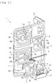
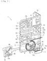
- the storage tray 1 is securable to a predetermined portion (the secured portion Ka) of the medical apparatus K and includes, as illustrated in Figs. 3 to 7 , a tray body 2 in which the plurality of flexible tubes (L1 to L4) are storable, a receiving portion 3 provided at a lower peripheral portion of the tray body 2, and storage portions 4 to 7 provided at respective predetermined positions of the tray body 2.
- Figs. 3 to 7 each illustrate a state where only the storage portion 7 is used for storing the flexible tube L1 (the other flexible tubes are attached to the medical apparatus K). In a stored state, the storage portions 4 to 6 are also used for storing the flexible tubes (L2 to L4), respectively.
- the storage tray 1 is a resin molded member including various portions integrally formed together.
- the member is folded into a component including the receiving portion 3, a securing portion 11, and so forth.
- a side peripheral portion of the tray body 2 is folded into an L shape, whereby a folded portion 2a is provided.
- a lower peripheral portion of the tray body 2 is folded and an extended portion 2b is inserted into a slit a, whereby the receiving portion 3 is provided.
- a covering portion 3a is folded, whereby the top of the receiving portion 3 is covered with the covering portion 3a.
- the tray body 2 has the securing portion 11 that is capable of securing a predetermined portion of the medical apparatus K. Therefore, the tray body 2 is detachable from and attachable to the medical apparatus. Specifically, as illustrated in Fig. 8 , the securing portion 11 is provided in the form of a cut that is made in the folded portion 2a, which is obtained by folding the side peripheral portion of the tray body 2 into an L shape.
- the storage tray 1 can be secured to the medical apparatus K (see Figs. 10 and 11 ) by hooking the securing portion 11 on the secured portion Ka of the medical apparatus.
- the storage tray 1 can be detached from the medical apparatus K by unhooking the securing portion 11 from the secured portion Ka (see Fig. 9 for the detached state).
- the storage portions 4 to 7 are each a portion capable of storing a corresponding one of the flexible tubes (L1 to L4) in a wound state.
- the flexible tube L3 (a flushing line) is stored in the storage portion 4
- the flexible tube L1 (a heparinized-physiological-saline-solution line) is stored in the storage portion 5
- the flexible tubes L4 (calibration lines) are stored in the storage portion 6
- the flexible tube L2 (a patient line) is stored in the storage portion 7.
- the storage portions 4 to 7 each include a spool part 8, a fitting part 9, and a lid part 10.
- the spool part 8 is a projected portion around which the flexible tube (one of L1 to L4) is windable to be stored.
- the fitting part 9 is provided in the upper surface of the spool part 8. An end portion of the flexible tube (one of L1 to L4) that is wound around the spool part 8 is fittable into and securable in the fitting part 9. That is, the fitting part 9 is a groove having substantially the same shape and size as the end portion of the flexible tube (one of L1 to L4) so that the fitting part 9 can receive and secure the end portion of the flexible tube (one of L1 to L4) that is wound around the spool part 8.
- the storage portions (4 to 7) each have an indication showing the position of connection of the corresponding one of the flexible tubes (L1 to L4) that is wound around the spool part 8 to the medical apparatus K (a corresponding one of character strings saying "FLUSHING LINE,” “HEPARINIZED-PHYSIOLOGICAL-SALINE-SOLUTION LINE,” “CALIBRATION LINE,” and “PATIENT LINE”) and the order of connection (a corresponding one of numbers (1) to (4)).
- the position of connection and the order of connection are provided on the lid part 10.
- the position of connection and the order of connection may be provided on another position (any portion corresponding to each of the storage portions 4 to 7).
- only one of the position of connection and the order of connection may be provided.
- the lid part 10 is a flat part provided at an end of an extended portion 10c extended from a side periphery of the tray body 2.
- the lid part 10 covers the flexible tube (one of L1 to L4) wound around the spool part 8 and thus prevents the flexible tube (one of L1 to L4) from coming off the spool part. That is, the lid parts 10 are provided at respective positions in correspondence with the spool parts 8, and projections 10a of each of the lid part 10 are fitted into and thus secured in respective recesses 8a provided in a corresponding one of the spool parts 8.
- the lid parts 10 cover the flexible tubes (L1 to L4) wound around the spool parts 8 and retain the flexible tubes (L1 to L4) in the wound state.
- the receiving portion 3 included in the tray body 2 is a container-like portion capable of receiving a priming solution and storing a predetermined volume of priming solution.
- the priming solution is used for flushing the flexible tubes (L1 to L4) attached to the medical apparatus K.
- the predetermined volume may be determined appropriately on the basis of, for example, the volume of priming solution that is discharged from a discharge portion when the flexible tubes (L1 to L4) are flushed.
- the priming solution in the flexible tube L1 is dischargeable from the discharge portion (the distal end at which the invasive catheter H is attached). In a state where the flexible tube L1 is stored in the tray body 2, the discharge portion is set in a state where the priming solution is dischargeable into the receiving portion 3.
- a cap 12 for covering and protecting the discharge portion of the flexible tube L1 is attached to the discharge portion.
- the cap 12 With the flexible tube L1 stored in the tray body 2 (that is, in a state where the flexible tube L1 is stored in the storage portion 7), the cap 12 is inserted into the receiving portion 3.
- the receiving portion 3 includes the covering portion 3a that covers a storage space in which the priming solution is stored, and the covering portion 3a has an insertion hole 3aa into which the cap 12 is inserted.
- the priming solution supplied during priming in the embodiment, the physiological saline solution supplied from the storage bag B2 flows through the flexible tubes (L1 to L4) and through the cap 12 and is received by the receiving portion 3.
- the embodiment employs the tray body 2 that is securable to a predetermined portion of the medical apparatus K and in which the flexible tubes (L1 to L4) are storable, and the receiving portion 3 that is included in the tray body 2 and is capable of receiving the priming solution, which is used for flushing the flexible tubes (L1 to L4) attached to the medical apparatus K, and storing a predetermined volume of priming solution. Therefore, not only the flexible tubes (L1 to L4) can be stored, but the efficiency of the work to be performed after priming can also be improved.
- the priming solution is storable in the receiving portion 3 during priming. Therefore, after the priming is finished, the tray body 2 with all of the flexible tubes (L1 to L4) removed from the storage portions (4 to 7) thereof can be disposed of simultaneously with the priming solution. Thus, the working efficiency can be improved.
- the discharge portion of the flexible tube L1 from which the priming solution is dischargeable is set in a state where the priming solution is dischargeable into the receiving portion 3. Therefore, during priming, the priming solution can be assuredly and smoothly discharged into and stored in the receiving portion.
- the cap 12 for covering and protecting the discharge portion of the flexible tube L1 is provided, and the cap 12 is inserted into the receiving portion 3 with the flexible tubes (L1 to L4) stored in the tray body 2. Therefore, the discharge portion can be protected by the cap 12, and the priming solution can be assuredly and smoothly discharged into and stored in the receiving portion 3 during priming.
- the receiving portion 3 includes the covering portion 3a that covers the storage space in which the priming solution is stored, and the covering portion 3a has the insertion hole 3aa into which the cap 12 is inserted. Therefore, the priming solution discharged into the receiving portion 3 can be prevented from scattering around the receiving portion 3. Moreover, the leakage of the priming solution from the receiving portion 3 that may occur at the disposal of the tray body 2 can be suppressed.
- the tray body 2 includes the securing portion 11 that is capable of securing a predetermined portion (the secured portion Ka) of the medical apparatus K, whereby the tray body 2 is detachable from and attachable to the medical apparatus K. Therefore, after the flexible tubes (L1 to L4) are attached to the medical apparatus K, the storage tray 1 can be easily detached and disposed of. Furthermore, the tray body 2 includes the storage portions (4 to 7) in which the respective flexible tubes (L1 to L4) are storable in the wound state. Therefore, the flexible tubes can be attached to the medical apparatus by unwinding the flexible tubes that are in the wound state from the storage portions. Consequently, no binding tape or the like need to be provided separately.
- the storage portions (4 to 7) each include the spool part 8 around which a corresponding one of the flexible tubes (L1 to L4) is windable to be stored, the fitting part 9 in which the end portion of the flexible tube (one of L1 to L4) that is wound around the spool part 8 is fittable and thus securable, and the lid part 10 that covers the flexible tube (one of L1 to L4) wound around the spool part 8 and thus prevents the flexible tube (one of L1 to L4) from coming off the spool part 8. Therefore, the flexible tubes (L1 to L4) can be stored assuredly and in a compact size.
- the storage portions 4 to 7 each have an indication showing the position of connection or the order of connection of a corresponding one of the flexible tubes (L1 to L4) wound around the respective spool parts 8 to the medical apparatus K. Therefore, the work of attaching the flexible tubes (L1 to L4) to the medical apparatus K can be performed more smoothly and more assuredly.
- the storage tray may store any number of flexible tubes other than four, or the storage tray may store only one flexible tube.
- the tray body 2 in which the flexible tubes (L1 to L4) are stored is attached to the medical apparatus K. Then, after the priming is finished, the tray body 2 is detached from the medical apparatus K and is disposed of. Alternatively, the tray body 2 may be kept attached to the medical apparatus K.
- the medical apparatus K to which the flexible tubes (L1 to L4) are to be attached may be in any mode.
- the storage tray according to the present invention may have any other external shape or any other additional functions, as long as the storage tray includes a tray body that is securable to a predetermined portion of a medical apparatus and in which flexible tubes are storable, and a receiving portion that is included in the tray body and is capable of receiving and storing a predetermined volume of priming solution that is used for flushing the flexible tubes attached to the medical apparatus.
Landscapes
- Health & Medical Sciences (AREA)
- Life Sciences & Earth Sciences (AREA)
- Engineering & Computer Science (AREA)
- Physics & Mathematics (AREA)
- Veterinary Medicine (AREA)
- Biomedical Technology (AREA)
- Heart & Thoracic Surgery (AREA)
- Animal Behavior & Ethology (AREA)
- General Health & Medical Sciences (AREA)
- Public Health (AREA)
- Surgery (AREA)
- Pathology (AREA)
- Molecular Biology (AREA)
- Medical Informatics (AREA)
- Biophysics (AREA)
- Hematology (AREA)
- Diabetes (AREA)
- Manufacturing & Machinery (AREA)
- Optics & Photonics (AREA)
- Mechanical Engineering (AREA)
- Quality & Reliability (AREA)
- Anesthesiology (AREA)
- Vascular Medicine (AREA)
- Chemical & Material Sciences (AREA)
- Chemical Kinetics & Catalysis (AREA)
- General Chemical & Material Sciences (AREA)
- Emergency Medicine (AREA)
- External Artificial Organs (AREA)
- Infusion, Injection, And Reservoir Apparatuses (AREA)
- Basic Packing Technique (AREA)
Abstract
Description
- The present invention relates to a storage tray to be attached to a medical apparatus and in which a plurality of flexible tubes that each allow fluid to flow therethrough are stored.
- A blood glucose controlling device according to a known proposal is configured as follows. While blood is collected from the body of a patient, the collected blood is diluted with a predetermined diluent and the blood sugar level of the blood is measured in real time by a blood-sugar-level-measurement device such as a glucose sensor. If the measured blood sugar level is too high, insulin is injected into the patient, whereby the blood sugar level is lowered. If the measured blood sugar level is too low, grape sugar (glucose) is injected into the patient, whereby the blood sugar level is raised.
- Such a blood glucose controlling device is provided with, as disclosed by
PTL 1 for example, a dilution device (a sampling device) for diluting the blood to be supplied to the blood-sugar-level-measurement device. A known dilution device is provided with a plurality of flexible tubes that allow different kinds of liquid, such as blood and diluent, to flow therethrough, respectively. Typically, such flexible tubes are distributed in units of several pieces that are packed in a resin storage bag. Therefore, to attach the flexible tubes packed in the bag to respective positions of the dilution device, the bag needs to be ripped off. - PTL 1: Japanese Unexamined Patent Application Publication No.
2013-245664 - According to the above known technique, however, when the plurality of flexible tubes taken out of the storage bag and attached to a medical apparatus are charged by causing a priming solution (such as a physiological saline solution) to flow through those flexible tubes, the priming solution needs to be received by a separately provided container. Therefore, after such priming is finished, the storage bag in which the flexible tubes have been packed and the separately provided container in which the priming solution has been received need to be disposed of separately, which adversely affects working efficiency.
- The present invention has been conceived in view of the above circumstances and provides a storage tray in which flexible tubes are to be stored and with which the efficiency of work to be performed after priming can be improved.
- According to the invention of
Claim 1, there is provided a storage tray that stores a flexible tube to be attached to a medical apparatus, the flexible tube allowing fluid to flow therethrough. The storage tray includes a tray body that is securable to a predetermined portion of the medical apparatus and in which the flexible tube is storable, and a receiving portion that is included in the tray body and is capable of receiving a priming solution and storing a predetermined volume of priming solution, the priming solution being used for flushing the flexible tube attached to the medical apparatus. - According to the invention of
Claim 2, in the storage tray according toClaim 1, the flexible tube has a discharge portion from which the priming solution is dischargeable. Furthermore, in a state where the flexible tube is stored in the tray body, the discharge portion is set in a state where the priming solution is dischargeable into the receiving portion. - According to the invention of
Claim 3, in the storage tray according toClaim 2, the discharge portion is provided with a cap that covers and protects the discharge portion. Furthermore, the cap is inserted into the receiving portion with the flexible tube stored in the tray body. - According to the invention of
Claim 4, in the storage tray according toClaim 3, the receiving portion includes a covering portion that covers a storage space in which the priming solution is stored. Furthermore, the covering portion has an insertion hole into which the cap is inserted. - According to the invention of
Claim 5, in the storage tray according to any ofClaims 1 to 4, the tray body includes a securing portion that is capable of securing a predetermined portion of the medical apparatus such that the tray body is detachable from and attachable to the medical apparatus. - According to the invention of
Claim 6, in the storage tray according to any ofClaims 1 to 5, the tray body includes a storage portion in which each flexible tube is storable in a wound state. - According to the invention of
Claim 7, in the storage tray according toClaim 6, the storage portion includes a spool part around which the flexible tube is windable to be stored, a fitting part in which an end portion of the flexible tube wound around the spool part is fittable and securable, and a lid part that covers the flexible tube wound around the spool part and prevents the flexible tube from coming off the spool part. - According to the invention of
Claim 8, in the storage tray according toClaim 7, the storage portion has an indication showing a position of connection and/or an order of connection of the flexible tube wound around the spool part to the medical apparatus. - According to the invention of
Claim 1, the storage tray includes the tray body that is securable to the predetermined portion of the medical apparatus and in which the flexible tube is storable, and the receiving portion that is included in the tray body and is capable of receiving the priming solution and storing the predetermined volume of priming solution, the priming solution being used for flushing the flexible tube attached to the medical apparatus. Hence, not only the flexible tube can be stored, but the efficiency of the work to be performed after priming can also be improved. - According to the invention of
Claim 2, the flexible tube has the discharge portion from which the priming solution is dischargeable. Furthermore, in the state where the flexible tube is stored in the tray body, the discharge portion is set in the state where the priming solution is dischargeable into the receiving portion. Hence, during priming, the priming solution can be assuredly and smoothly discharged into and stored in the receiving portion. - According to the invention of
Claim 3, the discharge portion is provided with the cap that covers and protects the discharge portion. Furthermore, the cap is inserted into the receiving portion with the flexible tube stored in the tray body. Hence, the discharge portion can be protected by the cap, and the priming solution can be assuredly and smoothly discharged into and stored in the receiving portion during priming. - According to the invention of
Claim 4, the receiving portion includes the covering portion that covers the storage space in which the priming solution is stored. Furthermore, the covering portion has the insertion hole into which the cap is inserted. Hence, the priming solution discharged into the receiving portion can be prevented from scattering around the receiving portion. Moreover, the leakage of the priming solution from the receiving portion that may occur at the disposal of the tray body can be suppressed. - According to the invention of
Claim 5, the tray body includes the securing portion that is capable of securing the predetermined portion of the medical apparatus such that the tray body is detachable from and attachable to the medical apparatus. Hence, after the flexible tube is attached to the medical apparatus, the storage tray can be easily detached and disposed of. - According to the invention of
Claim 6, the tray body includes the storage portion in which each flexible tube is storable in the wound state. Hence, the flexible tubes can be attached to the medical apparatus by unwinding the flexible tubes that are in the wound state from the storage portions. Consequently, no binding tape or the like need to be provided separately. - According to the invention of
Claim 7, the storage portion includes the spool part around which the flexible tube is windable to be stored, the fitting part in which the end portion of the flexible tube wound around the spool part is fittable and securable, and the lid part that covers the flexible tube wound around the spool part and prevents the flexible tube from coming off the spool part. Hence, the flexible tube can be stored assuredly and in a compact size. - According to the invention of
Claim 8, the storage portion has the indication showing the position of connection and/or the order of connection of the flexible tube wound around the spool part to the medical apparatus. Hence, the work of attaching the flexible tube to the medical apparatus can be performed more smoothly and more assuredly. -
- [
Fig. 1] Fig. 1 is a schematic diagram illustrating a dilution device and a blood-sugar-level-measurement device to which a storage tray according to an embodiment of the present invention is applied. - [
Fig. 2] Fig. 2 is a schematic view illustrating an invasive catheter included in the dilution device. - [
Fig. 3] Fig. 3 includes a front view and a bottom view of the storage tray. - [
Fig. 4] Fig. 4 is a perspective view of the storage tray (with all lid portions thereof closed). - [
Fig. 5] Fig. 5 is another perspective view of the storage tray (with all the lid portions thereof closed). - [
Fig. 6] Fig. 6 is yet another perspective view of the storage tray (with one of the lid portions thereof open). - [
Fig. 7] Fig. 7 is yet another perspective view of the storage tray (with one of the lid portions thereof open). - [
Fig. 8] Fig. 8 includes a front view and a bottom view of the storage tray that is yet to be folded. - [
Fig. 9] Fig. 9 is a front external view of the dilution device and the blood-sugar-level-measurement device (with the storage tray yet to be secured thereto) to which the storage tray is applied. - [
Fig. 10] Fig. 10 is another front external view of the dilution device and the blood-sugar-level-measurement device (with the storage tray secured thereto) to which the storage tray is applied. - [
Fig. 11] Fig. 11 is a rear external perspective view of the dilution device and the blood-sugar-level-measurement device (with the storage tray secured thereto) to which the storage tray is applied. - An embodiment of the present invention will now be described specifically with reference to the drawings.
- As illustrated in
Figs. 1 and 2 , a dilution device A according to the embodiment is a medical device connected to a blood-sugar-level-measurement device S capable of measuring the level of blood sugar contained in blood. The dilution device A includes a multipump P including peristaltic pumps. The dilution device A is provided with a plurality of flexible tubes (L1 to L4). The dilution device A is intended to dilute the blood of a patient so that a glucose sensor T included in the blood-sugar-level-measurement device S can measure the blood sugar level. The dilution device A is included in a medical apparatus K that appears as illustrated inFigs. 9 to 11 . - The flexible tube L1 forms a liquid flow route with one end thereof connected to a storage bag B1 that stores a heparinized physiological saline solution, which is obtained by adding heparin (an anticoagulant) to a physiological saline solution, and with the other end thereof connected to an invasive catheter H. The flexible tube L2 forms a liquid flow route with one end thereof connected to the invasive catheter H and with the other end thereof connected to a mixing unit M, such as a chamber, included in the blood-sugar-level-measurement device S. The flexible tube L3 forms a liquid flow route with one end thereof connected to a storage bag B2 that stores a physiological saline solution and with the other end thereof connected to a predetermined position of the flexible tube L2. The flexible tubes L4 each form a liquid flow route with one end thereof connected to a storage bag B3 that stores a reference glucose solution and with the other end thereof connected to a predetermined position of a corresponding one of the flexible tube L1 and the flexible tube L2.
- The invasive catheter H is connected to the distal end of the flexible tube L1 and to the distal end of the flexible tube L2 and is indwelling into the patient. The invasive catheter H allows the diluent in the storage bag B1 to be introduced thereinto while collecting the blood of the patient thereinto, and also allows a mixture of the blood and the diluent to be supplied into the mixing unit M of the blood-sugar-level-measurement device S. The mixing unit M is connected to the glucose sensor T of the blood-sugar-level-measurement device S. Hence, the diluted solution having been mixed substantially evenly in the mixing unit M is supplied to the glucose sensor T through flexible tubes L7 and L8.
- With the supply of the physiological saline solution from the storage bag B2, the flexible tubes L1 to L10 and associated components provided to the dilution device A and to the blood-sugar-level-measurement device S can be charged (can undergo priming). Furthermore, with the supply of the reference glucose solution from the storage bag B3, the glucose sensor T measures the blood sugar level. Therefore, the glucose sensor T can be calibrated.
- The multipump P allows the diluent and the blood to simultaneously flow at a predetermined ratio through the flexible tubes L1 and L2 attached thereto. The multipump P includes a plurality of rotors rotatable by respective motors, and rollers attached to the respective rotors and causing liquid to flow through the flexible tubes L1 and L2 by squeezing the flexible tubes L1 and L2. Note that flexible tubes L5, L6, and L9 included in the blood-sugar-level-measurement device S are also attached to the multipump P, and the flexible tubes L1, L2, L5, L6, and L9 are squeezed simultaneously, whereby the liquid is allowed to flow therethrough.
- The blood-sugar-level-measurement device S includes the flexible tube L5 with one end thereof connected to a storage bag B4 storing the diluent and with the other end thereof connected to the mixing unit M, the flexible tube L6 with one end thereof being open to the atmosphere and with the other end thereof connected to the mixing unit M, the flexible tube L7 with one end thereof connected to the mixing unit M and with the other end thereof connected to a chamber N, the flexible tube L8 with one end thereof connected to the chamber N and with the other end thereof connected to the glucose sensor T, the flexible tube L9 with one end thereof connected to the glucose sensor T and with the other end thereof connected to a storage bag B5 storing waste liquid, and a flexible tube L10 with one end thereof connected to the chamber N and with the other end thereof connected to the storage bag B5.
- The glucose sensor T continuously introduces the diluted blood of the patient that is supplied from the dilution device A onto an enzyme membrane and decomposes glucose contained in the diluted blood. When the glucose is decomposed, an electric current is generated. The glucose sensor T is capable of measuring the blood sugar level from the electric current. The glucose sensor T is connected to the drainage bag B5 with the flexible tube L9. The blood of the patient supplied to the mixing unit M through the flexible tube L2 (the blood diluted with the heparinized physiological saline solution) is further diluted with the diluent supplied through the flexible tube L5. Then, the blood sugar level of the diluted blood is measured by the glucose sensor T. The diluted blood is discharged into the drainage bag B5 through the flexible tube L9. Note that the mixing unit M is supplied with air through the flexible tube L6 so that blood and the diluent can be mixed in a good manner.
- The plurality of flexible tubes L1 to L4 to be attached to the medical apparatus (in the embodiment, the medical apparatus K including the dilution device A and the blood-sugar-level-measurement device S) are stored in a
storage tray 1 as illustrated inFigs. 3 to 7 . As illustrated inFigs. 9 to 11 , the medical apparatus K according to the embodiment includes a monitor J capable of displaying conditions of setting and so forth, hooks F on which the storage bags (B1 to B5) are hookable, and so forth. The medical apparatus K has a secured portion Ka at a predetermined position thereof. - The
storage tray 1 according to the embodiment is securable to a predetermined portion (the secured portion Ka) of the medical apparatus K and includes, as illustrated inFigs. 3 to 7 , atray body 2 in which the plurality of flexible tubes (L1 to L4) are storable, a receivingportion 3 provided at a lower peripheral portion of thetray body 2, andstorage portions 4 to 7 provided at respective predetermined positions of thetray body 2.Figs. 3 to 7 each illustrate a state where only thestorage portion 7 is used for storing the flexible tube L1 (the other flexible tubes are attached to the medical apparatus K). In a stored state, thestorage portions 4 to 6 are also used for storing the flexible tubes (L2 to L4), respectively. - As illustrated in
Fig. 8 , thestorage tray 1 according to the embodiment is a resin molded member including various portions integrally formed together. The member is folded into a component including the receivingportion 3, a securingportion 11, and so forth. Specifically, a side peripheral portion of thetray body 2 is folded into an L shape, whereby a foldedportion 2a is provided. Furthermore, a lower peripheral portion of thetray body 2 is folded and anextended portion 2b is inserted into a slit a, whereby the receivingportion 3 is provided. Furthermore, a coveringportion 3a is folded, whereby the top of the receivingportion 3 is covered with the coveringportion 3a. - The
tray body 2 has the securingportion 11 that is capable of securing a predetermined portion of the medical apparatus K. Therefore, thetray body 2 is detachable from and attachable to the medical apparatus. Specifically, as illustrated inFig. 8 , the securingportion 11 is provided in the form of a cut that is made in the foldedportion 2a, which is obtained by folding the side peripheral portion of thetray body 2 into an L shape. Thestorage tray 1 can be secured to the medical apparatus K (seeFigs. 10 and11 ) by hooking the securingportion 11 on the secured portion Ka of the medical apparatus. Thestorage tray 1 can be detached from the medical apparatus K by unhooking the securingportion 11 from the secured portion Ka (seeFig. 9 for the detached state). - As illustrated in
Figs. 3 to 8 , thestorage portions 4 to 7 are each a portion capable of storing a corresponding one of the flexible tubes (L1 to L4) in a wound state. The flexible tube L3 (a flushing line) is stored in thestorage portion 4, the flexible tube L1 (a heparinized-physiological-saline-solution line) is stored in thestorage portion 5, the flexible tubes L4 (calibration lines) are stored in thestorage portion 6, and the flexible tube L2 (a patient line) is stored in thestorage portion 7. Thestorage portions 4 to 7 according to the embodiment each include aspool part 8, afitting part 9, and alid part 10. - More specifically, the
spool part 8 is a projected portion around which the flexible tube (one of L1 to L4) is windable to be stored. Thefitting part 9 is provided in the upper surface of thespool part 8. An end portion of the flexible tube (one of L1 to L4) that is wound around thespool part 8 is fittable into and securable in thefitting part 9. That is, thefitting part 9 is a groove having substantially the same shape and size as the end portion of the flexible tube (one of L1 to L4) so that thefitting part 9 can receive and secure the end portion of the flexible tube (one of L1 to L4) that is wound around thespool part 8. - Furthermore, the storage portions (4 to 7) according to the embodiment each have an indication showing the position of connection of the corresponding one of the flexible tubes (L1 to L4) that is wound around the
spool part 8 to the medical apparatus K (a corresponding one of character strings saying "FLUSHING LINE," "HEPARINIZED-PHYSIOLOGICAL-SALINE-SOLUTION LINE," "CALIBRATION LINE," and "PATIENT LINE") and the order of connection (a corresponding one of numbers (1) to (4)). In the embodiment, the position of connection and the order of connection are provided on thelid part 10. Alternatively, the position of connection and the order of connection may be provided on another position (any portion corresponding to each of thestorage portions 4 to 7). Moreover, only one of the position of connection and the order of connection may be provided. - As illustrated in
Fig. 8 , thelid part 10 is a flat part provided at an end of anextended portion 10c extended from a side periphery of thetray body 2. As illustrated inFigs. 3 to 7 , thelid part 10 covers the flexible tube (one of L1 to L4) wound around thespool part 8 and thus prevents the flexible tube (one of L1 to L4) from coming off the spool part. That is, thelid parts 10 are provided at respective positions in correspondence with thespool parts 8, andprojections 10a of each of thelid part 10 are fitted into and thus secured inrespective recesses 8a provided in a corresponding one of thespool parts 8. Thus, thelid parts 10 cover the flexible tubes (L1 to L4) wound around thespool parts 8 and retain the flexible tubes (L1 to L4) in the wound state. - As illustrated in
Figs. 3 to 8 , the receivingportion 3 included in thetray body 2 is a container-like portion capable of receiving a priming solution and storing a predetermined volume of priming solution. The priming solution is used for flushing the flexible tubes (L1 to L4) attached to the medical apparatus K. The predetermined volume may be determined appropriately on the basis of, for example, the volume of priming solution that is discharged from a discharge portion when the flexible tubes (L1 to L4) are flushed. In the embodiment, the priming solution in the flexible tube L1 is dischargeable from the discharge portion (the distal end at which the invasive catheter H is attached). In a state where the flexible tube L1 is stored in thetray body 2, the discharge portion is set in a state where the priming solution is dischargeable into the receivingportion 3. - Specifically, a
cap 12 for covering and protecting the discharge portion of the flexible tube L1 is attached to the discharge portion. With the flexible tube L1 stored in the tray body 2 (that is, in a state where the flexible tube L1 is stored in the storage portion 7), thecap 12 is inserted into the receivingportion 3. Furthermore, the receivingportion 3 according to the embodiment includes the coveringportion 3a that covers a storage space in which the priming solution is stored, and the coveringportion 3a has an insertion hole 3aa into which thecap 12 is inserted. Hence, the priming solution supplied during priming (in the embodiment, the physiological saline solution supplied from the storage bag B2) flows through the flexible tubes (L1 to L4) and through thecap 12 and is received by the receivingportion 3. - The embodiment employs the
tray body 2 that is securable to a predetermined portion of the medical apparatus K and in which the flexible tubes (L1 to L4) are storable, and the receivingportion 3 that is included in thetray body 2 and is capable of receiving the priming solution, which is used for flushing the flexible tubes (L1 to L4) attached to the medical apparatus K, and storing a predetermined volume of priming solution. Therefore, not only the flexible tubes (L1 to L4) can be stored, but the efficiency of the work to be performed after priming can also be improved. This means as follows. The priming solution is storable in the receivingportion 3 during priming. Therefore, after the priming is finished, thetray body 2 with all of the flexible tubes (L1 to L4) removed from the storage portions (4 to 7) thereof can be disposed of simultaneously with the priming solution. Thus, the working efficiency can be improved. - According to the embodiment, in the state where the flexible tubes (L1 to L4) are stored in the
tray body 2, the discharge portion of the flexible tube L1 from which the priming solution is dischargeable is set in a state where the priming solution is dischargeable into the receivingportion 3. Therefore, during priming, the priming solution can be assuredly and smoothly discharged into and stored in the receiving portion. In particular, according to the embodiment, thecap 12 for covering and protecting the discharge portion of the flexible tube L1 is provided, and thecap 12 is inserted into the receivingportion 3 with the flexible tubes (L1 to L4) stored in thetray body 2. Therefore, the discharge portion can be protected by thecap 12, and the priming solution can be assuredly and smoothly discharged into and stored in the receivingportion 3 during priming. - Furthermore, the receiving
portion 3 according to the embodiment includes the coveringportion 3a that covers the storage space in which the priming solution is stored, and the coveringportion 3a has the insertion hole 3aa into which thecap 12 is inserted. Therefore, the priming solution discharged into the receivingportion 3 can be prevented from scattering around the receivingportion 3. Moreover, the leakage of the priming solution from the receivingportion 3 that may occur at the disposal of thetray body 2 can be suppressed. - Furthermore, the
tray body 2 according to the embodiment includes the securingportion 11 that is capable of securing a predetermined portion (the secured portion Ka) of the medical apparatus K, whereby thetray body 2 is detachable from and attachable to the medical apparatus K. Therefore, after the flexible tubes (L1 to L4) are attached to the medical apparatus K, thestorage tray 1 can be easily detached and disposed of. Furthermore, thetray body 2 includes the storage portions (4 to 7) in which the respective flexible tubes (L1 to L4) are storable in the wound state. Therefore, the flexible tubes can be attached to the medical apparatus by unwinding the flexible tubes that are in the wound state from the storage portions. Consequently, no binding tape or the like need to be provided separately. - Furthermore, the storage portions (4 to 7) each include the
spool part 8 around which a corresponding one of the flexible tubes (L1 to L4) is windable to be stored, thefitting part 9 in which the end portion of the flexible tube (one of L1 to L4) that is wound around thespool part 8 is fittable and thus securable, and thelid part 10 that covers the flexible tube (one of L1 to L4) wound around thespool part 8 and thus prevents the flexible tube (one of L1 to L4) from coming off thespool part 8. Therefore, the flexible tubes (L1 to L4) can be stored assuredly and in a compact size. Moreover, thestorage portions 4 to 7 each have an indication showing the position of connection or the order of connection of a corresponding one of the flexible tubes (L1 to L4) wound around therespective spool parts 8 to the medical apparatus K. Therefore, the work of attaching the flexible tubes (L1 to L4) to the medical apparatus K can be performed more smoothly and more assuredly. - While an embodiment of the present invention has been described above, the present invention is not limited thereto. For example, the storage tray may store any number of flexible tubes other than four, or the storage tray may store only one flexible tube. Furthermore, according to the embodiment, the
tray body 2 in which the flexible tubes (L1 to L4) are stored is attached to the medical apparatus K. Then, after the priming is finished, thetray body 2 is detached from the medical apparatus K and is disposed of. Alternatively, thetray body 2 may be kept attached to the medical apparatus K. In addition, the medical apparatus K to which the flexible tubes (L1 to L4) are to be attached may be in any mode. - The storage tray according to the present invention may have any other external shape or any other additional functions, as long as the storage tray includes a tray body that is securable to a predetermined portion of a medical apparatus and in which flexible tubes are storable, and a receiving portion that is included in the tray body and is capable of receiving and storing a predetermined volume of priming solution that is used for flushing the flexible tubes attached to the medical apparatus.
-
- 1 storage tray
- 2 tray body
- 3 receiving portion
- 4 to 7 storage portion
- 8 spool part
- 9 fitting part
- 10 lid part
- 11 securing portion
- K medical apparatus
Claims (8)
- A storage tray that stores a flexible tube to be attached to a medical apparatus, the flexible tube allowing fluid to flow therethrough, the storage tray comprising:a tray body that is securable to a predetermined portion of the medical apparatus and in which the flexible tube is storable; anda receiving portion that is included in the tray body and is capable of receiving a priming solution and storing a predetermined volume of priming solution, the priming solution being used for flushing the flexible tube attached to the medical apparatus.
- The storage tray according to Claim 1, wherein the flexible tube has a discharge portion from which the priming solution is dischargeable, and wherein in a state where the flexible tube is stored in the tray body, the discharge portion is set in a state where the priming solution is dischargeable into the receiving portion.
- The storage tray according to Claim 2, wherein the discharge portion is provided with a cap that covers and protects the discharge portion, and wherein the cap is inserted into the receiving portion with the flexible tube stored in the tray body.
- The storage tray according to Claim 3, wherein the receiving portion includes a covering portion that covers a storage space in which the priming solution is stored, and wherein the covering portion has an insertion hole into which the cap is inserted.
- The storage tray according to any of Claims 1 to 4, wherein the tray body includes a securing portion that is capable of securing a predetermined portion of the medical apparatus such that the tray body is detachable from and attachable to the medical apparatus.
- The storage tray according to any of Claims 1 to 5, wherein the tray body includes a storage portion in which each flexible tube is storable in a wound state.
- The storage tray according to Claim 6, wherein the storage portion includes a spool part around which the flexible tube is windable to be stored, a fitting part in which an end portion of the flexible tube wound around the spool part is fittable and securable, and a lid part that covers the flexible tube wound around the spool part and prevents the flexible tube from coming off the spool part.
- The storage tray according to Claim 7, wherein the storage portion has an indication showing a position of connection and/or an order of connection of the flexible tube wound around the spool part to the medical apparatus.
Applications Claiming Priority (2)
| Application Number | Priority Date | Filing Date | Title |
|---|---|---|---|
| JP2015198489A JP6246772B2 (en) | 2015-10-06 | 2015-10-06 | Storage tray |
| PCT/JP2016/079613 WO2017061465A1 (en) | 2015-10-06 | 2016-10-05 | Storage tray |
Publications (3)
| Publication Number | Publication Date |
|---|---|
| EP3351276A1 true EP3351276A1 (en) | 2018-07-25 |
| EP3351276A4 EP3351276A4 (en) | 2019-06-19 |
| EP3351276B1 EP3351276B1 (en) | 2021-05-05 |
Family
ID=58487707
Family Applications (1)
| Application Number | Title | Priority Date | Filing Date |
|---|---|---|---|
| EP16853619.1A Active EP3351276B1 (en) | 2015-10-06 | 2016-10-05 | Storage tray |
Country Status (5)
| Country | Link |
|---|---|
| US (1) | US10820846B2 (en) |
| EP (1) | EP3351276B1 (en) |
| JP (1) | JP6246772B2 (en) |
| CN (1) | CN108136104A (en) |
| WO (1) | WO2017061465A1 (en) |
Families Citing this family (1)
| Publication number | Priority date | Publication date | Assignee | Title |
|---|---|---|---|---|
| JP2023062542A (en) * | 2021-10-21 | 2023-05-08 | ニプロ株式会社 | medical device package |
Family Cites Families (23)
| Publication number | Priority date | Publication date | Assignee | Title |
|---|---|---|---|---|
| US4120394A (en) * | 1976-08-23 | 1978-10-17 | Soltes Isaac B | Case for carrying pendant and chain |
| US4479761A (en) * | 1982-12-28 | 1984-10-30 | Baxter Travenol Laboratories, Inc. | Actuator apparatus for a prepackaged fluid processing module having pump and valve elements operable in response to externally applied pressures |
| US4479762A (en) * | 1982-12-28 | 1984-10-30 | Baxter Travenol Laboratories, Inc. | Prepackaged fluid processing module having pump and valve elements operable in response to applied pressures |
| US5324180A (en) * | 1992-09-04 | 1994-06-28 | Allergan, Inc. | Surgical instrument with drawer loading cassette system |
| DE69421063T2 (en) * | 1993-11-05 | 2000-03-02 | Elf Atochem S.A., Puteaux | PACKAGING WITH RESTRICTED OXYGEN PERMEABILITY |
| JPH08506984A (en) * | 1993-12-22 | 1996-07-30 | バクスター、インターナショナル、インコーポレイテッド | Self-priming drip chamber with improved visibility |
| US5514069A (en) * | 1993-12-22 | 1996-05-07 | Baxter International Inc. | Stress-bearing umbilicus for a compact centrifuge |
| US5650071A (en) | 1995-06-07 | 1997-07-22 | Cobe Laboratories, Inc. | Technique for priming and recirculating fluid through a dialysis machine to prepare the machine for use |
| US5964724A (en) * | 1996-01-31 | 1999-10-12 | Medtronic Electromedics, Inc. | Apparatus and method for blood separation |
| AU725188B2 (en) * | 1996-06-27 | 2000-10-05 | Huntsman Ici Chemicals Llc | Microcellular elastomeric polyurethane foams |
| US6036458A (en) * | 1997-10-03 | 2000-03-14 | Allergan Sales, Inc. | Automated phaco pack bar code reader identification |
| JP2000103079A (en) * | 1998-09-30 | 2000-04-11 | Brother Ind Ltd | ink cartridge |
| JP3954269B2 (en) * | 2000-03-13 | 2007-08-08 | テルモ株式会社 | Medical instrument storage container |
| MX351817B (en) | 2003-10-28 | 2017-10-30 | Baxter Healthcare Sa | Improved priming, integrity and head height methods and apparatuses for medical fluid systems. |
| DE602005009288D1 (en) * | 2004-07-14 | 2008-10-09 | Terumo Corp | Packaging for medical tubes |
| US8512553B2 (en) * | 2007-07-05 | 2013-08-20 | Baxter International Inc. | Extracorporeal dialysis ready peritoneal dialysis machine |
| JP4420469B2 (en) * | 2008-06-26 | 2010-02-24 | 盛岡セイコー工業株式会社 | Storage tray and storage body |
| JP5711214B2 (en) | 2009-04-23 | 2015-04-30 | フレゼニウス メディカル ケア ドイッチェランド ゲゼルシャフト ミット ベシュレンクテル ハフツング | External function means, blood processing apparatus and method for receiving external function means according to the present invention |
| EP2386327A1 (en) * | 2010-05-12 | 2011-11-16 | F. Hoffmann-La Roche AG | Device for adjusting the length of infusion tubing |
| US20130177836A1 (en) | 2011-12-13 | 2013-07-11 | Georgia Tech Research Corporation | Polyaniline-supported atomic gold electrodes and methods of making and using same |
| CA3083081A1 (en) * | 2011-12-16 | 2013-06-20 | Stryker Corporation | System for retrieving tissue samples from a fluid stream generated during a medical/surgical procedure |
| JP5872965B2 (en) * | 2012-05-29 | 2016-03-01 | 日機装株式会社 | Quantitative sampling device, biological component measuring device, and artificial pancreas device |
| CN105916542B (en) * | 2014-02-18 | 2020-01-14 | 拜耳医药保健有限公司 | Multi-dose disposable system |
-
2015
- 2015-10-06 JP JP2015198489A patent/JP6246772B2/en active Active
-
2016
- 2016-10-05 CN CN201680058404.3A patent/CN108136104A/en active Pending
- 2016-10-05 WO PCT/JP2016/079613 patent/WO2017061465A1/en not_active Ceased
- 2016-10-05 EP EP16853619.1A patent/EP3351276B1/en active Active
-
2018
- 2018-04-04 US US15/944,946 patent/US10820846B2/en active Active
Also Published As
| Publication number | Publication date |
|---|---|
| WO2017061465A1 (en) | 2017-04-13 |
| EP3351276B1 (en) | 2021-05-05 |
| US10820846B2 (en) | 2020-11-03 |
| US20180220946A1 (en) | 2018-08-09 |
| CN108136104A (en) | 2018-06-08 |
| EP3351276A4 (en) | 2019-06-19 |
| JP6246772B2 (en) | 2017-12-13 |
| JP2017070414A (en) | 2017-04-13 |
Similar Documents
| Publication | Publication Date | Title |
|---|---|---|
| JP6356872B2 (en) | Storage tray | |
| CN104107054B (en) | For collecting the medical apparatus of biological sample | |
| CN110662478B (en) | Endoscope system | |
| CA3083014C (en) | Urinary catheter assemblies and packaging for such assemblies | |
| US3783996A (en) | Syringe package | |
| DE60036711T2 (en) | BLOOD EXAMINATION SET WITH INTEGRATED BLOOD SAMPLING | |
| US20050027233A1 (en) | Devices for collecting blood and administering medical fluids | |
| EP2252212A1 (en) | Safety blood collection assembly with indicator | |
| US20220354393A1 (en) | Pedestal for sensor assembly packaging and sensor introducer removal | |
| WO2010096054A1 (en) | Supply organizers and methods for health management | |
| US20100273248A1 (en) | Solution bag for apparatus for chemically analyzing blood | |
| AU2011252213B2 (en) | Port device | |
| EP3351276B1 (en) | Storage tray | |
| JPS6350017B2 (en) | ||
| AU2011252213A1 (en) | Port device | |
| GB1591989A (en) | Container containing blood | |
| US20240252078A1 (en) | Atmospheric-Balanced Vacuum for Blood Gas Sample Stabilization with an Evacuated Container | |
| CA1170533A (en) | Thoracic drainage unit | |
| JPH07213585A (en) | Mixed injection adapter | |
| DE202015006982U1 (en) | Containers for tissue fixation with formalin | |
| AU2017260575A1 (en) | Fluid sampling device and method for using same | |
| US9017300B2 (en) | Kit for injecting liquid into a patient and associated preparation method | |
| CN208043436U (en) | A kind of clinical laboratory's excrement free from extraneous odour collection device | |
| WO2008019898A1 (en) | Injection device with storing means for a needle | |
| CN210812588U (en) | Puncture-proof blood transfusion bag |
Legal Events
| Date | Code | Title | Description |
|---|---|---|---|
| STAA | Information on the status of an ep patent application or granted ep patent |
Free format text: STATUS: THE INTERNATIONAL PUBLICATION HAS BEEN MADE |
|
| PUAI | Public reference made under article 153(3) epc to a published international application that has entered the european phase |
Free format text: ORIGINAL CODE: 0009012 |
|
| STAA | Information on the status of an ep patent application or granted ep patent |
Free format text: STATUS: REQUEST FOR EXAMINATION WAS MADE |
|
| 17P | Request for examination filed |
Effective date: 20180419 |
|
| AK | Designated contracting states |
Kind code of ref document: A1 Designated state(s): AL AT BE BG CH CY CZ DE DK EE ES FI FR GB GR HR HU IE IS IT LI LT LU LV MC MK MT NL NO PL PT RO RS SE SI SK SM TR |
|
| AX | Request for extension of the european patent |
Extension state: BA ME |
|
| DAV | Request for validation of the european patent (deleted) | ||
| DAX | Request for extension of the european patent (deleted) | ||
| A4 | Supplementary search report drawn up and despatched |
Effective date: 20190521 |
|
| RIC1 | Information provided on ipc code assigned before grant |
Ipc: A61M 1/36 20060101ALI20190515BHEP Ipc: B65B 1/34 20060101ALI20190515BHEP Ipc: A61M 5/00 20060101AFI20190515BHEP |
|
| STAA | Information on the status of an ep patent application or granted ep patent |
Free format text: STATUS: EXAMINATION IS IN PROGRESS |
|
| 17Q | First examination report despatched |
Effective date: 20200526 |
|
| GRAP | Despatch of communication of intention to grant a patent |
Free format text: ORIGINAL CODE: EPIDOSNIGR1 |
|
| STAA | Information on the status of an ep patent application or granted ep patent |
Free format text: STATUS: GRANT OF PATENT IS INTENDED |
|
| INTG | Intention to grant announced |
Effective date: 20201222 |
|
| GRAS | Grant fee paid |
Free format text: ORIGINAL CODE: EPIDOSNIGR3 |
|
| GRAA | (expected) grant |
Free format text: ORIGINAL CODE: 0009210 |
|
| STAA | Information on the status of an ep patent application or granted ep patent |
Free format text: STATUS: THE PATENT HAS BEEN GRANTED |
|
| AK | Designated contracting states |
Kind code of ref document: B1 Designated state(s): AL AT BE BG CH CY CZ DE DK EE ES FI FR GB GR HR HU IE IS IT LI LT LU LV MC MK MT NL NO PL PT RO RS SE SI SK SM TR |
|
| REG | Reference to a national code |
Ref country code: GB Ref legal event code: FG4D |
|
| REG | Reference to a national code |
Ref country code: CH Ref legal event code: EP |
|
| REG | Reference to a national code |
Ref country code: AT Ref legal event code: REF Ref document number: 1388999 Country of ref document: AT Kind code of ref document: T Effective date: 20210515 |
|
| REG | Reference to a national code |
Ref country code: IE Ref legal event code: FG4D |
|
| REG | Reference to a national code |
Ref country code: DE Ref legal event code: R096 Ref document number: 602016057555 Country of ref document: DE |
|
| REG | Reference to a national code |
Ref country code: SE Ref legal event code: TRGR |
|
| REG | Reference to a national code |
Ref country code: LT Ref legal event code: MG9D |
|
| REG | Reference to a national code |
Ref country code: AT Ref legal event code: MK05 Ref document number: 1388999 Country of ref document: AT Kind code of ref document: T Effective date: 20210505 |
|
| PG25 | Lapsed in a contracting state [announced via postgrant information from national office to epo] |
Ref country code: HR Free format text: LAPSE BECAUSE OF FAILURE TO SUBMIT A TRANSLATION OF THE DESCRIPTION OR TO PAY THE FEE WITHIN THE PRESCRIBED TIME-LIMIT Effective date: 20210505 Ref country code: BG Free format text: LAPSE BECAUSE OF FAILURE TO SUBMIT A TRANSLATION OF THE DESCRIPTION OR TO PAY THE FEE WITHIN THE PRESCRIBED TIME-LIMIT Effective date: 20210805 Ref country code: AT Free format text: LAPSE BECAUSE OF FAILURE TO SUBMIT A TRANSLATION OF THE DESCRIPTION OR TO PAY THE FEE WITHIN THE PRESCRIBED TIME-LIMIT Effective date: 20210505 Ref country code: FI Free format text: LAPSE BECAUSE OF FAILURE TO SUBMIT A TRANSLATION OF THE DESCRIPTION OR TO PAY THE FEE WITHIN THE PRESCRIBED TIME-LIMIT Effective date: 20210505 Ref country code: LT Free format text: LAPSE BECAUSE OF FAILURE TO SUBMIT A TRANSLATION OF THE DESCRIPTION OR TO PAY THE FEE WITHIN THE PRESCRIBED TIME-LIMIT Effective date: 20210505 |
|
| PG25 | Lapsed in a contracting state [announced via postgrant information from national office to epo] |
Ref country code: IS Free format text: LAPSE BECAUSE OF FAILURE TO SUBMIT A TRANSLATION OF THE DESCRIPTION OR TO PAY THE FEE WITHIN THE PRESCRIBED TIME-LIMIT Effective date: 20210905 Ref country code: GR Free format text: LAPSE BECAUSE OF FAILURE TO SUBMIT A TRANSLATION OF THE DESCRIPTION OR TO PAY THE FEE WITHIN THE PRESCRIBED TIME-LIMIT Effective date: 20210806 Ref country code: LV Free format text: LAPSE BECAUSE OF FAILURE TO SUBMIT A TRANSLATION OF THE DESCRIPTION OR TO PAY THE FEE WITHIN THE PRESCRIBED TIME-LIMIT Effective date: 20210505 Ref country code: NO Free format text: LAPSE BECAUSE OF FAILURE TO SUBMIT A TRANSLATION OF THE DESCRIPTION OR TO PAY THE FEE WITHIN THE PRESCRIBED TIME-LIMIT Effective date: 20210805 Ref country code: PL Free format text: LAPSE BECAUSE OF FAILURE TO SUBMIT A TRANSLATION OF THE DESCRIPTION OR TO PAY THE FEE WITHIN THE PRESCRIBED TIME-LIMIT Effective date: 20210505 Ref country code: PT Free format text: LAPSE BECAUSE OF FAILURE TO SUBMIT A TRANSLATION OF THE DESCRIPTION OR TO PAY THE FEE WITHIN THE PRESCRIBED TIME-LIMIT Effective date: 20210906 Ref country code: RS Free format text: LAPSE BECAUSE OF FAILURE TO SUBMIT A TRANSLATION OF THE DESCRIPTION OR TO PAY THE FEE WITHIN THE PRESCRIBED TIME-LIMIT Effective date: 20210505 |
|
| REG | Reference to a national code |
Ref country code: NL Ref legal event code: MP Effective date: 20210505 |
|
| PG25 | Lapsed in a contracting state [announced via postgrant information from national office to epo] |
Ref country code: NL Free format text: LAPSE BECAUSE OF FAILURE TO SUBMIT A TRANSLATION OF THE DESCRIPTION OR TO PAY THE FEE WITHIN THE PRESCRIBED TIME-LIMIT Effective date: 20210505 |
|
| PG25 | Lapsed in a contracting state [announced via postgrant information from national office to epo] |
Ref country code: EE Free format text: LAPSE BECAUSE OF FAILURE TO SUBMIT A TRANSLATION OF THE DESCRIPTION OR TO PAY THE FEE WITHIN THE PRESCRIBED TIME-LIMIT Effective date: 20210505 Ref country code: CZ Free format text: LAPSE BECAUSE OF FAILURE TO SUBMIT A TRANSLATION OF THE DESCRIPTION OR TO PAY THE FEE WITHIN THE PRESCRIBED TIME-LIMIT Effective date: 20210505 Ref country code: DK Free format text: LAPSE BECAUSE OF FAILURE TO SUBMIT A TRANSLATION OF THE DESCRIPTION OR TO PAY THE FEE WITHIN THE PRESCRIBED TIME-LIMIT Effective date: 20210505 Ref country code: RO Free format text: LAPSE BECAUSE OF FAILURE TO SUBMIT A TRANSLATION OF THE DESCRIPTION OR TO PAY THE FEE WITHIN THE PRESCRIBED TIME-LIMIT Effective date: 20210505 Ref country code: ES Free format text: LAPSE BECAUSE OF FAILURE TO SUBMIT A TRANSLATION OF THE DESCRIPTION OR TO PAY THE FEE WITHIN THE PRESCRIBED TIME-LIMIT Effective date: 20210505 Ref country code: SK Free format text: LAPSE BECAUSE OF FAILURE TO SUBMIT A TRANSLATION OF THE DESCRIPTION OR TO PAY THE FEE WITHIN THE PRESCRIBED TIME-LIMIT Effective date: 20210505 Ref country code: SM Free format text: LAPSE BECAUSE OF FAILURE TO SUBMIT A TRANSLATION OF THE DESCRIPTION OR TO PAY THE FEE WITHIN THE PRESCRIBED TIME-LIMIT Effective date: 20210505 |
|
| REG | Reference to a national code |
Ref country code: DE Ref legal event code: R097 Ref document number: 602016057555 Country of ref document: DE |
|
| PLBE | No opposition filed within time limit |
Free format text: ORIGINAL CODE: 0009261 |
|
| STAA | Information on the status of an ep patent application or granted ep patent |
Free format text: STATUS: NO OPPOSITION FILED WITHIN TIME LIMIT |
|
| 26N | No opposition filed |
Effective date: 20220208 |
|
| REG | Reference to a national code |
Ref country code: CH Ref legal event code: PL |
|
| PG25 | Lapsed in a contracting state [announced via postgrant information from national office to epo] |
Ref country code: IS Free format text: LAPSE BECAUSE OF FAILURE TO SUBMIT A TRANSLATION OF THE DESCRIPTION OR TO PAY THE FEE WITHIN THE PRESCRIBED TIME-LIMIT Effective date: 20210905 Ref country code: AL Free format text: LAPSE BECAUSE OF FAILURE TO SUBMIT A TRANSLATION OF THE DESCRIPTION OR TO PAY THE FEE WITHIN THE PRESCRIBED TIME-LIMIT Effective date: 20210505 |
|
| REG | Reference to a national code |
Ref country code: BE Ref legal event code: MM Effective date: 20211031 |
|
| PG25 | Lapsed in a contracting state [announced via postgrant information from national office to epo] |
Ref country code: MC Free format text: LAPSE BECAUSE OF FAILURE TO SUBMIT A TRANSLATION OF THE DESCRIPTION OR TO PAY THE FEE WITHIN THE PRESCRIBED TIME-LIMIT Effective date: 20210505 |
|
| PG25 | Lapsed in a contracting state [announced via postgrant information from national office to epo] |
Ref country code: LU Free format text: LAPSE BECAUSE OF NON-PAYMENT OF DUE FEES Effective date: 20211005 Ref country code: BE Free format text: LAPSE BECAUSE OF NON-PAYMENT OF DUE FEES Effective date: 20211031 |
|
| PG25 | Lapsed in a contracting state [announced via postgrant information from national office to epo] |
Ref country code: LI Free format text: LAPSE BECAUSE OF NON-PAYMENT OF DUE FEES Effective date: 20211031 Ref country code: CH Free format text: LAPSE BECAUSE OF NON-PAYMENT OF DUE FEES Effective date: 20211031 |
|
| PG25 | Lapsed in a contracting state [announced via postgrant information from national office to epo] |
Ref country code: IE Free format text: LAPSE BECAUSE OF NON-PAYMENT OF DUE FEES Effective date: 20211005 |
|
| PG25 | Lapsed in a contracting state [announced via postgrant information from national office to epo] |
Ref country code: HU Free format text: LAPSE BECAUSE OF FAILURE TO SUBMIT A TRANSLATION OF THE DESCRIPTION OR TO PAY THE FEE WITHIN THE PRESCRIBED TIME-LIMIT; INVALID AB INITIO Effective date: 20161005 |
|
| P01 | Opt-out of the competence of the unified patent court (upc) registered |
Effective date: 20230523 |
|
| PG25 | Lapsed in a contracting state [announced via postgrant information from national office to epo] |
Ref country code: CY Free format text: LAPSE BECAUSE OF FAILURE TO SUBMIT A TRANSLATION OF THE DESCRIPTION OR TO PAY THE FEE WITHIN THE PRESCRIBED TIME-LIMIT Effective date: 20210505 |
|
| PG25 | Lapsed in a contracting state [announced via postgrant information from national office to epo] |
Ref country code: MK Free format text: LAPSE BECAUSE OF FAILURE TO SUBMIT A TRANSLATION OF THE DESCRIPTION OR TO PAY THE FEE WITHIN THE PRESCRIBED TIME-LIMIT Effective date: 20210505 |
|
| PG25 | Lapsed in a contracting state [announced via postgrant information from national office to epo] |
Ref country code: TR Free format text: LAPSE BECAUSE OF FAILURE TO SUBMIT A TRANSLATION OF THE DESCRIPTION OR TO PAY THE FEE WITHIN THE PRESCRIBED TIME-LIMIT Effective date: 20210505 |
|
| PG25 | Lapsed in a contracting state [announced via postgrant information from national office to epo] |
Ref country code: MT Free format text: LAPSE BECAUSE OF FAILURE TO SUBMIT A TRANSLATION OF THE DESCRIPTION OR TO PAY THE FEE WITHIN THE PRESCRIBED TIME-LIMIT Effective date: 20210505 |
|
| PGFP | Annual fee paid to national office [announced via postgrant information from national office to epo] |
Ref country code: DE Payment date: 20251021 Year of fee payment: 10 |
|
| PGFP | Annual fee paid to national office [announced via postgrant information from national office to epo] |
Ref country code: GB Payment date: 20251022 Year of fee payment: 10 |
|
| PGFP | Annual fee paid to national office [announced via postgrant information from national office to epo] |
Ref country code: IT Payment date: 20251024 Year of fee payment: 10 |
|
| PGFP | Annual fee paid to national office [announced via postgrant information from national office to epo] |
Ref country code: FR Payment date: 20251030 Year of fee payment: 10 |
|
| PGFP | Annual fee paid to national office [announced via postgrant information from national office to epo] |
Ref country code: SE Payment date: 20251021 Year of fee payment: 10 |