EP3350439B1 - Flooring system - Google Patents
Flooring system Download PDFInfo
- Publication number
- EP3350439B1 EP3350439B1 EP16770312.3A EP16770312A EP3350439B1 EP 3350439 B1 EP3350439 B1 EP 3350439B1 EP 16770312 A EP16770312 A EP 16770312A EP 3350439 B1 EP3350439 B1 EP 3350439B1
- Authority
- EP
- European Patent Office
- Prior art keywords
- tile
- flooring system
- support
- tiles
- generator
- Prior art date
- Legal status (The legal status is an assumption and is not a legal conclusion. Google has not performed a legal analysis and makes no representation as to the accuracy of the status listed.)
- Active
Links
Images






Classifications
-
- A—HUMAN NECESSITIES
- A43—FOOTWEAR
- A43B—CHARACTERISTIC FEATURES OF FOOTWEAR; PARTS OF FOOTWEAR
- A43B3/00—Footwear characterised by the shape or the use
- A43B3/34—Footwear characterised by the shape or the use with electrical or electronic arrangements
- A43B3/38—Footwear characterised by the shape or the use with electrical or electronic arrangements with power sources
-
- A—HUMAN NECESSITIES
- A61—MEDICAL OR VETERINARY SCIENCE; HYGIENE
- A61B—DIAGNOSIS; SURGERY; IDENTIFICATION
- A61B5/00—Measuring for diagnostic purposes; Identification of persons
- A61B5/103—Measuring devices for testing the shape, pattern, colour, size or movement of the body or parts thereof, for diagnostic purposes
- A61B5/1036—Measuring load distribution, e.g. podologic studies
-
- A—HUMAN NECESSITIES
- A61—MEDICAL OR VETERINARY SCIENCE; HYGIENE
- A61B—DIAGNOSIS; SURGERY; IDENTIFICATION
- A61B5/00—Measuring for diagnostic purposes; Identification of persons
- A61B5/103—Measuring devices for testing the shape, pattern, colour, size or movement of the body or parts thereof, for diagnostic purposes
- A61B5/11—Measuring movement of the entire body or parts thereof, e.g. head or hand tremor or mobility of a limb
- A61B5/112—Gait analysis
-
- E—FIXED CONSTRUCTIONS
- E04—BUILDING
- E04F—FINISHING WORK ON BUILDINGS, e.g. STAIRS, FLOORS
- E04F15/00—Flooring
-
- E—FIXED CONSTRUCTIONS
- E04—BUILDING
- E04F—FINISHING WORK ON BUILDINGS, e.g. STAIRS, FLOORS
- E04F15/00—Flooring
- E04F15/02—Flooring or floor layers composed of a number of similar elements
- E04F15/02044—Separate elements for fastening to an underlayer
-
- F—MECHANICAL ENGINEERING; LIGHTING; HEATING; WEAPONS; BLASTING
- F03—MACHINES OR ENGINES FOR LIQUIDS; WIND, SPRING, OR WEIGHT MOTORS; PRODUCING MECHANICAL POWER OR A REACTIVE PROPULSIVE THRUST, NOT OTHERWISE PROVIDED FOR
- F03G—SPRING, WEIGHT, INERTIA OR LIKE MOTORS; MECHANICAL-POWER PRODUCING DEVICES OR MECHANISMS, NOT OTHERWISE PROVIDED FOR OR USING ENERGY SOURCES NOT OTHERWISE PROVIDED FOR
- F03G5/00—Devices for producing mechanical power from muscle energy
- F03G5/06—Devices for producing mechanical power from muscle energy other than of endless-walk type
- F03G5/062—Devices for producing mechanical power from muscle energy other than of endless-walk type driven by humans
- F03G5/063—Devices for producing mechanical power from muscle energy other than of endless-walk type driven by humans operated by the leg or foot
-
- H—ELECTRICITY
- H02—GENERATION; CONVERSION OR DISTRIBUTION OF ELECTRIC POWER
- H02K—DYNAMO-ELECTRIC MACHINES
- H02K7/00—Arrangements for handling mechanical energy structurally associated with dynamo-electric machines, e.g. structural association with mechanical driving motors or auxiliary dynamo-electric machines
- H02K7/18—Structural association of electric generators with mechanical driving motors, e.g. with turbines
- H02K7/1807—Rotary generators
- H02K7/1853—Rotary generators driven by intermittent forces
-
- H—ELECTRICITY
- H02—GENERATION; CONVERSION OR DISTRIBUTION OF ELECTRIC POWER
- H02N—ELECTRIC MACHINES NOT OTHERWISE PROVIDED FOR
- H02N2/00—Electric machines in general using piezoelectric effect, electrostriction or magnetostriction
- H02N2/18—Electric machines in general using piezoelectric effect, electrostriction or magnetostriction producing electrical output from mechanical input, e.g. generators
Definitions
- the present invention relates to a flooring system for generating electricity from users as they walk.
- WO2011138585 discloses a motion converter which converts linear progression caused by traffic-related impulse forces, to be converted to rotational motion for driving the rotor of an electricity generator.
- WO2009041817 A1 discloses a floor suitable for generating, converting and/or storing electricity, wherein this energy can be generated, converted and/or stored by placing and/or displacing mass thereon, wherein the floor can comprise discrete modules (2), each with an own energy generation system.
- prior art systems are based on independently movable tiles.
- a prior art tile receives a footstep, it will move relative to its neighbours, creating a step, which results in a trip hazard.
- a flooring system for generating electricity as defined by the appended claims.
- Figure 1a shows a first embodiment of a flooring system 1 for supporting one or more people and for generating electricity from the motion of those people as they walk across the flooring system.
- the flooring system 1 comprises a plurality of generators 100 and a plurality of tiles 200.
- the plurality of tiles 200 collectively define a floor surface for walking on.
- Each generator 100 comprises a housing 105 and a support 110.
- the support 110 is movable with respect to the housing 105.
- Each generator 100 is arranged to generate electricity from linear motion of its support 110 in a first direction.
- Each support 110 is biased towards a location in the first direction to provide a restoring force following displacement.
- the first direction will correspond with the vertical direction, and each support 110 will be biased by an upward force.
- the preferred form of the generator 100 is described in greater detail below. However, a generator having the form described in WO2011138585 could be used.
- each support 110 supports a plurality of tiles 200. As a user walks across the tiles 200, the support 110 will be displaced from an equilibrium position. This will generate electricity using the generator 100. The support 110 will then be returned to the equilibrium position by the biasing means (not shown). The support 110 will move only over small distance so as to avoid an unpleasant sensation for the user. However, the cumulative effect of many steps from many users over a large area can generate a significant amount of electricity.
- the tiles 200 are pivotably support by each support 110. It will be noted that this can prevent trip hazards from arising, since neighbouring tiles will move together.
- each footstep 2 when a user steps on the flooring system, each footstep 2 will move the support 110 of one (e.g., if the footstep 2 lands on a generator 100), two (e.g., if the footstep 2 lands on the boundary between two neighbouring tiles 200), or three generators 100 (e.g., if the footstep 2 lands in the middle of a tile 200) .
- the biasing means is preferably a spring, but could be provided by a magnetic device, or a combination of both.
- each tile 200 is supported by a plurality of supports 110.
- a user stepping on a tile 200 can provide motion to each of the corresponding supports 110, and thereby generate electricity via the corresponding plurality of generators 100. In doing so, each tile 200 will displace vertically and/or tilt by a small degree.
- Each tile 200 is generally planar with a first major surface 201 and a second major surface 202.
- the first major surface 201 forms an upper surface in use.
- the second major surface 202 forms a lower surface in use.
- the tiles 200 substantially tessellate to collectively form a substantially continuous floor surface.
- substantially is meant that the tiles 200 do not meet exactly along each edge, but that a small gap is provided therebetween (to allow for relative rotation of neighbouring tiles 200).
- each tile 200 meets at a generator 100, where a gap is provided between the multiple tiles 200 supported by that generator 100.
- the gaps along each edge and at each generator 100 are only small in comparison to the surface area of the floor surface taken up by the tiles 200, and so they can be said to substantially tessellate.
- each tile is generally shaped as a triangle (most preferably, an equilateral triangle).
- a triangle most preferably, an equilateral triangle.
- generally shaped is meant that the tile need not have perfectly sharp corners.
- the triangular shape may be slightly truncated in the corners. Since the corners are only truncated by a small amount, they can be said to be generally triangular.
- each tile 200 is supported by exactly three supports 110. That is, a support 110 may support each corner of a tile 200.
- the tiles 200 are biased by the biasing means acting on the supports 110 to be flat and level when a user is not standing on the floor surface.
- the possible degree of tilting of the tiles 200 may be larger than if other arrangements were used. For example, if a user steps on the corner of a square tile 200, the opposite corner could protrude by a corresponding displacement. However, with triangular tiles, the movement of one corner represents the rotation of the tile about one edge, and so undesirable deformations of the floor, such as producing trip hazards, can be avoided for equivalent displacements.
- the longest dimension of each tile 200 is no more than 100cm. Preferably, the longest dimension of each tile is in the range 300mm to 700mm.
- the longest dimension would correspond to the distance between to opposite corners.
- the longest dimension is the length of one edge. This substantially corresponds to the distance between supports 110.
- each tile 200 has a thickness T that is as small as possible. This also reduces the need to excavate a large space for installation. However, the tiles must carry the weight of a user and so they must be rigid and strong. Thus, the inventors have designed the preferred composite tiles 200 shown in Figures 3a , 3b , and 3c .
- each tile 200 comprises a first sheet 206, and a second sheet 207, and a core 205 sandwiched therebetween.
- the core 205 is preferably a non-continuous layer, such as a foam layer or a honeycomb layer.
- the core 205 may comprise a polymer.
- the core 205 may comprise particles of wood and a resin.
- the core 205 may additionally or instead comprise: Nomex; polypropylene; chipboard; and/or fibre reinforced cement.
- One or both of the sheets 206, 207 may comprise a ceramic.
- one or both of the sheets 206, 207 may comprise a metal.
- one or both of the sheets 206, 207 may additionally or instead comprise: steel; and/or laminated ceramic.
- each tile comprises a platform 205, 206, 207 and a frame 211 that surrounds the perimeter of the major surfaces 201, 202 of the platform.
- the platform may comprise a further layer 235 on top of, or forming part of, the first sheet 206.
- Layer 235 may be formed of a preferred flooring material. This layer 235 may be decorative and/or resistant to damage from the footsteps of people walking over it.
- the supports 110 of the generators 100 preferably support the frames 211 of the tiles 200 directly.
- Each frame 211 is formed of frame members comprising an edge member 210 extending along each edge of the major surfaces 201, 202 of the platform 205, 206, 207; 205, 206, 207, 235.
- edge member 210 extending along each edge of the major surfaces 201, 202 of the platform 205, 206, 207; 205, 206, 207, 235.
- corner pieces 215 are provided, with the edge members 210 meeting at the corner pieces 215.
- the frame members are shaped so as to collectively define a seat in which the platform can be seated.
- Each edge member 210 may be formed as a strip from which a first lip 211 protruding therefrom (for example, over all or a major portion of its length). If corner pieces 215 are provided, these may be formed as a bent strip from which a web 219 extends to form a seat.
- the corners of the frame 211 are provided with features for pivoting engagement between the tile 200 and the generator 100.
- the corners of the frame 211 are provided with features that also allow sliding between the tile 200 and the generator 100.
- Complementary features may be provided on the generator 100, as discussed below.
- the corners of the frame 211 preferably comprise a rib 216 extending therefrom (preferably, parallel to the major surfaces 201, 202 of the tile 200).
- a groove 217 is formed in the rib for reasons discussed below.
- the corners of the frame 211 preferably comprise an indent 218 on the underside thereof.
- the indent 218 is preferably rounded.
- the indent 218 can allow rotation of the tile 200 in multiple degrees of freedom.
- the indent 218 is also elongated to allow sliding motion.
- the tile 200 may be provided with reinforcing ribs 290 to provide extra rigidity.
- a central stop 292 is also provided.
- the central stop 292 is arranged to contact with the ground if too great a force is applied to the tile 200. In this way, the generator 100 may be protected.
- the ribs 290 and stop 292 may be formed as part of the frame 211 or the platform.
- a flexible sealing strip 230 is provided between the neighbouring edges of each adjacent tile 200. This can prevent the ingress of most solid materials (and, in some cases, liquids) into the area below the floor. Furthermore, and equally importantly, the sealing strip 230 acts to prevent a direct impact between adjacent tiles 200. The tiles 200 are rigid and so contact would produce noise as a user walks across the flooring system 1.
- the platform preferably comprises a first sheet 206, a second sheet 207, a core 205, and a further layer 235 of flooring material.
- a flexible sealing strip 230 extends between the two tiles 200.
- the strip of the frame member 210a extends from the first major surface 201 such that it is flush with the surface of the flooring material layer 235.
- the lip 211a provides a support for the platform.
- the strip of the frame member 210a extends below the level of the lip 211a.
- the supporting flange 212 may extend over all or a major portion of the length of the strip.
- each sealing strip 230 is supported by only a single supporting flange 212.
- the simplest way to achieve this is by including two types of tile 200a, 200b.
- the first type of tile 200a includes a supporting flange 212 along every edge, while the second type of tile 200b does not include a supporting flange 212.
- the two types of tile 200a, 200b can then be arranged such that for a given tile 200 every adjacent tile 200 is of a different type.
- the strip forming the frame member 210b also extends from the first major surface 201 such that it is flush with the surface of the flooring material layer 235.
- the strip for this tile 200b extends only as far as lip 211b on which the platform is seated.
- the supporting flange 212 of the strip of the first tile 200a extends below the strip of the second tile 200b by a distance G.
- Every other tile may have edge members 210 formed with a second lip 211 protruding from the strip (for example, over all or a major portion of its length).
- the supporting flanges are used to support the flexible sealing strips 230.
- the flexible sealing strip 230 is formed of a compressible material to not hinder the relative movement of the neighbouring tiles 200.
- the strip 230 may comprise or be formed of: rubber; neoprene; TPV; TPE; and/or polymeric materials.
- the generators 100 are preferably provided in a regular array so as to support the corners of the tiles 200.
- Other arrangements can be used (for example, the generators could be provided at the midpoints of the edges of the tiles), but the disclosed arrangement is preferable.
- the corners of multiple tiles 200 tiles sit on a single support 110.
- six tiles 200 sit on each support 110.
- each generator 100 comprises an housing 105, having an aperture 107 through which part of the support 110 extends.
- the generator 100 may comprise two or more adjustable feet 123 extending from the housing 105 to enable its height and orientation to be adjusted.
- the generator 100 may be an electromagnetic generator comprising a rotor (not shown) that rotates about an axis parallel with the first direction.
- the rotor may be driven to rotate by motion of the support 110 in the first direction.
- Suitable arrangements of magnets and coils may be provided (not shown) to generate electricity from the rotation of the rotor.
- WO2011138585 discloses an optional form of generator.
- each support 110 in the first direction should be limited to by no more than 20mm.
- the range of movement should be in the range 5mm to 10mm.
- Each generator 100 may comprise a biasing means such as one or more spring(s) for biasing the support 110 in the first direction to a nominal position.
- the biasing means may be provided separately from each generator 100. If the biasing means act directly on the tiles 200 to level the tiles 200 when the floor surface is not carrying the weight of a user, then they will necessarily bias the supports 110 back to the nominal positions.
- Each support 110 comprises a plurality of pivots via which each tile 200 is supported, wherein each pivot allows one tile 200 to tilt relative to the support 100, and preferably also to slide relative to the support 100.
- each support 110 comprises a platform 111 upon which is located a gasket 112.
- the gasket 112 is preferably made of resilient material to muffle the sound of footsteps.
- the gasket 112 comprises or is formed of: rubber; neoprene; TPV; TPE; and/or a polymeric material.
- the tiles 200 are supported on the gasket 112.
- the gasket 112 comprises a plurality of rollers 116.
- the rollers 116 may be seated in complementarily-shaped indents 113 in the platform 111. Rollers may be any suitable shape, e.g. cylindrical, but are preferably spherical or generally spherical.
- the rollers 116 are complementary to the indents 218 in the tiles 200 described above.
- the rollers 116 and indents 113, 218 can allow rotation of the tile 200 in multiple degrees of freedom.
- one roller 116 is provided per tile 200. (That is, in the preferred embodiment, six would be provided on each support 110).
- the support 110 may comprise a neck 114 extending from the platform 111.
- the gasket 112 may comprise a sleeve 117 with a flange 115 extending from the base thereof.
- the sleeve 117 fits around the neck 114 of the support 110 with the flange 115 resting on the surface of the platform 111.
- the rollers 116 are formed in the flange.
- Each roller 116 may be a separate article rotating about a shaft of the flange 115. However, since the amount of movement of the roller 116 need not be great, it may be manufactured integrally with the flange gasket 112. For example, the roller 116 may be linked to the flange 115 of the gasket 112 via a resilient web (e.g., a narrow web of the gasket 112 material) that twists and/or stretches as the roller 116 rotates.
- a resilient web e.g., a narrow web of the gasket 112 material
- a cap 120 may be provided.
- the cap 120 may prevent the tile 200 from translating relative to the support 110 in the first direction.
- the cap 120 may be fixed to the support 110 (for example, the neck 114 of the support 110) by any fixing means (e.g., by screws).
- an O-ring 122 and/or further gasket made from resilient materials may be provided therebetween.
- the O-ring 122 or further gasket comprises or is formed of: rubber; neoprene; TPV; TPE; and/or a polymeric material.
- Figure 9 shows a cross-section through the corners of two tiles 200 at a generator 100 through two rollers 116.
- the rigid tiles 200 do not contact the rigid components of the support 110 or cap 120 directly, but are supported by the resilient materials of the gasket 112 and O-ring 122.
- rib 216 extending from the corners of the frame 211 engages the underside of the cap 120 via the O-ring 122 or gasket, while the underside of the frame 211 sits on the gasket 112.
- the groove 217 formed in the rib 216 corresponds to the shape of the O-ring 122.
- the frames 211 and generators 100 can be installed first. Then the height and level of the generators 100 may be adjusted until the frames 211 are all level. The platforms of the tiles 200 may then be placed into the frames 211. The height and level of the generators 100 may be adjusted using the feet 123. The seals 230 may then be inserted between neighbouring tiles.
- the inventors have realised that the flooring system 1 can be used, in addition to generating electricity, to collect data about the presence and/or movement of people across the flooring system 1.
- the flooring system 1 may comprise a data processing system 300 in communication with each generator for receiving the electrical power generated thereby.
- an average power output per user can be determined. For example, under controlled conditions a number of people can be instructed to walk across the floor, and the power output measured. The measured power can be averaged over time and divided by the number of people to provide the average power output per person. This predetermined value can be stored by the system 1.
- the data processing system 300 is arranged to estimate the number of people supported by the plurality of tiles by: calculating a total power output of the plurality of generators; and dividing the total output by the stored predetermined value.
- the occurrence of a footstep 2 on a tile 200 can be noted by the data processing system 300.
- the identification of a tile 200 as it is contacted by a footstep 2 may be stored by the data processing system 300.
- the data processing system 300 may record the time and location (the particular tile 200) of each footstep 2.
- the inventors have also realised that the support of a tile 200x using three or more generators 100x, 100y, 100z allows information to be gathered about the location of a footstep 2 on a particular tile 200 the flooring system 1.
- the electrical signal generated by each of the three generators 100x, 100y, 100z can be compared. For example, the voltage generated by the generators 100 can be recorded. If the footstep is closer to one generator 100 than another, then that generator will generate a greater voltage.
- the voltages provided by the generators 100x, 100y, 100z supporting a tile 200x it is possible to identify the relative distance between the generators 100, and thereby determine the location of the footstep 2 (i.e., the centre of gravity of the footstep 2) on each tile 200.
- an electromagnetic generator comprising a rotor that rotates about an axis, it is possible to provide a signal representing the speed of rotation (or rotational frequency) of the rotor. This can also provide an indication of a footstep 2.
- the generator 100 can be configured to generate a signal representing a force applied to the generator 100 by the tile 200.
- the signal generated by each of the three generators 100x, 100y, 100z will reach a maximum at a different time.
- a rough representation of a time series of three signals T-100x, T-100y, T-100z is shown in Figure 10 .
- the centre of gravity of the footstep 2 will move towards or away from the generator 100x, 100y, 100z resulting in the maximum values of the signals T-100x, T-100y, T-100z being achieved at different times.
- the data processing system 300 is arranged to determine a time difference between the signals received from the generators 100 supporting that tile 200 to estimate the direction of the user's motion.
- the data processing system 300 is arranged to determine the order in which the signals received from the generators 100 supporting that tile 200 reach a maximum value.
- the order in which the generators 100x, 100y, 100z reach the maximum value is indicative of the direction of the footstep 2.
- the flooring system 1 can provide an estimate of location of a footstep (either coarsely, identifying a particular tile, or more accurately, identifying the location on that tile) and its direction.
- the size of a user may be estimated. This can be configured by instructing users of known mass to walk across the flooring system 1 and carrying out appropriate measurements.
- the user's speed may be taken into account.
- a user running can generate more energy than a user walking slowly.
- Speed may be derived from the output of a tracking algorithm (discussed below), the duration of the footstep 2, and/or the time series data for each footstep 2 (which characterises the variation in footstep force over time). Again, this can be configured by instructing users of known mass to walk across the flooring system 1 at a known pace and carrying out appropriate measurements.
- the occurrence of a footstep 2 on a tile 200 can be noted by the data processing system 300, which may apply a tracking algorithm to track the passage of a walker across the flooring system 1.
- the arrangement of the tiles 200 may be stored in the data processing system 300.
- the identification of a tile 200 as it is contacted by a footstep 2 may be provided as an input to a tracking algorithm, which may be configured to track the path of the user walking across the flooring system 1. That is, the data processing system 300 may record the time and location of each footstep 2, and will label each footstep 2 as corresponding to the same user as another footstep 2.
- Suitable tracking algorithms are well known in the art, and include, for example: Kalman filters; and/or probability hypothesis density tracker.
- the identification of a tile 200 as it is contacted by a footstep 2 may be supplemented with time series data representing the time series output of each generator 100 corresponding to the tile 200 to provide as an input to a tracking algorithm.
- time stamp the data provided to the tracker.
- the input to the tracking algorithm is the location of a footstep 2 and the direction of the footstep 2.
- the input to the tracking algorithm is one or more of: the location of a footstep 2, the direction of the footstep 2, the magnitude (power or energy) of the footstep, and data representing an estimate of the mass of the user.
- the generators 100 provide an output signal representing the force applied periodically, after a time period of from 10ms to 50ms.
- the output signal may be triggered by a footstep and last for between 250ms and 750ms, preferably 500ms.
- the data processing system 300 can therefore output an estimate of one or more of:
- generators to harvest energy from the flooring system 1
- the advantages of the tracking methodology would be available if the generators were simply replaced with some form of pressure sensor, such as a piezo-electric sensor. Indeed, in this context, the generator can be thought of as a sensor.
- the flooring system 1 may additionally comprise a plurality of electromagnetic receivers for receiving identifiers transmitted by mobile communications devices and for identifying the strength of reception of each of the identifiers.
- each receiver is located in the space below the corresponding tile 200.
- the receivers are arranged to receive identifiers transmitted by mobile phones (cell phones).
- the receivers are arranged to receive RFID, Bluetooth or Zigbee signals identifying a mobile phones.
- the sensors are arranged to activate the receiver corresponding to that tile 200.
- the receiver can receive multiple transmitted identifiers measure the strength of reception corresponding to each transmission.
- the system assumes that the greatest strength of reception can correspond to the mobile communications device carried by the user that stepped on the tile 200.
- the receiver when activated, is arranged to receive any transmitted identifiers and to determine the identifier corresponding to the reception of greatest strength.
- the data processing system 300 is in communication with each sensor and each receiver, and is arranged to generate data representing the time at which the force was sensed, the tile 200 to which the force was applied, and the determined identifier received by the receiver corresponding to that tile 200. One or each of these data can be used to supplement the input to the tracker.
- the flooring system 1 does not receive from the user. Instead each tile has associated therewith a transmitter that transmits a signal (for example, a code denoting its own identity).
- Such a flooring system 1 comprises: a central receiver for receiving identifiers transmitted by mobile communications devices; a plurality of tiles for supporting one or more people, each tile coupled to one or more sensors for sensing a force applied to the tile; and a plurality of electromagnetic transmitters for transmitting a signal for illiciting a response from a mobile communications device, each transmitter corresponding to a respective tile, wherein: in response to a force applied to a tile the sensors are arranged to activate the transmitter corresponding to that tile, wherein: the flooring system further comprising a data processing system, in communication with each sensor and the receiver; and the data processing system is arranged to generate output data representing the time at which the force was sensed, the tile to which the force was applied, and the determined identifier received by the receiver.
- the transmitter is located below the corresponding tile and the electromagnetic receiver is arranged to receive identifiers transmitted by mobile telephones.
- the mobile telephone may have thereon software (e.g., an app), programmed to respond to the receipt of the transmission by sending an identifying code to the central receiver.
- FIG 11 shows a base 600 upon which the flooring system 1 can be installed.
- the base 600 comprises a plurality of slabs 500 (preferably formed of or comprising concrete).
- Each slab 500 includes a raised pedestal 510 on which a generator 100 of the flooring system 1 may be placed. Drainage holes 535 are also provided to provide a path for the egress of liquid on the base 600. Any liquid spilled upon the flooring system 1 that passes the sealing strips, O-rings, and/or gaskets, will thus not pool around a generator 100. Moreover, the slabs 500 may be provided with an inclined upper surface, sloping away from the pedestals 510 and towards the drainage holes 535, so that gravity draws the liquid away from the pedestals 510.
- the slabs 500 may include interlocking features 515, 520, 525 to enable each slab 500 to interlock with another slab 500.
- each slab 500 comprises a plurality of tabs 515 and a plurality of complementarily-shaped cavities 540 spaced along two or more edges.
- the tabs 515 preferably have a trapezium shape such that the cavities 540 are defined therebetween.
- one or more drainage holes 535 are provided in one, more or all of the tabs 515.
- each slab comprises a plurality of pedestals 510 spaced in a line that terminates at one end in a tab 520 and another end in a complementarily-shaped cavity 525.
Landscapes
- Engineering & Computer Science (AREA)
- Health & Medical Sciences (AREA)
- Chemical & Material Sciences (AREA)
- Combustion & Propulsion (AREA)
- Architecture (AREA)
- Life Sciences & Earth Sciences (AREA)
- Mechanical Engineering (AREA)
- General Engineering & Computer Science (AREA)
- Microelectronics & Electronic Packaging (AREA)
- Toxicology (AREA)
- Structural Engineering (AREA)
- Civil Engineering (AREA)
- Power Engineering (AREA)
- Medical Informatics (AREA)
- Veterinary Medicine (AREA)
- Molecular Biology (AREA)
- Surgery (AREA)
- Animal Behavior & Ethology (AREA)
- General Health & Medical Sciences (AREA)
- Public Health (AREA)
- Heart & Thoracic Surgery (AREA)
- Dentistry (AREA)
- Biomedical Technology (AREA)
- Pathology (AREA)
- Biophysics (AREA)
- Physics & Mathematics (AREA)
- Oral & Maxillofacial Surgery (AREA)
- Physiology (AREA)
- Floor Finish (AREA)
Description
- The present invention relates to a flooring system for generating electricity from users as they walk.
-
WO2011138585 discloses a motion converter which converts linear progression caused by traffic-related impulse forces, to be converted to rotational motion for driving the rotor of an electricity generator.WO2009041817 A1 discloses a floor suitable for generating, converting and/or storing electricity, wherein this energy can be generated, converted and/or stored by placing and/or displacing mass thereon, wherein the floor can comprise discrete modules (2), each with an own energy generation system. - There is a need for a more efficient method of generating electricity from foot traffic.
- Furthermore, prior art systems are based on independently movable tiles. When a prior art tile receives a footstep, it will move relative to its neighbours, creating a step, which results in a trip hazard. According to the present invention there is provided a flooring system for generating electricity as defined by the appended claims.
- For a better understanding of the invention, and to show how the same may be put into effect, reference is now made, by way of example only, to the accompanying drawings in which:
-
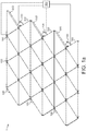
Figure 1a shows a cut-away perspective view of a part of a flooring system; -
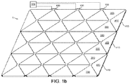
Figure 1b shows a perspective view of a part of a flooring system; -
Figure 2 shows a schematic representation of a plan view of a flooring system; -
Figure 3a shows a cut-away perspective view of a tile; -
Figure 3b shows a cut-away perspective view of an alternative tile; -
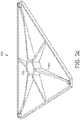
Figure 3c shows a perspective view of an frame of a tile; -
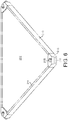
Figure 3d shows a perspective view of the underside of a tile; -
Figure 4 shows a perspective view of a tile; -
Figure 5 shows a perspective view of a tile; -
Figure 6 shows a perspective view of the underside of a tile; -
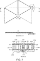
Figure 7 shows a cross-sectional view through two tiles; -
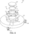
Figure 8 shows an exploded perspective view of part of a generator; -
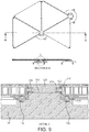
Figure 9 shows a cross-sectional view of a tile meeting a generator; -
Figure 10 shows a schematic representation of a time series generated by a flooring system; and -
Figure 11 shows a component of the flooring system. -
Figure 1a shows a first embodiment of a flooring system 1 for supporting one or more people and for generating electricity from the motion of those people as they walk across the flooring system. - The flooring system 1 comprises a plurality of
generators 100 and a plurality oftiles 200. The plurality oftiles 200 collectively define a floor surface for walking on. - Each
generator 100 comprises ahousing 105 and asupport 110. Thesupport 110 is movable with respect to thehousing 105. Eachgenerator 100 is arranged to generate electricity from linear motion of itssupport 110 in a first direction. Eachsupport 110 is biased towards a location in the first direction to provide a restoring force following displacement. When the flooring system 1 is installed, the first direction will correspond with the vertical direction, and eachsupport 110 will be biased by an upward force. The preferred form of thegenerator 100 is described in greater detail below. However, a generator having the form described inWO2011138585 could be used. - As can be seen from
Figures 1 and2 , eachsupport 110 supports a plurality oftiles 200. As a user walks across thetiles 200, thesupport 110 will be displaced from an equilibrium position. This will generate electricity using thegenerator 100. Thesupport 110 will then be returned to the equilibrium position by the biasing means (not shown). Thesupport 110 will move only over small distance so as to avoid an unpleasant sensation for the user. However, the cumulative effect of many steps from many users over a large area can generate a significant amount of electricity. - The
tiles 200 are pivotably support by eachsupport 110. It will be noted that this can prevent trip hazards from arising, since neighbouring tiles will move together. - In the arrangement of
Figure 1a , when a user steps on the flooring system, each footstep 2 will move thesupport 110 of one (e.g., if the footstep 2 lands on a generator 100), two (e.g., if the footstep 2 lands on the boundary between two neighbouring tiles 200), or three generators 100 (e.g., if the footstep 2 lands in the middle of a tile 200) . - The biasing means is preferably a spring, but could be provided by a magnetic device, or a combination of both.
- Similarly, each
tile 200 is supported by a plurality ofsupports 110. Thus, a user stepping on atile 200 can provide motion to each of thecorresponding supports 110, and thereby generate electricity via the corresponding plurality ofgenerators 100. In doing so, eachtile 200 will displace vertically and/or tilt by a small degree. - Each
tile 200 is generally planar with a firstmajor surface 201 and a secondmajor surface 202. The firstmajor surface 201 forms an upper surface in use. The secondmajor surface 202 forms a lower surface in use. - The
tiles 200 substantially tessellate to collectively form a substantially continuous floor surface. By "substantially" is meant that thetiles 200 do not meet exactly along each edge, but that a small gap is provided therebetween (to allow for relative rotation of neighbouring tiles 200). Furthermore eachtile 200 meets at agenerator 100, where a gap is provided between themultiple tiles 200 supported by thatgenerator 100. The gaps along each edge and at eachgenerator 100 are only small in comparison to the surface area of the floor surface taken up by thetiles 200, and so they can be said to substantially tessellate. - Preferably, the major surfaces of each tile is generally shaped as a triangle (most preferably, an equilateral triangle). By "generally shaped" is meant that the tile need not have perfectly sharp corners. As can be seen from
Figure 3 , the triangular shape may be slightly truncated in the corners. Since the corners are only truncated by a small amount, they can be said to be generally triangular. - Preferably, each
tile 200 is supported by exactly threesupports 110. That is, asupport 110 may support each corner of atile 200. Thetiles 200 are biased by the biasing means acting on thesupports 110 to be flat and level when a user is not standing on the floor surface. - By using this arrangement of
tiles 200, the possible degree of tilting of thetiles 200 may be larger than if other arrangements were used. For example, if a user steps on the corner of asquare tile 200, the opposite corner could protrude by a corresponding displacement. However, with triangular tiles, the movement of one corner represents the rotation of the tile about one edge, and so undesirable deformations of the floor, such as producing trip hazards, can be avoided for equivalent displacements. - The longest dimension of each
tile 200 is no more than 100cm. Preferably, the longest dimension of each tile is in the range 300mm to 700mm. - For a
square tile 200, the longest dimension would correspond to the distance between to opposite corners. - In the context of a generally
triangular tile 200, the longest dimension is the length of one edge. This substantially corresponds to the distance between supports 110. - For the flooring system 1 to allow sufficient motion, it is preferable that each
tile 200 has a thickness T that is as small as possible. This also reduces the need to excavate a large space for installation. However, the tiles must carry the weight of a user and so they must be rigid and strong. Thus, the inventors have designed the preferredcomposite tiles 200 shown inFigures 3a ,3b , and3c . - As shown in
Figure 3a , preferably, eachtile 200 comprises afirst sheet 206, and asecond sheet 207, and acore 205 sandwiched therebetween. - The
core 205 is preferably a non-continuous layer, such as a foam layer or a honeycomb layer. Thecore 205 may comprise a polymer. Alternatively, thecore 205 may comprise particles of wood and a resin. In some embodiments, thecore 205 may additionally or instead comprise: Nomex; polypropylene; chipboard; and/or fibre reinforced cement. - One or both of the
sheets sheets sheets - For ease of assembly, it is preferable that each tile comprises a
platform frame 211 that surrounds the perimeter of themajor surfaces - In more preferred embodiments, the platform may comprise a
further layer 235 on top of, or forming part of, thefirst sheet 206.Layer 235 may be formed of a preferred flooring material. Thislayer 235 may be decorative and/or resistant to damage from the footsteps of people walking over it. - When the
tiles 200 include aframe 211, thesupports 110 of thegenerators 100 preferably support theframes 211 of thetiles 200 directly. - Each
frame 211 is formed of frame members comprising anedge member 210 extending along each edge of themajor surfaces platform separate corner pieces 215 are provided, with theedge members 210 meeting at thecorner pieces 215. - As can be seen in
Figure 3c , the frame members are shaped so as to collectively define a seat in which the platform can be seated. - Each
edge member 210 may be formed as a strip from which afirst lip 211 protruding therefrom (for example, over all or a major portion of its length). Ifcorner pieces 215 are provided, these may be formed as a bent strip from which aweb 219 extends to form a seat. - With reference to
Figures 4 and6 , it can be seen that the corners of theframe 211 are provided with features for pivoting engagement between thetile 200 and thegenerator 100. In the particular embodiment shown the corners of theframe 211 are provided with features that also allow sliding between thetile 200 and thegenerator 100. Complementary features may be provided on thegenerator 100, as discussed below. - The corners of the
frame 211 preferably comprise arib 216 extending therefrom (preferably, parallel to themajor surfaces groove 217 is formed in the rib for reasons discussed below. - The corners of the
frame 211 preferably comprise anindent 218 on the underside thereof. Theindent 218 is preferably rounded. When seated upon a complementarily-shaped roller (as discussed below), theindent 218 can allow rotation of thetile 200 in multiple degrees of freedom. In fact, theindent 218 is also elongated to allow sliding motion. - As can be seen in
Figure 3d , thetile 200 may be provided with reinforcingribs 290 to provide extra rigidity. Preferably, acentral stop 292 is also provided. Thecentral stop 292 is arranged to contact with the ground if too great a force is applied to thetile 200. In this way, thegenerator 100 may be protected. Theribs 290 and stop 292 may be formed as part of theframe 211 or the platform. - Preferably, a
flexible sealing strip 230 is provided between the neighbouring edges of eachadjacent tile 200. This can prevent the ingress of most solid materials (and, in some cases, liquids) into the area below the floor. Furthermore, and equally importantly, the sealingstrip 230 acts to prevent a direct impact betweenadjacent tiles 200. Thetiles 200 are rigid and so contact would produce noise as a user walks across the flooring system 1. - With reference to
Figure 7 , there can be seen a cross-sectional view of twotiles first sheet 206, asecond sheet 207, acore 205, and afurther layer 235 of flooring material. Aflexible sealing strip 230 extends between the twotiles 200. - For the
first tile 200a, the strip of theframe member 210a extends from the firstmajor surface 201 such that it is flush with the surface of theflooring material layer 235. Thus, the frame can protect thelayer 235. Thelip 211a provides a support for the platform. The strip of theframe member 210a extends below the level of thelip 211a. Extending outwardly from the strip in the opposite direction fromlip 211a, and positioned further from themajor surface 202 of the tile, is a supportingflange 212. The supportingflange 212 may extend over all or a major portion of the length of the strip. - It is possible for all frames to include a supporting
flange 212. However, it is preferred that each sealingstrip 230 is supported by only a single supportingflange 212. The simplest way to achieve this is by including two types oftile tile 200a includes a supportingflange 212 along every edge, while the second type oftile 200b does not include a supportingflange 212. The two types oftile tile 200 everyadjacent tile 200 is of a different type. - In this example, for the
second tile 200b, the strip forming theframe member 210b also extends from the firstmajor surface 201 such that it is flush with the surface of theflooring material layer 235. However, the strip for thistile 200b extends only as far aslip 211b on which the platform is seated. The supportingflange 212 of the strip of thefirst tile 200a extends below the strip of thesecond tile 200b by a distance G. - Every other tile may have
edge members 210 formed with asecond lip 211 protruding from the strip (for example, over all or a major portion of its length). - The supporting flanges are used to support the flexible sealing strips 230. The
flexible sealing strip 230 is formed of a compressible material to not hinder the relative movement of the neighbouringtiles 200. Thestrip 230 may comprise or be formed of: rubber; neoprene; TPV; TPE; and/or polymeric materials. - An array of
generators 100 is provided. Thegenerators 100 are preferably provided in a regular array so as to support the corners of thetiles 200. Other arrangements can be used (for example, the generators could be provided at the midpoints of the edges of the tiles), but the disclosed arrangement is preferable. - The corners of
multiple tiles 200 tiles sit on asingle support 110. In the preferred embodiment sixtiles 200 sit on eachsupport 110. - As can be seen in
Figure 8 , eachgenerator 100 comprises anhousing 105, having anaperture 107 through which part of thesupport 110 extends. Thegenerator 100 may comprise two or moreadjustable feet 123 extending from thehousing 105 to enable its height and orientation to be adjusted. - The
generator 100 may be an electromagnetic generator comprising a rotor (not shown) that rotates about an axis parallel with the first direction. The rotor may be driven to rotate by motion of thesupport 110 in the first direction. Suitable arrangements of magnets and coils may be provided (not shown) to generate electricity from the rotation of the rotor.WO2011138585 discloses an optional form of generator. - It has been found through significant efforts that in order to provide the user with a suitable experience, the range of movement of each
support 110 in the first direction should be limited to by no more than 20mm. Preferably, the range of movement should be in the range 5mm to 10mm. - Each
generator 100 may comprise a biasing means such as one or more spring(s) for biasing thesupport 110 in the first direction to a nominal position. Alternatively, or in addition, the biasing means may be provided separately from eachgenerator 100. If the biasing means act directly on thetiles 200 to level thetiles 200 when the floor surface is not carrying the weight of a user, then they will necessarily bias thesupports 110 back to the nominal positions. - Each
support 110 comprises a plurality of pivots via which eachtile 200 is supported, wherein each pivot allows onetile 200 to tilt relative to thesupport 100, and preferably also to slide relative to thesupport 100. - Preferably, each
support 110 comprises aplatform 111 upon which is located agasket 112. Thegasket 112 is preferably made of resilient material to muffle the sound of footsteps. Preferably, thegasket 112 comprises or is formed of: rubber; neoprene; TPV; TPE; and/or a polymeric material. - The
tiles 200 are supported on thegasket 112. - In preferred embodiments, the
gasket 112 comprises a plurality ofrollers 116. Therollers 116 may be seated in complementarily-shapedindents 113 in theplatform 111. Rollers may be any suitable shape, e.g. cylindrical, but are preferably spherical or generally spherical. Therollers 116 are complementary to theindents 218 in thetiles 200 described above. Therollers 116 and indents 113, 218 can allow rotation of thetile 200 in multiple degrees of freedom. - Preferably, one
roller 116 is provided pertile 200. (That is, in the preferred embodiment, six would be provided on each support 110). - As shown in the preferred embodiment of
Figures 8 and9 , thesupport 110 may comprise aneck 114 extending from theplatform 111. Thegasket 112 may comprise asleeve 117 with aflange 115 extending from the base thereof. Thesleeve 117 fits around theneck 114 of thesupport 110 with theflange 115 resting on the surface of theplatform 111. Therollers 116 are formed in the flange. - Each
roller 116 may be a separate article rotating about a shaft of theflange 115. However, since the amount of movement of theroller 116 need not be great, it may be manufactured integrally with theflange gasket 112. For example, theroller 116 may be linked to theflange 115 of thegasket 112 via a resilient web (e.g., a narrow web of thegasket 112 material) that twists and/or stretches as theroller 116 rotates. - In order to restrain vertical motion of each
tile 200 and to ensure that the edges of everytile 200 are aligned, acap 120 may be provided. Thecap 120 may prevent thetile 200 from translating relative to thesupport 110 in the first direction. Thecap 120 may be fixed to the support 110 (for example, theneck 114 of the support 110) by any fixing means (e.g., by screws). In order to prevent the hard tile from contacting thehard cap 120, an O-ring 122 and/or further gasket made from resilient materials may be provided therebetween. Preferably, the O-ring 122 or further gasket comprises or is formed of: rubber; neoprene; TPV; TPE; and/or a polymeric material. -
Figure 9 shows a cross-section through the corners of twotiles 200 at agenerator 100 through tworollers 116. As can be seen, therigid tiles 200 do not contact the rigid components of thesupport 110 orcap 120 directly, but are supported by the resilient materials of thegasket 112 and O-ring 122. - In this preferable arrangement,
rib 216 extending from the corners of theframe 211 engages the underside of thecap 120 via the O-ring 122 or gasket, while the underside of theframe 211 sits on thegasket 112. When an O-ring 122 is provided, thegroove 217 formed in therib 216 corresponds to the shape of the O-ring 122. - In assembling the flooring system 1, the
frames 211 andgenerators 100 can be installed first. Then the height and level of thegenerators 100 may be adjusted until theframes 211 are all level. The platforms of thetiles 200 may then be placed into theframes 211. The height and level of thegenerators 100 may be adjusted using thefeet 123. Theseals 230 may then be inserted between neighbouring tiles. - As can be seen from
Figure 1b , at the boundary of the flooring systemadditional tiles 400 of a different shape may be provided. These may be pivotably attached 410 to other flooring to provide a smooth transition between the system of the invention and conventional flooring. - The inventors have realised that the flooring system 1 can be used, in addition to generating electricity, to collect data about the presence and/or movement of people across the flooring system 1.
- The flooring system 1 may comprise a
data processing system 300 in communication with each generator for receiving the electrical power generated thereby. - Firstly, it has been found that an appropriately accurate estimate of person occupancy of an area of the flooring system 1 can be determined based on the power output of the floor as a whole.
- For a given selection of generators, their arrangement, and the arrangement of tiles, an average power output per user can be determined. For example, under controlled conditions a number of people can be instructed to walk across the floor, and the power output measured. The measured power can be averaged over time and divided by the number of people to provide the average power output per person. This predetermined value can be stored by the system 1.
- Thus, in order to monitor the occupancy of an area, the
data processing system 300 is arranged to estimate the number of people supported by the plurality of tiles by: calculating a total power output of the plurality of generators; and dividing the total output by the stored predetermined value. - The occurrence of a footstep 2 on a
tile 200 can be noted by thedata processing system 300. The identification of atile 200 as it is contacted by a footstep 2 may be stored by thedata processing system 300. Thus, thedata processing system 300 may record the time and location (the particular tile 200) of each footstep 2. - With reference to
Figure 2 , the inventors have also realised that the support of atile 200x using three ormore generators particular tile 200 the flooring system 1. - During a footstep, the electrical signal generated by each of the three
generators generators 100 can be recorded. If the footstep is closer to onegenerator 100 than another, then that generator will generate a greater voltage. By comparing the voltages provided by thegenerators tile 200x it is possible to identify the relative distance between thegenerators 100, and thereby determine the location of the footstep 2 (i.e., the centre of gravity of the footstep 2) on eachtile 200. - Moreover, with the preferred form of
generator 100 described above, an electromagnetic generator comprising a rotor that rotates about an axis, it is possible to provide a signal representing the speed of rotation (or rotational frequency) of the rotor. This can also provide an indication of a footstep 2. In any of the above cases, thegenerator 100 can be configured to generate a signal representing a force applied to thegenerator 100 by thetile 200. - During a footstep, the signal generated by each of the three
generators Figure 10 . For example, in a typical footstep, as a user's foot contacts atile 200, the foot will firstly impact on the heel and then roll towards the ball of the foot. For each of the threegenerators generator - The
data processing system 300 is arranged to determine a time difference between the signals received from thegenerators 100 supporting thattile 200 to estimate the direction of the user's motion. - Preferably, the
data processing system 300 is arranged to determine the order in which the signals received from thegenerators 100 supporting thattile 200 reach a maximum value. The order in which thegenerators - It can be therefore seen from the description above that the flooring system 1 can provide an estimate of location of a footstep (either coarsely, identifying a particular tile, or more accurately, identifying the location on that tile) and its direction.
- Moreover, based on the magnitude of the footstep 2 (e.g., the energy generated by a single step), the size of a user may be estimated. This can be configured by instructing users of known mass to walk across the flooring system 1 and carrying out appropriate measurements.
- For a more accurate estimate of the size of a user, the user's speed may be taken into account. A user running can generate more energy than a user walking slowly. Speed may be derived from the output of a tracking algorithm (discussed below), the duration of the footstep 2, and/or the time series data for each footstep 2 (which characterises the variation in footstep force over time). Again, this can be configured by instructing users of known mass to walk across the flooring system 1 at a known pace and carrying out appropriate measurements.
- The occurrence of a footstep 2 on a
tile 200 can be noted by thedata processing system 300, which may apply a tracking algorithm to track the passage of a walker across the flooring system 1. For example, the arrangement of thetiles 200 may be stored in thedata processing system 300. The identification of atile 200 as it is contacted by a footstep 2 may be provided as an input to a tracking algorithm, which may be configured to track the path of the user walking across the flooring system 1. That is, thedata processing system 300 may record the time and location of each footstep 2, and will label each footstep 2 as corresponding to the same user as another footstep 2. Suitable tracking algorithms are well known in the art, and include, for example: Kalman filters; and/or probability hypothesis density tracker. - The identification of a
tile 200 as it is contacted by a footstep 2 may be supplemented with time series data representing the time series output of eachgenerator 100 corresponding to thetile 200 to provide as an input to a tracking algorithm. - However, the inventors have found that the additional data "preprocessing" steps set out above can be used in a tracking algorithm at lower computational expense.
- It is also preferable to time stamp the data provided to the tracker.
- Preferably, the input to the tracking algorithm is the location of a footstep 2 and the direction of the footstep 2.
- More preferably, the input to the tracking algorithm is one or more of: the location of a footstep 2, the direction of the footstep 2, the magnitude (power or energy) of the footstep, and data representing an estimate of the mass of the user.
- Preferably, the
generators 100 provide an output signal representing the force applied periodically, after a time period of from 10ms to 50ms. - In some embodiments, the output signal may be triggered by a footstep and last for between 250ms and 750ms, preferably 500ms.
- The
data processing system 300 can therefore output an estimate of one or more of: - occupancy of a selected area;
- the raw track representing the path of one or more users across the flooring system 1;
- the average walking speed of the group of users (this can be derived by dividing path length by time); and/or
- the average number of people in a given period of time passing through a predetermined location.
- As will be appreciated by one skilled in the art, whilst it is preferable to use generators to harvest energy from the flooring system 1, the advantages of the tracking methodology would be available if the generators were simply replaced with some form of pressure sensor, such as a piezo-electric sensor. Indeed, in this context, the generator can be thought of as a sensor.
- In a further alternative embodiment, the flooring system 1 may additionally comprise a plurality of electromagnetic receivers for receiving identifiers transmitted by mobile communications devices and for identifying the strength of reception of each of the identifiers. Preferably, each receiver is located in the space below the corresponding
tile 200. - Preferably, the receivers are arranged to receive identifiers transmitted by mobile phones (cell phones). For example, the receivers are arranged to receive RFID, Bluetooth or Zigbee signals identifying a mobile phones.
- In response to a force applied to a
tile 200, the sensors are arranged to activate the receiver corresponding to thattile 200. - The receiver can receive multiple transmitted identifiers measure the strength of reception corresponding to each transmission. The system assumes that the greatest strength of reception can correspond to the mobile communications device carried by the user that stepped on the
tile 200. - Thus, when activated, the receiver is arranged to receive any transmitted identifiers and to determine the identifier corresponding to the reception of greatest strength.
- The
data processing system 300 is in communication with each sensor and each receiver, and is arranged to generate data representing the time at which the force was sensed, thetile 200 to which the force was applied, and the determined identifier received by the receiver corresponding to thattile 200. One or each of these data can be used to supplement the input to the tracker. - It is noted that if a user is not carrying a mobile communications device, then the received identifier would be incorrect. However, using an appropriate tracking algorithm (e.g., a probabilistic tracker such as a Kalman Filter), this error can be easily disregarded. On the other hand, when the received identifier is correct, this provides a great improvement in the performance of the tracking algorithm.
- In a similar embodiment, the flooring system 1 does not receive from the user. Instead each tile has associated therewith a transmitter that transmits a signal (for example, a code denoting its own identity).
- Such a flooring system 1 comprises: a central receiver for receiving identifiers transmitted by mobile communications devices; a plurality of tiles for supporting one or more people, each tile coupled to one or more sensors for sensing a force applied to the tile; and a plurality of electromagnetic transmitters for transmitting a signal for illiciting a response from a mobile communications device, each transmitter corresponding to a respective tile,
wherein: in response to a force applied to a tile the sensors are arranged to activate the transmitter corresponding to that tile, wherein: the flooring system further comprising a data processing system, in communication with each sensor and the receiver; and the data processing system is arranged to generate output data representing the time at which the force was sensed, the tile to which the force was applied, and the determined identifier received by the receiver. - Preferably, the transmitter is located below the corresponding tile and the electromagnetic receiver is arranged to receive identifiers transmitted by mobile telephones. The mobile telephone may have thereon software (e.g., an app), programmed to respond to the receipt of the transmission by sending an identifying code to the central receiver.
-
Figure 11 shows a base 600 upon which the flooring system 1 can be installed. Thebase 600 comprises a plurality of slabs 500 (preferably formed of or comprising concrete). - Each
slab 500 includes a raisedpedestal 510 on which agenerator 100 of the flooring system 1 may be placed. Drainage holes 535 are also provided to provide a path for the egress of liquid on thebase 600. Any liquid spilled upon the flooring system 1 that passes the sealing strips, O-rings, and/or gaskets, will thus not pool around agenerator 100. Moreover, theslabs 500 may be provided with an inclined upper surface, sloping away from thepedestals 510 and towards the drainage holes 535, so that gravity draws the liquid away from thepedestals 510. - The
slabs 500 may include interlocking features 515, 520, 525 to enable eachslab 500 to interlock with anotherslab 500. - Preferably, each
slab 500 comprises a plurality oftabs 515 and a plurality of complementarily-shapedcavities 540 spaced along two or more edges. Thetabs 515 preferably have a trapezium shape such that thecavities 540 are defined therebetween. - Preferably, one or
more drainage holes 535 are provided in one, more or all of thetabs 515. - Preferably, each slab comprises a plurality of
pedestals 510 spaced in a line that terminates at one end in atab 520 and another end in a complementarily-shapedcavity 525.
Claims (15)
- A flooring system (1) for generating electricity, comprising:a plurality of generators (100), each generator having a support (110), each generator (100) being arranged to generate electricity from linear motion of the support (110) in a first direction; anda plurality of tiles (200) for supporting one or more people, characterised in that:each support (110) supports a plurality of tiles (200); andthe major surfaces of each tile (200) are generally shaped as a triangle.
- The flooring system (1) of claim 1, wherein each tile (200) is supported by a plurality of supports (110).
- The flooring system (1) of any preceding claim, wherein each tile (200) is pivotably and/or slidably supported by each support (110).
- The flooring system (1) of any preceding claim, wherein each tile (200) is supported by exactly three supports (110).
- The flooring system (1) of any preceding claim, wherein the tiles (200) substantially tessellate to collectively form a substantially continuous surface.
- The flooring system (1) of any preceding claim, wherein the major surfaces of each tile (200) is generally shaped as an equilateral triangle.
- The flooring system (1) of any preceding claim, wherein the longest dimension of each tile (200) no more than 100cm.
- The flooring system (1) of any preceding claim, wherein the longest dimension of each tile (200) is in the range 30cm to 70cm.
- The flooring system (1) of any preceding claim, wherein each of the plurality of generators (100) is an electromagnetic generator comprising a rotor that rotates about an axis parallel with the first direction.
- The flooring system (1) of any preceding claim, wherein the support of each of the plurality of generators (100) is movable in the first direction by no more than 20mm.
- The flooring system (1) of any preceding claim, wherein the support of each of the plurality of generators (100) is movable in the first direction by an amount in the range 5mm to 10mm.
- The flooring system (1) of any preceding claim, wherein each support (110) comprises a plurality of pivots via which the tiles (200) are supported, wherein the pivots allow the tiles (200) to tilt relative to the support.
- The flooring system (1) of any preceding claim, wherein each support (110) comprises a cap for restraining vertical motion of a tile (200) relative to the support (110).
- The flooring system (1) of any preceding claim, further comprising a plurality of flexible sealing strips (230), each flexible sealing strips (230) extending along the neighbouring edges of two adjacent tiles (200).
- The flooring system (1) of claim 14, wherein the flexible sealing strips (230) are formed from or comprise rubber; neoprene; TPV; TPE; and/or other polymeric materials.
Applications Claiming Priority (2)
| Application Number | Priority Date | Filing Date | Title |
|---|---|---|---|
| GB1516234.0A GB2542203B (en) | 2015-09-14 | 2015-09-14 | Flooring system |
| PCT/GB2016/052844 WO2017046586A1 (en) | 2015-09-14 | 2016-09-14 | Flooring system |
Publications (2)
| Publication Number | Publication Date |
|---|---|
| EP3350439A1 EP3350439A1 (en) | 2018-07-25 |
| EP3350439B1 true EP3350439B1 (en) | 2020-03-11 |
Family
ID=54363124
Family Applications (1)
| Application Number | Title | Priority Date | Filing Date |
|---|---|---|---|
| EP16770312.3A Active EP3350439B1 (en) | 2015-09-14 | 2016-09-14 | Flooring system |
Country Status (5)
| Country | Link |
|---|---|
| US (1) | US10557460B2 (en) |
| EP (1) | EP3350439B1 (en) |
| CN (1) | CN108431410B (en) |
| GB (1) | GB2542203B (en) |
| WO (1) | WO2017046586A1 (en) |
Families Citing this family (12)
| Publication number | Priority date | Publication date | Assignee | Title |
|---|---|---|---|---|
| US9158369B2 (en) * | 2010-10-12 | 2015-10-13 | Tactonic Technologies, Llc | Sensors having a connecting frame and method for composite sensors |
| GB2558174B (en) | 2016-05-10 | 2019-05-08 | Pavegen Systems Ltd | Electrical generator |
| USD860999S1 (en) * | 2018-08-07 | 2019-09-24 | Spigen Korea Co., Ltd. | Case for tablet computer |
| US11063415B2 (en) * | 2019-01-16 | 2021-07-13 | Raymond & Lae Engineering, Inc. | Raised access floor panel with embedded sensors |
| US11193284B2 (en) * | 2019-05-21 | 2021-12-07 | Silca System, Llc | Tile-securing system and related methods |
| US10927554B1 (en) * | 2019-07-11 | 2021-02-23 | Donald L. Kimble | Modular detectable warning surface tile, frame, and assembly |
| CN110927483B (en) * | 2019-11-08 | 2021-10-08 | 杭州电子科技大学 | A test bench for power generation floor tiles and its testing method |
| CN113100721B (en) * | 2021-03-04 | 2022-10-04 | 浙江慧养科技有限公司 | Intelligent home decoration floor capable of collecting human heart rate and respiration signals |
| KR102550181B1 (en) * | 2021-03-29 | 2023-06-29 | 한국세라믹기술원 | Foot mat type piezoelectric power module |
| US12391400B2 (en) | 2021-09-01 | 2025-08-19 | B/E Aerospace (Uk) Limited | Systems and methods for power generation in aircraft cabins |
| CN113916058B (en) * | 2021-11-08 | 2023-09-01 | 娄少回 | Remote restraint device and panel, movable stay bar and support seat thereof |
| TWI878088B (en) * | 2024-04-11 | 2025-03-21 | 李燕瑟 | Pedal power generation structure |
Family Cites Families (29)
| Publication number | Priority date | Publication date | Assignee | Title |
|---|---|---|---|---|
| US4295066A (en) * | 1980-01-11 | 1981-10-13 | Cts Corporation | Electromagnetic actuator |
| US4614875A (en) * | 1985-01-31 | 1986-09-30 | Mcgee Terrill A | Vehicle actuated, roadway electrical generator |
| US5347186A (en) * | 1992-05-26 | 1994-09-13 | Mcq Associates, Inc. | Linear motion electric power generator |
| EP1127541B1 (en) | 2000-02-18 | 2004-02-11 | RsScan International | A method and apparatus for determining a flexural property of a load applied to a discretely sampled pressure sensor array |
| US7102244B2 (en) * | 2002-10-03 | 2006-09-05 | Hunter Jr John P | Vehicle actuated road imbedded magneto generator |
| NL1022568C2 (en) * | 2003-02-03 | 2004-09-14 | Zoontjes Beton B V | Support for a tiled floor. |
| US7432607B2 (en) * | 2006-05-08 | 2008-10-07 | Kim Richard H | Power generation pad using wasted energy |
| US7698860B2 (en) * | 2006-08-31 | 2010-04-20 | Stageright Corporation | Raised deck system for emergency isolation and treatment shelter (EITS) |
| WO2008127823A1 (en) * | 2007-04-12 | 2008-10-23 | Faramarz Frank Ghassemi | Electro gravity plates for generating electricity from passage of vehicles over the plates |
| NL1034439C1 (en) | 2007-09-28 | 2009-03-31 | Sustainable Dance Club B V | Floor. |
| JP5808518B2 (en) * | 2008-11-28 | 2015-11-10 | ジェイアール東日本コンサルタンツ株式会社 | Power generation member, power generation apparatus and power generation system using the same |
| EP2425068B1 (en) | 2009-04-27 | 2015-06-03 | Mohawk Carpet Corporation | Flooring systems and methods of using same |
| CN201661047U (en) | 2010-01-26 | 2010-12-01 | 陈建明 | Vibration power generation floor |
| JP4912477B2 (en) | 2010-02-02 | 2012-04-11 | 公立大学法人高知工科大学 | Mobile floor reaction force measuring device |
| US8330283B2 (en) * | 2010-03-22 | 2012-12-11 | Ming-Sheng Lin | Underground generating device that is rolled or run over by cars so as to provide a generating effect |
| GB201007497D0 (en) * | 2010-05-05 | 2010-06-23 | Pavegen Systems Ltd | Energy harvesting |
| FR2972773B3 (en) * | 2011-03-18 | 2013-03-29 | Viha Concept | POWER GENERATING DEVICE USING MOTION ENERGY, INTEGRATED TO A SIDEWALK OR ROAD FOR LOCAL USE |
| WO2011151402A2 (en) * | 2010-06-01 | 2011-12-08 | Viha Concept | Energy generation device using motion energy capable of being incorporated into a sidewalk or a road for local use |
| FR2971561A1 (en) * | 2011-02-15 | 2012-08-17 | Viha Concept | Energy production device for use at e.g. sidewalk to supply energy to public lighting, has upper and lower parts connected by magnetized bar for sliding within induction coil when upper part moves relative to lower part |
| MY161953A (en) | 2010-09-09 | 2017-05-15 | Amcorp Sendirian Berhad | Energy conversion device |
| DE102010052048B4 (en) * | 2010-11-23 | 2015-03-26 | Hans Markert | disk system |
| US8791584B2 (en) * | 2011-06-14 | 2014-07-29 | Charles Martin Sieger | Structurally integrated electric/heat generating energy recovery (SIEGER) |
| FR2988119B1 (en) * | 2012-03-13 | 2015-12-25 | Soprema | COATING ELEMENT, IN PARTICULAR FOR ROOF AND TERRACE |
| US10041254B2 (en) * | 2013-10-25 | 2018-08-07 | Mbrico, Llc | Tile and support structure |
| CN104763599A (en) | 2014-01-02 | 2015-07-08 | 达胡巴雅尔 | pressure conversion power generation device |
| DE102014107485B4 (en) * | 2014-05-27 | 2018-05-03 | Norbert Gerberich | Tile covering for placement on a floor |
| US9691240B2 (en) * | 2015-01-22 | 2017-06-27 | Interface, Inc. | Floor covering system with sensors |
| IT201600081448A1 (en) * | 2016-08-03 | 2018-02-03 | Progress Profiles Spa | PROFILE FOR THE LAYING OF RAISED FLOORS AND RAISED FLOOR INCLUDING THIS PROFILE |
| CN108539923A (en) * | 2018-05-03 | 2018-09-14 | 北京触动力科技有限公司 | Power generator, electrification component and electricity-generating method |
-
2015
- 2015-09-14 GB GB1516234.0A patent/GB2542203B/en active Active
-
2016
- 2016-09-14 EP EP16770312.3A patent/EP3350439B1/en active Active
- 2016-09-14 WO PCT/GB2016/052844 patent/WO2017046586A1/en not_active Ceased
- 2016-09-14 CN CN201680060196.0A patent/CN108431410B/en active Active
- 2016-09-14 US US15/759,741 patent/US10557460B2/en active Active
Non-Patent Citations (1)
| Title |
|---|
| None * |
Also Published As
| Publication number | Publication date |
|---|---|
| CN108431410A (en) | 2018-08-21 |
| CN108431410B (en) | 2020-04-14 |
| GB201516234D0 (en) | 2015-10-28 |
| US10557460B2 (en) | 2020-02-11 |
| GB2542203B (en) | 2018-01-17 |
| US20190048858A1 (en) | 2019-02-14 |
| GB2542203A (en) | 2017-03-15 |
| WO2017046586A1 (en) | 2017-03-23 |
| EP3350439A1 (en) | 2018-07-25 |
Similar Documents
| Publication | Publication Date | Title |
|---|---|---|
| US10557460B2 (en) | Flooring system | |
| GB2542204B (en) | Flooring system | |
| EP2425068B1 (en) | Flooring systems and methods of using same | |
| US9619987B2 (en) | Floor covering | |
| US7916035B2 (en) | Device for a bed alarm | |
| US9022912B2 (en) | Step platform for slow step exercises | |
| EP1209301A3 (en) | Parquet underlay material | |
| NZ588821A (en) | Concrete floor grating unit with elastic insert elements | |
| Banerjee et al. | Improving floor localization accuracy in 3D spaces using barometer | |
| US20180023305A1 (en) | Weight lifting station | |
| US20060107480A1 (en) | Door mat | |
| EP0373724B1 (en) | Method and anchoring plate material for keeping a readily removable mat or the like small carpet in place | |
| WO2013171709A1 (en) | A sensing covering system | |
| US11309769B2 (en) | Method and system for generating electricity from footsteps | |
| CA2691432C (en) | Water draining foot mat | |
| JP2690274B2 (en) | Sunoko | |
| US5136771A (en) | Method of keeping an easily removable mat or the like small carpet in place | |
| AU2018101482A4 (en) | Alltac Sirius Large Format Plastic Plate | |
| WO2024010577A1 (en) | Leveling spacer for tiles | |
| GB2595737A (en) | Floor mat | |
| KR20180036214A (en) | Mat for non-slip and preventing a foreign substance being jammed |
Legal Events
| Date | Code | Title | Description |
|---|---|---|---|
| STAA | Information on the status of an ep patent application or granted ep patent |
Free format text: STATUS: THE INTERNATIONAL PUBLICATION HAS BEEN MADE |
|
| PUAI | Public reference made under article 153(3) epc to a published international application that has entered the european phase |
Free format text: ORIGINAL CODE: 0009012 |
|
| STAA | Information on the status of an ep patent application or granted ep patent |
Free format text: STATUS: REQUEST FOR EXAMINATION WAS MADE |
|
| 17P | Request for examination filed |
Effective date: 20180413 |
|
| AK | Designated contracting states |
Kind code of ref document: A1 Designated state(s): AL AT BE BG CH CY CZ DE DK EE ES FI FR GB GR HR HU IE IS IT LI LT LU LV MC MK MT NL NO PL PT RO RS SE SI SK SM TR |
|
| AX | Request for extension of the european patent |
Extension state: BA ME |
|
| DAV | Request for validation of the european patent (deleted) | ||
| DAX | Request for extension of the european patent (deleted) | ||
| STAA | Information on the status of an ep patent application or granted ep patent |
Free format text: STATUS: EXAMINATION IS IN PROGRESS |
|
| 17Q | First examination report despatched |
Effective date: 20190128 |
|
| GRAP | Despatch of communication of intention to grant a patent |
Free format text: ORIGINAL CODE: EPIDOSNIGR1 |
|
| STAA | Information on the status of an ep patent application or granted ep patent |
Free format text: STATUS: GRANT OF PATENT IS INTENDED |
|
| INTG | Intention to grant announced |
Effective date: 20190927 |
|
| GRAS | Grant fee paid |
Free format text: ORIGINAL CODE: EPIDOSNIGR3 |
|
| GRAA | (expected) grant |
Free format text: ORIGINAL CODE: 0009210 |
|
| STAA | Information on the status of an ep patent application or granted ep patent |
Free format text: STATUS: THE PATENT HAS BEEN GRANTED |
|
| AK | Designated contracting states |
Kind code of ref document: B1 Designated state(s): AL AT BE BG CH CY CZ DE DK EE ES FI FR GB GR HR HU IE IS IT LI LT LU LV MC MK MT NL NO PL PT RO RS SE SI SK SM TR |
|
| REG | Reference to a national code |
Ref country code: GB Ref legal event code: FG4D |
|
| REG | Reference to a national code |
Ref country code: CH Ref legal event code: EP |
|
| REG | Reference to a national code |
Ref country code: AT Ref legal event code: REF Ref document number: 1243438 Country of ref document: AT Kind code of ref document: T Effective date: 20200315 |
|
| REG | Reference to a national code |
Ref country code: IE Ref legal event code: FG4D |
|
| REG | Reference to a national code |
Ref country code: DE Ref legal event code: R096 Ref document number: 602016031589 Country of ref document: DE |
|
| REG | Reference to a national code |
Ref country code: NL Ref legal event code: FP |
|
| PG25 | Lapsed in a contracting state [announced via postgrant information from national office to epo] |
Ref country code: NO Free format text: LAPSE BECAUSE OF FAILURE TO SUBMIT A TRANSLATION OF THE DESCRIPTION OR TO PAY THE FEE WITHIN THE PRESCRIBED TIME-LIMIT Effective date: 20200611 Ref country code: FI Free format text: LAPSE BECAUSE OF FAILURE TO SUBMIT A TRANSLATION OF THE DESCRIPTION OR TO PAY THE FEE WITHIN THE PRESCRIBED TIME-LIMIT Effective date: 20200311 Ref country code: RS Free format text: LAPSE BECAUSE OF FAILURE TO SUBMIT A TRANSLATION OF THE DESCRIPTION OR TO PAY THE FEE WITHIN THE PRESCRIBED TIME-LIMIT Effective date: 20200311 |
|
| PG25 | Lapsed in a contracting state [announced via postgrant information from national office to epo] |
Ref country code: LV Free format text: LAPSE BECAUSE OF FAILURE TO SUBMIT A TRANSLATION OF THE DESCRIPTION OR TO PAY THE FEE WITHIN THE PRESCRIBED TIME-LIMIT Effective date: 20200311 Ref country code: SE Free format text: LAPSE BECAUSE OF FAILURE TO SUBMIT A TRANSLATION OF THE DESCRIPTION OR TO PAY THE FEE WITHIN THE PRESCRIBED TIME-LIMIT Effective date: 20200311 Ref country code: HR Free format text: LAPSE BECAUSE OF FAILURE TO SUBMIT A TRANSLATION OF THE DESCRIPTION OR TO PAY THE FEE WITHIN THE PRESCRIBED TIME-LIMIT Effective date: 20200311 Ref country code: GR Free format text: LAPSE BECAUSE OF FAILURE TO SUBMIT A TRANSLATION OF THE DESCRIPTION OR TO PAY THE FEE WITHIN THE PRESCRIBED TIME-LIMIT Effective date: 20200612 Ref country code: BG Free format text: LAPSE BECAUSE OF FAILURE TO SUBMIT A TRANSLATION OF THE DESCRIPTION OR TO PAY THE FEE WITHIN THE PRESCRIBED TIME-LIMIT Effective date: 20200611 |
|
| REG | Reference to a national code |
Ref country code: LT Ref legal event code: MG4D |
|
| PG25 | Lapsed in a contracting state [announced via postgrant information from national office to epo] |
Ref country code: LT Free format text: LAPSE BECAUSE OF FAILURE TO SUBMIT A TRANSLATION OF THE DESCRIPTION OR TO PAY THE FEE WITHIN THE PRESCRIBED TIME-LIMIT Effective date: 20200311 Ref country code: EE Free format text: LAPSE BECAUSE OF FAILURE TO SUBMIT A TRANSLATION OF THE DESCRIPTION OR TO PAY THE FEE WITHIN THE PRESCRIBED TIME-LIMIT Effective date: 20200311 Ref country code: SM Free format text: LAPSE BECAUSE OF FAILURE TO SUBMIT A TRANSLATION OF THE DESCRIPTION OR TO PAY THE FEE WITHIN THE PRESCRIBED TIME-LIMIT Effective date: 20200311 Ref country code: RO Free format text: LAPSE BECAUSE OF FAILURE TO SUBMIT A TRANSLATION OF THE DESCRIPTION OR TO PAY THE FEE WITHIN THE PRESCRIBED TIME-LIMIT Effective date: 20200311 Ref country code: PT Free format text: LAPSE BECAUSE OF FAILURE TO SUBMIT A TRANSLATION OF THE DESCRIPTION OR TO PAY THE FEE WITHIN THE PRESCRIBED TIME-LIMIT Effective date: 20200805 Ref country code: CZ Free format text: LAPSE BECAUSE OF FAILURE TO SUBMIT A TRANSLATION OF THE DESCRIPTION OR TO PAY THE FEE WITHIN THE PRESCRIBED TIME-LIMIT Effective date: 20200311 Ref country code: IS Free format text: LAPSE BECAUSE OF FAILURE TO SUBMIT A TRANSLATION OF THE DESCRIPTION OR TO PAY THE FEE WITHIN THE PRESCRIBED TIME-LIMIT Effective date: 20200711 Ref country code: SK Free format text: LAPSE BECAUSE OF FAILURE TO SUBMIT A TRANSLATION OF THE DESCRIPTION OR TO PAY THE FEE WITHIN THE PRESCRIBED TIME-LIMIT Effective date: 20200311 |
|
| REG | Reference to a national code |
Ref country code: AT Ref legal event code: MK05 Ref document number: 1243438 Country of ref document: AT Kind code of ref document: T Effective date: 20200311 |
|
| REG | Reference to a national code |
Ref country code: DE Ref legal event code: R097 Ref document number: 602016031589 Country of ref document: DE |
|
| PLBE | No opposition filed within time limit |
Free format text: ORIGINAL CODE: 0009261 |
|
| STAA | Information on the status of an ep patent application or granted ep patent |
Free format text: STATUS: NO OPPOSITION FILED WITHIN TIME LIMIT |
|
| PG25 | Lapsed in a contracting state [announced via postgrant information from national office to epo] |
Ref country code: ES Free format text: LAPSE BECAUSE OF FAILURE TO SUBMIT A TRANSLATION OF THE DESCRIPTION OR TO PAY THE FEE WITHIN THE PRESCRIBED TIME-LIMIT Effective date: 20200311 Ref country code: DK Free format text: LAPSE BECAUSE OF FAILURE TO SUBMIT A TRANSLATION OF THE DESCRIPTION OR TO PAY THE FEE WITHIN THE PRESCRIBED TIME-LIMIT Effective date: 20200311 Ref country code: AT Free format text: LAPSE BECAUSE OF FAILURE TO SUBMIT A TRANSLATION OF THE DESCRIPTION OR TO PAY THE FEE WITHIN THE PRESCRIBED TIME-LIMIT Effective date: 20200311 Ref country code: IT Free format text: LAPSE BECAUSE OF FAILURE TO SUBMIT A TRANSLATION OF THE DESCRIPTION OR TO PAY THE FEE WITHIN THE PRESCRIBED TIME-LIMIT Effective date: 20200311 |
|
| 26N | No opposition filed |
Effective date: 20201214 |
|
| PG25 | Lapsed in a contracting state [announced via postgrant information from national office to epo] |
Ref country code: SI Free format text: LAPSE BECAUSE OF FAILURE TO SUBMIT A TRANSLATION OF THE DESCRIPTION OR TO PAY THE FEE WITHIN THE PRESCRIBED TIME-LIMIT Effective date: 20200311 Ref country code: PL Free format text: LAPSE BECAUSE OF FAILURE TO SUBMIT A TRANSLATION OF THE DESCRIPTION OR TO PAY THE FEE WITHIN THE PRESCRIBED TIME-LIMIT Effective date: 20200311 |
|
| REG | Reference to a national code |
Ref country code: CH Ref legal event code: PL |
|
| REG | Reference to a national code |
Ref country code: BE Ref legal event code: MM Effective date: 20200930 |
|
| PG25 | Lapsed in a contracting state [announced via postgrant information from national office to epo] |
Ref country code: LU Free format text: LAPSE BECAUSE OF NON-PAYMENT OF DUE FEES Effective date: 20200914 |
|
| PG25 | Lapsed in a contracting state [announced via postgrant information from national office to epo] |
Ref country code: IE Free format text: LAPSE BECAUSE OF NON-PAYMENT OF DUE FEES Effective date: 20200914 Ref country code: LI Free format text: LAPSE BECAUSE OF NON-PAYMENT OF DUE FEES Effective date: 20200930 Ref country code: BE Free format text: LAPSE BECAUSE OF NON-PAYMENT OF DUE FEES Effective date: 20200930 Ref country code: CH Free format text: LAPSE BECAUSE OF NON-PAYMENT OF DUE FEES Effective date: 20200930 |
|
| PG25 | Lapsed in a contracting state [announced via postgrant information from national office to epo] |
Ref country code: TR Free format text: LAPSE BECAUSE OF FAILURE TO SUBMIT A TRANSLATION OF THE DESCRIPTION OR TO PAY THE FEE WITHIN THE PRESCRIBED TIME-LIMIT Effective date: 20200311 Ref country code: MT Free format text: LAPSE BECAUSE OF FAILURE TO SUBMIT A TRANSLATION OF THE DESCRIPTION OR TO PAY THE FEE WITHIN THE PRESCRIBED TIME-LIMIT Effective date: 20200311 Ref country code: CY Free format text: LAPSE BECAUSE OF FAILURE TO SUBMIT A TRANSLATION OF THE DESCRIPTION OR TO PAY THE FEE WITHIN THE PRESCRIBED TIME-LIMIT Effective date: 20200311 |
|
| PG25 | Lapsed in a contracting state [announced via postgrant information from national office to epo] |
Ref country code: MK Free format text: LAPSE BECAUSE OF FAILURE TO SUBMIT A TRANSLATION OF THE DESCRIPTION OR TO PAY THE FEE WITHIN THE PRESCRIBED TIME-LIMIT Effective date: 20200311 Ref country code: MC Free format text: LAPSE BECAUSE OF FAILURE TO SUBMIT A TRANSLATION OF THE DESCRIPTION OR TO PAY THE FEE WITHIN THE PRESCRIBED TIME-LIMIT Effective date: 20200311 Ref country code: AL Free format text: LAPSE BECAUSE OF FAILURE TO SUBMIT A TRANSLATION OF THE DESCRIPTION OR TO PAY THE FEE WITHIN THE PRESCRIBED TIME-LIMIT Effective date: 20200311 |
|
| PGFP | Annual fee paid to national office [announced via postgrant information from national office to epo] |
Ref country code: DE Payment date: 20250331 Year of fee payment: 9 |
|
| PGFP | Annual fee paid to national office [announced via postgrant information from national office to epo] |
Ref country code: NL Payment date: 20250327 Year of fee payment: 9 |
|
| PGFP | Annual fee paid to national office [announced via postgrant information from national office to epo] |
Ref country code: GB Payment date: 20260331 Year of fee payment: 10 |
|
| PGFP | Annual fee paid to national office [announced via postgrant information from national office to epo] |
Ref country code: FR Payment date: 20260331 Year of fee payment: 10 |
|
| REG | Reference to a national code |
Ref country code: NL Ref legal event code: MM Effective date: 20251001 |