EP3350070B1 - Mid drive assist system for an electric bicycle - Google Patents
Mid drive assist system for an electric bicycle Download PDFInfo
- Publication number
- EP3350070B1 EP3350070B1 EP16847139.9A EP16847139A EP3350070B1 EP 3350070 B1 EP3350070 B1 EP 3350070B1 EP 16847139 A EP16847139 A EP 16847139A EP 3350070 B1 EP3350070 B1 EP 3350070B1
- Authority
- EP
- European Patent Office
- Prior art keywords
- shaft
- mid
- sprocket
- pedal
- chain
- Prior art date
- Legal status (The legal status is an assumption and is not a legal conclusion. Google has not performed a legal analysis and makes no representation as to the accuracy of the status listed.)
- Active
Links
Images


Classifications
-
- B—PERFORMING OPERATIONS; TRANSPORTING
- B62—LAND VEHICLES FOR TRAVELLING OTHERWISE THAN ON RAILS
- B62M—RIDER PROPULSION OF WHEELED VEHICLES OR SLEDGES; POWERED PROPULSION OF SLEDGES OR SINGLE-TRACK CYCLES; TRANSMISSIONS SPECIALLY ADAPTED FOR SUCH VEHICLES
- B62M9/00—Transmissions characterised by use of an endless chain, belt, or the like
- B62M9/02—Transmissions characterised by use of an endless chain, belt, or the like of unchangeable ratio
-
- B—PERFORMING OPERATIONS; TRANSPORTING
- B62—LAND VEHICLES FOR TRAVELLING OTHERWISE THAN ON RAILS
- B62M—RIDER PROPULSION OF WHEELED VEHICLES OR SLEDGES; POWERED PROPULSION OF SLEDGES OR SINGLE-TRACK CYCLES; TRANSMISSIONS SPECIALLY ADAPTED FOR SUCH VEHICLES
- B62M6/00—Rider propulsion of wheeled vehicles with additional source of power, e.g. combustion engine or electric motor
- B62M6/40—Rider propelled cycles with auxiliary electric motor
- B62M6/55—Rider propelled cycles with auxiliary electric motor power-driven at crank shafts parts
-
- B—PERFORMING OPERATIONS; TRANSPORTING
- B62—LAND VEHICLES FOR TRAVELLING OTHERWISE THAN ON RAILS
- B62K—CYCLES; CYCLE FRAMES; CYCLE STEERING DEVICES; RIDER-OPERATED TERMINAL CONTROLS SPECIALLY ADAPTED FOR CYCLES; CYCLE AXLE SUSPENSIONS; CYCLE SIDECARS, FORECARS, OR THE LIKE
- B62K2204/00—Adaptations for driving cycles by electric motor
Definitions
- the present invention relates to electric bicycles and in particular a mid-drive arrangement for electric bicycles.
- Mid-motor drive systems have been developed to replace wheel motor based electric drives, but known mid-motor designs use a complicated set of gears to combine the power of the motor with the rider power input through the pedals and then transfers all that power to a conventional bicycle transmission. This design often makes it impossible to operate the motor without rotating the pedals via an independent throttle such throttle driven operation being desirable by many consumers. Thus, a need remains for an improved mid-motor drive system.
- the present invention addresses the above and other needs by providing a simplified mid-motor drive system which includes all necessary electronics and allows for throttle-only operation of the motor.
- the mid-motor drive system includes an arrangement of uni-directional drive connections (i.e., sprag clutches) between the motor and the pedals which allows each to operate independently or in conjunction, and allows simple modifications to gear ratios of packaged drive systems in order to adapt to regulatory requirements of different worldwide territories.
- a mid-drive system allowing for all the power from the motor, as well as all the power from the rider (input through the pedals) to be transferred into a conventional bicycle transmission thus providing a mechanical gearing advantage.
- a mid-drive system package that can easily be integrated into a bicycle frame, with all necessary control electronics, which greatly simplifies the initial manufacturing, wiring and maintenance on an electric bike.
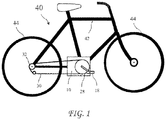
- a bicycle 40 including a mid-motor drive system 10 according to the present invention is shown in FIG. 1 .
- the mid-motor drive system 10 is connected to a bicycle frame 42 and drives a chain (or belt) 30 connected to a drive sprocket 32 driving a bicycle wheel 44.
- a rider may power the bicycle 40 using pedals 18, or using the mid-motor drive system 10, or using the pedals and the mid-motor drive system 10.
- FIG. 2 A first embodiment of a mid-motor drive system 10a is shown in FIG. 2 , a side view of a motor 14 and bottom bracket 38 of the mid-motor drive system 10 is shown in FIG. 3A , and a front view of the motor 14 and bottom bracket 38 is shown in FIG. 3B .
- the motor 14 is preferably a doughnut motor.
- the mid-motor drive system 10a includes a housing 12 containing the motor 14 preferably coaxial with a pedal shaft 16a but rotationally decoupled to the pedal shaft 16a by bearings 17, and pedals 18 attached to the pedal shaft 16a.
- a mid shaft 16b resides parallel with the pedal shaft 16a.
- the mid shaft 16b is coupled by a chain (or belt) 20a connecting a fixed (no clutch) sprocket 15a attached to the pedal shaft 16a, to a sprocket 23a, and the sprocket 23a is connected to the mid shaft 16b through uni-directional bearings (or sprag clutches) 22a.
- the uni-directional bearing 22a couples the chain 20a to the mid shaft 16a when the chain 20a is driven by the pedals 18 to drive the bicycle forward, and decouples the chain 20a from the mid shaft 16b whenever the mid shaft 16b is rotating faster than a rotation produced by the chain 20a.
- the mid shaft 16b is coupled to the motor 14 by a fixed (no clutch) sprocket 15b attached to the motor and a chain (or belt) 20b through uni-directional bearings (or sprag clutches) 22b.
- the uni-directional bearing 22b couples the chain 20b to the mid shaft 16b when the chain 20b is driven by the motor 14 to drive the bicycle forward, and decouple the chain 20b from the mid shaft 16b whenever the mid shaft 16b is rotating faster than a rotation produced by the chain 20b.
- uni-directional bearings 22a and 22b may be replaced by uni-directional bearings connecting the sprocket 15b to the motor 14 and/or connecting the sprocket 15a to the pedal shaft 16a, thereby providing the same functionality as the uni-directional bearings 22a and 22b.
- a sleeve 24 resides over the pedal shaft 16a on bearings to rotate independently of the pedal shaft 16a.
- the mid shaft 16b is further fixedly (i.e., fixed to always rotate together, not through a clutch) coupled to the sleeve 24 by a chain (or belt) 20c to drive the sleeve 24.
- the sleeve 24 carries a sprocket 28 coupled to the drive sprocket 32 by a chain (or belt) 30.
- the sprocket 32 may be a conventional bicycle drive sprocket rotationally fixed to a bicycle wheel, or may be coupled to a transmission 36, for example a multi-speed derailleur, rotationally connected to a bicycle wheel.
- a controller 13 resides inside or outside the housing 12 and is electrically connected to batteries 11 which may reside inside or outside the housing 12, and to the motor 14.
- the controller 13 provides power from the batteries 11 to the motor 14 and the controller 13 may receive data signals from the motor 14, the batteries 11 and/or a pedal torque sensor 27.
- the pedal torque sensor 27 cooperated with the chain 20b to measure the mechanical power generated by the rider to provide a control signal to the controller 13 as an input to the controller 13.
- the pedal torque sensor 27 may measure the torque on the pedal shaft 16a by the rider by sensing tension on the chain 20b between the pedal shaft 16a and mid shaft 16b, or by other means.
- the pedal torque measurements may be used as an input by the controller 13 in determining the amount of motor 14 assistance in the drive system 10.
- the rider may rotate the pedals 18, as on a conventional bicycle, and the bicycle can be powered by the electric motor 14.
- Gear ratio may be changed between the motor sprocket 15b and the mid shaft 16b and between the pedal shaft 16a and the mid shaft 16b and between the mid shaft 16a and the sleeve 24 by replacing sprockets 15a, 15b, 23a, 23b, 23c, and or 26 depending on the specific vehicle application.
- the gear ratio between the motor 14 and mid shaft 16b may be easily adjusted depending on the speed range of the motor and the specific vehicle application.
- FIG. 4 A second embodiment of a mid-motor drive system 10b is shown in FIG. 4 .
- the mid-motor drive system 10b is functionally the same as the mid-motor drive system 10a, but the third mid shaft sprocket 23c and the sleeve sprocket 26, the chain 20c, and the sleeve 24 are placed by moving the sprocket 28 to the mid shaft 16b.
- the mid-motor drive system 10c is similar to the mid-motor drive system 10a, but the motor 14a is preferably a conventional low speed motor.
- the motor 14a has low rotational resistance when not under power and therefore may be rotationally fixed to the mid shaft 16b without producing rotational drag.
- the mid shaft 16b is coupled by the chain (or belt) 20a connecting the fixed (no clutch) sprocket 15a attached to the pedal shaft 16a, to the sprocket 23a, and the sprocket 23a is connected to the mid shaft 16b through uni-directional bearings (or sprag clutches) 22a.
- the mid shaft 16b is coupled to the sleeve 24 through the uni-directional bearings 22c so that the mid shaft 16b can drive the sleeve 24 through the chain 20c, but the sleeve 24 cannot drive the mid shaft 16b through the chain 20c.
- the conventional bicycle sprocket or multispeed derailleur allows for connection via belt or chain to a variety of conventional bicycle transmissions in the rear wheel including, but not limited to, a derailleur, an internal hub, CVT or a traditional in-wheel motor allowing for additional motor output at a different gear ratio.
- the motor and pedals can operate independently of each other without interfering with each other, which means that the drive can be operated as a throttle driven power source with no rider pedal input, a pedal-assist power source that registers rider pedal input and supplies proportional power assist, or as a conventional pedal bike without adding significant amount of drag on the total system.
Landscapes
- Engineering & Computer Science (AREA)
- Chemical & Material Sciences (AREA)
- Combustion & Propulsion (AREA)
- Transportation (AREA)
- Mechanical Engineering (AREA)
- Electric Propulsion And Braking For Vehicles (AREA)
Description
- The present invention relates to electric bicycles and in particular a mid-drive arrangement for electric bicycles.
- In the electric bike market, the "hub" or in-wheel motor has been the dominated configuration. Unfortunately, in in-wheel motor bicycles, there is no way to give a mechanical advantage to the motor using a conventional bicycle transmission. Additionally, when using an in-wheel motor configuration, the rider may input power through the pedals and into a conventional bicycle transmission however, because there is no direct connection between the wheel motor and transmission, it is possible for the rider to choose a gear ratio on the transmission which fails to transfer the rider's power input into the pedals as a useful addition to the bicycle's propulsion. As a result, there is an increasing movement away from an in-wheel motor and there is a need for better alternative motor configurations.
- Mid-motor drive systems have been developed to replace wheel motor based electric drives, but known mid-motor designs use a complicated set of gears to combine the power of the motor with the rider power input through the pedals and then transfers all that power to a conventional bicycle transmission. This design often makes it impossible to operate the motor without rotating the pedals via an independent throttle such throttle driven operation being desirable by many consumers. Thus, a need remains for an improved mid-motor drive system.
- Document
US7108097 , which discloses all the features of the preamble of independent claim 1, shows a mid-motor drive known from the prior art. - The present invention addresses the above and other needs by providing a simplified mid-motor drive system which includes all necessary electronics and allows for throttle-only operation of the motor. The mid-motor drive system includes an arrangement of uni-directional drive connections (i.e., sprag clutches) between the motor and the pedals which allows each to operate independently or in conjunction, and allows simple modifications to gear ratios of packaged drive systems in order to adapt to regulatory requirements of different worldwide territories.
- In accordance with one aspect of the invention, there is provided a mid-drive system allowing for all the power from the motor, as well as all the power from the rider (input through the pedals) to be transferred into a conventional bicycle transmission thus providing a mechanical gearing advantage.
- In accordance with another aspect of the invention, there is provided a mid-drive system package that can easily be integrated into a bicycle frame, with all necessary control electronics, which greatly simplifies the initial manufacturing, wiring and maintenance on an electric bike.
- The above and other aspects, features and advantages of the present invention will be more apparent from the following more particular description thereof, presented in conjunction with the following drawings wherein:
-
FIG. 1 shows a bicycle having a mid drive according to the present invention. -
Fig. 2 shows a first embodiment of a mid-motor drive system according to the present invention. -
FIG. 3A shows a side view of a motor of the mid-motor drive system according to the present invention. -
FIG. 3B shows a front view of the motor of the mid-motor drive system according to the present invention. -
FIG. 4 shows a second embodiment of a mid-motor drive system according to the present invention. -
FIG. 5 shows a not claimed mid-motor drive system. - Corresponding reference characters indicate corresponding components throughout the several views of the drawings.
- The following description is of the best mode presently contemplated for carrying out the invention. This description is not to be taken in a limiting sense, but is made merely for the purpose of describing one or more preferred embodiments of the invention. The scope of the invention should be determined with reference to the claims.
- Where the term "generally" is associated with an element of the invention, it is intended to describe a feature's appearance to the human eye, and not a precise measurement.
- A
bicycle 40 including amid-motor drive system 10 according to the present invention is shown inFIG. 1 . Themid-motor drive system 10 is connected to abicycle frame 42 and drives a chain (or belt) 30 connected to a drive sprocket 32 driving abicycle wheel 44. A rider may power thebicycle 40 usingpedals 18, or using themid-motor drive system 10, or using the pedals and themid-motor drive system 10. - A first embodiment of a
mid-motor drive system 10a is shown inFIG. 2 , a side view of amotor 14 andbottom bracket 38 of themid-motor drive system 10 is shown inFIG. 3A , and a front view of themotor 14 andbottom bracket 38 is shown inFIG. 3B . Themotor 14 is preferably a doughnut motor. Themid-motor drive system 10a includes ahousing 12 containing themotor 14 preferably coaxial with apedal shaft 16a but rotationally decoupled to thepedal shaft 16a bybearings 17, andpedals 18 attached to thepedal shaft 16a. - A
mid shaft 16b resides parallel with thepedal shaft 16a. Themid shaft 16b is coupled by a chain (or belt) 20a connecting a fixed (no clutch)sprocket 15a attached to thepedal shaft 16a, to asprocket 23a, and thesprocket 23a is connected to themid shaft 16b through uni-directional bearings (or sprag clutches) 22a. The uni-directional bearing 22a couples thechain 20a to themid shaft 16a when thechain 20a is driven by thepedals 18 to drive the bicycle forward, and decouples thechain 20a from themid shaft 16b whenever themid shaft 16b is rotating faster than a rotation produced by thechain 20a. - The
mid shaft 16b is coupled to themotor 14 by a fixed (no clutch)sprocket 15b attached to the motor and a chain (or belt) 20b through uni-directional bearings (or sprag clutches) 22b. The uni-directional bearing 22b couples thechain 20b to themid shaft 16b when thechain 20b is driven by themotor 14 to drive the bicycle forward, and decouple thechain 20b from themid shaft 16b whenever themid shaft 16b is rotating faster than a rotation produced by thechain 20b. - Those skilled in the art will recognize that the
uni-directional bearings sprocket 15b to themotor 14 and/or connecting thesprocket 15a to thepedal shaft 16a, thereby providing the same functionality as theuni-directional bearings - A
sleeve 24 resides over thepedal shaft 16a on bearings to rotate independently of thepedal shaft 16a. Themid shaft 16b is further fixedly (i.e., fixed to always rotate together, not through a clutch) coupled to thesleeve 24 by a chain (or belt) 20c to drive thesleeve 24. Thesleeve 24 carries asprocket 28 coupled to thedrive sprocket 32 by a chain (or belt) 30. Thesprocket 32 may be a conventional bicycle drive sprocket rotationally fixed to a bicycle wheel, or may be coupled to atransmission 36, for example a multi-speed derailleur, rotationally connected to a bicycle wheel. - A
controller 13 resides inside or outside thehousing 12 and is electrically connected tobatteries 11 which may reside inside or outside thehousing 12, and to themotor 14. Thecontroller 13 provides power from thebatteries 11 to themotor 14 and thecontroller 13 may receive data signals from themotor 14, thebatteries 11 and/or apedal torque sensor 27. Thepedal torque sensor 27 cooperated with thechain 20b to measure the mechanical power generated by the rider to provide a control signal to thecontroller 13 as an input to thecontroller 13. Thepedal torque sensor 27 may measure the torque on thepedal shaft 16a by the rider by sensing tension on thechain 20b between thepedal shaft 16a andmid shaft 16b, or by other means. The pedal torque measurements may be used as an input by thecontroller 13 in determining the amount ofmotor 14 assistance in thedrive system 10. Alternately, multiple options exist for measuring pedal torque achieve the same result, and a mid drive system using any form of pedal torque measurement is intended to come within the scope of the present invention. A suitable torque sensor is described inUS Patent No. 8,965,610 issued to one of the present inventors. - The rider may rotate the
pedals 18, as on a conventional bicycle, and the bicycle can be powered by theelectric motor 14. Gear ratio may be changed between themotor sprocket 15b and themid shaft 16b and between thepedal shaft 16a and themid shaft 16b and between themid shaft 16a and thesleeve 24 by replacingsprockets motor 14 andmid shaft 16b may be easily adjusted depending on the speed range of the motor and the specific vehicle application. - A second embodiment of a
mid-motor drive system 10b is shown inFIG. 4 . Themid-motor drive system 10b is functionally the same as themid-motor drive system 10a, but the third mid shaft sprocket 23c and thesleeve sprocket 26, thechain 20c, and thesleeve 24 are placed by moving thesprocket 28 to themid shaft 16b. - A not claimed
mid-motor drive system 10c is shown inFIG. 5 . Themid-motor drive system 10c is similar to themid-motor drive system 10a, but themotor 14a is preferably a conventional low speed motor. Themotor 14a has low rotational resistance when not under power and therefore may be rotationally fixed to themid shaft 16b without producing rotational drag. Themid shaft 16b is coupled by the chain (or belt) 20a connecting the fixed (no clutch) sprocket 15a attached to thepedal shaft 16a, to thesprocket 23a, and thesprocket 23a is connected to themid shaft 16b through uni-directional bearings (or sprag clutches) 22a. Themid shaft 16b is coupled to thesleeve 24 through theuni-directional bearings 22c so that themid shaft 16b can drive thesleeve 24 through thechain 20c, but thesleeve 24 cannot drive themid shaft 16b through thechain 20c. - The conventional bicycle sprocket or multispeed derailleur allows for connection via belt or chain to a variety of conventional bicycle transmissions in the rear wheel including, but not limited to, a derailleur, an internal hub, CVT or a traditional in-wheel motor allowing for additional motor output at a different gear ratio.
- Advantageously, the motor and pedals can operate independently of each other without interfering with each other, which means that the drive can be operated as a throttle driven power source with no rider pedal input, a pedal-assist power source that registers rider pedal input and supplies proportional power assist, or as a conventional pedal bike without adding significant amount of drag on the total system.
- While the invention herein disclosed has been described by means of specific embodiments and applications thereof, numerous modifications and variations could be made thereto by those skilled in the art without departing from the scope of the invention set forth in the claims.
Claims (6)
- A mid drive system (10) for an electric bicycle (40), the mid drive system (10) comprising:a pedal shaft (16a) with pedals (18) for a rider;a mid shaft (16b) residing parallel with the pedal shaft (16a);a first pedal shaft sprocket (15a) co-axial with the pedal shaft (16a);a first mid shaft sprocket (23a) co-axial with the mid shaft (16b);a first chain or belt (20a) rotationally couples the first pedal shaft sprocket (15a) to the first mid shaft sprocket (23a);the mid shaft (16b) driven by the pedal shaft (16a) through the first pedal shaft sprocket (15a), the first chain or belt (20a), and the first mid shaft sprocket (23a), and through a first uni-directional bearing (22a), the pedal shaft (16a) rotationally coupled to the mid shaft (16b) by the first uni-directional bearing (22a) when the pedal shaft (16a) drives the mid shaft (16b), and decoupled from the mid shaft (16b) when the pedal shaft (16a) is not driving the mid shaft (16b);an electric motor (14) rotationally coupled to drive the mid shaft (16b);a drive sprocket (28) fixedly rotationally coupled to the mid shaft (16b); anda chain or belt (30) coupling the drive sprocket (28) to a bicycle wheel (44), characterized in thatthe electric motor (14) is resided co-axially with the pedal shaft (16a) and rotationally decoupled to the pedal shaft (16a) by bearings (17);a motor sprocket (15b) resides co-axial with the electric motor (14);a second mid shaft sprocket (23b) reside co-axial with the mid shaft (16b);a second chain or belt (20b) rotationally couples the motor sprocket (15b) to the second mid shaft sprocket (23b); andthe mid shaft (16b) is driven by the electric motor (14) through the motor sprocket (15b), the second chain or belt (20b), and the second mid shaft sprocket (23b), and through a second uni-directional bearing (22b), the electric motor (14) rotationally coupled to the mid shaft (16b) by the second uni-directional bearing (22b) when the electric motor (14) drives the mid shaft (16b), and decoupled from the mid shaft (16b) when the electric motor (14) is not driving the mid shaft (16b).
- The drive system of claim 1, wherein the first mid shaft sprocket (23a) is rotationally coupled to the mid shaft (16b) through the first directional bearing (22a).
- The drive system of any one of the previous claims, wherein the second mid shaft sprocket (23b) is rotationally coupled to the mid shaft (16b) through the second directional bearing (22b).
- The drive system of any one of the previous claims, wherein the chain or belt (30) coupling the drive sprocket (28) to a bicycle wheel (44) comprises:a third mid shaft sprocket (23c) co-axial with the mid shaft (16b);a sleeve (24) co-axial with the pedal shaft (16a) and free to rotate on the pedal shaft (16a);a sleeve sprocket (26) co-axial with the sleeve (24);a third chain or belt (20c) rotationally coupling the third mid shaft sprocket (23c) with the sleeve sprocket (26);a drive sprocket (28) co-axial with the sleeve (24); anda fourth chain or belt (30) rotationally coupling the drive sprocket (28) with the wheel (44) of a bicycle.
- The drive system of any one of claims 1 to 3, wherein the chain or belt (30) coupling the drive sprocket (28) to a bicycle wheel (44) comprises:a drive sprocket (28) co-axial with the mid shaft (16b); anda fourth chain or belt (30) rotationally coupling the drive sprocket (28) with the wheel (44) of a bicycle.
- The drive system of any one of the previous claims, further including a pedal torque sensor (27) configured to measure torque in the first chain or belt (20a), the pedal torque sensor (27) electrically connected to a controller (13) to provide a control signal to the controller (13) and the controller (13) controlling the electric motor (14).
Applications Claiming Priority (2)
| Application Number | Priority Date | Filing Date | Title |
|---|---|---|---|
| US201562218388P | 2015-09-14 | 2015-09-14 | |
| PCT/US2016/051531 WO2017048717A1 (en) | 2015-09-14 | 2016-09-13 | Mid drive assist system for an electric bicycle |
Publications (3)
| Publication Number | Publication Date |
|---|---|
| EP3350070A1 EP3350070A1 (en) | 2018-07-25 |
| EP3350070A4 EP3350070A4 (en) | 2019-06-26 |
| EP3350070B1 true EP3350070B1 (en) | 2021-12-29 |
Family
ID=58236719
Family Applications (1)
| Application Number | Title | Priority Date | Filing Date |
|---|---|---|---|
| EP16847139.9A Active EP3350070B1 (en) | 2015-09-14 | 2016-09-13 | Mid drive assist system for an electric bicycle |
Country Status (4)
| Country | Link |
|---|---|
| US (1) | US10315726B2 (en) |
| EP (1) | EP3350070B1 (en) |
| CN (1) | CN108602545A (en) |
| WO (1) | WO2017048717A1 (en) |
Families Citing this family (11)
| Publication number | Priority date | Publication date | Assignee | Title |
|---|---|---|---|---|
| CN109466678A (en) * | 2017-09-07 | 2019-03-15 | 广州市展辉电子有限公司 | Electric bicycle and its splicing sleeve and vehicle frame |
| WO2020061624A1 (en) * | 2018-09-27 | 2020-04-02 | Cape Bouvard Technologies Pty Ltd | A clutch |
| WO2020223109A1 (en) * | 2019-04-30 | 2020-11-05 | Blount, Inc. | Electric-powered gas engine replacement |
| GB2580446B (en) * | 2019-06-05 | 2020-12-16 | Ebike Systems Ltd | Electrically-assisted pedal cycles |
| IT201900019844A1 (en) * | 2019-10-28 | 2021-04-28 | Texa Dynamics S R L | "Propulsion unit for electric assisted bicycle" |
| US12005936B2 (en) * | 2020-03-13 | 2024-06-11 | Mendocino Railway | Rail vehicle with human and/or electric power |
| NL2028537B1 (en) * | 2021-06-24 | 2023-01-02 | Roetz Bikes B V | Mid-drive module for a pedal-powered vehicle |
| GB2610865B (en) * | 2021-09-20 | 2023-08-23 | Vo Vehicles Ltd | A compact ground vehicle with electric propulsion |
| JP7778581B2 (en) * | 2022-01-31 | 2025-12-02 | 株式会社シマノ | Drive unit for human-powered vehicles |
| JP7778580B2 (en) * | 2022-01-31 | 2025-12-02 | 株式会社シマノ | Drive unit for human-powered vehicles |
| JP2025542031A (en) * | 2022-12-19 | 2025-12-24 | ゲイツ コーポレイション | Electric bicycle mid-drive motor with belt-driven transmission |
Citations (1)
| Publication number | Priority date | Publication date | Assignee | Title |
|---|---|---|---|---|
| US7108097B1 (en) * | 2004-04-06 | 2006-09-19 | Brent Cecil Bolton | Power assisted recumbent bicycle and power unit |
Family Cites Families (17)
| Publication number | Priority date | Publication date | Assignee | Title |
|---|---|---|---|---|
| US3598195A (en) * | 1969-04-23 | 1971-08-10 | Stelber Ind Inc | Electric tricycle |
| US4280581A (en) * | 1978-05-12 | 1981-07-28 | Rudwick Lawrence A | Motor and pedal driven bicycles |
| JPH08290795A (en) * | 1995-02-21 | 1996-11-05 | Seiko Epson Corp | Auxiliary power unit |
| JP3939813B2 (en) * | 1996-08-02 | 2007-07-04 | ヤマハ発動機株式会社 | Power assisted bicycle |
| TW371646B (en) * | 1996-09-26 | 1999-10-11 | Mistubishi Heavy Ind Ltd | Driving unit for an electric motor driven bicycle |
| CN2324048Y (en) * | 1998-03-13 | 1999-06-16 | 蔡高德 | fully automatic power assist bicycle |
| JP2000118477A (en) * | 1998-10-12 | 2000-04-25 | Sony Corp | Bicycle with assist function |
| US6964313B2 (en) * | 2003-01-23 | 2005-11-15 | Biketoo, Incorporated | Personal transport vehicle, such as a bicycle |
| US20060064223A1 (en) * | 2004-09-20 | 2006-03-23 | Darrell Voss | Vehicle systems and method |
| US7261175B1 (en) * | 2004-09-24 | 2007-08-28 | Todd Fahrner | Power assisted bicycle |
| CN201169370Y (en) * | 2008-01-08 | 2008-12-24 | 戴荣治 | Power saving device for electric and pedal bicycle |
| DE102010009649B4 (en) * | 2010-03-02 | 2017-01-05 | Karlheinz Nicolai | Bicycle with electric auxiliary drive |
| JP2012051446A (en) * | 2010-08-31 | 2012-03-15 | Honda Motor Co Ltd | Bicycle with auxiliary power unit |
| CN103732487A (en) | 2011-05-23 | 2014-04-16 | 托马斯·博伊勒 | Pedal assist sensor |
| JP5470358B2 (en) * | 2011-11-29 | 2014-04-16 | 本田技研工業株式会社 | Magnetostrictive torque sensor, electrically assisted bicycle and electric power steering apparatus equipped with this magnetostrictive torque sensor |
| DE102012210400A1 (en) * | 2012-06-20 | 2013-12-24 | Robert Bosch Gmbh | Mounting unit for drive part of bicycle, has fastening part fastening at lower tube and seat tube of bicycle using screw and comprising clamping part that is firmly clamped to pipe of frame, and adapter receiving drive part |
| WO2014027386A1 (en) * | 2012-08-17 | 2014-02-20 | パナソニック株式会社 | Power-assisted bicycle |
-
2016
- 2016-09-13 US US15/264,135 patent/US10315726B2/en active Active
- 2016-09-13 EP EP16847139.9A patent/EP3350070B1/en active Active
- 2016-09-13 CN CN201680066824.6A patent/CN108602545A/en active Pending
- 2016-09-13 WO PCT/US2016/051531 patent/WO2017048717A1/en not_active Ceased
Patent Citations (1)
| Publication number | Priority date | Publication date | Assignee | Title |
|---|---|---|---|---|
| US7108097B1 (en) * | 2004-04-06 | 2006-09-19 | Brent Cecil Bolton | Power assisted recumbent bicycle and power unit |
Also Published As
| Publication number | Publication date |
|---|---|
| US20170073039A1 (en) | 2017-03-16 |
| US10315726B2 (en) | 2019-06-11 |
| CN108602545A (en) | 2018-09-28 |
| EP3350070A4 (en) | 2019-06-26 |
| WO2017048717A1 (en) | 2017-03-23 |
| EP3350070A1 (en) | 2018-07-25 |
Similar Documents
| Publication | Publication Date | Title |
|---|---|---|
| US10315726B2 (en) | Mid drive system for an electric bicycle | |
| US11130548B2 (en) | Human-powered vehicle control device | |
| US12195137B2 (en) | Power transmission unit for electric bicycles, and electric bicycle | |
| US9221516B1 (en) | Hub motor structure | |
| US11124267B2 (en) | Human-powered vehicle control device | |
| CN111247064A (en) | Powertrain | |
| US20170137086A1 (en) | Bicycle drive unit | |
| US8651993B1 (en) | Bicycle drive unit | |
| US20170219066A1 (en) | Bicycle driving device | |
| CN107000808A (en) | Bicycle drive unit | |
| US10137959B2 (en) | Electric bicycle drive assembly with torque detection | |
| US11167818B2 (en) | Human-powered vehicle control device | |
| JP7863595B2 (en) | Transmission system for human-powered vehicles | |
| CN103171732B (en) | Crank gear for bicycle | |
| KR101516075B1 (en) | Eletricity bike control system and method for control the same | |
| CN107000809A (en) | Bicycle drive unit | |
| JPWO2019103022A1 (en) | Electric assisted bicycle drive unit and electrically assisted bicycle | |
| DK181416B1 (en) | Electric Pedal Assist Bicycle Powertrain and a Bicycle with the Powertrain | |
| CN107406117A (en) | Electric bicycle | |
| JP2014019181A (en) | Driving unit for bicycle | |
| US10604210B2 (en) | Human-powered vehicle control device | |
| US20260042506A1 (en) | Electrical pedal assist bicycle powertrain | |
| CN108025797B (en) | Torque sensors for pedal-driven vehicles and equipment | |
| JP7296298B2 (en) | Control device for man-powered vehicles | |
| TW202400475A (en) | control device |
Legal Events
| Date | Code | Title | Description |
|---|---|---|---|
| STAA | Information on the status of an ep patent application or granted ep patent |
Free format text: STATUS: THE INTERNATIONAL PUBLICATION HAS BEEN MADE |
|
| PUAI | Public reference made under article 153(3) epc to a published international application that has entered the european phase |
Free format text: ORIGINAL CODE: 0009012 |
|
| STAA | Information on the status of an ep patent application or granted ep patent |
Free format text: STATUS: REQUEST FOR EXAMINATION WAS MADE |
|
| 17P | Request for examination filed |
Effective date: 20180322 |
|
| AK | Designated contracting states |
Kind code of ref document: A1 Designated state(s): AL AT BE BG CH CY CZ DE DK EE ES FI FR GB GR HR HU IE IS IT LI LT LU LV MC MK MT NL NO PL PT RO RS SE SI SK SM TR |
|
| AX | Request for extension of the european patent |
Extension state: BA ME |
|
| DAV | Request for validation of the european patent (deleted) | ||
| DAX | Request for extension of the european patent (deleted) | ||
| A4 | Supplementary search report drawn up and despatched |
Effective date: 20190524 |
|
| RIC1 | Information provided on ipc code assigned before grant |
Ipc: B62M 6/55 20100101AFI20190520BHEP Ipc: B62K 11/00 20060101ALI20190520BHEP Ipc: B62M 9/02 20060101ALI20190520BHEP |
|
| STAA | Information on the status of an ep patent application or granted ep patent |
Free format text: STATUS: EXAMINATION IS IN PROGRESS |
|
| 17Q | First examination report despatched |
Effective date: 20200409 |
|
| GRAP | Despatch of communication of intention to grant a patent |
Free format text: ORIGINAL CODE: EPIDOSNIGR1 |
|
| STAA | Information on the status of an ep patent application or granted ep patent |
Free format text: STATUS: GRANT OF PATENT IS INTENDED |
|
| INTG | Intention to grant announced |
Effective date: 20210812 |
|
| GRAS | Grant fee paid |
Free format text: ORIGINAL CODE: EPIDOSNIGR3 |
|
| GRAA | (expected) grant |
Free format text: ORIGINAL CODE: 0009210 |
|
| STAA | Information on the status of an ep patent application or granted ep patent |
Free format text: STATUS: THE PATENT HAS BEEN GRANTED |
|
| AK | Designated contracting states |
Kind code of ref document: B1 Designated state(s): AL AT BE BG CH CY CZ DE DK EE ES FI FR GB GR HR HU IE IS IT LI LT LU LV MC MK MT NL NO PL PT RO RS SE SI SK SM TR |
|
| REG | Reference to a national code |
Ref country code: GB Ref legal event code: FG4D |
|
| REG | Reference to a national code |
Ref country code: CH Ref legal event code: EP |
|
| REG | Reference to a national code |
Ref country code: AT Ref legal event code: REF Ref document number: 1458497 Country of ref document: AT Kind code of ref document: T Effective date: 20220115 |
|
| REG | Reference to a national code |
Ref country code: IE Ref legal event code: FG4D |
|
| REG | Reference to a national code |
Ref country code: DE Ref legal event code: R096 Ref document number: 602016067920 Country of ref document: DE |
|
| REG | Reference to a national code |
Ref country code: LT Ref legal event code: MG9D |
|
| PG25 | Lapsed in a contracting state [announced via postgrant information from national office to epo] |
Ref country code: RS Free format text: LAPSE BECAUSE OF FAILURE TO SUBMIT A TRANSLATION OF THE DESCRIPTION OR TO PAY THE FEE WITHIN THE PRESCRIBED TIME-LIMIT Effective date: 20211229 Ref country code: LT Free format text: LAPSE BECAUSE OF FAILURE TO SUBMIT A TRANSLATION OF THE DESCRIPTION OR TO PAY THE FEE WITHIN THE PRESCRIBED TIME-LIMIT Effective date: 20211229 Ref country code: FI Free format text: LAPSE BECAUSE OF FAILURE TO SUBMIT A TRANSLATION OF THE DESCRIPTION OR TO PAY THE FEE WITHIN THE PRESCRIBED TIME-LIMIT Effective date: 20211229 Ref country code: BG Free format text: LAPSE BECAUSE OF FAILURE TO SUBMIT A TRANSLATION OF THE DESCRIPTION OR TO PAY THE FEE WITHIN THE PRESCRIBED TIME-LIMIT Effective date: 20220329 |
|
| REG | Reference to a national code |
Ref country code: NL Ref legal event code: MP Effective date: 20211229 |
|
| REG | Reference to a national code |
Ref country code: AT Ref legal event code: MK05 Ref document number: 1458497 Country of ref document: AT Kind code of ref document: T Effective date: 20211229 |
|
| PG25 | Lapsed in a contracting state [announced via postgrant information from national office to epo] |
Ref country code: SE Free format text: LAPSE BECAUSE OF FAILURE TO SUBMIT A TRANSLATION OF THE DESCRIPTION OR TO PAY THE FEE WITHIN THE PRESCRIBED TIME-LIMIT Effective date: 20211229 Ref country code: NO Free format text: LAPSE BECAUSE OF FAILURE TO SUBMIT A TRANSLATION OF THE DESCRIPTION OR TO PAY THE FEE WITHIN THE PRESCRIBED TIME-LIMIT Effective date: 20220329 Ref country code: LV Free format text: LAPSE BECAUSE OF FAILURE TO SUBMIT A TRANSLATION OF THE DESCRIPTION OR TO PAY THE FEE WITHIN THE PRESCRIBED TIME-LIMIT Effective date: 20211229 Ref country code: HR Free format text: LAPSE BECAUSE OF FAILURE TO SUBMIT A TRANSLATION OF THE DESCRIPTION OR TO PAY THE FEE WITHIN THE PRESCRIBED TIME-LIMIT Effective date: 20211229 Ref country code: GR Free format text: LAPSE BECAUSE OF FAILURE TO SUBMIT A TRANSLATION OF THE DESCRIPTION OR TO PAY THE FEE WITHIN THE PRESCRIBED TIME-LIMIT Effective date: 20220330 |
|
| PG25 | Lapsed in a contracting state [announced via postgrant information from national office to epo] |
Ref country code: NL Free format text: LAPSE BECAUSE OF FAILURE TO SUBMIT A TRANSLATION OF THE DESCRIPTION OR TO PAY THE FEE WITHIN THE PRESCRIBED TIME-LIMIT Effective date: 20211229 |
|
| PG25 | Lapsed in a contracting state [announced via postgrant information from national office to epo] |
Ref country code: SM Free format text: LAPSE BECAUSE OF FAILURE TO SUBMIT A TRANSLATION OF THE DESCRIPTION OR TO PAY THE FEE WITHIN THE PRESCRIBED TIME-LIMIT Effective date: 20211229 Ref country code: SK Free format text: LAPSE BECAUSE OF FAILURE TO SUBMIT A TRANSLATION OF THE DESCRIPTION OR TO PAY THE FEE WITHIN THE PRESCRIBED TIME-LIMIT Effective date: 20211229 Ref country code: RO Free format text: LAPSE BECAUSE OF FAILURE TO SUBMIT A TRANSLATION OF THE DESCRIPTION OR TO PAY THE FEE WITHIN THE PRESCRIBED TIME-LIMIT Effective date: 20211229 Ref country code: PT Free format text: LAPSE BECAUSE OF FAILURE TO SUBMIT A TRANSLATION OF THE DESCRIPTION OR TO PAY THE FEE WITHIN THE PRESCRIBED TIME-LIMIT Effective date: 20220429 Ref country code: ES Free format text: LAPSE BECAUSE OF FAILURE TO SUBMIT A TRANSLATION OF THE DESCRIPTION OR TO PAY THE FEE WITHIN THE PRESCRIBED TIME-LIMIT Effective date: 20211229 Ref country code: EE Free format text: LAPSE BECAUSE OF FAILURE TO SUBMIT A TRANSLATION OF THE DESCRIPTION OR TO PAY THE FEE WITHIN THE PRESCRIBED TIME-LIMIT Effective date: 20211229 Ref country code: CZ Free format text: LAPSE BECAUSE OF FAILURE TO SUBMIT A TRANSLATION OF THE DESCRIPTION OR TO PAY THE FEE WITHIN THE PRESCRIBED TIME-LIMIT Effective date: 20211229 |
|
| PG25 | Lapsed in a contracting state [announced via postgrant information from national office to epo] |
Ref country code: PL Free format text: LAPSE BECAUSE OF FAILURE TO SUBMIT A TRANSLATION OF THE DESCRIPTION OR TO PAY THE FEE WITHIN THE PRESCRIBED TIME-LIMIT Effective date: 20211229 Ref country code: AT Free format text: LAPSE BECAUSE OF FAILURE TO SUBMIT A TRANSLATION OF THE DESCRIPTION OR TO PAY THE FEE WITHIN THE PRESCRIBED TIME-LIMIT Effective date: 20211229 |
|
| PG25 | Lapsed in a contracting state [announced via postgrant information from national office to epo] |
Ref country code: IS Free format text: LAPSE BECAUSE OF FAILURE TO SUBMIT A TRANSLATION OF THE DESCRIPTION OR TO PAY THE FEE WITHIN THE PRESCRIBED TIME-LIMIT Effective date: 20220429 |
|
| REG | Reference to a national code |
Ref country code: DE Ref legal event code: R097 Ref document number: 602016067920 Country of ref document: DE |
|
| PG25 | Lapsed in a contracting state [announced via postgrant information from national office to epo] |
Ref country code: DK Free format text: LAPSE BECAUSE OF FAILURE TO SUBMIT A TRANSLATION OF THE DESCRIPTION OR TO PAY THE FEE WITHIN THE PRESCRIBED TIME-LIMIT Effective date: 20211229 Ref country code: AL Free format text: LAPSE BECAUSE OF FAILURE TO SUBMIT A TRANSLATION OF THE DESCRIPTION OR TO PAY THE FEE WITHIN THE PRESCRIBED TIME-LIMIT Effective date: 20211229 |
|
| PLBE | No opposition filed within time limit |
Free format text: ORIGINAL CODE: 0009261 |
|
| STAA | Information on the status of an ep patent application or granted ep patent |
Free format text: STATUS: NO OPPOSITION FILED WITHIN TIME LIMIT |
|
| 26N | No opposition filed |
Effective date: 20220930 |
|
| PG25 | Lapsed in a contracting state [announced via postgrant information from national office to epo] |
Ref country code: SI Free format text: LAPSE BECAUSE OF FAILURE TO SUBMIT A TRANSLATION OF THE DESCRIPTION OR TO PAY THE FEE WITHIN THE PRESCRIBED TIME-LIMIT Effective date: 20211229 |
|
| PG25 | Lapsed in a contracting state [announced via postgrant information from national office to epo] |
Ref country code: MC Free format text: LAPSE BECAUSE OF FAILURE TO SUBMIT A TRANSLATION OF THE DESCRIPTION OR TO PAY THE FEE WITHIN THE PRESCRIBED TIME-LIMIT Effective date: 20211229 |
|
| REG | Reference to a national code |
Ref country code: CH Ref legal event code: PL |
|
| REG | Reference to a national code |
Ref country code: BE Ref legal event code: MM Effective date: 20220930 |
|
| PG25 | Lapsed in a contracting state [announced via postgrant information from national office to epo] |
Ref country code: IT Free format text: LAPSE BECAUSE OF FAILURE TO SUBMIT A TRANSLATION OF THE DESCRIPTION OR TO PAY THE FEE WITHIN THE PRESCRIBED TIME-LIMIT Effective date: 20211229 |
|
| PG25 | Lapsed in a contracting state [announced via postgrant information from national office to epo] |
Ref country code: LU Free format text: LAPSE BECAUSE OF NON-PAYMENT OF DUE FEES Effective date: 20220913 |
|
| PG25 | Lapsed in a contracting state [announced via postgrant information from national office to epo] |
Ref country code: LI Free format text: LAPSE BECAUSE OF NON-PAYMENT OF DUE FEES Effective date: 20220930 Ref country code: IE Free format text: LAPSE BECAUSE OF NON-PAYMENT OF DUE FEES Effective date: 20220913 Ref country code: CH Free format text: LAPSE BECAUSE OF NON-PAYMENT OF DUE FEES Effective date: 20220930 |
|
| PG25 | Lapsed in a contracting state [announced via postgrant information from national office to epo] |
Ref country code: BE Free format text: LAPSE BECAUSE OF NON-PAYMENT OF DUE FEES Effective date: 20220930 |
|
| PG25 | Lapsed in a contracting state [announced via postgrant information from national office to epo] |
Ref country code: HU Free format text: LAPSE BECAUSE OF FAILURE TO SUBMIT A TRANSLATION OF THE DESCRIPTION OR TO PAY THE FEE WITHIN THE PRESCRIBED TIME-LIMIT; INVALID AB INITIO Effective date: 20160913 |
|
| PG25 | Lapsed in a contracting state [announced via postgrant information from national office to epo] |
Ref country code: CY Free format text: LAPSE BECAUSE OF FAILURE TO SUBMIT A TRANSLATION OF THE DESCRIPTION OR TO PAY THE FEE WITHIN THE PRESCRIBED TIME-LIMIT Effective date: 20211229 |
|
| PG25 | Lapsed in a contracting state [announced via postgrant information from national office to epo] |
Ref country code: MK Free format text: LAPSE BECAUSE OF FAILURE TO SUBMIT A TRANSLATION OF THE DESCRIPTION OR TO PAY THE FEE WITHIN THE PRESCRIBED TIME-LIMIT Effective date: 20211229 |
|
| PG25 | Lapsed in a contracting state [announced via postgrant information from national office to epo] |
Ref country code: MT Free format text: LAPSE BECAUSE OF FAILURE TO SUBMIT A TRANSLATION OF THE DESCRIPTION OR TO PAY THE FEE WITHIN THE PRESCRIBED TIME-LIMIT Effective date: 20211229 |
|
| PGFP | Annual fee paid to national office [announced via postgrant information from national office to epo] |
Ref country code: DE Payment date: 20250917 Year of fee payment: 10 |
|
| PGFP | Annual fee paid to national office [announced via postgrant information from national office to epo] |
Ref country code: GB Payment date: 20250916 Year of fee payment: 10 |
|
| PGFP | Annual fee paid to national office [announced via postgrant information from national office to epo] |
Ref country code: FR Payment date: 20250916 Year of fee payment: 10 |
|
| PG25 | Lapsed in a contracting state [announced via postgrant information from national office to epo] |
Ref country code: TR Free format text: LAPSE BECAUSE OF FAILURE TO SUBMIT A TRANSLATION OF THE DESCRIPTION OR TO PAY THE FEE WITHIN THE PRESCRIBED TIME-LIMIT Effective date: 20211229 |