EP3349975B1 - Dispositif de chauffage d'une zone donnée d'une pièce - Google Patents
Dispositif de chauffage d'une zone donnée d'une pièce Download PDFInfo
- Publication number
- EP3349975B1 EP3349975B1 EP16775305.2A EP16775305A EP3349975B1 EP 3349975 B1 EP3349975 B1 EP 3349975B1 EP 16775305 A EP16775305 A EP 16775305A EP 3349975 B1 EP3349975 B1 EP 3349975B1
- Authority
- EP
- European Patent Office
- Prior art keywords
- skirt
- annular space
- rigid
- duct
- annular
- Prior art date
- Legal status (The legal status is an assumption and is not a legal conclusion. Google has not performed a legal analysis and makes no representation as to the accuracy of the status listed.)
- Active
Links
Images
Classifications
-
- B—PERFORMING OPERATIONS; TRANSPORTING
- B29—WORKING OF PLASTICS; WORKING OF SUBSTANCES IN A PLASTIC STATE IN GENERAL
- B29C—SHAPING OR JOINING OF PLASTICS; SHAPING OF MATERIAL IN A PLASTIC STATE, NOT OTHERWISE PROVIDED FOR; AFTER-TREATMENT OF THE SHAPED PRODUCTS, e.g. REPAIRING
- B29C73/00—Repairing of articles made from plastics or substances in a plastic state, e.g. of articles shaped or produced by using techniques covered by this subclass or subclass B29D
- B29C73/24—Apparatus or accessories not otherwise provided for
- B29C73/30—Apparatus or accessories not otherwise provided for for local pressing or local heating
- B29C73/34—Apparatus or accessories not otherwise provided for for local pressing or local heating for local heating
-
- B—PERFORMING OPERATIONS; TRANSPORTING
- B29—WORKING OF PLASTICS; WORKING OF SUBSTANCES IN A PLASTIC STATE IN GENERAL
- B29L—INDEXING SCHEME ASSOCIATED WITH SUBCLASS B29C, RELATING TO PARTICULAR ARTICLES
- B29L2031/00—Other particular articles
- B29L2031/748—Machines or parts thereof not otherwise provided for
- B29L2031/7504—Turbines
Definitions
- the invention relates to a device for heating a given area of a room, such as a surface of a turbomachine casing.
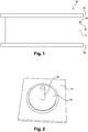
- a turbomachine comprises an intermediate casing 10 arranged between a low pressure compressor and a high pressure compressor.
- a casing 10 comprises a substantially cylindrical wall 11 extending between an upstream flange 12 and a downstream flange 14, these flanges 12, 14 serving to fix the intermediate casing on stator parts of the turbomachine ( Figures 1 and 2 ).
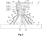
- the outer surface of the wall 11 of the housing is used in particular for the attachment of equipment, a thermal protection envelope or fluid passage conduits.
- a thermal protection envelope or fluid passage conduits.
- threaded rods 16 carried by a base plate 18 of carbon composite, the latter being fixed on the outer surface of the cylindrical wall 11 of the housing 10 by means of a thermosetting glue.
- the housing 10 must be placed in an oven for a predetermined period of time which may be several hours, which interrupts all subsequent manufacturing steps requiring the housing.
- the displacement of an intermediate housing may be difficult to achieve in the case where it has a large diameter, of the order of one to two meters.
- some equipment can not be placed in an oven because of a size too large.
- the document US2005 / 0056632 relates to a polymerization system of a composite.
- the invention aims in particular to provide a simple, effective and economical solution to this problem.
- a device for confining a given zone of a part comprising a first rigid skirt open at a first end which is adapted to be applied around said zone.
- given piece and a second flexible and elastic skirt open at the same first end as the first skirt and intended to come apply to the workpiece, the second skirt remotely surrounding the first rigid skirt so as to form an annular space which is connected to means of depression of the annular space when the first ends of the first skirt and the second skirt are applied on the piece.
- the invention makes it possible to apply a confinement device around the workpiece to thereby locally heat the workpiece at the place where it is desired to carry out a heating operation to perform, for example, a polymerization operation. a glue. This avoids heating the entire room.
- the first skirt makes it possible to achieve confinement of the part at the level of the zone surrounded by its first end applied to the part.
- the first skirt and the second skirt together define an annular space which is connected to means for depressurizing the annular space, thus allowing the device to be held on the part.
- first rigid skirt makes it possible to maintain a non-deformable fixed volume inside the latter, allowing mounting inside the first skirt of a fastening member on the part.
- second flexible and elastic skirt makes it possible to guarantee the maintenance of the heating device on the part to be heated, in particular when the device does not rest on the part to be heated.
- the device of the invention allows in case of breakage of a fastener on the housing to repair faster, without performing a complex disassembly of the engine.
- a repair under the wing could also be considered, thus avoiding a very expensive engine removal.
- the term "annular" used to define the separation space of the first and second skirts should be interpreted as being a space that does not necessarily have a circular shape but is a space extending between the first and second skirts over 360 °.
- the first rigid skirt is made of a resistive material and is connected to power supply means.
- the material is for example thermosetting.
- the first skirt is covered with a layer of thermal insulation on its side facing the second skirt, which allows to confine the heat inside the first skirt.
- the insulating layer may be of thermoset material or of refractory material.
- the vacuum means comprise a venturi effect duct comprising a suction orifice fluidly connected to said annular space, so as to be able to apply a vacuum inside said annular separation space between the first skirt and the second skirt.
- a locking valve can be arranged at the junction between the duct and the inlet of the annular space in order to guarantee that the device is held on the part while no longer requiring the operation of the means for depressurizing the annular space. after a depression has been established in the annular space.
- Said first annular end of the first skirt may comprise sealing means such as a seal.
- the device preferably comprises means for measuring the temperature inside the first skirt, such as a thermocouple probe, in order to control in real time the temperature inside the first skirt.
- figure 3 represents a confinement device according to the invention comprising a first enclosure or skirt 20 comprising a first end 22 applied on the outer surface of the cylindrical wall 11 of the housing 10 described with reference to FIG. figure 1 .
- the first skirt 20 is made of a rigid material so that it defines internally a non-deformable volume within which a base 18 can be received, the base 18 being applied to the housing 10 and carrying a rod threaded 16 extending substantially perpendicular to the outer surface 11 of the casing 10.
- the first rigid skirt 20 is surrounded externally by a second skirt 24 flexible and elastic. This second skirt 24 remotely surrounds the first skirt 20 so as to define an annular space 26 between the first skirt 20 and the second skirt 24.
- the first skirt 20 comprises an opening at its first annular end 22 which carries sealing means such as an annular seal 23 so as to provide a sealing support between this first end 22 and the outer surface 11 of the housing 10 on which the first end 22 of the first skirt 20 is applied.
- the first skirt 20 comprises a frustoconical wall 28 with a section flaring towards the first end of the skirt 20 and is connected at its second end 30 opposite to a second substantially flat wall 32.
- the first skirt 20 forms with the zone of the part surrounded by the first skirt 20, a closed enclosure.
- first skirt 20 is here dictated by the shape of the base 18 and the rod 16 and the position in which it is desired to fix this base on the housing 10.
- first skirt 20 can take any form suitable for engagement around a given area to be heated in a room.
- the second skirt 24 also comprises an opening at a first annular end 34 bearing on the outer surface of the cylindrical wall 11 of the housing 10.
- This second skirt 24 has a generally frustoconical shape flaring towards the first end 34 and has one or more convex bellows or bulges 36 to facilitate the elastic deformation of its wall.
- the second skirt 24 comprises a second end 38 opposite to the first end 34 and integral with a duct 40.
- the device comprises means for depression of the annular space.
- these means comprise a vacuum pump comprising an X-axis venturi duct 40 comprising at an upstream end a small-diameter air inlet orifice 42 and at an downstream end an air outlet orifice 44 of larger diameter.
- the duct 40 comprises a lateral orifice 46 for air suction communicating on one side with the interior of the duct 40 and on the other side with the annular space 26 for separating the first skirt 20 and the second skirt. 24.
- the plane wall 32 of the first skirt 20 is connected to a support arm 48 traversing with clearance the suction orifice 46 and engaged in a fixed support 50 of the duct 40.
- the frustoconical wall 28 of the first skirt 20 is covered a thermal insulation layer 52 on its side facing the second skirt 24, which allows to confine the heat of the heat radiation emitted by the first skirt 20 inside thereof.
- the insulating layer 52 may be in thermoset or refractory material.
- the first skirt 20 and the support arm 48 are made of a resistive material and are connected to electrical supply means 54.
- the resistive material is for example made of a thermosetting material.
- the second end 38 of the second skirt 24 is fixed in the support 50 which surrounds the air suction port 46.
- the sending of a pressurized air flow 55 through the inlet orifice 42 induces a suction of the air from the annular space 26 which exits through the outlet orifice 44 of the duct 40.
- the reduction of the pressure in the annular space 26 thus allows a sealing application of the first skirt 20 and the second skirt 24 on the casing 10.
- the device also comprises means for measuring the temperature inside the first skirt. These means comprise for example a thermocouple probe 56 arranged inside the first skirt 20 and externally connected to temperature processing and display means 58.
- the device may also comprise a non-return valve 60 arranged, for example, at the suction port so as to maintain the vacuum in the annular space 26 when it is established by the vacuum pump.
Landscapes
- Engineering & Computer Science (AREA)
- Mechanical Engineering (AREA)
- Thermal Insulation (AREA)
- Structures Of Non-Positive Displacement Pumps (AREA)
- Furnace Housings, Linings, Walls, And Ceilings (AREA)
Description
- L'invention concerne un dispositif de chauffage d'une zone donnée d'une pièce, telle qu'une surface d'un carter de turbomachine.
- Classiquement, une turbomachine comprend un carter intermédiaire 10 agencé entre un compresseur basse pression et un compresseur haute pression. Un tel carter 10 comprend une paroi sensiblement cylindrique 11 s'étendant entre une bride amont 12 et une bride aval 14, ces brides 12, 14 servant à la fixation du carter intermédiaire sur des parties statoriques de la turbomachine (
figures 1 et 2 ). - La surface externe de la paroi 11 du carter sert notamment à l'accrochage d'équipements, d'une enveloppe de protection thermique ou encore de conduits de passage de fluide. En particulier, pour fixer l'enveloppe de protection thermique, il est connu d'utiliser des tiges filetées 16 portées par une embase 18 en composite carbone, cette dernière étant fixée sur la surface externe de la paroi cylindrique 11 du carter 10 au moyen d'une colle thermodurcissable. Pour cela, le carter 10 doit être placé dans un four durant une période déterminée au préalable qui peut être de plusieurs heures, ce qui interrompt toutes les étapes de fabrication subséquentes nécessitant le carter. De plus, le déplacement d'un carter intermédiaire peut s'avérer délicat à réaliser dans le cas où celui-ci a un important diamètre, de l'ordre de un à deux mètres. De plus, certains équipements ne peuvent pas être placés dans un four du fait d'une taille trop importante.
- Le document
US2005/0056632 concerne un système de polymérisation d'un composite. - L'invention a notamment pour but d'apporter une solution simple, efficace et économique à ce problème.
- A cet effet, elle propose un dispositif de confinement d'une zone donnée d'une pièce comprenant une première jupe rigide ouverte à une première extrémité qui est apte à venir s'appliquer autour de ladite zone donnée de la pièce et une seconde jupe souple et élastique ouverte à une même première extrémité que la première jupe et destinée à venir s'appliquer sur la pièce, la seconde jupe entourant à distance la première jupe rigide de manière à former un espace annulaire qui est relié à des moyens de mise en dépression de l'espace annulaire lorsque les premières extrémités de la première jupe et de la seconde jupe sont appliquées sur la pièce.
- A la différence de la technique antérieure, l'invention permet d'appliquer un dispositif de confinement autour de la pièce pour ainsi venir chauffer localement la pièce à l'endroit où l'on souhaite effectuer un chauffage pour effectuer par exemple une opération de polymérisation d'une colle. On évite ainsi le chauffage de l'intégralité de la pièce.
- La première jupe permet de réaliser un confinement de la pièce au niveau de la zone entourée par sa première extrémité appliquée sur la pièce. La première jupe et la seconde jupe définissent ensemble un espace annulaire qui est relié à des moyens de mise en dépression de l'espace annulaire, permettant ainsi un maintien du dispositif sur la pièce.
- L'utilisation d'une première jupe rigide permet de maintenir un volume fixe non déformable à l'intérieur de celle-ci, autorisant le montage à l'intérieur de la première jupe d'un organe d'accrochage sur la pièce. L'utilisation d'une seconde jupe souple et élastique permet de garantir le maintien du dispositif de chauffage sur la pièce à chauffer, en particulier lorsque le dispositif ne repose pas sur la pièce à chauffer.
- Le dispositif selon l'invention permet en cas de casse d'un organe de fixation sur le carter de le réparer plus rapidement, sans effectuer un démontage complexe du moteur. Une réparation sous l'aile pourrait aussi être envisagée, évitant ainsi une dépose du moteur très coûteuse.
- On notera que dans la demande, le terme « annulaire » utilisé pour définir l'espace de séparation des première et seconde jupes doit s'interpréter comme étant un espace qui n'a pas nécessairement une forme circulaire mais qui est un espace s'étendant entre les première et seconde jupes sur 360°.
- Selon une autre caractéristique de l'invention, la première jupe rigide est réalisée dans un matériau résistif et est reliée à des moyens d'alimentation électrique. Le matériau est par exemple thermodurcissable.
- Selon encore une autre caractéristique de l'invention, la première jupe est recouverte d'une couche d'isolant thermique sur sa face orientée vers la seconde jupe, ce qui permet de confiner la chaleur à l'intérieur de la première jupe. La couche isolante peut être en matériau thermodur ou en matériau réfractaire.
- Dans une réalisation de l'invention, les moyens de mise en dépression comprennent un conduit à effet venturi comportant un orifice d'aspiration relié fluidiquement audit espace annulaire, de manière à pouvoir appliquer une dépression à l'intérieur dudit espace annulaire de séparation entre la première jupe et la seconde jupe.
- Un clapet de blocage peut être agencé à la jonction entre le conduit et l'entrée de l'espace annulaire afin de garantir un maintien du dispositif sur la pièce tout en ne nécessitant plus le fonctionnement des moyens de mise en dépression de l'espace annulaire après qu'une dépression a été établie dans l'espace annulaire.
- Ladite première extrémité annulaire de la première jupe peut comprendre des moyens d'étanchéité tels qu'un joint.
- Le dispositif comprend, de préférence, des moyens de mesure de la température à l'intérieur de la première jupe, tels qu'une sonde à thermocouple, afin de contrôler en temps réel la température à l'intérieur de la première jupe.
- L'invention sera mieux comprise et d'autres détails, caractéristiques et avantages de l'invention apparaîtront à la lecture de la description suivante faite à titre d'exemple non limitatif en référence aux dessins annexés dans lesquels :
- la
figure 1 , déjà décrite précédemment, est une représentation schématique d'un carter intermédiaire de turbomachine d'un type connu ; - la
figure 2 , également décrite précédemment, est une vue schématique en perspective d'un organe d'attache monté sur la surface externe du carter de lafigure 1 ; - la
figure 3 est une vue schématique en coupe du dispositif de chauffage selon l'invention. - On se réfère dans la suite de la description à la
figure 3 qui représente un dispositif de confinement selon l'invention comprenant une première enceinte ou jupe 20 comprenant une première extrémité 22 appliquée sur la surface externe de la paroi cylindrique 11 du carter 10 décrit en référence à lafigure 1 . La première jupe 20 est réalisée dans un matériau rigide de manière à ce que celle-ci définisse intérieurement un volume non déformable à l'intérieur duquel une embase 18 peut être reçue, l'embase 18 étant appliquée sur le carter 10 et portant une tige filetée 16 s'étendant sensiblement perpendiculairement à la surface externe 11 du carter 10. La première jupe 20 rigide est entourée extérieurement d'une seconde jupe 24 souple et élastique. Cette seconde jupe 24 entoure à distance la première jupe 20 de manière à définir un espace annulaire 26 entre la première jupe 20 et la seconde jupe 24. - Plus précisément, la première jupe 20 comprend une ouverture au niveau de sa première extrémité annulaire 22 qui porte des moyens d'étanchéité tels qu'un joint annulaire 23 de manière à réaliser un appui à étanchéité entre cette première extrémité 22 et la surface externe 11 du carter 10 sur laquelle la première extrémité 22 de la première jupe 20 est appliquée. Dans la réalisation particulière représentée en
figure 3 , la première jupe 20 comprend une paroi tronconique 28 à section s'évasant en direction de la première extrémité de la jupe 20 et est raccordée au niveau de sa deuxième extrémité 30 opposée à une seconde paroi 32 sensiblement plane. Ainsi en position d'appui sur la pièce 10, la première jupe 20 forme avec la zone de la pièce entourée par la première jupe 20, une enceinte close. Bien entendu, la forme spécifique de la première jupe 20 est ici dictée par la forme de l'embase 18 et de la tige 16 et la position dans laquelle on souhaite fixer cette embase sur le carter 10. Ainsi, la première jupe 20 peut prendre toute forme adaptée à un engagement autour d'une zone donnée à chauffer d'une pièce. - La seconde jupe 24 comprend également une ouverture à une première extrémité annulaire 34 venant en appui sur la surface externe de la paroi cylindrique 11 du carter 10. Cette seconde jupe 24 présente une forme générale tronconique s'évasant en direction de la première extrémité 34 et comporte un ou plusieurs soufflets ou renflements convexes 36 permettant de faciliter la déformation élastique de sa paroi. La seconde jupe 24 comprend une seconde extrémité 38 opposée à la première extrémité 34 et solidaire d'un conduit 40.
- Le dispositif comprend des moyens de mise en dépression de l'espace annulaire. Dans la réalisation représentée en
figure 3 , ces moyens comprennent une pompe à vide comportant un conduit 40 à effet venturi d'axe X comportant à une extrémité amont un orifice d'entrée d'air 42 de petit diamètre et à une extrémité aval un orifice de sortie d'air 44 de plus grand diamètre. Le conduit 40 comprend un orifice latéral 46 d'aspiration d'air communiquant d'un côté avec l'intérieur du conduit 40 et de l'autre côté avec l'espace annulaire 26 de séparation de la première jupe 20 et de la seconde jupe 24. - Comme cela est visible sur la
figure 2 , la paroi plane 32 de la première jupe 20 est reliée à un bras 48 de support traversant avec jeu l'orifice d'aspiration 46 et engagé dans un support solidaire 50 du conduit 40. La paroi tronconique 28 de la première jupe 20 est recouverte d'une couche 52 d'isolation thermique sur sa face orientée vers la seconde jupe 24, ce qui permet de confiner la chaleur du rayonnement thermique émis par la première jupe 20 à l'intérieur de celle-ci. La couche isolante 52 peut être en thermodur ou en matériau réfractaire. - Dans une réalisation de l'invention, la première jupe 20 et le bras 48 de support sont réalisés dans un matériau résistif et sont reliés à des moyens d'alimentation électrique 54. Le matériau résistif est par exemple réalisé dans un matériau thermodurcissable.
- La seconde extrémité 38 de la seconde jupe 24 est fixée dans le support 50 qui entoure l'orifice 46 d'aspiration d'air.
- En fonctionnement, l'envoi d'un flux d'air sous pression 55 par l'orifice d'entrée 42 induit une aspiration de l'air de l'espace annulaire 26 lequel sort par l'orifice de sortie 44 du conduit 40. La diminution de la pression dans l'espace annulaire 26 permet ainsi une application à étanchéité de la première jupe 20 et de la seconde jupe 24 sur le carter 10.
- Le dispositif comprend également des moyens de mesure de la température à l'intérieur de la première jupe. Ces moyens comprennent par exemple une sonde à thermocouple 56 agencée à l'intérieur de la première jupe 20 et reliée extérieurement à des moyens de traitement et d'affichage de la température 58. Le dispositif peut également comprendre un clapet anti-retour 60 agencé, par exemple, au niveau de l'orifice d'aspiration de manière à maintenir la dépression dans l'espace annulaire 26 lorsque celui-ci est établi par la pompe à vide.
Claims (7)
- Dispositif de confinement d'une zone donnée d'une pièce (10) comprenant une première jupe (20) rigide ouverte à une première extrémité (22) qui est apte à venir s'appliquer autour de ladite zone donnée de la pièce (10) et une seconde jupe (24) souple et élastique ouverte à une même première extrémité (34) que la première jupe (20) et destinée à venir s'appliquer sur la pièce, la seconde jupe (24) entourant à distance la première jupe rigide (20) de manière à former un espace annulaire (26) qui est relié à des moyens de mise en dépression de l'espace annulaire lorsque les premières extrémités de la première jupe et de la seconde jupe sont appliquées sur la pièce.
- Dispositif selon la revendication 1, dans lequel la première jupe (20) rigide est réalisée dans un matériau résistif et reliée à des moyens d'alimentation électrique.
- Dispositif selon la revendication 1 ou 2, dans lequel la première jupe (20) est recouverte d'une couche (52) d'isolant thermique sur sa face orientée vers la seconde jupe (24).
- Dispositif selon l'une des revendications 1 à 3, dans lequel les moyens de mise en dépression comprennent un conduit (40) à effet venturi relié fluidiquement audit espace annulaire (26).
- Dispositif selon la revendication 4, dans lequel un clapet (60) de blocage est agencé à la jonction entre le conduit (40) et l'entrée dudit espace annulaire (26).
- Dispositif selon l'une des revendications précédentes, dans lequel ladite première extrémité annulaire (22) de la première jupe (20) porte des moyens d'étanchéité (23) tel qu'un joint.
- Dispositif selon l'une des revendications précédentes, comprenant des moyens de mesure de la température à l'intérieur de la première jupe (20), tel qu'une sonde à thermocouple (56).
Applications Claiming Priority (2)
| Application Number | Priority Date | Filing Date | Title |
|---|---|---|---|
| FR1558565A FR3041030B1 (fr) | 2015-09-14 | 2015-09-14 | Dispositif de chauffage d'une zone donnee d'une piece |
| PCT/FR2016/052301 WO2017046504A1 (fr) | 2015-09-14 | 2016-09-13 | Dispositif de chauffage d'une zone donnee d'une piece |
Publications (2)
| Publication Number | Publication Date |
|---|---|
| EP3349975A1 EP3349975A1 (fr) | 2018-07-25 |
| EP3349975B1 true EP3349975B1 (fr) | 2019-08-21 |
Family
ID=54329825
Family Applications (1)
| Application Number | Title | Priority Date | Filing Date |
|---|---|---|---|
| EP16775305.2A Active EP3349975B1 (fr) | 2015-09-14 | 2016-09-13 | Dispositif de chauffage d'une zone donnée d'une pièce |
Country Status (5)
| Country | Link |
|---|---|
| US (1) | US20190039339A1 (fr) |
| EP (1) | EP3349975B1 (fr) |
| CN (1) | CN108025514B (fr) |
| FR (1) | FR3041030B1 (fr) |
| WO (1) | WO2017046504A1 (fr) |
Families Citing this family (2)
| Publication number | Priority date | Publication date | Assignee | Title |
|---|---|---|---|---|
| FR3091494B1 (fr) | 2019-01-09 | 2021-08-27 | Safran Aircraft Engines | Procede de realisation d’une piece utilisant un manchon termoretractable |
| US11254067B2 (en) | 2018-10-05 | 2022-02-22 | Safran Aircraft Engines | Method for producing a part using a heat-shrinkable sleeve |
Family Cites Families (12)
| Publication number | Priority date | Publication date | Assignee | Title |
|---|---|---|---|---|
| US4357193A (en) * | 1979-05-21 | 1982-11-02 | Rockwell International Corporation | Method of fabricating a composite structure |
| US4880358A (en) * | 1988-06-20 | 1989-11-14 | Air-Vac Engineering Company, Inc. | Ultra-high vacuum force, low air consumption pumps |
| US5236646A (en) * | 1991-02-28 | 1993-08-17 | The United States Of America As Represented By The Secretary Of The Navy | Process for preparing thermoplastic composites |
| DE19713309C1 (de) * | 1997-03-29 | 1998-07-09 | Schott Glaswerke | Verfahren und Vorrichtung zur Heißformgebung von Präzisionsstrukturen in Flachglas |
| US8272143B1 (en) * | 2002-02-20 | 2012-09-25 | David Hedman | System and process for removing or treating harmful biological and organic substances within structures and enclosures |
| US6568263B1 (en) * | 1999-08-03 | 2003-05-27 | Charles Darwin Snelling | Liquid level detector and system |
| US7100656B2 (en) * | 2002-04-15 | 2006-09-05 | Northrop Grumman Corporation | System and method for curing composite material |
| CA2679111C (fr) * | 2007-02-23 | 2013-01-22 | Richard W. Rydin | Procede de fabrication et d'utilisation d'un sac sous vide en caoutchouc naturel forme par pulverisation |
| FR2950079A1 (fr) * | 2009-09-16 | 2011-03-18 | Aircelle Sa | Dispositif de chauffage pour traitement thermique local |
| DE102010047346B4 (de) * | 2010-10-02 | 2015-02-05 | Premium Aerotec Gmbh | Verfahren zur Erstellung eines Vakuumaufbaus für die Herstellung eines Faserverbundbauteils |
| US8262841B2 (en) * | 2010-11-24 | 2012-09-11 | The Boeing Company | Methods for void-free debulking of adhesive bonded joints |
| ES2415739B1 (es) * | 2012-01-24 | 2014-11-25 | Mat Global Solutions, S.L. | Procedimiento y aparato para la fabricación de un cuerpo de material composite provisto de una cavidad interior con una abertura al exterior |
-
2015
- 2015-09-14 FR FR1558565A patent/FR3041030B1/fr active Active
-
2016
- 2016-09-13 CN CN201680053152.5A patent/CN108025514B/zh active Active
- 2016-09-13 WO PCT/FR2016/052301 patent/WO2017046504A1/fr not_active Ceased
- 2016-09-13 EP EP16775305.2A patent/EP3349975B1/fr active Active
- 2016-09-13 US US15/759,609 patent/US20190039339A1/en not_active Abandoned
Non-Patent Citations (1)
| Title |
|---|
| None * |
Also Published As
| Publication number | Publication date |
|---|---|
| WO2017046504A1 (fr) | 2017-03-23 |
| US20190039339A1 (en) | 2019-02-07 |
| FR3041030A1 (fr) | 2017-03-17 |
| CN108025514B (zh) | 2020-09-18 |
| FR3041030B1 (fr) | 2017-10-06 |
| EP3349975A1 (fr) | 2018-07-25 |
| CN108025514A (zh) | 2018-05-11 |
Similar Documents
| Publication | Publication Date | Title |
|---|---|---|
| EP1775427B1 (fr) | Dispositif de contrôle de jeu entre le sommet d'aube et un anneau fixe dans une turbine à gaz | |
| CA2927175C (fr) | Entree d'air de turbopropulseur | |
| EP1526253B1 (fr) | Dispositif de joint à labyrinthe pour moteur à turbine à gaz | |
| EP3277542B1 (fr) | Ensemble pour le passage d'un harnais electrique dans une turbomachine | |
| FR3077097A1 (fr) | Dispositif de refroidissement pour une turbine d'une turbomachine | |
| CA2899157A1 (fr) | Turbine pour appareil d'assistance respiratoire a etancheite gazeuse amelioree | |
| EP3769067B1 (fr) | Dispositif de mesure des caracteristiques d'un flux d'air | |
| WO2017046504A1 (fr) | Dispositif de chauffage d'une zone donnee d'une piece | |
| FR3020400A1 (fr) | Fixation d'un conduit de decharge de turbomachine | |
| FR2932160A1 (fr) | Support d'appareils de mesure intercale entre une motorisation et une entree d'air d'une nacelle d'aeronef | |
| FR2925108A1 (fr) | Module de turbomachine muni d'un dispositif d'amelioration des jeux radiaux | |
| EP2071133B1 (fr) | Module de turbomachine muni d'un dispositif d'amélioration des jeux radiaux | |
| FR3036143B1 (fr) | Micro-soufflante a etancheite d'axe-moteur amelioree pour appareil d'assistance respiratoire | |
| FR3036442A1 (fr) | Turbomachine comportant un systeme de ventilation | |
| FR3079590A1 (fr) | Dispositif de raccordement pour un circuit d'air d'un moteur d'aeronef | |
| FR2961174A1 (fr) | Dispositif de conduite d'un fluide | |
| FR3053387A1 (fr) | Carter de turbomachine | |
| FR3058459A1 (fr) | Dispositif de refroidissement pour une turbine d'une turbomachine | |
| FR3047545A1 (fr) | Chambre de combustion de turbomachine | |
| FR3044704A1 (fr) | Carter de turbomachine | |
| EP2466318B1 (fr) | Dispositif de mesure par onde acoustique comprenant un dispositif de chauffage par induction et procédé de chauffage associé | |
| FR3050176B1 (fr) | Nacelle pour ensemble propulsif | |
| EP1987335A2 (fr) | Compteur d'energie thermique | |
| FR2985773A1 (fr) | Dispositif de montage et de fixation d'un capteur sur une paroi et tube egr comportant un tel dispositif | |
| FR3044865A1 (fr) | Calculateur electronique d'une turbomachine d'aeronef |
Legal Events
| Date | Code | Title | Description |
|---|---|---|---|
| STAA | Information on the status of an ep patent application or granted ep patent |
Free format text: STATUS: UNKNOWN |
|
| STAA | Information on the status of an ep patent application or granted ep patent |
Free format text: STATUS: THE INTERNATIONAL PUBLICATION HAS BEEN MADE |
|
| PUAI | Public reference made under article 153(3) epc to a published international application that has entered the european phase |
Free format text: ORIGINAL CODE: 0009012 |
|
| STAA | Information on the status of an ep patent application or granted ep patent |
Free format text: STATUS: REQUEST FOR EXAMINATION WAS MADE |
|
| 17P | Request for examination filed |
Effective date: 20180313 |
|
| AK | Designated contracting states |
Kind code of ref document: A1 Designated state(s): AL AT BE BG CH CY CZ DE DK EE ES FI FR GB GR HR HU IE IS IT LI LT LU LV MC MK MT NL NO PL PT RO RS SE SI SK SM TR |
|
| AX | Request for extension of the european patent |
Extension state: BA ME |
|
| DAV | Request for validation of the european patent (deleted) | ||
| DAX | Request for extension of the european patent (deleted) | ||
| RIC1 | Information provided on ipc code assigned before grant |
Ipc: B29C 73/34 20060101AFI20190327BHEP |
|
| GRAP | Despatch of communication of intention to grant a patent |
Free format text: ORIGINAL CODE: EPIDOSNIGR1 |
|
| STAA | Information on the status of an ep patent application or granted ep patent |
Free format text: STATUS: GRANT OF PATENT IS INTENDED |
|
| INTG | Intention to grant announced |
Effective date: 20190515 |
|
| GRAS | Grant fee paid |
Free format text: ORIGINAL CODE: EPIDOSNIGR3 |
|
| GRAA | (expected) grant |
Free format text: ORIGINAL CODE: 0009210 |
|
| STAA | Information on the status of an ep patent application or granted ep patent |
Free format text: STATUS: THE PATENT HAS BEEN GRANTED |
|
| AK | Designated contracting states |
Kind code of ref document: B1 Designated state(s): AL AT BE BG CH CY CZ DE DK EE ES FI FR GB GR HR HU IE IS IT LI LT LU LV MC MK MT NL NO PL PT RO RS SE SI SK SM TR |
|
| REG | Reference to a national code |
Ref country code: GB Ref legal event code: FG4D Free format text: NOT ENGLISH |
|
| REG | Reference to a national code |
Ref country code: CH Ref legal event code: EP |
|
| REG | Reference to a national code |
Ref country code: DE Ref legal event code: R096 Ref document number: 602016019108 Country of ref document: DE |
|
| REG | Reference to a national code |
Ref country code: AT Ref legal event code: REF Ref document number: 1169230 Country of ref document: AT Kind code of ref document: T Effective date: 20190915 |
|
| REG | Reference to a national code |
Ref country code: IE Ref legal event code: FG4D Free format text: LANGUAGE OF EP DOCUMENT: FRENCH |
|
| REG | Reference to a national code |
Ref country code: SE Ref legal event code: TRGR |
|
| REG | Reference to a national code |
Ref country code: LT Ref legal event code: MG4D |
|
| REG | Reference to a national code |
Ref country code: NL Ref legal event code: MP Effective date: 20190821 |
|
| PG25 | Lapsed in a contracting state [announced via postgrant information from national office to epo] |
Ref country code: BG Free format text: LAPSE BECAUSE OF FAILURE TO SUBMIT A TRANSLATION OF THE DESCRIPTION OR TO PAY THE FEE WITHIN THE PRESCRIBED TIME-LIMIT Effective date: 20191121 Ref country code: NL Free format text: LAPSE BECAUSE OF FAILURE TO SUBMIT A TRANSLATION OF THE DESCRIPTION OR TO PAY THE FEE WITHIN THE PRESCRIBED TIME-LIMIT Effective date: 20190821 Ref country code: FI Free format text: LAPSE BECAUSE OF FAILURE TO SUBMIT A TRANSLATION OF THE DESCRIPTION OR TO PAY THE FEE WITHIN THE PRESCRIBED TIME-LIMIT Effective date: 20190821 Ref country code: NO Free format text: LAPSE BECAUSE OF FAILURE TO SUBMIT A TRANSLATION OF THE DESCRIPTION OR TO PAY THE FEE WITHIN THE PRESCRIBED TIME-LIMIT Effective date: 20191121 Ref country code: LT Free format text: LAPSE BECAUSE OF FAILURE TO SUBMIT A TRANSLATION OF THE DESCRIPTION OR TO PAY THE FEE WITHIN THE PRESCRIBED TIME-LIMIT Effective date: 20190821 Ref country code: PT Free format text: LAPSE BECAUSE OF FAILURE TO SUBMIT A TRANSLATION OF THE DESCRIPTION OR TO PAY THE FEE WITHIN THE PRESCRIBED TIME-LIMIT Effective date: 20191223 Ref country code: HR Free format text: LAPSE BECAUSE OF FAILURE TO SUBMIT A TRANSLATION OF THE DESCRIPTION OR TO PAY THE FEE WITHIN THE PRESCRIBED TIME-LIMIT Effective date: 20190821 |
|
| PG25 | Lapsed in a contracting state [announced via postgrant information from national office to epo] |
Ref country code: LV Free format text: LAPSE BECAUSE OF FAILURE TO SUBMIT A TRANSLATION OF THE DESCRIPTION OR TO PAY THE FEE WITHIN THE PRESCRIBED TIME-LIMIT Effective date: 20190821 Ref country code: ES Free format text: LAPSE BECAUSE OF FAILURE TO SUBMIT A TRANSLATION OF THE DESCRIPTION OR TO PAY THE FEE WITHIN THE PRESCRIBED TIME-LIMIT Effective date: 20190821 Ref country code: GR Free format text: LAPSE BECAUSE OF FAILURE TO SUBMIT A TRANSLATION OF THE DESCRIPTION OR TO PAY THE FEE WITHIN THE PRESCRIBED TIME-LIMIT Effective date: 20191122 Ref country code: IS Free format text: LAPSE BECAUSE OF FAILURE TO SUBMIT A TRANSLATION OF THE DESCRIPTION OR TO PAY THE FEE WITHIN THE PRESCRIBED TIME-LIMIT Effective date: 20191221 Ref country code: RS Free format text: LAPSE BECAUSE OF FAILURE TO SUBMIT A TRANSLATION OF THE DESCRIPTION OR TO PAY THE FEE WITHIN THE PRESCRIBED TIME-LIMIT Effective date: 20190821 Ref country code: AL Free format text: LAPSE BECAUSE OF FAILURE TO SUBMIT A TRANSLATION OF THE DESCRIPTION OR TO PAY THE FEE WITHIN THE PRESCRIBED TIME-LIMIT Effective date: 20190821 |
|
| REG | Reference to a national code |
Ref country code: AT Ref legal event code: MK05 Ref document number: 1169230 Country of ref document: AT Kind code of ref document: T Effective date: 20190821 |
|
| PG25 | Lapsed in a contracting state [announced via postgrant information from national office to epo] |
Ref country code: TR Free format text: LAPSE BECAUSE OF FAILURE TO SUBMIT A TRANSLATION OF THE DESCRIPTION OR TO PAY THE FEE WITHIN THE PRESCRIBED TIME-LIMIT Effective date: 20190821 |
|
| PG25 | Lapsed in a contracting state [announced via postgrant information from national office to epo] |
Ref country code: PL Free format text: LAPSE BECAUSE OF FAILURE TO SUBMIT A TRANSLATION OF THE DESCRIPTION OR TO PAY THE FEE WITHIN THE PRESCRIBED TIME-LIMIT Effective date: 20190821 Ref country code: DK Free format text: LAPSE BECAUSE OF FAILURE TO SUBMIT A TRANSLATION OF THE DESCRIPTION OR TO PAY THE FEE WITHIN THE PRESCRIBED TIME-LIMIT Effective date: 20190821 Ref country code: AT Free format text: LAPSE BECAUSE OF FAILURE TO SUBMIT A TRANSLATION OF THE DESCRIPTION OR TO PAY THE FEE WITHIN THE PRESCRIBED TIME-LIMIT Effective date: 20190821 Ref country code: RO Free format text: LAPSE BECAUSE OF FAILURE TO SUBMIT A TRANSLATION OF THE DESCRIPTION OR TO PAY THE FEE WITHIN THE PRESCRIBED TIME-LIMIT Effective date: 20190821 Ref country code: EE Free format text: LAPSE BECAUSE OF FAILURE TO SUBMIT A TRANSLATION OF THE DESCRIPTION OR TO PAY THE FEE WITHIN THE PRESCRIBED TIME-LIMIT Effective date: 20190821 |
|
| PG25 | Lapsed in a contracting state [announced via postgrant information from national office to epo] |
Ref country code: SM Free format text: LAPSE BECAUSE OF FAILURE TO SUBMIT A TRANSLATION OF THE DESCRIPTION OR TO PAY THE FEE WITHIN THE PRESCRIBED TIME-LIMIT Effective date: 20190821 Ref country code: CZ Free format text: LAPSE BECAUSE OF FAILURE TO SUBMIT A TRANSLATION OF THE DESCRIPTION OR TO PAY THE FEE WITHIN THE PRESCRIBED TIME-LIMIT Effective date: 20190821 Ref country code: SK Free format text: LAPSE BECAUSE OF FAILURE TO SUBMIT A TRANSLATION OF THE DESCRIPTION OR TO PAY THE FEE WITHIN THE PRESCRIBED TIME-LIMIT Effective date: 20190821 Ref country code: IS Free format text: LAPSE BECAUSE OF FAILURE TO SUBMIT A TRANSLATION OF THE DESCRIPTION OR TO PAY THE FEE WITHIN THE PRESCRIBED TIME-LIMIT Effective date: 20200224 Ref country code: MC Free format text: LAPSE BECAUSE OF FAILURE TO SUBMIT A TRANSLATION OF THE DESCRIPTION OR TO PAY THE FEE WITHIN THE PRESCRIBED TIME-LIMIT Effective date: 20190821 |
|
| REG | Reference to a national code |
Ref country code: CH Ref legal event code: PL |
|
| REG | Reference to a national code |
Ref country code: DE Ref legal event code: R097 Ref document number: 602016019108 Country of ref document: DE |
|
| PLBE | No opposition filed within time limit |
Free format text: ORIGINAL CODE: 0009261 |
|
| STAA | Information on the status of an ep patent application or granted ep patent |
Free format text: STATUS: NO OPPOSITION FILED WITHIN TIME LIMIT |
|
| PG2D | Information on lapse in contracting state deleted |
Ref country code: IS |
|
| PG25 | Lapsed in a contracting state [announced via postgrant information from national office to epo] |
Ref country code: IE Free format text: LAPSE BECAUSE OF NON-PAYMENT OF DUE FEES Effective date: 20190913 Ref country code: LU Free format text: LAPSE BECAUSE OF NON-PAYMENT OF DUE FEES Effective date: 20190913 Ref country code: CH Free format text: LAPSE BECAUSE OF NON-PAYMENT OF DUE FEES Effective date: 20190930 Ref country code: LI Free format text: LAPSE BECAUSE OF NON-PAYMENT OF DUE FEES Effective date: 20190930 |
|
| REG | Reference to a national code |
Ref country code: BE Ref legal event code: MM Effective date: 20190930 |
|
| 26N | No opposition filed |
Effective date: 20200603 |
|
| PG25 | Lapsed in a contracting state [announced via postgrant information from national office to epo] |
Ref country code: BE Free format text: LAPSE BECAUSE OF NON-PAYMENT OF DUE FEES Effective date: 20190930 Ref country code: SI Free format text: LAPSE BECAUSE OF FAILURE TO SUBMIT A TRANSLATION OF THE DESCRIPTION OR TO PAY THE FEE WITHIN THE PRESCRIBED TIME-LIMIT Effective date: 20190821 |
|
| PG25 | Lapsed in a contracting state [announced via postgrant information from national office to epo] |
Ref country code: CY Free format text: LAPSE BECAUSE OF FAILURE TO SUBMIT A TRANSLATION OF THE DESCRIPTION OR TO PAY THE FEE WITHIN THE PRESCRIBED TIME-LIMIT Effective date: 20190821 |
|
| PG25 | Lapsed in a contracting state [announced via postgrant information from national office to epo] |
Ref country code: HU Free format text: LAPSE BECAUSE OF FAILURE TO SUBMIT A TRANSLATION OF THE DESCRIPTION OR TO PAY THE FEE WITHIN THE PRESCRIBED TIME-LIMIT; INVALID AB INITIO Effective date: 20160913 Ref country code: MT Free format text: LAPSE BECAUSE OF FAILURE TO SUBMIT A TRANSLATION OF THE DESCRIPTION OR TO PAY THE FEE WITHIN THE PRESCRIBED TIME-LIMIT Effective date: 20190821 |
|
| PG25 | Lapsed in a contracting state [announced via postgrant information from national office to epo] |
Ref country code: MK Free format text: LAPSE BECAUSE OF FAILURE TO SUBMIT A TRANSLATION OF THE DESCRIPTION OR TO PAY THE FEE WITHIN THE PRESCRIBED TIME-LIMIT Effective date: 20190821 |
|
| PGFP | Annual fee paid to national office [announced via postgrant information from national office to epo] |
Ref country code: DE Payment date: 20250919 Year of fee payment: 10 |
|
| PGFP | Annual fee paid to national office [announced via postgrant information from national office to epo] |
Ref country code: GB Payment date: 20250923 Year of fee payment: 10 |
|
| PGFP | Annual fee paid to national office [announced via postgrant information from national office to epo] |
Ref country code: FR Payment date: 20250924 Year of fee payment: 10 |
|
| PGFP | Annual fee paid to national office [announced via postgrant information from national office to epo] |
Ref country code: SE Payment date: 20250922 Year of fee payment: 10 |
|
| PGFP | Annual fee paid to national office [announced via postgrant information from national office to epo] |
Ref country code: IT Payment date: 20250930 Year of fee payment: 10 |