EP3349480A1 - Video display apparatus and method of operating the same - Google Patents
Video display apparatus and method of operating the same Download PDFInfo
- Publication number
- EP3349480A1 EP3349480A1 EP17151645.3A EP17151645A EP3349480A1 EP 3349480 A1 EP3349480 A1 EP 3349480A1 EP 17151645 A EP17151645 A EP 17151645A EP 3349480 A1 EP3349480 A1 EP 3349480A1
- Authority
- EP
- European Patent Office
- Prior art keywords
- mic
- sound
- microphones
- video display
- display apparatus
- Prior art date
- Legal status (The legal status is an assumption and is not a legal conclusion. Google has not performed a legal analysis and makes no representation as to the accuracy of the status listed.)
- Granted
Links
Images


Classifications
-
- H—ELECTRICITY
- H04—ELECTRIC COMMUNICATION TECHNIQUE
- H04R—LOUDSPEAKERS, MICROPHONES, GRAMOPHONE PICK-UPS OR LIKE ACOUSTIC ELECTROMECHANICAL TRANSDUCERS; ELECTRIC HEARING AIDS; PUBLIC ADDRESS SYSTEMS
- H04R3/00—Circuits for transducers
- H04R3/005—Circuits for transducers for combining the signals of two or more microphones
-
- H—ELECTRICITY
- H04—ELECTRIC COMMUNICATION TECHNIQUE
- H04R—LOUDSPEAKERS, MICROPHONES, GRAMOPHONE PICK-UPS OR LIKE ACOUSTIC ELECTROMECHANICAL TRANSDUCERS; ELECTRIC HEARING AIDS; PUBLIC ADDRESS SYSTEMS
- H04R2499/00—Aspects covered by H04R or H04S not otherwise provided for in their subgroups
- H04R2499/10—General applications
- H04R2499/15—Transducers incorporated in visual displaying devices, e.g. televisions, computer displays, laptops
-
- H—ELECTRICITY
- H04—ELECTRIC COMMUNICATION TECHNIQUE
- H04S—STEREOPHONIC SYSTEMS
- H04S7/00—Indicating arrangements; Control arrangements, e.g. balance control
- H04S7/30—Control circuits for electronic adaptation of the sound field
- H04S7/302—Electronic adaptation of stereophonic sound system to listener position or orientation
- H04S7/303—Tracking of listener position or orientation
Definitions
- the present invention relates to a video display apparatus according to claim 1 and to a method of operating a video display apparatus according to claim 12.
- video display apparatuses such as televisions, video games machines and computer monitors
- a separate device such as a dedicated remote control and/or smart phone.
- a separate device such as a dedicated remote control and/or smart phone.
- sound such as voice commands
- a video display apparatus typically also comprises at least one loudspeaker, which itself emits sound in association with still or moving images displayed on the display screen, for example as a sound track accompanying a film or television programme or as sound effects accompanying a video game.
- the object of the invention is solved by a video display apparatus according to claim 1.
- the video display apparatus at least comprises a display screen, at least one loudspeaker for emitting a sound in association with at least one still or moving image displayed on the display screen, at least two spatially separated microphones, and an audio signal processing unit configured to separate the sound emitted by the loudspeaker from a sound received by the microphones.
- a video display apparatus is relatively much larger than a portable device like a remote control unit or a smart phone, so that the at least two microphones can be positioned sufficiently far apart from each other to give good spatial resolution for discriminating sound sources from each other.
- the audio signal processing unit can receive the sound emitted by the loudspeaker directly as an electronic signal before, during or after its emission, the sound emitted by the loudspeaker can be separated from the sound received by the microphones with a high degree of certainty and echoes can be easily identified and accounted for.
- At least one of the microphones is preferably located adjacent the display screen, facing the same direction as the display screen. This improves the chances that at least one of the microphones will be facing a viewer of the display screen. More preferably, at least two of the microphones are located on either side of the display screen with the display screen between them, facing the same direction as the display screen. This is beneficial in increasing the horizontal resolution of the microphones.
- At least one pair of the at least two microphones are spatially separated by at least 400 mm, more preferably by at least 500 mm, more preferably still by at least 600 mm, and most preferably by at least 700 mm from each other. This is advantageous because the spatial resolution of the microphones increases in proportion to their spatial separation.
- the at least two microphones comprise three microphones arranged in a triangle. This is beneficial because it allows sound sources to be discriminated from each other in two dimensions. For example, if the triangle has one horizontal and one vertical side, this will give corresponding spatial resolution of sound sources in the horizontal and vertical directions.
- the video display apparatus further comprises a sound source locating unit.
- the sound source locating unit may locate the source of sounds, based upon the differences between the sound signals received by different ones of the at least two microphones. For example, the sound source locating unit may locate the source of sounds based on the different times of arrival of the sound from a single, common source at different ones of the at least two microphones.
- the video display apparatus further comprises a voice recognition unit.
- a voice recognition unit is beneficial because it can allow the video display apparatus to adopt one of a plurality of different user profiles according to the voice of a user recognized by the voice recognition unit.
- the video display apparatus preferably further also comprises a voice command execution unit.
- a voice command execution unit This is beneficial because it can allow the video display apparatus to be controlled by a user issuing voice commands, such as "switch to channel A", "increase volume”, and so on, without the need for a separate control device, such as a dedicated remote control or a smart phone. It also allows the video display apparatus to be used in hands-free multimedia and gaming applications.
- the video display apparatus further comprises a multi-view display unit configured to display at least two different still or moving images on the display screen simultaneously.
- Multi-view is an existing display technology allowing at least two different still or moving images to be displayed on the display screen simultaneously, for example by displaying the different images with different polarizations from each other.
- a plurality of viewers with multi-view glasses of correspondingly different polarizations may then watch respective ones of the different still or moving images simultaneously without the need for a split screen. For example, one viewer may watch a film or television programme whilst another viewer browses an album of photos or plays a video game on the same display screen.
- one or more viewers may wear head or earphones supplied by the video display apparatus with a respective sound signal appropriate to the image or images being watched by the viewer in question.
- the voice command execution unit is preferably configured to execute a command in relation to a respective one of the simultaneously displayed still or moving images and/or a sound signal generated by the video display apparatus according to a location of a sound source issuing the command identified by the sound source locating unit.
- the respective images may track the location of a viewer as they move.
- one of the viewers may call out "I'm over here" as a voice command, and the video display apparatus may then redirect the displayed images and/or the accompanying sound signals accordingly.
- the video display apparatus may further comprise a television receiver. This allows the video display apparatus to display television programmes and for the programmes to be selected and controlled using voice commands, instead of using a separate device, such as a dedicated remote control or smart phone.
- the audio signal processing unit is further configured to separate environmental noise from the sound received by the microphones.
- This is beneficial because it can be used to improve the accuracy of sound source location, voice recognition and execution of voice commands.
- the separation of environmental noise from the sound received by the microphones may be carried out by sampling the sound received by the microphones at times when the loudspeaker of the video display apparatus is silent and when no rapid variations in the volume of sound received by the microphones is detected, which might otherwise be indicative of a user's voice, and then using these samples as examples of environmental noise.
- the present invention further relates to a method of operating a video display apparatus.
- the method at least comprises displaying on a display screen of the apparatus at least one still or moving image, emitting a sound from a loudspeaker of the apparatus in association with displaying the at least one still or moving image, receiving a sound by at least two spatially separated microphones of the apparatus, and separating the sound emitted from the loudspeaker from the sound received by the microphones.
- the method further comprises locating at least one source of the sound received by the microphones.
- the method further comprises recognizing at least one voice in the sound received by the microphones.
- the method preferably further comprises executing a command issued by the at least one voice according to the location of the sound source issuing the command.
- the present invention further relates to a computer program product or a program code or system for executing one or more than one of the herein described methods.
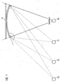
- Fig. 1 schematically shows a plan view of different positions P0, P1, P2, P3 of a viewer relative to a display screen 10 of a video display apparatus. Only when the viewer is positioned somewhere in a plane equidistant between the two horizontal extremities of the display screen 10, is the viewer in a "sweetspot", as represented in Fig. 1 by position P0. In this position, a pair of spatially separated microphones, each respectively located adjacent one of the two horizontal extremities of the display screen 10, will receive the same sound emitted by the viewer as each other. In all other positions, such as those represented by P1, P2, P3 in Fig. 1 , the viewer is at a greater distance from one of the two horizontal extremities of the display screen 10 than from the other.
- the sound received by one of the pair of spatially separated microphones located adjacent one of the horizontal extremities of the display screen 10 will be different from the sound received by the other such microphone so that it is possible to effectively separate the sound emitted by the loudspeaker from a surrounding sound received by the microphones.
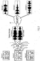
- Fig. 2 schematically represents separating and processing sound signals received from a plurality of different sound sources Source 1, Source 2, Source 3 by stereo microphones 1, 2 by means of an audio signal processing unit 20.
- the stereo microphones 1, 2 produce left and right channel audio signals as illustrated in Fig. 2 .
- the audio signal processing unit 20 compares these left and right channel audio signals and extracts from them estimates Estimate 1, Estimate 2, Estimate 3, each of which respectively corresponds to one of the sounds produced by Source 1, Source 2, Source 3.
- Fig. 3 schematically represents an embodiment of a video display apparatus 100.
- the video display apparatus 100 comprises a display screen 10 and a plurality of spatially separated microphones 1, 2, 3.
- the microphones 1, 2, 3 are located adjacent the display screen and are arranged in a triangle.
- the pair of microphones 1, 2 are spatially separated from each other by more than 400 mm
- the pair of microphones 2, 3 are spatially separated from each other by more than 500 mm
- the pair of microphones 1, 3 are spatially separated from each other by more than 600 mm.
- the video display apparatus 100 further comprises several loudspeakers (not visible in Fig. 3 ) for emitting a sound in association with the display of at least one still or moving image on the display screen 10.
- the video display apparatus 100 also contains a television receiver and an audio signal processing unit, neither of which are visible in Fig. 3 .
- the audio signal processing unit is configured to separate the sound emitted by the loudspeakers from a sound received by the microphones 1, 2, 3.
- Fig. 4 schematically represents a method of calculating the distances in three-dimensions of a plurality of spatially separated microphones, Mic 0, Mic 1, Mic 2, Mic 3 from a single source of sound, S.
- the sound source, S is located at co-ordinates x, y, z in an arbitrarily defined three-dimensional Cartesian co-ordinate system and emits a sound at time, t.
- the plurality of spatially separated microphones, Mic 0, Mic 1, Mic 2, Mic 3 comprises four different combinations of three microphones arranged in a triangle.
- Mic 0 is located at co-ordinates x0, y0, z0 and receives the sound from source S at time to.
- Mic 1 is located at co-ordinates x1, y1, z1 and receives the sound from source S at time t1.
- Mic 2 is located at co-ordinates x2, y2, z2 and receives the sound from source S at time t2.
- Mic 3 is located at co-ordinates x3, y3, z3 and receives the sound from source S at time t3.
- the distance (x0 - x, y0 - y, z0 - z) of Mic 0 from the sound source S is therefore given by the speed of sound, c, multiplied by the difference between the time, t0, of reception of the sound by Mic 0 and the time, t, of its emission: c*(t0 - t).
- the distance of Mic 1 from the sound source S is given by c*(t1-t)
- the distance of Mic 2 from the sound source S is given by c*(t2-t)
- the distance of Mic 3 from the sound source S is given by c*(t3 -t).
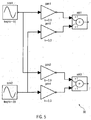
- Fig. 5 schematically represents how two different sound signals respectively received from two different sources of sound may be modelled.
- a first sound signal sine1 having a frequency of 10 Hz is emitted from a first source of sound and a second sound signal sine2 having a frequency of 20 Hz is emitted from a second source of sound.
- sine1 and sine2 are both represented as having a sinusoidal waveform, although in practice, they may have any waveform and any other audio frequency or range of frequencies.
- Sine1 and sine2 are both received by each one of a pair of spatially separated microphones.
- the first microphone may be modelled by two amplifiers gain1, gain2 and by an adder labelled add1 in Fig. 5 .
- Fig. 6 schematically represents two sound signals 61, 62, each respectively received by one of two spatially separated microphones from a single, common source.
- the graph of Fig. 6 plots the amplitude, A, of the two sound signals 61, 62 on the y-axis or ordinate against time, t, on the x-axis or abscissa. As may be seen from Fig.
- the two sound signals 61, 62 have the same frequency as each other and a similar waveform to each other (which, for the sake of this example, is a sinusoid) the amplitude A of the sound signal 61 differs from that of the sound signal 62, since the common source of the two signals 61, 62 is located further from one of the two microphones than the other.
- Fig. 7 schematically represents sound wave power dissipation over distance.
- the graph of Fig. 7 plots the amplitude, A, of a sound wave 71 on the y-axis or ordinate against distance, x, on the x-axis or abscissa from the emission of the sound wave 71 by a source, S, to its reception, R.
- the amplitude, A, of the sound wave 71 progressively diminishes between the source, S, and its reception, R.
- the power of the sound wave 71 which is proportional to the square of the amplitude, A, therefore also dissipates accordingly.
- the present invention provides a video display apparatus at least comprising a display screen, at least one loudspeaker for emitting a sound in association with at least one still or moving image displayed on the display screen, at least two spatially separated microphones, and an audio signal processing unit configured to separate the sound emitted by the loudspeaker from a sound received by the microphones.
- the present invention also provides a method of operating a video display apparatus, wherein the method at least comprises displaying on a display screen of the apparatus at least one still or moving image, emitting a sound from a loudspeaker of the apparatus in association with displaying the at least one still or moving image, receiving a sound by at least two spatially separated microphones of the apparatus, and separating the sound emitted from the loudspeaker from the sound received by the microphones.
- a method allows for three-dimensional localization and separation of sound sources to receive and execute voice commands for control of a video display apparatus, such as a television, without the need for a remote control.
Landscapes
- Health & Medical Sciences (AREA)
- General Health & Medical Sciences (AREA)
- Otolaryngology (AREA)
- Physics & Mathematics (AREA)
- Engineering & Computer Science (AREA)
- Acoustics & Sound (AREA)
- Signal Processing (AREA)
- Testing, Inspecting, Measuring Of Stereoscopic Televisions And Televisions (AREA)
- Controls And Circuits For Display Device (AREA)
- Circuit For Audible Band Transducer (AREA)
Abstract
Description
- The present invention relates to a video display apparatus according to
claim 1 and to a method of operating a video display apparatus according to claim 12. - At present, video display apparatuses, such as televisions, video games machines and computer monitors, are typically operated either by touch, using one or more push buttons, a keyboard, keypad, joystick, and/or touch screen of the display apparatus, or by transmitting electromagnetic signals to the apparatus, for example, infrared or radio waves, using a separate device, such as a dedicated remote control and/or smart phone. It is hard to operate a video display apparatus using sound, such as voice commands, because apart from comprising a display screen, such a video display apparatus typically also comprises at least one loudspeaker, which itself emits sound in association with still or moving images displayed on the display screen, for example as a sound track accompanying a film or television programme or as sound effects accompanying a video game. It is difficult for sound signals intended to operate the video display apparatus to be discriminated from these sounds emitted by the display apparatus itself, as well as from echoes, which are hard to model and predict, and from background noise.
- It is therefore an object of the invention to provide a video display apparatus and a method of operating a video display apparatus.
- The object of the invention is solved by a video display apparatus according to
claim 1. The video display apparatus at least comprises a display screen, at least one loudspeaker for emitting a sound in association with at least one still or moving image displayed on the display screen, at least two spatially separated microphones, and an audio signal processing unit configured to separate the sound emitted by the loudspeaker from a sound received by the microphones. - This solution is beneficial since such a video display apparatus is relatively much larger than a portable device like a remote control unit or a smart phone, so that the at least two microphones can be positioned sufficiently far apart from each other to give good spatial resolution for discriminating sound sources from each other. Moreover, since the audio signal processing unit can receive the sound emitted by the loudspeaker directly as an electronic signal before, during or after its emission, the sound emitted by the loudspeaker can be separated from the sound received by the microphones with a high degree of certainty and echoes can be easily identified and accounted for.
- Advantageous embodiments of the invention may be configured according to any claim and/or part of the following description.
- At least one of the microphones is preferably located adjacent the display screen, facing the same direction as the display screen. This improves the chances that at least one of the microphones will be facing a viewer of the display screen. More preferably, at least two of the microphones are located on either side of the display screen with the display screen between them, facing the same direction as the display screen. This is beneficial in increasing the horizontal resolution of the microphones.
- Preferably, at least one pair of the at least two microphones are spatially separated by at least 400 mm, more preferably by at least 500 mm, more preferably still by at least 600 mm, and most preferably by at least 700 mm from each other. This is advantageous because the spatial resolution of the microphones increases in proportion to their spatial separation.
- In a preferred embodiment, the at least two microphones comprise three microphones arranged in a triangle. This is beneficial because it allows sound sources to be discriminated from each other in two dimensions. For example, if the triangle has one horizontal and one vertical side, this will give corresponding spatial resolution of sound sources in the horizontal and vertical directions.
- Preferably, the video display apparatus further comprises a sound source locating unit. The sound source locating unit may locate the source of sounds, based upon the differences between the sound signals received by different ones of the at least two microphones. For example, the sound source locating unit may locate the source of sounds based on the different times of arrival of the sound from a single, common source at different ones of the at least two microphones.
- Preferably, the video display apparatus further comprises a voice recognition unit. This is beneficial because it can allow the video display apparatus to adopt one of a plurality of different user profiles according to the voice of a user recognized by the voice recognition unit.
- If so, the video display apparatus preferably further also comprises a voice command execution unit. This is beneficial because it can allow the video display apparatus to be controlled by a user issuing voice commands, such as "switch to channel A", "increase volume", and so on, without the need for a separate control device, such as a dedicated remote control or a smart phone. It also allows the video display apparatus to be used in hands-free multimedia and gaming applications.
- In one possible embodiment, the video display apparatus further comprises a multi-view display unit configured to display at least two different still or moving images on the display screen simultaneously. Multi-view is an existing display technology allowing at least two different still or moving images to be displayed on the display screen simultaneously, for example by displaying the different images with different polarizations from each other. A plurality of viewers with multi-view glasses of correspondingly different polarizations may then watch respective ones of the different still or moving images simultaneously without the need for a split screen. For example, one viewer may watch a film or television programme whilst another viewer browses an album of photos or plays a video game on the same display screen. Typically in such a case, one or more viewers may wear head or earphones supplied by the video display apparatus with a respective sound signal appropriate to the image or images being watched by the viewer in question.
- If so, and if the video display apparatus also comprises a sound source locating unit and a voice command execution unit, the voice command execution unit is preferably configured to execute a command in relation to a respective one of the simultaneously displayed still or moving images and/or a sound signal generated by the video display apparatus according to a location of a sound source issuing the command identified by the sound source locating unit. This is beneficial because a plurality of viewers of the display screen may then control whatever they are watching by issuing one or more voice commands which only affect the images they are viewing and/or the sound signal they are receiving and not the different images or sound of another simultaneous viewer. It also allows for display of the different images and/or the corresponding sound signals to be adapted to the respective locations of the simultaneous viewers. For example, the respective images may track the location of a viewer as they move. According to this example, if two simultaneous viewers swap positions, one of the viewers may call out "I'm over here" as a voice command, and the video display apparatus may then redirect the displayed images and/or the accompanying sound signals accordingly.
- In one possible embodiment, the video display apparatus may further comprise a television receiver. This allows the video display apparatus to display television programmes and for the programmes to be selected and controlled using voice commands, instead of using a separate device, such as a dedicated remote control or smart phone.
- Preferably, the audio signal processing unit is further configured to separate environmental noise from the sound received by the microphones. This is beneficial because it can be used to improve the accuracy of sound source location, voice recognition and execution of voice commands. The separation of environmental noise from the sound received by the microphones may be carried out by sampling the sound received by the microphones at times when the loudspeaker of the video display apparatus is silent and when no rapid variations in the volume of sound received by the microphones is detected, which might otherwise be indicative of a user's voice, and then using these samples as examples of environmental noise.
- The present invention further relates to a method of operating a video display apparatus. The method at least comprises displaying on a display screen of the apparatus at least one still or moving image, emitting a sound from a loudspeaker of the apparatus in association with displaying the at least one still or moving image, receiving a sound by at least two spatially separated microphones of the apparatus, and separating the sound emitted from the loudspeaker from the sound received by the microphones.
- Preferably, the method further comprises locating at least one source of the sound received by the microphones.
- Preferably, the method further comprises recognizing at least one voice in the sound received by the microphones.
- If so, the method preferably further comprises executing a command issued by the at least one voice according to the location of the sound source issuing the command.
- The present invention further relates to a computer program product or a program code or system for executing one or more than one of the herein described methods.
- Further features, goals and advantages of the present invention will now be described in association with the accompanying drawings, in which exemplary components of the invention are illustrated. Components of the apparatuses and methods according to the invention which are at least essentially equivalent to each other with respect to their function can be marked by the same reference numerals, wherein such components do not have to be marked or described in all of the drawings.
- In the following description, the invention is described by way of example only with respect to the accompanying drawings.
-
-
Fig. 1 is a schematic plan view of different viewer positions relative to a display screen of a video display apparatus; -
Fig. 2 is a schematic diagram of separating and processing sound signals received from a plurality of different sources by stereo microphones; -
Fig. 3 is a schematic representation of an embodiment of a video display apparatus comprising a plurality of spatially separated microphones; -
Fig. 4 schematically represents a three-dimensional method of calculating the distances of a plurality of spatially separated microphones from a single source of sound; -
Fig. 5 is a schematic block diagram of signal processing sound signals from two different sources; -
Fig. 6 is a graph representing sound signals received from a single source by two spatially separated microphones; and -
Fig. 7 is a graph representing sound wave power dissipation over distance. -
Fig. 1 schematically shows a plan view of different positions P0, P1, P2, P3 of a viewer relative to adisplay screen 10 of a video display apparatus. Only when the viewer is positioned somewhere in a plane equidistant between the two horizontal extremities of thedisplay screen 10, is the viewer in a "sweetspot", as represented inFig. 1 by position P0. In this position, a pair of spatially separated microphones, each respectively located adjacent one of the two horizontal extremities of thedisplay screen 10, will receive the same sound emitted by the viewer as each other. In all other positions, such as those represented by P1, P2, P3 inFig. 1 , the viewer is at a greater distance from one of the two horizontal extremities of thedisplay screen 10 than from the other. In any one of these other positions, the sound received by one of the pair of spatially separated microphones located adjacent one of the horizontal extremities of thedisplay screen 10 will be different from the sound received by the other such microphone so that it is possible to effectively separate the sound emitted by the loudspeaker from a surrounding sound received by the microphones. -
Fig. 2 schematically represents separating and processing sound signals received from a plurality of differentsound sources Source 1,Source 2,Source 3 bystereo microphones signal processing unit 20. Thestereo microphones Fig. 2 . The audiosignal processing unit 20 compares these left and right channel audio signals and extracts from them estimatesEstimate 1,Estimate 2,Estimate 3, each of which respectively corresponds to one of the sounds produced bySource 1,Source 2,Source 3. -
Fig. 3 schematically represents an embodiment of avideo display apparatus 100. Thevideo display apparatus 100 comprises adisplay screen 10 and a plurality of spatially separatedmicrophones microphones microphones microphones microphones - The
video display apparatus 100 further comprises several loudspeakers (not visible inFig. 3 ) for emitting a sound in association with the display of at least one still or moving image on thedisplay screen 10. Thevideo display apparatus 100 also contains a television receiver and an audio signal processing unit, neither of which are visible inFig. 3 . The audio signal processing unit is configured to separate the sound emitted by the loudspeakers from a sound received by themicrophones -
Fig. 4 schematically represents a method of calculating the distances in three-dimensions of a plurality of spatially separated microphones,Mic 0,Mic 1,Mic 2,Mic 3 from a single source of sound, S. In this example, the sound source, S, is located at co-ordinates x, y, z in an arbitrarily defined three-dimensional Cartesian co-ordinate system and emits a sound at time, t. As may be seen fromFig. 4 , the plurality of spatially separated microphones,Mic 0,Mic 1,Mic 2,Mic 3 comprises four different combinations of three microphones arranged in a triangle.Mic 0 is located at co-ordinates x0, y0, z0 and receives the sound from source S at time to.Mic 1 is located at co-ordinates x1, y1, z1 and receives the sound from source S at time t1. Similarly,Mic 2 is located at co-ordinates x2, y2, z2 and receives the sound from source S at time t2. Finally,Mic 3 is located at co-ordinates x3, y3, z3 and receives the sound from source S at time t3. The distance = (x0 - x, y0 - y, z0 - z) ofMic 0 from the sound source S is therefore given by the speed of sound, c, multiplied by the difference between the time, t0, of reception of the sound byMic 0 and the time, t, of its emission: c*(t0 - t). Similarly, the distance ofMic 1 from the sound source S is given by c*(t1-t), the distance ofMic 2 from the sound source S is given by c*(t2-t), and the distance ofMic 3 from the sound source S is given by c*(t3 -t). Thus by comparing the different times of reception of the sound at thedifferent microphones Mic 0,Mic 1,Mic 2,Mic 3, the location x, y, z of the sound source in the co-ordinate system may be calculated. Such a method as that described in relation toFig. 4 may be carried out by a sound source locating unit of a video display apparatus according to an embodiment of the invention. -
Fig. 5 schematically represents how two different sound signals respectively received from two different sources of sound may be modelled. In the example shown inFig. 5 , a first sound signal sine1 having a frequency of 10 Hz is emitted from a first source of sound and a second sound signal sine2 having a frequency of 20 Hz is emitted from a second source of sound. Purely for the sake of this example, sine1 and sine2 are both represented as having a sinusoidal waveform, although in practice, they may have any waveform and any other audio frequency or range of frequencies. Sine1 and sine2 are both received by each one of a pair of spatially separated microphones. The first microphone may be modelled by two amplifiers gain1, gain2 and by an adder labelled add1 inFig. 5 . The second microphone may be modelled by two further amplifiers gain3, gain4 and by a second adder labelled add2. Since the first sound source is nearer to the first microphone than it is to the second, the sound signal sine1 may be modelled as passing through the amplifier gain1 with a gain, k = 0.9 and through the amplifier gain3 with a gain of only k = 0.3. On the other hand, since the second sound source is nearer to the second microphone than it is to the first, the sound signal sine2 may instead be modelled as passing through the amplifier gain2 with a gain of only k = 0.3 and through the amplifier gain4 with a gain, k = 0.9. Subsequent to these respective amplifications, the sound signals sine1, sine2 are added to each other by the adders add1, add2 of each microphone as shown inFig. 5 . -
Fig. 6 schematically represents twosound signals 61, 62, each respectively received by one of two spatially separated microphones from a single, common source. The graph ofFig. 6 plots the amplitude, A, of the two sound signals 61, 62 on the y-axis or ordinate against time, t, on the x-axis or abscissa. As may be seen fromFig. 6 , whereas the two sound signals 61, 62 have the same frequency as each other and a similar waveform to each other (which, for the sake of this example, is a sinusoid) the amplitude A of the sound signal 61 differs from that of thesound signal 62, since the common source of the twosignals 61, 62 is located further from one of the two microphones than the other. -
Fig. 7 schematically represents sound wave power dissipation over distance. The graph ofFig. 7 plots the amplitude, A, of asound wave 71 on the y-axis or ordinate against distance, x, on the x-axis or abscissa from the emission of thesound wave 71 by a source, S, to its reception, R. As may be seen fromFig. 7 , the amplitude, A, of thesound wave 71 progressively diminishes between the source, S, and its reception, R. The power of thesound wave 71, which is proportional to the square of the amplitude, A, therefore also dissipates accordingly. - In summary, therefore, the present invention provides a video display apparatus at least comprising a display screen, at least one loudspeaker for emitting a sound in association with at least one still or moving image displayed on the display screen, at least two spatially separated microphones, and an audio signal processing unit configured to separate the sound emitted by the loudspeaker from a sound received by the microphones. The present invention also provides a method of operating a video display apparatus, wherein the method at least comprises displaying on a display screen of the apparatus at least one still or moving image, emitting a sound from a loudspeaker of the apparatus in association with displaying the at least one still or moving image, receiving a sound by at least two spatially separated microphones of the apparatus, and separating the sound emitted from the loudspeaker from the sound received by the microphones. Such a method allows for three-dimensional localization and separation of sound sources to receive and execute voice commands for control of a video display apparatus, such as a television, without the need for a remote control.
Reference Numerals: 1,2,3 Spatially separated microphones gain1, gain2, gain3, gain4 Amplifiers 10 Display screen 20 Audio signal processing unit Mic 0, Mic 1,Mic 2,Mic 3Plurality of spatially separated microphones 30 Model of two sound signals 61 First audio signal 62 Second audio signal P0, P1, P2, P3 Different positions of viewer 71 Sound wave 100 Video display apparatus R Reception A Amplitude S Sound source add1, add2 Adders Source 1, Source 2,Source 3Plurality of sound sources Estimate 1, Estimate 2,Estimate 3Estimates of sounds produced by sound sources sine1, sine2 Different sound signals t Time x Distance
Claims (15)
- A video display apparatus (100) at least comprising:a display screen (10);at least one loudspeaker for emitting a sound in association with at least one still or moving image displayed on the display screen (10);at least two spatially separated microphones (1, 2, 3; Mic 0, Mic 1, Mic 2, Mic 3); andan audio signal processing unit (20) configured to separate the sound emitted by the loudspeaker from a sound received by the microphones.
- A video display apparatus according to claim 1, wherein at least one of the microphones (1, 2, 3; Mic 0, Mic 1, Mic 2, Mic 3) is located adjacent the display screen (10), facing the same direction as the display screen.
- A video display apparatus according to claim 1 or claim 2, wherein at least one pair (1, 2; 2, 3; 1, 3) of the at least two microphones (1, 2, 3; Mic 0, Mic 1, Mic 2, Mic 3) are spatially separated from each other by at least 400 mm.
- A video display apparatus according to any one of the preceding claims, wherein the at least two microphones (1, 2, 3; Mic 0, Mic 1, Mic 2, Mic 3) comprise three microphones arranged in a triangle.
- A video display apparatus according to any one of the preceding claims, further comprising a sound source locating unit.
- A video display apparatus according to any one of the preceding claims, further comprising a voice recognition unit.
- A video display apparatus according to claim 6, further comprising a voice command execution unit.
- A video display apparatus according to any one of the preceding claims, further comprising a multi-view display unit configured to display at least two different still or moving images on the display screen (10) simultaneously.
- A video display apparatus according to claim 8 as dependent on claim 7 and claim 5, wherein the voice command execution unit is configured to execute a command in relation to at least one of a respective one of the simultaneously displayed still or moving images and a sound signal generated by the video display apparatus according to a location of a sound source (S) issuing the command identified by the sound source locating unit.
- A video display apparatus according to any one of the preceding claims, further comprising a television receiver.
- A video display apparatus according to any one of the preceding claims, wherein the audio signal processing unit (20) is further configured to separate environmental noise from the sound received by the microphones (1, 2, 3; Mic 0, Mic 1, Mic 2, Mic 3).
- A method of operating a video display apparatus (100), the method at least comprising:displaying on a display screen (10) of the apparatus at least one still or moving image;emitting a sound from a loudspeaker of the apparatus in association with displaying the at least one still or moving image;receiving a sound by at least two spatially separated microphones (1, 2, 3; Mic 0, Mic 1, Mic 2, Mic 3) of the apparatus; andseparating the sound emitted from the loudspeaker from the sound received by the microphones.
- A method according to claim 12, further comprising locating at least one source (S) of the sound received by the microphones (1, 2, 3; Mic 0, Mic 1, Mic 2, Mic 3).
- A method according to claim 12 or claim 13, further comprising recognizing at least one voice in the sound received by the microphones (1, 2, 3; Mic 0, Mic 1, Mic 2, Mic 3).
- A method according to claim 14 as dependent on claim 13, further comprising executing a command issued by the at least one voice according to the location of the sound source (S) issuing the command.
Priority Applications (2)
| Application Number | Priority Date | Filing Date | Title |
|---|---|---|---|
| EP17151645.3A EP3349480B1 (en) | 2017-01-16 | 2017-01-16 | Video display apparatus and method of operating the same |
| TR2017/02870A TR201702870A2 (en) | 2017-01-16 | 2017-02-24 | Video display apparatus and method of operating the same. |
Applications Claiming Priority (1)
| Application Number | Priority Date | Filing Date | Title |
|---|---|---|---|
| EP17151645.3A EP3349480B1 (en) | 2017-01-16 | 2017-01-16 | Video display apparatus and method of operating the same |
Publications (2)
| Publication Number | Publication Date |
|---|---|
| EP3349480A1 true EP3349480A1 (en) | 2018-07-18 |
| EP3349480B1 EP3349480B1 (en) | 2020-09-02 |
Family
ID=57860671
Family Applications (1)
| Application Number | Title | Priority Date | Filing Date |
|---|---|---|---|
| EP17151645.3A Active EP3349480B1 (en) | 2017-01-16 | 2017-01-16 | Video display apparatus and method of operating the same |
Country Status (2)
| Country | Link |
|---|---|
| EP (1) | EP3349480B1 (en) |
| TR (1) | TR201702870A2 (en) |
Cited By (1)
| Publication number | Priority date | Publication date | Assignee | Title |
|---|---|---|---|---|
| US11263798B2 (en) | 2019-05-31 | 2022-03-01 | Imagination Technologies Limited | Multi-rendering in graphics processing units using render progression checks |
Citations (4)
| Publication number | Priority date | Publication date | Assignee | Title |
|---|---|---|---|---|
| EP1835478A1 (en) * | 2004-12-14 | 2007-09-19 | Fujitsu Ten Limited | Display device, frame member and reflection suppressing member |
| EP2923634A1 (en) * | 2014-03-27 | 2015-09-30 | Storz Endoskop Produktions GmbH | Multi-user voice control system for medical devices |
| US20160212525A1 (en) * | 2015-01-15 | 2016-07-21 | Honda Motor Co., Ltd. | Sound source localization device, sound processing system, and control method of sound source localization device |
| US20160259305A1 (en) * | 2014-08-22 | 2016-09-08 | Boe Technology Group Co., Ltd. | Display device and method for regulating viewing angle of display device |
Family Cites Families (2)
| Publication number | Priority date | Publication date | Assignee | Title |
|---|---|---|---|---|
| CN1826797A (en) * | 2003-05-27 | 2006-08-30 | 皇家飞利浦电子股份有限公司 | Loudspeaker-microphone system with echo cancellation system and echo cancellation method |
| WO2014064325A1 (en) * | 2012-10-26 | 2014-05-01 | Nokia Corporation | Media remixing system |
-
2017
- 2017-01-16 EP EP17151645.3A patent/EP3349480B1/en active Active
- 2017-02-24 TR TR2017/02870A patent/TR201702870A2/en unknown
Patent Citations (4)
| Publication number | Priority date | Publication date | Assignee | Title |
|---|---|---|---|---|
| EP1835478A1 (en) * | 2004-12-14 | 2007-09-19 | Fujitsu Ten Limited | Display device, frame member and reflection suppressing member |
| EP2923634A1 (en) * | 2014-03-27 | 2015-09-30 | Storz Endoskop Produktions GmbH | Multi-user voice control system for medical devices |
| US20160259305A1 (en) * | 2014-08-22 | 2016-09-08 | Boe Technology Group Co., Ltd. | Display device and method for regulating viewing angle of display device |
| US20160212525A1 (en) * | 2015-01-15 | 2016-07-21 | Honda Motor Co., Ltd. | Sound source localization device, sound processing system, and control method of sound source localization device |
Cited By (1)
| Publication number | Priority date | Publication date | Assignee | Title |
|---|---|---|---|---|
| US11263798B2 (en) | 2019-05-31 | 2022-03-01 | Imagination Technologies Limited | Multi-rendering in graphics processing units using render progression checks |
Also Published As
| Publication number | Publication date |
|---|---|
| EP3349480B1 (en) | 2020-09-02 |
| TR201702870A2 (en) | 2018-07-23 |
Similar Documents
| Publication | Publication Date | Title |
|---|---|---|
| US10587979B2 (en) | Localization of sound in a speaker system | |
| US10206030B2 (en) | Microphone array system and microphone array control method | |
| US11758329B2 (en) | Audio mixing based upon playing device location | |
| US10694313B2 (en) | Audio communication system and method | |
| EP3342187B1 (en) | Suppressing ambient sounds | |
| US20150264502A1 (en) | Audio Signal Processing Device, Position Information Acquisition Device, and Audio Signal Processing System | |
| JP2013529004A (en) | Speaker with position tracking | |
| CN109314834A (en) | Improve the perception of sound objects that mediate reality | |
| US20210266692A1 (en) | Information processing device, information processing method, and information processing system | |
| CN108028976A (en) | Distributed audio microphone array and locator configuration | |
| US20200177993A1 (en) | Recording and Rendering Sound Spaces | |
| KR102454761B1 (en) | Method for operating an apparatus for displaying image | |
| US10979806B1 (en) | Audio system having audio and ranging components | |
| CN102057693B (en) | Content reproduction device and content reproduction method | |
| EP3731537A1 (en) | Systems and methods in tiled display imaging systems | |
| CN116261094B (en) | A sound system that can dynamically adjust the target listening point and eliminate interference from environmental objects. | |
| EP3349480B1 (en) | Video display apparatus and method of operating the same | |
| CN109002272A (en) | Interactive directional sound display system and interactive directional sound display method | |
| US10136216B2 (en) | Action sound capture using subsurface microphones | |
| JP2009065292A (en) | Program simultaneous viewing system, program simultaneous viewing method, and program simultaneous viewing program | |
| KR102348658B1 (en) | Display device and driving method thereof | |
| JP3843743B2 (en) | Robot audio-visual system | |
| KR101505099B1 (en) | System for supply 3-dimension sound | |
| KR102284914B1 (en) | A sound tracking system with preset images | |
| JP3255766B2 (en) | Sound localization system |
Legal Events
| Date | Code | Title | Description |
|---|---|---|---|
| PUAI | Public reference made under article 153(3) epc to a published international application that has entered the european phase |
Free format text: ORIGINAL CODE: 0009012 |
|
| STAA | Information on the status of an ep patent application or granted ep patent |
Free format text: STATUS: THE APPLICATION HAS BEEN PUBLISHED |
|
| AK | Designated contracting states |
Kind code of ref document: A1 Designated state(s): AL AT BE BG CH CY CZ DE DK EE ES FI FR GB GR HR HU IE IS IT LI LT LU LV MC MK MT NL NO PL PT RO RS SE SI SK SM TR |
|
| AX | Request for extension of the european patent |
Extension state: BA ME |
|
| STAA | Information on the status of an ep patent application or granted ep patent |
Free format text: STATUS: REQUEST FOR EXAMINATION WAS MADE |
|
| 17P | Request for examination filed |
Effective date: 20190115 |
|
| RBV | Designated contracting states (corrected) |
Designated state(s): AL AT BE BG CH CY CZ DE DK EE ES FI FR GB GR HR HU IE IS IT LI LT LU LV MC MK MT NL NO PL PT RO RS SE SI SK SM TR |
|
| STAA | Information on the status of an ep patent application or granted ep patent |
Free format text: STATUS: EXAMINATION IS IN PROGRESS |
|
| 17Q | First examination report despatched |
Effective date: 20191025 |
|
| GRAP | Despatch of communication of intention to grant a patent |
Free format text: ORIGINAL CODE: EPIDOSNIGR1 |
|
| STAA | Information on the status of an ep patent application or granted ep patent |
Free format text: STATUS: GRANT OF PATENT IS INTENDED |
|
| INTG | Intention to grant announced |
Effective date: 20200402 |
|
| RIC1 | Information provided on ipc code assigned before grant |
Ipc: H04R 3/00 20060101AFI20200320BHEP Ipc: H04S 7/00 20060101ALN20200320BHEP |
|
| GRAS | Grant fee paid |
Free format text: ORIGINAL CODE: EPIDOSNIGR3 |
|
| GRAA | (expected) grant |
Free format text: ORIGINAL CODE: 0009210 |
|
| STAA | Information on the status of an ep patent application or granted ep patent |
Free format text: STATUS: THE PATENT HAS BEEN GRANTED |
|
| AK | Designated contracting states |
Kind code of ref document: B1 Designated state(s): AL AT BE BG CH CY CZ DE DK EE ES FI FR GB GR HR HU IE IS IT LI LT LU LV MC MK MT NL NO PL PT RO RS SE SI SK SM TR |
|
| REG | Reference to a national code |
Ref country code: GB Ref legal event code: FG4D |
|
| REG | Reference to a national code |
Ref country code: AT Ref legal event code: REF Ref document number: 1310211 Country of ref document: AT Kind code of ref document: T Effective date: 20200915 Ref country code: CH Ref legal event code: EP |
|
| REG | Reference to a national code |
Ref country code: DE Ref legal event code: R096 Ref document number: 602017022587 Country of ref document: DE |
|
| REG | Reference to a national code |
Ref country code: IE Ref legal event code: FG4D |
|
| REG | Reference to a national code |
Ref country code: LT Ref legal event code: MG4D |
|
| PG25 | Lapsed in a contracting state [announced via postgrant information from national office to epo] |
Ref country code: LT Free format text: LAPSE BECAUSE OF FAILURE TO SUBMIT A TRANSLATION OF THE DESCRIPTION OR TO PAY THE FEE WITHIN THE PRESCRIBED TIME-LIMIT Effective date: 20200902 Ref country code: HR Free format text: LAPSE BECAUSE OF FAILURE TO SUBMIT A TRANSLATION OF THE DESCRIPTION OR TO PAY THE FEE WITHIN THE PRESCRIBED TIME-LIMIT Effective date: 20200902 Ref country code: BG Free format text: LAPSE BECAUSE OF FAILURE TO SUBMIT A TRANSLATION OF THE DESCRIPTION OR TO PAY THE FEE WITHIN THE PRESCRIBED TIME-LIMIT Effective date: 20201202 Ref country code: SE Free format text: LAPSE BECAUSE OF FAILURE TO SUBMIT A TRANSLATION OF THE DESCRIPTION OR TO PAY THE FEE WITHIN THE PRESCRIBED TIME-LIMIT Effective date: 20200902 Ref country code: GR Free format text: LAPSE BECAUSE OF FAILURE TO SUBMIT A TRANSLATION OF THE DESCRIPTION OR TO PAY THE FEE WITHIN THE PRESCRIBED TIME-LIMIT Effective date: 20201203 Ref country code: NO Free format text: LAPSE BECAUSE OF FAILURE TO SUBMIT A TRANSLATION OF THE DESCRIPTION OR TO PAY THE FEE WITHIN THE PRESCRIBED TIME-LIMIT Effective date: 20201202 Ref country code: FI Free format text: LAPSE BECAUSE OF FAILURE TO SUBMIT A TRANSLATION OF THE DESCRIPTION OR TO PAY THE FEE WITHIN THE PRESCRIBED TIME-LIMIT Effective date: 20200902 |
|
| REG | Reference to a national code |
Ref country code: NL Ref legal event code: MP Effective date: 20200902 |
|
| REG | Reference to a national code |
Ref country code: AT Ref legal event code: MK05 Ref document number: 1310211 Country of ref document: AT Kind code of ref document: T Effective date: 20200902 |
|
| PG25 | Lapsed in a contracting state [announced via postgrant information from national office to epo] |
Ref country code: RS Free format text: LAPSE BECAUSE OF FAILURE TO SUBMIT A TRANSLATION OF THE DESCRIPTION OR TO PAY THE FEE WITHIN THE PRESCRIBED TIME-LIMIT Effective date: 20200902 Ref country code: LV Free format text: LAPSE BECAUSE OF FAILURE TO SUBMIT A TRANSLATION OF THE DESCRIPTION OR TO PAY THE FEE WITHIN THE PRESCRIBED TIME-LIMIT Effective date: 20200902 Ref country code: PL Free format text: LAPSE BECAUSE OF FAILURE TO SUBMIT A TRANSLATION OF THE DESCRIPTION OR TO PAY THE FEE WITHIN THE PRESCRIBED TIME-LIMIT Effective date: 20200902 |
|
| PG25 | Lapsed in a contracting state [announced via postgrant information from national office to epo] |
Ref country code: SM Free format text: LAPSE BECAUSE OF FAILURE TO SUBMIT A TRANSLATION OF THE DESCRIPTION OR TO PAY THE FEE WITHIN THE PRESCRIBED TIME-LIMIT Effective date: 20200902 Ref country code: EE Free format text: LAPSE BECAUSE OF FAILURE TO SUBMIT A TRANSLATION OF THE DESCRIPTION OR TO PAY THE FEE WITHIN THE PRESCRIBED TIME-LIMIT Effective date: 20200902 Ref country code: CZ Free format text: LAPSE BECAUSE OF FAILURE TO SUBMIT A TRANSLATION OF THE DESCRIPTION OR TO PAY THE FEE WITHIN THE PRESCRIBED TIME-LIMIT Effective date: 20200902 Ref country code: PT Free format text: LAPSE BECAUSE OF FAILURE TO SUBMIT A TRANSLATION OF THE DESCRIPTION OR TO PAY THE FEE WITHIN THE PRESCRIBED TIME-LIMIT Effective date: 20210104 Ref country code: RO Free format text: LAPSE BECAUSE OF FAILURE TO SUBMIT A TRANSLATION OF THE DESCRIPTION OR TO PAY THE FEE WITHIN THE PRESCRIBED TIME-LIMIT Effective date: 20200902 |
|
| PG25 | Lapsed in a contracting state [announced via postgrant information from national office to epo] |
Ref country code: AL Free format text: LAPSE BECAUSE OF FAILURE TO SUBMIT A TRANSLATION OF THE DESCRIPTION OR TO PAY THE FEE WITHIN THE PRESCRIBED TIME-LIMIT Effective date: 20200902 Ref country code: AT Free format text: LAPSE BECAUSE OF FAILURE TO SUBMIT A TRANSLATION OF THE DESCRIPTION OR TO PAY THE FEE WITHIN THE PRESCRIBED TIME-LIMIT Effective date: 20200902 Ref country code: ES Free format text: LAPSE BECAUSE OF FAILURE TO SUBMIT A TRANSLATION OF THE DESCRIPTION OR TO PAY THE FEE WITHIN THE PRESCRIBED TIME-LIMIT Effective date: 20200902 Ref country code: IS Free format text: LAPSE BECAUSE OF FAILURE TO SUBMIT A TRANSLATION OF THE DESCRIPTION OR TO PAY THE FEE WITHIN THE PRESCRIBED TIME-LIMIT Effective date: 20210102 |
|
| REG | Reference to a national code |
Ref country code: DE Ref legal event code: R097 Ref document number: 602017022587 Country of ref document: DE |
|
| PG25 | Lapsed in a contracting state [announced via postgrant information from national office to epo] |
Ref country code: SK Free format text: LAPSE BECAUSE OF FAILURE TO SUBMIT A TRANSLATION OF THE DESCRIPTION OR TO PAY THE FEE WITHIN THE PRESCRIBED TIME-LIMIT Effective date: 20200902 |
|
| PLBE | No opposition filed within time limit |
Free format text: ORIGINAL CODE: 0009261 |
|
| STAA | Information on the status of an ep patent application or granted ep patent |
Free format text: STATUS: NO OPPOSITION FILED WITHIN TIME LIMIT |
|
| 26N | No opposition filed |
Effective date: 20210603 |
|
| PG25 | Lapsed in a contracting state [announced via postgrant information from national office to epo] |
Ref country code: MC Free format text: LAPSE BECAUSE OF FAILURE TO SUBMIT A TRANSLATION OF THE DESCRIPTION OR TO PAY THE FEE WITHIN THE PRESCRIBED TIME-LIMIT Effective date: 20200902 Ref country code: SI Free format text: LAPSE BECAUSE OF FAILURE TO SUBMIT A TRANSLATION OF THE DESCRIPTION OR TO PAY THE FEE WITHIN THE PRESCRIBED TIME-LIMIT Effective date: 20200902 Ref country code: DK Free format text: LAPSE BECAUSE OF FAILURE TO SUBMIT A TRANSLATION OF THE DESCRIPTION OR TO PAY THE FEE WITHIN THE PRESCRIBED TIME-LIMIT Effective date: 20200902 |
|
| REG | Reference to a national code |
Ref country code: CH Ref legal event code: PL |
|
| PG25 | Lapsed in a contracting state [announced via postgrant information from national office to epo] |
Ref country code: LU Free format text: LAPSE BECAUSE OF NON-PAYMENT OF DUE FEES Effective date: 20210116 |
|
| REG | Reference to a national code |
Ref country code: BE Ref legal event code: MM Effective date: 20210131 |
|
| PG25 | Lapsed in a contracting state [announced via postgrant information from national office to epo] |
Ref country code: FR Free format text: LAPSE BECAUSE OF NON-PAYMENT OF DUE FEES Effective date: 20210131 Ref country code: IT Free format text: LAPSE BECAUSE OF FAILURE TO SUBMIT A TRANSLATION OF THE DESCRIPTION OR TO PAY THE FEE WITHIN THE PRESCRIBED TIME-LIMIT Effective date: 20200902 |
|
| PG25 | Lapsed in a contracting state [announced via postgrant information from national office to epo] |
Ref country code: CH Free format text: LAPSE BECAUSE OF NON-PAYMENT OF DUE FEES Effective date: 20210131 Ref country code: LI Free format text: LAPSE BECAUSE OF NON-PAYMENT OF DUE FEES Effective date: 20210131 |
|
| PG25 | Lapsed in a contracting state [announced via postgrant information from national office to epo] |
Ref country code: IE Free format text: LAPSE BECAUSE OF NON-PAYMENT OF DUE FEES Effective date: 20210116 |
|
| PG25 | Lapsed in a contracting state [announced via postgrant information from national office to epo] |
Ref country code: BE Free format text: LAPSE BECAUSE OF NON-PAYMENT OF DUE FEES Effective date: 20210131 |
|
| PG25 | Lapsed in a contracting state [announced via postgrant information from national office to epo] |
Ref country code: NL Free format text: LAPSE BECAUSE OF NON-PAYMENT OF DUE FEES Effective date: 20200923 Ref country code: CY Free format text: LAPSE BECAUSE OF FAILURE TO SUBMIT A TRANSLATION OF THE DESCRIPTION OR TO PAY THE FEE WITHIN THE PRESCRIBED TIME-LIMIT Effective date: 20200902 |
|
| PG25 | Lapsed in a contracting state [announced via postgrant information from national office to epo] |
Ref country code: HU Free format text: LAPSE BECAUSE OF FAILURE TO SUBMIT A TRANSLATION OF THE DESCRIPTION OR TO PAY THE FEE WITHIN THE PRESCRIBED TIME-LIMIT; INVALID AB INITIO Effective date: 20170116 |
|
| PG25 | Lapsed in a contracting state [announced via postgrant information from national office to epo] |
Ref country code: MK Free format text: LAPSE BECAUSE OF FAILURE TO SUBMIT A TRANSLATION OF THE DESCRIPTION OR TO PAY THE FEE WITHIN THE PRESCRIBED TIME-LIMIT Effective date: 20200902 |
|
| PG25 | Lapsed in a contracting state [announced via postgrant information from national office to epo] |
Ref country code: MT Free format text: LAPSE BECAUSE OF FAILURE TO SUBMIT A TRANSLATION OF THE DESCRIPTION OR TO PAY THE FEE WITHIN THE PRESCRIBED TIME-LIMIT Effective date: 20200902 |
|
| PGFP | Annual fee paid to national office [announced via postgrant information from national office to epo] |
Ref country code: GB Payment date: 20260123 Year of fee payment: 10 |
|
| PGFP | Annual fee paid to national office [announced via postgrant information from national office to epo] |
Ref country code: DE Payment date: 20260121 Year of fee payment: 10 |
|
| PGFP | Annual fee paid to national office [announced via postgrant information from national office to epo] |
Ref country code: TR Payment date: 20260114 Year of fee payment: 10 |