EP3349452A1 - Scaling of transform coefficients for non-dyadic transform blocks - Google Patents
Scaling of transform coefficients for non-dyadic transform blocks Download PDFInfo
- Publication number
- EP3349452A1 EP3349452A1 EP17305034.5A EP17305034A EP3349452A1 EP 3349452 A1 EP3349452 A1 EP 3349452A1 EP 17305034 A EP17305034 A EP 17305034A EP 3349452 A1 EP3349452 A1 EP 3349452A1
- Authority
- EP
- European Patent Office
- Prior art keywords
- block
- scaling factor
- power
- scaling
- transform
- Prior art date
- Legal status (The legal status is an assumption and is not a legal conclusion. Google has not performed a legal analysis and makes no representation as to the accuracy of the status listed.)
- Withdrawn
Links
- 238000000034 method Methods 0.000 claims abstract description 56
- 238000013139 quantization Methods 0.000 claims abstract description 43
- 230000001131 transforming effect Effects 0.000 claims abstract description 8
- 238000004891 communication Methods 0.000 description 17
- 241000023320 Luma <angiosperm> Species 0.000 description 10
- OSWPMRLSEDHDFF-UHFFFAOYSA-N methyl salicylate Chemical compound COC(=O)C1=CC=CC=C1O OSWPMRLSEDHDFF-UHFFFAOYSA-N 0.000 description 10
- 238000004590 computer program Methods 0.000 description 8
- 230000008569 process Effects 0.000 description 8
- 230000003287 optical effect Effects 0.000 description 5
- 238000000638 solvent extraction Methods 0.000 description 4
- 230000006870 function Effects 0.000 description 3
- 239000013598 vector Substances 0.000 description 3
- 208000037170 Delayed Emergence from Anesthesia Diseases 0.000 description 2
- 230000000295 complement effect Effects 0.000 description 2
- 238000010586 diagram Methods 0.000 description 2
- 230000007246 mechanism Effects 0.000 description 2
- 229920001690 polydopamine Polymers 0.000 description 2
- 239000004065 semiconductor Substances 0.000 description 2
- 101150114515 CTBS gene Proteins 0.000 description 1
- 230000003044 adaptive effect Effects 0.000 description 1
- 238000003491 array Methods 0.000 description 1
- 230000006835 compression Effects 0.000 description 1
- 238000007906 compression Methods 0.000 description 1
- 238000001914 filtration Methods 0.000 description 1
- 238000012986 modification Methods 0.000 description 1
- 230000004048 modification Effects 0.000 description 1
- 238000005192 partition Methods 0.000 description 1
- 238000001228 spectrum Methods 0.000 description 1
- 230000002123 temporal effect Effects 0.000 description 1
Images

Classifications
-
- H—ELECTRICITY
- H04—ELECTRIC COMMUNICATION TECHNIQUE
- H04N—PICTORIAL COMMUNICATION, e.g. TELEVISION
- H04N19/00—Methods or arrangements for coding, decoding, compressing or decompressing digital video signals
- H04N19/10—Methods or arrangements for coding, decoding, compressing or decompressing digital video signals using adaptive coding
- H04N19/102—Methods or arrangements for coding, decoding, compressing or decompressing digital video signals using adaptive coding characterised by the element, parameter or selection affected or controlled by the adaptive coding
- H04N19/124—Quantisation
- H04N19/126—Details of normalisation or weighting functions, e.g. normalisation matrices or variable uniform quantisers
-
- H—ELECTRICITY
- H04—ELECTRIC COMMUNICATION TECHNIQUE
- H04N—PICTORIAL COMMUNICATION, e.g. TELEVISION
- H04N19/00—Methods or arrangements for coding, decoding, compressing or decompressing digital video signals
- H04N19/10—Methods or arrangements for coding, decoding, compressing or decompressing digital video signals using adaptive coding
- H04N19/102—Methods or arrangements for coding, decoding, compressing or decompressing digital video signals using adaptive coding characterised by the element, parameter or selection affected or controlled by the adaptive coding
- H04N19/124—Quantisation
-
- H—ELECTRICITY
- H04—ELECTRIC COMMUNICATION TECHNIQUE
- H04N—PICTORIAL COMMUNICATION, e.g. TELEVISION
- H04N19/00—Methods or arrangements for coding, decoding, compressing or decompressing digital video signals
- H04N19/10—Methods or arrangements for coding, decoding, compressing or decompressing digital video signals using adaptive coding
- H04N19/134—Methods or arrangements for coding, decoding, compressing or decompressing digital video signals using adaptive coding characterised by the element, parameter or criterion affecting or controlling the adaptive coding
- H04N19/157—Assigned coding mode, i.e. the coding mode being predefined or preselected to be further used for selection of another element or parameter
-
- H—ELECTRICITY
- H04—ELECTRIC COMMUNICATION TECHNIQUE
- H04N—PICTORIAL COMMUNICATION, e.g. TELEVISION
- H04N19/00—Methods or arrangements for coding, decoding, compressing or decompressing digital video signals
- H04N19/10—Methods or arrangements for coding, decoding, compressing or decompressing digital video signals using adaptive coding
- H04N19/169—Methods or arrangements for coding, decoding, compressing or decompressing digital video signals using adaptive coding characterised by the coding unit, i.e. the structural portion or semantic portion of the video signal being the object or the subject of the adaptive coding
- H04N19/17—Methods or arrangements for coding, decoding, compressing or decompressing digital video signals using adaptive coding characterised by the coding unit, i.e. the structural portion or semantic portion of the video signal being the object or the subject of the adaptive coding the unit being an image region, e.g. an object
- H04N19/176—Methods or arrangements for coding, decoding, compressing or decompressing digital video signals using adaptive coding characterised by the coding unit, i.e. the structural portion or semantic portion of the video signal being the object or the subject of the adaptive coding the unit being an image region, e.g. an object the region being a block, e.g. a macroblock
-
- H—ELECTRICITY
- H04—ELECTRIC COMMUNICATION TECHNIQUE
- H04N—PICTORIAL COMMUNICATION, e.g. TELEVISION
- H04N19/00—Methods or arrangements for coding, decoding, compressing or decompressing digital video signals
- H04N19/60—Methods or arrangements for coding, decoding, compressing or decompressing digital video signals using transform coding
Definitions
- the present principles generally relate to a method and a device for image encoding and decoding, and more particularly, to a method and a device for image encoding and decoding with quantizing and inverse quantizing.
- video coding schemes usually employ prediction and transform to leverage spatial and temporal redundancy in the video content.
- intra or inter prediction is used to exploit the intra or inter frame correlation, then the differences between group of samples in the original image and in the prediction image, often denoted as residuals, are transformed, quantized and entropy coded.
- residuals the differences between group of samples in the original image and in the prediction image, often denoted as residuals.
- the compressed data is decoded by inverse processes corresponding to the prediction, transform, quantization and entropy coding.
- transform and quantization are applied on square blocks whose size in each dimension is equal to a power of 2, i.e. of size 2 M ⁇ 2 M .
- quantization comprises quantization by Qstep (S10) followed by scaling (S12) by a scaling factor S Q equal to 2 -(29- M - B ) where B is the bitdepth of the original image.
- the HEVC quantization and scaling are only adapted to square blocks whose width and/or height are/is a power of 2.
- a decoding method comprises:
- a decoding device that comprises:
- a decoding device comprising a communication interface and at least one processor is disclosed.
- the communication interface is configured to access at least a bitstream and the at least one processor is configured to:
- the scaling factor S IQ is proportional to 4 3 ⁇ 1 s 1 * s 2 where s1 is the width and s2 the height of the block or vice versa and where s 1 * is the smallest integer equal to a power of 2 that is greater than s1.
- the scaling factor S IQ is substantially equal to 4 3 ⁇ 1 s 1 * s 2 ⁇ 2 ⁇ B ⁇ 9 where B is the bitdepth of the image block.
- the scaling factor S IQ is proportional to 4 3 ⁇ 1 s 1 * s 2 * where s 1 * is the smallest integer equal to a power of 2 that is greater than s1 and where s 2 * is the smallest integer equal to a power of 2 that is greater than s2.
- the scaling factor S IQ is substantially equal to 4 3 ⁇ 1 s 1 * s 2 * ⁇ 2 ⁇ B ⁇ 9 where B is the bitdepth of the block.
- a coding is also disclosed that comprises:
- a coding device is also disclosed that comprises:
- a coding device comprising a communication interface and at least one processor is disclosed.
- the communication interface is configured to access an image block and the at least one processor is configured to:
- the scaling factor S Q is proportional to 3 4 ⁇ s 1 * s 2 where s1 is the width and s2 the height of the block or vice versa and where s 1 * is the smallest integer equal to a power of 2 that is greater than s1.
- the scaling factor S Q is substantially equal to 3 4 ⁇ s 1 * s 2 ⁇ 2 ⁇ 29 ⁇ B where B is the bitdepth of said image block.
- said scaling factor S Q is proportional to 3 4 ⁇ s 1 * s 2 * where s1 is the width and s2 the height of the block or vice versa and where s 1 * is the smallest integer equal to a power of 2 that is greater than s1 and where s 2 * is the smallest integer equal to a power of 2 that is greater than s2.
- the scaling factor S Q is substantially equal to 3 4 ⁇ s 1 * s 2 * ⁇ 2 ⁇ 29 ⁇ B where B is the bitdepth of said image block.
- a picture is an array of luma samples in monochrome format or an array of luma samples and two corresponding arrays of chroma samples in 4:2:0, 4:2:2, and 4:4:4 colour format.
- a "block” addresses a specific area in a sample array (e.g., luma Y), and a "unit” includes the collocated block of all encoded color components (luma Y and possibly chroma Cb and chroma Cr).
- the term "block” or "image block” is used herein to refer to a block (e.g. a coding block or CB) or a unit (e.g. a coding unit or CU). In the present principles, a block may also refer to an array of residuals.
- HEVC High Efficiency Video Coding
- present principles are not limited to HEVC, and can be applied to other standards, recommendations, and extensions thereof, including for example HEVC or HEVC extensions like Format Range (RExt), Scalability (SHVC), and Multi-View (MV-HEVC) Extensions.
- HEVC or HEVC extensions like Format Range (RExt), Scalability (SHVC), and Multi-View (MV-HEVC) Extensions.
- RExt Format Range
- SHVC Scalability
- MV-HEVC Multi-View
- Figure 2 represents an exemplary architecture of a transmitter 200 configured to encode an image block in a bitstream according to a specific and non-limiting embodiment.
- the transmitter 200 comprises one or more processor(s) 2000, which could comprise, for example, a CPU, a GPU and/or a DSP (English acronym of Digital Signal Processor), along with internal memory 2030 (e.g. RAM, ROM, and/or EPROM).
- the transmitter 200 comprises one or more communication interface(s) 2010 (e.g. a keyboard, a mouse, a touchpad, a webcam), each adapted to display output information and/or allow a user to enter commands and/or data (e.g. a stream); and a power source 2020 which may be external to the transmitter 200.
- the transmitter 200 may also comprise one or more network interface(s) (not shown).
- Encoder module 2040 represents the module that may be included in a device to perform the coding functions.
- encoder module 2040 may be implemented as a separate element of the transmitter 200 or may be incorporated within processor(s) 2000 as a combination of hardware and software as known to those skilled in the art.
- the image block may be obtained from a source. According to different embodiments, the source can be, but is not limited to:
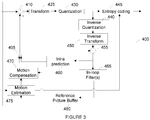
- Figure 3 illustrates an exemplary video encoder 400 adapted to execute the encoding method of figure 4 .
- the encoder 400 is an example of a transmitter 200 or may be part of such a transmitter 200.
- a picture may be partitioned into coding tree units (CTU) of square shape with a configurable size.
- CTU coding tree units
- a consecutive set of coding tree units may be grouped into a slice.
- a CTU is the root of a tree partitioning into Coding Units.
- an image is partitioned into one or more slices where each slice can include one or more slice segments.
- a slice segment is organized into coding units, prediction units and transform units.
- the HEVC specification distinguishes between “blocks” and “units,” where a "block” addresses a specific area in a sample array (e.g., luma, Y), and the “unit” includes the collocated block of all encoded color components (Y, Cb, Cr, or monochrome), syntax elements and prediction data that are associated with the block (e.g., motion vectors).
- a "block” addresses a specific area in a sample array (e.g., luma, Y)
- the “unit” includes the collocated block of all encoded color components (Y, Cb, Cr, or monochrome), syntax elements and prediction data that are associated with the block (e.g., motion vectors).
- an image is partitioned into basic coding blocks, e.g. into coding tree blocks (CTB) of square shape with a configurable size in HEVC or into macroblocks in H.264, and a set of possibly consecutive basic coding blocks is grouped into a slice.
- CTB
- the basic coding units are of square shape of 2 n x2 n samples, where n is an integer, e.g. n ⁇ ⁇ 4, 5, 6 ⁇ .
- n is an integer, e.g. n ⁇ ⁇ 4, 5, 6 ⁇ .
- the smallest CTU size 16x16 corresponds to a macroblock size as used in previous video coding standards.
- CTU and CTB are used herein to describe encoding/decoding methods and encoding/decoding apparatus, these methods and apparatus should not be limited by these specific terms that may be worded differently (e.g. macroblock) in other standards such as H.264 or H.266.
- a Coding Tree Unit (CTU) corresponding to a CTB contains the CTBs of the encoded color components.
- a basic coding unit corresponding to a basic coding block contains the basic coding blocks of the encoded color components.
- a CTB is the root of a quadtree partitioning into Coding Blocks (CB), and a Coding Block is partitioned into one or more Prediction Blocks (PB) and forms the root of a quadtree partitioning into Transform Blocks (TBs).
- a Coding Unit includes the Prediction Units (PUs) and the tree-structured set of Transform Units (TUs), a PU includes the prediction information for all color components, and a TU includes residual coding syntax structure for each color component.
- the size of a CB, PB and TB of the luma component applies to the corresponding CU, PU and TU.
- the term "block” can be used to refer to any of CTU, CU, PU, TU, CB, PB and TB.
- the "block” can be used to refer to a macroblock, a partition and a sub-block as specified in H.264/AVC or other video coding standards, and more generally to refer to an array of samples of various sizes.
- a picture is encoded by the encoder modules as described below.
- Each block is encoded using either an intra or inter mode.
- the encoder 400 performs intra prediction (module 460).
- an inter mode motion estimation (module 475) and compensation (module 470) are performed.
- the encoder decides (module 405) which one of the intra mode or inter mode to use for encoding the block, and indicates the intra/inter decision by a prediction mode flag. Residuals are calculated by subtracting (module 410) a block of prediction samples (also known as a predictor) from the original image block.
- blocks in intra mode are predicted from reconstructed neighboring samples.
- Inter prediction is performed by motion-compensating a reference block stored in a reference picture buffer 480.
- the residuals are transformed (module 425) and quantized (module 430).
- the quantized transform coefficients, as well as motion vectors and other syntax elements, are entropy coded (module 445) to output a bitstream.
- the encoder may also skip the transform and apply quantization directly to the non-transformed residual signal.
- the encoder may also bypass both transform and quantization, i.e., the residual is coded directly without the application of the transform or quantization process. In direct PCM coding, no prediction is applied and the block samples are directly coded into the bitstream.
- the quantized transform coefficients are de-quantized (module 440) and inverse transformed (module 450) to decode residuals.
- An image block is reconstructed by combining (module 455) the decoded residuals and the block of prediction samples.
- An in-loop filter (465) may be applied to the reconstructed picture, for example, to perform deblocking/SAO (Sample Adaptive Offset) filtering to reduce coding artifacts.
- the filtered image is stored in the reference picture buffer 480.
- the transform and quantization are implemented in a fixed point way.
- HEVC High Efficiency Video Coding
- the quantization is implemented by multiplying the transform coefficients by 2 14 and then dividing them by Qstep and de-quantization by multiplying the quantized transform coefficients by 2 6 and Qstep.
- a quantization parameter QP
- QP can take 52 values from 0 to 51.
- An increase of 1 in QP means an increase of the quantization step size by approximately 12% (i.e., 2 1/6 ).
- An increase of 6 leads to an increase in the quantization step size by a factor of 2.
- QP the quantization parameter
- coeff the transform coefficient
- level the resulting quantized transform coefficient
- offset Q the offset used for appropriate rounding in the division by Q step
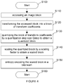
- Figure 4 represents a flowchart of a method for encoding an image in a bitstream according to a specific and non-limiting embodiment.
- an image block is an array of luma or chroma samples, or an array of residuals.
- a block of residuals may be obtained by subtracting a predictor, i.e. an array of prediction samples, from a block of luma or chroma samples.
- the transmitter transforms the accessed block into a block of transform coefficients, e.g. a block of DCT coefficients in the case where the transform is a DCT transform (Discrete Cosine Transform). It will be appreciated, however, that the present principles are not restricted to this specific transform.
- a DCT transform Discrete Cosine Transform
- the transmitter quantizes the block of transform coefficients by a quantization step size Qstep to obtain a quantized block.
- quantization comprises dividing the transform coefficients by the quantization step size Qstep.
- the transform and quantization are implemented in a fixed point way. These operations may require some scaling steps.
- the transmitter scales the quantized block, i.e. the block of quantized transform coefficients, by a scaling factor S Q to obtain a scaled block.
- Scaling a block includes scaling each coefficient of the block.
- the value of the scaling factor depends on whether at least one of the width and the height of the block is equal to a power of 2, i.e. is equal to 2 n , where n is an integer.
- the scaling factor S Q according to the present principles is thus adapted to scale a block whose width and/or height is not a power of 2, e.g. is equal to 3x2 n , n being an integer.
- the scaling factor S Q is defined to ensure that the norm of a corresponding residual block is preserved between the spatial domain and the transform domain.
- the scaling factor S Q is equal to : s 1 s 1 * ⁇ s 1 * s 2 ⁇ 2 ⁇ 15 ⁇ B ⁇ 1 f 4
- S Q s 1 s 1 * ⁇ s 1 * s 2 ⁇ 2 ⁇ 15 + f ⁇ B
- S Q s 1 s 1 * ⁇ s 1 * s 2 ⁇ 2 ⁇ 29 ⁇ B
- B is the bitdepth of the image block
- s1 is the width and s2 the height of the block or vice versa
- s 1 * is the smallest integer equal to a power of 2 that is greater than s1.
- the scaling factor S Q is proportional to 3 4 ⁇ s 1 * s 2 .
- S Q s 1 s 1 * ⁇ s 2 s 2 * ⁇ s 1 * s 2 * ⁇ 2 ⁇ 15 + f ⁇ B ⁇ 1 f 4
- S Q s 1 s 1 * ⁇ s 2 s 2 * ⁇ s 1 * s 2 * ⁇ 2 ⁇ 15 + f ⁇ B ⁇ 1 f 4
- S Q s 1 s 1 * ⁇ s 2 s 2 * ⁇ s 1 * s 2 * ⁇ 2 ⁇ 29 ⁇ B
- s 1 * is the smallest integer equal to a power of 2 that is greater than s1
- s 2 * is the smallest integer equal to a power of 2 that is greater than s2.
- the scaling S Q factor is proportional to 3 4 ⁇ s 1 * s 2 .
- S Q 3 4 ⁇ s 1 * s 2 * ⁇ 2 ⁇ 29 ⁇ B
- the transmitter encodes the scaled block in a bitstream by entropy coding, e.g. CABAC or CALVC. It will be appreciated, however, that the present principles are not restricted to these specific entropy coding processes.
- Steps S110 to S150 may be iterated to encode all the blocks of an image.
- the method ends at step S180.
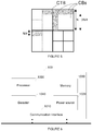
- the encoding method according to the present principles is advantageously applied on coding block split into asymmetric sub-blocks as depicted on figure 5 .
- a CTB is split into asymmetric CBs.
- a coding block may be split horizontally into one sub-block of height h/4 and one sub-block of height 3h/4.
- the sub-block of height h/4 is either above or below the sub-block of height 3h/4.
- the coding block may be split vertically into one sub-block of width w/4 and one sub-block of width 3w/4.
- the sub-block of width w/4 is either on the left or right of the sub-block of width 3w/4.
- the coding block is split either horizontally or vertically into sub-blocks whose size is not a power of two, e.g. their size in width w or height h is equal to 3x2 n pixels with n being an integer.
- Figure 6 represents an exemplary architecture of a receiver 100 configured to decode an image block from a bitstream to obtain a decoded image block according to a non-limiting embodiment.
- the receiver 100 comprises one or more processor(s) 1000, which could comprise, for example, a CPU, a GPU and/or a DSP (English acronym of Digital Signal Processor), along with internal memory 1030 (e.g. RAM, ROM and/or EPROM).
- the receiver 100 comprises one or more communication interface(s) 1010 (e.g. a keyboard, a mouse, a touchpad, a webcam), each adapted to display output information and/or allow a user to enter commands and/or data (e.g. the decoded image block); and a power source 1020 which may be external to the receiver 100.
- the receiver 100 may also comprise one or more network interface(s) (not shown).
- the decoder module 1040 represents the module that may be included in a device to perform the decoding functions. Additionally, the decoder module 1040 may be implemented as a separate element of the receiver 100 or may be incorporated within processor(s) 1000 as a combination of hardware and software as known to those skilled in the art.
- the bitstream may be obtained from a source.
- the source can be, but is not limited to:
- Figure 7 illustrates a block diagram of an exemplary video decoder 300 adapted to execute the decoding method of figure 8 .
- the video decoder 300 is an example of a receiver 100 or part of such a receiver 100.
- a bitstream is decoded by the decoder elements as described below.
- Video decoder 300 generally performs a decoding pass reciprocal to the encoding pass as described in Figure 3 , which performs video decoding as part of encoding video data.
- the input of the decoder includes a video bitstream, which may be generated by the video encoder 400.
- the bitstream is first entropy decoded (330) to obtain transform coefficients, motion vectors, and other coded information.
- the transform coefficients are de-quantized (340) and inverse transformed (350) which provides decoded residuals.
- the decoded residuals are then combined (355) with a block of prediction samples (also known as a predictor) to obtain a decoded/reconstructed image block.
- the block of prediction samples may be obtained (370) from intra prediction (360) or motion-compensated prediction (i.e., inter prediction) (375).
- AMVP and merge mode techniques may be used during motion compensation, which may use interpolation filters to calculate interpolated values for sub-integer samples of a reference block.
- An in-loop filter (365) may be applied to the reconstructed image.
- the in-loop filter may comprise a deblocking filter and a SAO filter.
- the filtered image is stored at a reference picture buffer (380).
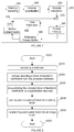
- Figure 8 represents a flowchart of a method for decoding an image block from a bitstream according to a specific and non-limiting embodiment.
- the method starts at step S200.
- a receiver 100 such as the decoder 300 accesses a bitstream.
- the receiver decodes at least one block of transform coefficients from the bitstream by entropy decoding.
- the transmitter de-quantizes the decoded block of transform coefficients by a quantization step size Qstep to obtain a de-quantized block.
- de-quantization comprises multiplying the transform coefficients by the quantization step size Qstep.
- the transform and quantization are implemented in a fixed point way. These operations may thus comprise some scaling steps.
- the de-quantization is implemented by multiplying the transform coefficients by 2 6 and by Qstep.
- the transmitter scales the de-quantized block by a scaling factor S IQ to obtain a scaled block.
- Scaling a block includes scaling each coefficient of the block.
- the value of the scaling factor S IQ depends on whether at least one of the width and the height of the block to be scaled is equal to a power of 2, i.e. is equal or not to 2 n , where n is an integer.
- the scaling factor S IQ according to the present principles is thus adapted to scale a block whose width and/or height is not a power of 2, e.g. is equal to 3x2 n , n being an integer.
- the scaling factor S IQ is equal to s 1 * s 1 ⁇ 1 s 1 * s 2 ⁇ 2 ⁇ B ⁇ 15 ⁇ 1 g 4
- S IQ s 1 * s 1 ⁇ 1 s 1 * s 2 ⁇ 2 ⁇ 15 + g ⁇ B
- S IQ s 1 * s 1 ⁇ 1 s 1 * s 2 ⁇ 2 ⁇ B ⁇ 9
- B is the bitdepth of the image block
- s1 is the width and s2 the height of the block or vice versa
- s 1 * is the smallest integer equal to a power of 2 that is greater than s1.
- the scaling S IQ factor is proportional to 4 3 ⁇ 1 s 1 * s 2 .
- S IQ s 1 * s 1 ⁇ s 2 * s 2 ⁇ 1 s 1 * s 2 * ⁇ 2 ⁇ B ⁇ 15 + g
- S IQ s 1 * s 1 ⁇ s 2 * s 2 ⁇ 1 s 1 * s 2 * ⁇ 2 ⁇ B ⁇ 9
- s 1 * is the smallest integer equal to a power of 2 that is greater than s1 and s 2 * is the smallest integer equal to a power of 2 that is greater than s2.
- the scaling factor S IQ is proportional to 4 3 ⁇ 1 s 1 * s 2 * .
- the transmitter transforms the scaled block into an image block, i.e. a block of luma or chroma samples, or a block of residuals.
- a block of luma or chroma samples may be obtained by adding a predictor, i.e. an array of prediction samples, to a block of residuals.
- the transform may be an IDCT transform (Inverse Discrete Cosine Transform).
- the transform of step S250 is the inverse transform applied on the encoder side at step S120.
- the transform used is an inverse transform of the transform used at step S120 of the encoding method.
- Steps S210 to S250 may be iterated to encode all the blocks of an image.
- the method ends at step S280.
- the implementations described herein may be implemented in, for example, a method or a process, an apparatus, a software program, a data stream, or a signal. Even if only discussed in the context of a single form of implementation (for example, discussed only as a method or a device), the implementation of features discussed may also be implemented in other forms (for example a program).
- An apparatus may be implemented in, for example, appropriate hardware, software, and firmware.
- the methods may be implemented in, for example, an apparatus such as, for example, a processor, which refers to processing devices in general, including, for example, a computer, a microprocessor, an integrated circuit, or a programmable logic device. Processors also include communication devices, such as, for example, computers, cell phones, portable/personal digital assistants ("PDAs”), and other devices that facilitate communication of information between end-users.
- PDAs portable/personal digital assistants
- Implementations of the various processes and features described herein may be embodied in a variety of different equipment or applications, particularly, for example, equipment or applications.
- equipment examples include an encoder, a decoder, a post-processor processing output from a decoder, a pre-processor providing input to an encoder, a video coder, a video decoder, a video codec, a web server, a set-top box, a laptop, a personal computer, a cell phone, a PDA, and other communication devices.
- the equipment may be mobile and even installed in a mobile vehicle.
- the methods may be implemented by instructions being performed by a processor, and such instructions (and/or data values produced by an implementation) may be stored on a processor-readable medium such as, for example, an integrated circuit, a software carrier or other storage device such as, for example, a hard disk, a compact diskette (“CD"), an optical disc (such as, for example, a DVD, often referred to as a digital versatile disc or a digital video disc), a random access memory (“RAM”), or a read-only memory (“ROM”).
- the instructions may form an application program tangibly embodied on a processor-readable medium. Instructions may be, for example, in hardware, firmware, software, or a combination.
- a processor may be characterized, therefore, as, for example, both a device configured to carry out a process and a device that includes a processor-readable medium (such as a storage device) having instructions for carrying out a process. Further, a processor-readable medium may store, in addition to or in lieu of instructions, data values produced by an implementation.
- implementations may produce a variety of signals formatted to carry information that may be, for example, stored or transmitted.
- the information may include, for example, instructions for performing a method, or data produced by one of the described implementations.
- a signal may be formatted to carry as data the rules for writing or reading the syntax of a described embodiment, or to carry as data the actual syntax-values written by a described embodiment.
- Such a signal may be formatted, for example, as an electromagnetic wave (for example, using a radio frequency portion of spectrum) or as a baseband signal.
- the formatting may include, for example, encoding a data stream and modulating a carrier with the encoded data stream.
- the information that the signal carries may be, for example, analog or digital information.
- the signal may be transmitted over a variety of different wired or wireless links, as is known.
- the signal may be stored on a processor-readable medium.
Landscapes
- Engineering & Computer Science (AREA)
- Multimedia (AREA)
- Signal Processing (AREA)
- Compression Or Coding Systems Of Tv Signals (AREA)
Abstract
A decoding method is disclosed that comprises:
- decoding a block of transform coefficients from a bitstream;
- de-quantizing the decoded block of transform coefficients by a quantization step size;
- scaling said dequantized block by a scaling factor; and
- transforming said scaled block into an image block,
wherein the scaling factor's value depends on whether at least one of the width and the height of the block is a power of 2.
- decoding a block of transform coefficients from a bitstream;
- de-quantizing the decoded block of transform coefficients by a quantization step size;
- scaling said dequantized block by a scaling factor; and
- transforming said scaled block into an image block,
wherein the scaling factor's value depends on whether at least one of the width and the height of the block is a power of 2.
Description
- The present principles generally relate to a method and a device for image encoding and decoding, and more particularly, to a method and a device for image encoding and decoding with quantizing and inverse quantizing.
- To achieve high compression efficiency, video coding schemes usually employ prediction and transform to leverage spatial and temporal redundancy in the video content. Generally, intra or inter prediction is used to exploit the intra or inter frame correlation, then the differences between group of samples in the original image and in the prediction image, often denoted as residuals, are transformed, quantized and entropy coded. To reconstruct the video, the compressed data is decoded by inverse processes corresponding to the prediction, transform, quantization and entropy coding.
- In HEVC coding ("ITU-T H.265 Telecommunication standardization sector of ITU (4/2015), series H: audiovisual and multimedia systems, infrastructure of audiovisual services - coding of moving video, High efficiency video coding, Recommendation ITU-T H.265"), transform and quantization are applied on square blocks whose size in each dimension is equal to a power of 2, i.e. of size 2 M ×2 M . As depicted on
figure 1 , quantization comprises quantization by Qstep (S10) followed by scaling (S12) by a scaling factor SQ equal to 2-(29-M-B) where B is the bitdepth of the original image. In an analogous way, de-quantization comprises de-quantization by Qstep followed by scaling by a scale factor SIQ equal to SIQ = 2 -(M+B-9). - The HEVC quantization and scaling are only adapted to square blocks whose width and/or height are/is a power of 2.
- A decoding method is disclosed that comprises:
- decoding a block of transform coefficients from a bitstream;
- de-quantizing the decoded block of transform coefficients by a quantization step size to obtain a dequantized block;
- scaling the dequantized block by a scaling factor to obtain a scaled block; and
- transforming the scaled block into an image block,
- A decoding device is disclosed that comprises:
- means for decoding a block of transform coefficients from a bitstream;
- means for de-quantizing the decoded block of transform coefficients by a quantization step size to obtain a dequantized block;
- means for scaling the dequantized block by a scaling factor to obtain a scaled block; and
- means for transforming the scaled block into an image block,
- A decoding device comprising a communication interface and at least one processor is disclosed. The communication interface is configured to access at least a bitstream and the at least one processor is configured to:
- decode a block of transform coefficients from the accessed bitstream;
- de-quantizing the decoded block of transform coefficients by a quantization step size to obtain a dequantized block;
- scaling the dequantized block by a scaling factor to obtain a scaled block; and
- transforming the scaled block into an image block,
- The following embodiments apply to the decoding method and decoding devices disclosed above.
- In a first embodiment, wherein s1 is not a power of 2 and s2 is a power of 2, the scaling factor SIQ is proportional to

- Advantageously, when s1 is not a power of 2 and s2 is a power of 2, the scaling factor SIQ is substantially equal to
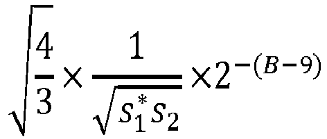
- Advantageously, in the specific case where s 1 = 3×2 n1 and s 2 = 2 n2, the scaling factor SIQ is substantially equal to

and otherwise, the scaling factor SIQ is substantially equal to
- In a second embodiment, wherein neither s1 nor s2 is a power of 2, the scaling factor SIQ is proportional to

- Advantageously, when neither s1 nor s2 is a power of 2, the scaling factor SIQ is substantially equal to

- Advantageously, in the specific case where s 1 = 3×2 n1 and s 2 = 3×2 n2, the scaling factor SIQ is substantially equal to


- A coding is also disclosed that comprises:
- transforming an image block into a block of transform coefficients;
- quantizing the block of transform coefficients by a quantization step size to obtain a quantized block; and
- scaling the quantized block by a scaling factor to obtain a scaled block;
- encoding the scaled block into a bitstream;
- A coding device is also disclosed that comprises:
- means for transforming an image block into a block of transform coefficients;
- means for quantizing the block of transform coefficients by a quantization step size to obtain a quantized block; and
- means for scaling the quantized block by a scaling factor to obtain a scaled block;
- means for encoding the scaled block into a bitstream;
- A coding device comprising a communication interface and at least one processor is disclosed. The communication interface is configured to access an image block and the at least one processor is configured to:
- transform the accessed image block into a block of transform coefficients;
- quantize the block of transform coefficients by a quantization step size to obtain a quantized block; and
- scale the quantized block by a scaling factor to obtain a scaled block;
- encode the scaled block into a bitstream;
- The following embodiments apply to the coding method and coding devices disclosed above.
- In a first embodiment, wherein s1 is not a power of 2 and s2 is a power of 2, the scaling factor SQ is proportional to

- Advantageously, when s1 is not a power of 2 and s2 is a power of 2, the scaling factor SQ is substantially equal to

- Advantageously, in the specific case where s 1 = 3×2 n1 and s 2 = 2 n2, the scaling factor SQ is substantially equal to

and otherwise, the scaling factor SQ is substantially equal to
- In a second embodiment, in the case where neither s1 nor s2 is a power of 2, said scaling factor SQ is proportional to

- Advantageously, when neither s1 nor s2 is a power of 2, the scaling factor SQ is substantially equal to

- Advantageously, in the specific case where s 1 = 3×2 n1 and s 2 = 3×2 n2 the scaling factor SQ is substantially equal to


-
-
Figure 1 represents a flowchart of quantization and scaling of transform coefficients according to the prior art; -
Figure 2 represents an exemplary architecture of a transmitter configured to encode an image block in a bitstream according to a specific and non-limiting embodiment; -
Figure 3 illustrates an exemplary video encoder adapted to execute the encoding method according to the present principles; -
Figure 4 represents a flowchart of a method for encoding an image in a bitstream according to a specific and non-limiting embodiment; -
Figure 5 depicts an example of a partitioning of a CTB into asymmetric CBs according to the present principles; -
Figure 6 represents an exemplary architecture of a receiver configured to decode an image block from a bitstream according to a specific and non-limiting embodiment; -
Figure 7 illustrates a block diagram of an exemplary video decoder adapted to execute the decoding method according to the present principles; and -
Figure 8 represents a flowchart of a method for decoding an image block from a bitstream according to a specific and non-limiting embodiment. - It is to be understood that the figures and descriptions have been simplified to illustrate elements that are relevant for a clear understanding of the present principles, while eliminating, for purposes of clarity, many other elements found in typical encoding and/or decoding devices. It will be understood that, although the terms first and second may be used herein to describe various elements, these elements should not be limited by these terms. These terms are only used to distinguish one element from another. Various methods are described above, and each of the methods comprises one or more steps or actions for achieving the described method. Unless a specific order of steps or actions is required for proper operation of the method, the order and/or use of specific steps and/or actions may be modified or combined.
- A picture is an array of luma samples in monochrome format or an array of luma samples and two corresponding arrays of chroma samples in 4:2:0, 4:2:2, and 4:4:4 colour format. Generally, a "block" addresses a specific area in a sample array (e.g., luma Y), and a "unit" includes the collocated block of all encoded color components (luma Y and possibly chroma Cb and chroma Cr). However, the term "block" or "image block" is used herein to refer to a block (e.g. a coding block or CB) or a unit (e.g. a coding unit or CU). In the present principles, a block may also refer to an array of residuals.
- In the following, the word "reconstructed" and "decoded" can be used interchangeably. Usually but not necessarily "reconstructed" is used on the encoder side while "decoded" is used on the decoder side.
- Various embodiments are described with respect to the HEVC standard. However, the present principles are not limited to HEVC, and can be applied to other standards, recommendations, and extensions thereof, including for example HEVC or HEVC extensions like Format Range (RExt), Scalability (SHVC), and Multi-View (MV-HEVC) Extensions. The various embodiments are described with respect to the encoding/decoding of an image block. They may be applied to encode/decode a whole picture or a whole sequence of images.
-
Figure 2 represents an exemplary architecture of atransmitter 200 configured to encode an image block in a bitstream according to a specific and non-limiting embodiment. - The
transmitter 200 comprises one or more processor(s) 2000, which could comprise, for example, a CPU, a GPU and/or a DSP (English acronym of Digital Signal Processor), along with internal memory 2030 (e.g. RAM, ROM, and/or EPROM). Thetransmitter 200 comprises one or more communication interface(s) 2010 (e.g. a keyboard, a mouse, a touchpad, a webcam), each adapted to display output information and/or allow a user to enter commands and/or data (e.g. a stream); and apower source 2020 which may be external to thetransmitter 200. Thetransmitter 200 may also comprise one or more network interface(s) (not shown).Encoder module 2040 represents the module that may be included in a device to perform the coding functions. Additionally,encoder module 2040 may be implemented as a separate element of thetransmitter 200 or may be incorporated within processor(s) 2000 as a combination of hardware and software as known to those skilled in the art.
The image block may be obtained from a source. According to different embodiments, the source can be, but is not limited to: - a local memory, e.g. a video memory, a RAM, a flash memory, a hard disk ;
- a storage interface, e.g. an interface with a mass storage, a ROM, an optical disc or a magnetic support;
- a communication interface, e.g. a wireline interface (for example a bus interface, a wide area network interface, a local area network interface) or a wireless interface (such as a IEEE 802.11 interface or a Bluetooth interface); and
- an image capturing circuit (e.g. a sensor such as, for example, a CCD (or Charge-Coupled Device) or CMOS (or Complementary Metal-Oxide-Semiconductor)).
- a mobile device ;
- a communication device ;
- a game device ;
- a tablet (or tablet computer) ;
- a laptop ;
- a still image camera;
- a video camera ;
- an encoding chip or encoding device/apparatus;
- a still image server; and
- a video server (e.g. a broadcast server, a video-on-demand server or a web server).
-
Figure 3 illustrates anexemplary video encoder 400 adapted to execute the encoding method offigure 4 . Theencoder 400 is an example of atransmitter 200 or may be part of such atransmitter 200. - To encode a video sequence with one or more pictures, a picture may be partitioned into coding tree units (CTU) of square shape with a configurable size. A consecutive set of coding tree units may be grouped into a slice. A CTU is the root of a tree partitioning into Coding Units. To encode a video sequence with one or more images, an image is partitioned into one or more slices where each slice can include one or more slice segments. A slice segment is organized into coding units, prediction units and transform units. The HEVC specification distinguishes between "blocks" and "units," where a "block" addresses a specific area in a sample array (e.g., luma, Y), and the "unit" includes the collocated block of all encoded color components (Y, Cb, Cr, or monochrome), syntax elements and prediction data that are associated with the block (e.g., motion vectors).
For coding, an image is partitioned into basic coding blocks, e.g. into coding tree blocks (CTB) of square shape with a configurable size in HEVC or into macroblocks in H.264, and a set of possibly consecutive basic coding blocks is grouped into a slice. Usually, the basic coding units are of square shape of 2nx2n samples, where n is an integer, e.g. n ∈ {4, 5, 6}. In HEVC, the smallest CTU size 16x16 corresponds to a macroblock size as used in previous video coding standards. It will be understood that, although the terms CTU and CTB are used herein to describe encoding/decoding methods and encoding/decoding apparatus, these methods and apparatus should not be limited by these specific terms that may be worded differently (e.g. macroblock) in other standards such as H.264 or H.266. A Coding Tree Unit (CTU) corresponding to a CTB contains the CTBs of the encoded color components. More generally, a basic coding unit corresponding to a basic coding block contains the basic coding blocks of the encoded color components. A CTB is the root of a quadtree partitioning into Coding Blocks (CB), and a Coding Block is partitioned into one or more Prediction Blocks (PB) and forms the root of a quadtree partitioning into Transform Blocks (TBs). Corresponding to the Coding Block, Prediction Block and Transform Block, a Coding Unit (CU) includes the Prediction Units (PUs) and the tree-structured set of Transform Units (TUs), a PU includes the prediction information for all color components, and a TU includes residual coding syntax structure for each color component. The size of a CB, PB and TB of the luma component applies to the corresponding CU, PU and TU. In the present application, the term "block" can be used to refer to any of CTU, CU, PU, TU, CB, PB and TB. In addition, the "block" can be used to refer to a macroblock, a partition and a sub-block as specified in H.264/AVC or other video coding standards, and more generally to refer to an array of samples of various sizes. - In the
exemplary encoder 400, a picture is encoded by the encoder modules as described below. Each block is encoded using either an intra or inter mode. When a block is encoded in an intra mode, theencoder 400 performs intra prediction (module 460). In an inter mode, motion estimation (module 475) and compensation (module 470) are performed. The encoder decides (module 405) which one of the intra mode or inter mode to use for encoding the block, and indicates the intra/inter decision by a prediction mode flag. Residuals are calculated by subtracting (module 410) a block of prediction samples (also known as a predictor) from the original image block.
As an example, blocks in intra mode are predicted from reconstructed neighboring samples. Inter prediction is performed by motion-compensating a reference block stored in areference picture buffer 480.
The residuals are transformed (module 425) and quantized (module 430). The quantized transform coefficients, as well as motion vectors and other syntax elements, are entropy coded (module 445) to output a bitstream. The encoder may also skip the transform and apply quantization directly to the non-transformed residual signal. The encoder may also bypass both transform and quantization, i.e., the residual is coded directly without the application of the transform or quantization process. In direct PCM coding, no prediction is applied and the block samples are directly coded into the bitstream.
The encoder comprises a decoding loop and thus decodes an encoded block of size NxN with N= 2M and M is an integer to provide a reference for further predictions. The quantized transform coefficients are de-quantized (module 440) and inverse transformed (module 450) to decode residuals. An image block is reconstructed by combining (module 455) the decoded residuals and the block of prediction samples. An in-loop filter (465) may be applied to the reconstructed picture, for example, to perform deblocking/SAO (Sample Adaptive Offset) filtering to reduce coding artifacts. The filtered image is stored in thereference picture buffer 480.
Usually, the transform and quantization are implemented in a fixed point way. These operations may thus comprise some scaling steps. In HEVC, the quantization is implemented by multiplying the transform coefficients by 214 and then dividing them by Qstep and de-quantization by multiplying the quantized transform coefficients by 26 and Qstep. More precisely, in HEVC, a quantization parameter (QP) is used to determine the quantization step size Qstep. QP can take 52 values from 0 to 51. An increase of 1 in QP means an increase of the quantization step size by approximately 12% (i.e., 21/6). An increase of 6 leads to an increase in the quantization step size by a factor of 2. In addition to specifying the relative difference between the step-sizes of two consecutive QP values, there is a need to define the absolute step-size associated with the range of QP values. This is done by selecting Qstep = 1 for QP=4. The resulting relationship between QP and the equivalent quantization step size is given by the following equations:

HEVC quantization and de-quantization are basically fixed point approximation of the latter equation. Additional scale factors SQ and SIQ are thus used to restore the norm of the residual block which gets modified because of the scaling used in fixed point implementation. In HEVC, the fixed point approximation of the latter equation is given by g QP%6 = round(26×G QP%6), which results in g= [g0, ...., g5]T=[40, 45, 51, 57, 64, 72]T
The de-quantization in HEVC is expressed as follows:
The quantization in HEVC is expressed as follows:
-
Figure 4 represents a flowchart of a method for encoding an image in a bitstream according to a specific and non-limiting embodiment. - The method starts at step S100. At step S110, a transmitter, e.g. such as the
encoder 400, accesses an image block. According to the present principles, an image block is an array of luma or chroma samples, or an array of residuals. A block of residuals may be obtained by subtracting a predictor, i.e. an array of prediction samples, from a block of luma or chroma samples. - At step S120, the transmitter transforms the accessed block into a block of transform coefficients, e.g. a block of DCT coefficients in the case where the transform is a DCT transform (Discrete Cosine Transform). It will be appreciated, however, that the present principles are not restricted to this specific transform.
- At step S130, the transmitter quantizes the block of transform coefficients by a quantization step size Qstep to obtain a quantized block. Conceptually, quantization comprises dividing the transform coefficients by the quantization step size Qstep. Usually, the transform and quantization are implemented in a fixed point way. These operations may require some scaling steps.
- At step S140, the transmitter scales the quantized block, i.e. the block of quantized transform coefficients, by a scaling factor SQ to obtain a scaled block. Scaling a block includes scaling each coefficient of the block. According to the present principles the value of the scaling factor depends on whether at least one of the width and the height of the block is equal to a power of 2, i.e. is equal to 2n, where n is an integer. The scaling factor SQ according to the present principles is thus adapted to scale a block whose width and/or height is not a power of 2, e.g. is equal to 3x2n, n being an integer. The scaling factor SQ is defined to ensure that the norm of a corresponding residual block is preserved between the spatial domain and the transform domain.
- According to the present principles, "equal to" is to be understood as "substantially equal to" since the scaling factor's value may be determined using fixed-point number in which case rounding errors may occur.
- In a first embodiment in which s1 is not a power of 2 and s2 is a power of 2, the scaling factor SQ is equal to :


- In the specific case where s 1 = 3×2 n1 and s 2 = 2 n2, the scaling factor SQ is proportional to

- More precisely, for f=14,
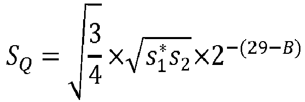

- This leads to two sub-cases depending on whether n 1 + 2 + n 2 is a multiple of 2.
- In the case where (n 1 + 2 + n 2)%2 = 0, where % is the operator modulo,


- In a second embodiment in which neither s1 nor s2 is a power of 2, the scaling factor is equal to


- In the specific case where s 1 = 3×2 n1 and s 2 = 3×2 n2, the scaling SQ factor is proportional to


- This leads to two sub-cases depending on whether n 1 + 2 + n 2 + 2 is a multiple of 2.
- In the case where (n 1 + n 2 + 4)%2 = 0, where % is the operator modulo,


- At step S150, the transmitter encodes the scaled block in a bitstream by entropy coding, e.g. CABAC or CALVC. It will be appreciated, however, that the present principles are not restricted to these specific entropy coding processes.
- Steps S110 to S150 may be iterated to encode all the blocks of an image. The method ends at step S180.
The encoding method according to the present principles is advantageously applied on coding block split into asymmetric sub-blocks as depicted onfigure 5 . On this figure, a CTB is split into asymmetric CBs. As an example, a coding block may be split horizontally into one sub-block of height h/4 and one sub-block of height 3h/4. The sub-block of height h/4 is either above or below the sub-block of height 3h/4. In another embodiment, the coding block may be split vertically into one sub-block of width w/4 and one sub-block of width 3w/4. The sub-block of width w/4 is either on the left or right of the sub-block of width 3w/4. In a specific embodiment, the coding block is split either horizontally or vertically into sub-blocks whose size is not a power of two, e.g. their size in width w or height h is equal to 3x2n pixels with n being an integer. -
Figure 6 represents an exemplary architecture of areceiver 100 configured to decode an image block from a bitstream to obtain a decoded image block according to a non-limiting embodiment. - The
receiver 100 comprises one or more processor(s) 1000, which could comprise, for example, a CPU, a GPU and/or a DSP (English acronym of Digital Signal Processor), along with internal memory 1030 (e.g. RAM, ROM and/or EPROM). Thereceiver 100 comprises one or more communication interface(s) 1010 (e.g. a keyboard, a mouse, a touchpad, a webcam), each adapted to display output information and/or allow a user to enter commands and/or data (e.g. the decoded image block); and apower source 1020 which may be external to thereceiver 100. Thereceiver 100 may also comprise one or more network interface(s) (not shown). Thedecoder module 1040 represents the module that may be included in a device to perform the decoding functions. Additionally, thedecoder module 1040 may be implemented as a separate element of thereceiver 100 or may be incorporated within processor(s) 1000 as a combination of hardware and software as known to those skilled in the art. - The bitstream may be obtained from a source. According to different embodiments, the source can be, but is not limited to:
- a local memory, e.g. a video memory, a RAM, a flash memory, a hard disk ;
- a storage interface, e.g. an interface with a mass storage, a ROM, an optical disc or a magnetic support;
- a communication interface, e.g. a wireline interface (for example a bus interface, a wide area network interface, a local area network interface) or a wireless interface (such as a IEEE 802.11 interface or a Bluetooth interface); and
- a picture capturing circuit (e.g. a sensor such as, for example, a CCD (or Charge-Coupled Device) or CMOS (or Complementary Metal-Oxide-Semiconductor)).
- a mobile device ;
- a communication device ;
- a game device ;
- a set top box;
- a TV set;
- a tablet (or tablet computer) ;
- a laptop ;
- a video player, e.g. a Blu-ray player, a DVD player;
- a display and
- a decoding chip or decoding device/apparatus.
-
Figure 7 illustrates a block diagram of anexemplary video decoder 300 adapted to execute the decoding method offigure 8 . Thevideo decoder 300 is an example of areceiver 100 or part of such areceiver 100. In theexemplary decoder 300, a bitstream is decoded by the decoder elements as described below.Video decoder 300 generally performs a decoding pass reciprocal to the encoding pass as described inFigure 3 , which performs video decoding as part of encoding video data.
In particular, the input of the decoder includes a video bitstream, which may be generated by thevideo encoder 400. The bitstream is first entropy decoded (330) to obtain transform coefficients, motion vectors, and other coded information. The transform coefficients are de-quantized (340) and inverse transformed (350) which provides decoded residuals. The decoded residuals are then combined (355) with a block of prediction samples (also known as a predictor) to obtain a decoded/reconstructed image block. The block of prediction samples may be obtained (370) from intra prediction (360) or motion-compensated prediction (i.e., inter prediction) (375). As described above, AMVP and merge mode techniques may be used during motion compensation, which may use interpolation filters to calculate interpolated values for sub-integer samples of a reference block. An in-loop filter (365) may be applied to the reconstructed image. The in-loop filter may comprise a deblocking filter and a SAO filter. The filtered image is stored at a reference picture buffer (380). -
Figure 8 represents a flowchart of a method for decoding an image block from a bitstream according to a specific and non-limiting embodiment. - The method starts at step S200. At step S210, a
receiver 100 such as thedecoder 300 accesses a bitstream. At step S220, the receiver decodes at least one block of transform coefficients from the bitstream by entropy decoding. - At step S230, the transmitter de-quantizes the decoded block of transform coefficients by a quantization step size Qstep to obtain a de-quantized block. Conceptually, de-quantization comprises multiplying the transform coefficients by the quantization step size Qstep. Usually, the transform and quantization are implemented in a fixed point way. These operations may thus comprise some scaling steps. In HEVC, the de-quantization is implemented by multiplying the transform coefficients by 26 and by Qstep.
- At step S240, the transmitter scales the de-quantized block by a scaling factor SIQ to obtain a scaled block. Scaling a block includes scaling each coefficient of the block.
According to the present principles the value of the scaling factor SIQ depends on whether at least one of the width and the height of the block to be scaled is equal to a power of 2, i.e. is equal or not to 2n, where n is an integer. The scaling factor SIQ according to the present principles is thus adapted to scale a block whose width and/or height is not a power of 2, e.g. is equal to 3x2n, n being an integer. - According to the present principles, "equal to" is to be understood as "substantially equal to" since the scaling factor's value may be determined using fixed-point number in which case rounding errors may occur.
- In a first embodiment where s1 is not a power of 2 and s2 is a power of 2, the scaling factor SIQ is equal to

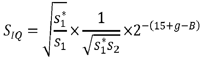

- In the specific case where s 1 = 3×2 n1 and s 2 = 2 n2, the scaling SIQ factor is proportional to

- In the specific case where g=6, i.e. g4=64,


- This leads to two sub-cases depending on whether n 1 + 2 + n 2 is a multiple of 2.
- In the case where (n 1 + 2 + n 2)%2 = 0, where % is the operator modulo, the scaling factor is equal to


- In a second embodiment where neither s1 nor s2 is a power of 2, the scaling factor is equal to


- In the specific case where s 1 = 3×2 n1 and s 2 = 3×2 n2, the scaling factor SIQ is proportional to

- In the specific case where g=6,


- In the case where (n 1 + n 2 + 4)%2 = 0, where % is the operator modulo,


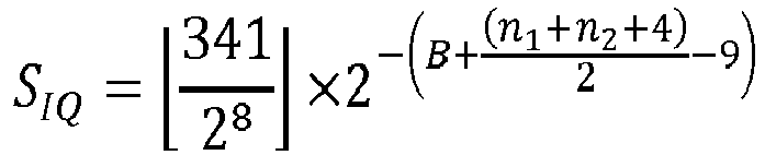

- At step S250, the transmitter transforms the scaled block into an image block, i.e. a block of luma or chroma samples, or a block of residuals. A block of luma or chroma samples may be obtained by adding a predictor, i.e. an array of prediction samples, to a block of residuals. The transform may be an IDCT transform (Inverse Discrete Cosine Transform). The transform of step S250 is the inverse transform applied on the encoder side at step S120.
- The transform used is an inverse transform of the transform used at step S120 of the encoding method. Steps S210 to S250 may be iterated to encode all the blocks of an image.
The method ends at step S280. - The implementations described herein may be implemented in, for example, a method or a process, an apparatus, a software program, a data stream, or a signal. Even if only discussed in the context of a single form of implementation (for example, discussed only as a method or a device), the implementation of features discussed may also be implemented in other forms (for example a program). An apparatus may be implemented in, for example, appropriate hardware, software, and firmware. The methods may be implemented in, for example, an apparatus such as, for example, a processor, which refers to processing devices in general, including, for example, a computer, a microprocessor, an integrated circuit, or a programmable logic device. Processors also include communication devices, such as, for example, computers, cell phones, portable/personal digital assistants ("PDAs"), and other devices that facilitate communication of information between end-users.
- Implementations of the various processes and features described herein may be embodied in a variety of different equipment or applications, particularly, for example, equipment or applications. Examples of such equipment include an encoder, a decoder, a post-processor processing output from a decoder, a pre-processor providing input to an encoder, a video coder, a video decoder, a video codec, a web server, a set-top box, a laptop, a personal computer, a cell phone, a PDA, and other communication devices. As should be clear, the equipment may be mobile and even installed in a mobile vehicle.
- Additionally, the methods may be implemented by instructions being performed by a processor, and such instructions (and/or data values produced by an implementation) may be stored on a processor-readable medium such as, for example, an integrated circuit, a software carrier or other storage device such as, for example, a hard disk, a compact diskette ("CD"), an optical disc (such as, for example, a DVD, often referred to as a digital versatile disc or a digital video disc), a random access memory ("RAM"), or a read-only memory ("ROM"). The instructions may form an application program tangibly embodied on a processor-readable medium. Instructions may be, for example, in hardware, firmware, software, or a combination. Instructions may be found in, for example, an operating system, a separate application, or a combination of the two. A processor may be characterized, therefore, as, for example, both a device configured to carry out a process and a device that includes a processor-readable medium (such as a storage device) having instructions for carrying out a process. Further, a processor-readable medium may store, in addition to or in lieu of instructions, data values produced by an implementation.
- As will be evident to one of skill in the art, implementations may produce a variety of signals formatted to carry information that may be, for example, stored or transmitted. The information may include, for example, instructions for performing a method, or data produced by one of the described implementations. For example, a signal may be formatted to carry as data the rules for writing or reading the syntax of a described embodiment, or to carry as data the actual syntax-values written by a described embodiment. Such a signal may be formatted, for example, as an electromagnetic wave (for example, using a radio frequency portion of spectrum) or as a baseband signal. The formatting may include, for example, encoding a data stream and modulating a carrier with the encoded data stream. The information that the signal carries may be, for example, analog or digital information. The signal may be transmitted over a variety of different wired or wireless links, as is known. The signal may be stored on a processor-readable medium.
- A number of implementations have been described. Nevertheless, it will be understood that various modifications may be made. For example, elements of different implementations may be combined, supplemented, modified, or removed to produce other implementations. Additionally, one of ordinary skill will understand that other structures and processes may be substituted for those disclosed and the resulting implementations will perform at least substantially the same function(s), in at least substantially the same way(s), to achieve at least substantially the same result(s) as the implementations disclosed. Accordingly, these and other implementations are contemplated by this application.
According to exemplary and non-limiting embodiments, the
According to a specific and non-limiting embodiment, the
According to exemplary and non-limiting embodiments, the
Claims (14)
- A decoding method comprising:- decoding (S220) a block of transform coefficients from a bitstream;- de-quantizing (S230) the decoded block of transform coefficients by a quantization step size to obtain a dequantized block;- scaling (S240) said dequantized block by a scaling factor to obtain a scaled block; and- transforming (S250) said scaled block into an image block,wherein said scaling factor depends on whether at least one of the width and the height of the block is a power of 2.
- The decoding method according to claim 1, wherein s1 is not a power of 2 and s2 is a power of 2 and said scaling factor SIQ is proportional to

- The decoding method according to claim 2, wherein said scaling factor SIQ is substantially equal to

- The decoding method according to claim 2 or 3, wherein s 1 = 3×2 n1, s 2 = 2 n2 and said scaling factor SIQ is substantially equal to


- The decoding method according to claim 1, wherein neither s1 nor s2 is a power of 2 and SIQ is proportional to

- The decoding method according to claim 5, wherein said scaling factor SIQ is substantially equal to

- The decoding method according to claim 5 or 6, wherein s 1 = 3×2 n1, s 2 = 3×2 n2 and said scaling factor SIQ is substantially equal to


- A coding method comprising:- transforming (S120) an image block into a block of transform coefficients;- quantizing (S130) said block of transform coefficients by a quantization step size to obtain a quantized block; and- scaling (S140) said quantized block by a scaling factor to obtain a scaled block;- encoding (S150) said scaled block into a bitstream;wherein the scaling factor depends on whether at least one of the width and the height of the block is a power of 2.
- The coding method according to claim 8, wherein s1 is not a power of 2 and s2 is a power of 2 and said scaling factor SQ is proportional to

- The coding method according to claim 9, wherein said scaling factor SQ is substantially equal to

- The coding method according to claim 9 or 10, wherein s 1 = 3×2 n1, s 2 = 2 n2 and said scaling factor SQ is substantially equal to


- The coding method according to claim 8, wherein, in the case where neither s1 nor s2 is a power of 2, said scaling factor SQ is proportional to

- The coding method according to claim 12, wherein said scaling factor SQ is substantially equal to

- The coding method according to claim 12 or 13, wherein s 1 = 3×2 n1, s 2 = 3×2 n2 and said scaling factor SQ is substantially equal to


Priority Applications (4)
| Application Number | Priority Date | Filing Date | Title |
|---|---|---|---|
| EP17305034.5A EP3349452A1 (en) | 2017-01-11 | 2017-01-11 | Scaling of transform coefficients for non-dyadic transform blocks |
| PCT/EP2017/084599 WO2018130414A1 (en) | 2017-01-11 | 2017-12-27 | Scaling of transform coefficients for non-dyadic transform blocks |
| US16/477,452 US10939108B2 (en) | 2017-01-11 | 2017-12-27 | Method and a device for image encoding and decoding |
| EP17822705.4A EP3568982B1 (en) | 2017-01-11 | 2017-12-27 | Scaling of transform coefficients for non-dyadic transform blocks |
Applications Claiming Priority (1)
| Application Number | Priority Date | Filing Date | Title |
|---|---|---|---|
| EP17305034.5A EP3349452A1 (en) | 2017-01-11 | 2017-01-11 | Scaling of transform coefficients for non-dyadic transform blocks |
Publications (1)
| Publication Number | Publication Date |
|---|---|
| EP3349452A1 true EP3349452A1 (en) | 2018-07-18 |
Family
ID=57868187
Family Applications (2)
| Application Number | Title | Priority Date | Filing Date |
|---|---|---|---|
| EP17305034.5A Withdrawn EP3349452A1 (en) | 2017-01-11 | 2017-01-11 | Scaling of transform coefficients for non-dyadic transform blocks |
| EP17822705.4A Active EP3568982B1 (en) | 2017-01-11 | 2017-12-27 | Scaling of transform coefficients for non-dyadic transform blocks |
Family Applications After (1)
| Application Number | Title | Priority Date | Filing Date |
|---|---|---|---|
| EP17822705.4A Active EP3568982B1 (en) | 2017-01-11 | 2017-12-27 | Scaling of transform coefficients for non-dyadic transform blocks |
Country Status (3)
| Country | Link |
|---|---|
| US (1) | US10939108B2 (en) |
| EP (2) | EP3349452A1 (en) |
| WO (1) | WO2018130414A1 (en) |
Families Citing this family (14)
| Publication number | Priority date | Publication date | Assignee | Title |
|---|---|---|---|---|
| MX2021002185A (en) | 2018-08-31 | 2021-05-14 | Samsung Electronics Co Ltd | Video decoding method and apparatus, and video encoding method and apparatus. |
| KR20220088680A (en) | 2019-08-06 | 2022-06-28 | 오피 솔루션즈, 엘엘씨 | Implicit signaling of adaptive resolution management based on frame type |
| CN121842379A (en) | 2019-08-06 | 2026-04-10 | Op方案有限责任公司 | Adaptive resolution management predictive rescaling |
| EP4011083A4 (en) | 2019-08-06 | 2023-06-28 | OP Solutions, LLC | Block-based adaptive resolution management |
| KR20220088681A (en) * | 2019-08-06 | 2022-06-28 | 오피 솔루션즈, 엘엘씨 | Adaptive resolution management signaling |
| WO2021026334A1 (en) * | 2019-08-06 | 2021-02-11 | Op Solutions | Adaptive resolution management signaling |
| KR20220053563A (en) * | 2019-09-06 | 2022-04-29 | 소니그룹주식회사 | Image processing apparatus and method |
| BR112022008918A2 (en) | 2019-11-08 | 2022-08-02 | Op Solutions Llc | METHODS AND SYSTEMS FOR ADAPTABLE CUTTING |
| WO2022174762A1 (en) | 2021-02-20 | 2022-08-25 | Beijing Bytedance Network Technology Co., Ltd. | Transforms on non-dyadic blocks |
| CN116918330A (en) | 2021-02-23 | 2023-10-20 | 抖音视界有限公司 | Residual encoding and decoding of non-binary blocks |
| WO2022179414A1 (en) * | 2021-02-23 | 2022-09-01 | Beijing Bytedance Network Technology Co., Ltd. | Transform and quantization on non-dyadic blocks |
| CN118266216A (en) * | 2021-11-10 | 2024-06-28 | 抖音视界有限公司 | Array-based residual coding and decoding for non-binary fractional blocks |
| US12610082B2 (en) * | 2021-12-06 | 2026-04-21 | Intel Corporation | Unrestricted intra content to improve video quality of real-time encoding |
| US20250113031A1 (en) * | 2023-09-29 | 2025-04-03 | Tencent America LLC | Adaptive quantization shifting offset for video and image compression |
Family Cites Families (4)
| Publication number | Priority date | Publication date | Assignee | Title |
|---|---|---|---|---|
| US20120189052A1 (en) | 2011-01-24 | 2012-07-26 | Qualcomm Incorporated | Signaling quantization parameter changes for coded units in high efficiency video coding (hevc) |
| US8780972B2 (en) | 2011-02-25 | 2014-07-15 | Blackberry Limited | Methods and devices for data compression using offset-based adaptive reconstruction levels |
| US10091504B2 (en) * | 2015-01-08 | 2018-10-02 | Microsoft Technology Licensing, Llc | Variations of rho-domain rate control |
| EP3306927A1 (en) | 2016-10-05 | 2018-04-11 | Thomson Licensing | Encoding and decoding methods and corresponding devices |
-
2017
- 2017-01-11 EP EP17305034.5A patent/EP3349452A1/en not_active Withdrawn
- 2017-12-27 EP EP17822705.4A patent/EP3568982B1/en active Active
- 2017-12-27 WO PCT/EP2017/084599 patent/WO2018130414A1/en not_active Ceased
- 2017-12-27 US US16/477,452 patent/US10939108B2/en active Active
Non-Patent Citations (1)
| Title |
|---|
| MADHUKAR BUDAGAVI ET AL: "HEVC Transform and Quantization", 26 June 2014, HIGH EFFICIENCY VIDEO CODING (HEVC), SPRINGER INTERNATIONAL PUBLISHING, PAGE(S) 141 - 169, ISBN: 978-3-319-06894-7, XP008181006 * |
Also Published As
| Publication number | Publication date |
|---|---|
| WO2018130414A1 (en) | 2018-07-19 |
| US20200045313A1 (en) | 2020-02-06 |
| EP3568982B1 (en) | 2020-12-02 |
| US10939108B2 (en) | 2021-03-02 |
| EP3568982A1 (en) | 2019-11-20 |
Similar Documents
| Publication | Publication Date | Title |
|---|---|---|
| EP3568982B1 (en) | Scaling of transform coefficients for non-dyadic transform blocks | |
| US20250317563A1 (en) | Methods and apparatus for picture encoding and decoding | |
| EP3804337B1 (en) | Block-based adaptive loop filter (alf) design and signaling | |
| EP3639518B1 (en) | Intra filtering applied together with transform processing in video coding | |
| CN109964482B (en) | Method for indicating the use of bilateral filters in video coding | |
| EP2774360B1 (en) | Differential pulse code modulation intra prediction for high efficiency video coding | |
| CN108605127B (en) | Method and apparatus and storage medium for filtering decoded blocks of video data | |
| EP4207759A1 (en) | A method and a device for picture encoding and decoding | |
| US11032542B2 (en) | Method and a device for image encoding and decoding | |
| CN113302924A (en) | Quantization for video encoding and decoding | |
| KR20200096227A (en) | Method and apparatus for video encoding and decoding based on block shape | |
| WO2018149685A1 (en) | Coding and decoding methods and corresponding devices | |
| KR20260053257A (en) | Method and Apparatus for Video Decoder Using Differential Coding | |
| EP4383709A1 (en) | Video encoding method, video decoding method, device, system, and storage medium | |
| KR20190031558A (en) | Method and apparatus for image block encoding and decoding | |
| CN117044213A (en) | Transformation and quantization of non-binary blocks | |
| EP3709647A1 (en) | Transform selection and signaling for video encoding or decoding | |
| EP3484150A1 (en) | Methods and devices for picture encoding and decoding | |
| EP3518542A1 (en) | Methods and devices for picture encoding and decoding using multiple transforms | |
| HK40059329A (en) | Coefficient domain block differential pulse-code modulation in video coding | |
| HK40015204A (en) | Intra filtering applied together with transform processing in video coding | |
| HK40003910A (en) | Indication of bilateral filter usage in video coding |
Legal Events
| Date | Code | Title | Description |
|---|---|---|---|
| PUAI | Public reference made under article 153(3) epc to a published international application that has entered the european phase |
Free format text: ORIGINAL CODE: 0009012 |
|
| AK | Designated contracting states |
Kind code of ref document: A1 Designated state(s): AL AT BE BG CH CY CZ DE DK EE ES FI FR GB GR HR HU IE IS IT LI LT LU LV MC MK MT NL NO PL PT RO RS SE SI SK SM TR |
|
| AX | Request for extension of the european patent |
Extension state: BA ME |
|
| STAA | Information on the status of an ep patent application or granted ep patent |
Free format text: STATUS: THE APPLICATION IS DEEMED TO BE WITHDRAWN |
|
| 18D | Application deemed to be withdrawn |
Effective date: 20190119 |