EP3349361B1 - A method for the exploitation of image interference in multi-carrier wireless systems - Google Patents
A method for the exploitation of image interference in multi-carrier wireless systems Download PDFInfo
- Publication number
- EP3349361B1 EP3349361B1 EP18151433.2A EP18151433A EP3349361B1 EP 3349361 B1 EP3349361 B1 EP 3349361B1 EP 18151433 A EP18151433 A EP 18151433A EP 3349361 B1 EP3349361 B1 EP 3349361B1
- Authority
- EP
- European Patent Office
- Prior art keywords
- symbols
- receiver
- image
- image interference
- transmitter
- Prior art date
- Legal status (The legal status is an assumption and is not a legal conclusion. Google has not performed a legal analysis and makes no representation as to the accuracy of the status listed.)
- Active
Links
Images


Classifications
-
- H—ELECTRICITY
- H04—ELECTRIC COMMUNICATION TECHNIQUE
- H04B—TRANSMISSION
- H04B1/00—Details of transmission systems, not covered by a single one of groups H04B3/00 - H04B13/00; Details of transmission systems not characterised by the medium used for transmission
- H04B1/06—Receivers
- H04B1/10—Means associated with receiver for limiting or suppressing noise or interference
Definitions
- the present innovation is related to a method which exploits the inevitable image interference, i.e. a low complexity method for exploiting the image interference in multi-carrier wireless systems, due to the transmitter's and receiver's radio frequency (RF) front-end imperfections, in multi-carrier wireless systems, such as systems that use orthogonal frequency division modulation (OFDM) schemes.
- RF radio frequency
- Multi-carrier techniques can significantly improve the spectrum efficiency of wireless communication systems. Therefore, they are included in several communication standards.
- multi-carrier over single-carrier systems are their ability to cope with severe channel conditions, such as narrowband interference and frequency-selective fading due to multipath, without using complex channel equalization filters. This is because multi-carrier signals may be viewed as the composition of several narrowband signals.
- multi-carrier wireless transceivers follow super-heterodyne architecture.
- This architecture requires several analog components in order to achieve the acceptable communication signal quality.
- super-heterodyne architecture considerably increases the overall power consumption and cost.
- zero intermediate frequency (IF) architecture in which the bandpass signal is converted directly to baseband, has gained increased popularity.
- zero-IF transceivers suffer from radio frequency (RF) imperfections that cause image frequency band interference. Image interference can significantly degrade the multi-carrier system's performance.
- WO 2014/050382 discloses a compensation process of removing an image component in a quadrature-demodulated signal.
- This method includes a quadrature demodulation compensation component that compensates for the quadrature-demodulated signal including an in-phase (I) signal and a quadrature (Q) signal.
- I in-phase
- Q quadrature
- the present invention aims to deal with the problem of performance degradation due to the RF front-end imperfection, as well as to provide diversity gain, which significantly improves the quality-of-service (QoS) for a fixed transmit power.
- QoS quality-of-service
- the present invention proposes a low-complexity method for exploiting the image interference in single-antenna multi-carrier systems.
- the proposed method compensates the negative effect of image interference, while, at the same time, it achieves diversity order of two. It comprises the steps of encoding the modulated symbols at the transmitter, and combining the signals received at image subcarriers at the receiver.
- This method requires neither feedback from the receiver nor extra transmit power.
- the present invention provides a method for exploiting the image interference in single-antenna multi-carrier wireless systems.
- image interference there is an error floor, when the conventional receiver is used.
- the method of the present invention is capable of removing that floor and obtaining better performance even from the ideal case, in which the impact of image interference is not taken into consideration.
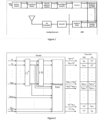
- Figure 1 illustrates an exemplary embodiment of the transmitter of the present invention that can be used in OFDM systems.
- the intended transmitted data bits
- bits are first mapped into complex symbols using a constellation mapper, e.g., by employing a quadrature amplitude modulation (QAM) scheme.
- QAM quadrature amplitude modulation
- the symbols are encoded and transformed to the time domain via the inverse fast Fourier transform (IFFT) unit.
- IFFT inverse fast Fourier transform
- Guard interval is inserted in order to enable the elimination of the inter-symbol interference at the receiver.
- the signal is converted from digital to analog, before being up-converted and transmitted. It is to be noted that the imperfections of the up-conversion unit cause image interference.
- the transmission is organized in two consecutive time slots.
- the encoder shown in Figure 2 takes as input the symbols that are intended to be uploaded over the N subcarriers in a particular time slot, and returns a rearranged transformation of those symbols.
- ( ⁇ ) ⁇ is the complex conjugate operator.
- the elements in the first and second column of the row n of the matric v represent the symbols that will be uploaded to the subcarrier n at the second and the first consecutive time slots, respectively.
- Figure 3 demonstrates an exemplary embodiment of the receiver of the present invention that can be used in OFDM systems.
- the received signal is first down-converted. Note that the down conversion unit causes image interference due to the hardware imperfections.
- the guard interval is removed and the signal is forwarded to the multi-carrier demodulator, which in the case of OFDM is a fast Fourier transform (FFT) unit, and the guard intervals are removed.
- FFT fast Fourier transform
- h(n) represent the baseband equivalent fading gain in subcarrier n
- AWGN circularly symmetric white Gaussian noise
- the parameters c 1,n , c 2,n , C 1,N+1-n , C 2,N+1-n are forwarded to the combiner. Note that a similar estimation method has been presented in " Y. Jin, J. Kwon, Y. Lee, J. Ahn, W. Choi, and D. Lee, "Additional diversity gain in OFDM receivers under the influence of IQ imbalances," in Proc. IEEE Int. Conf. Common. (ICC), Jun. 2007, pp. 5915-5920 .”
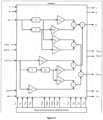
- the two consecutive received baseband signals are forwarded to the combiner, which uses and combines the received signals in the first and the second time slot on the subcarriers n and N+1-n, as illustrated in Figure 4 .
- T stands for the symbol duration.
- the combiner's output is forwarded to the constellation demapper, which estimates the transmitted symbols using a typical detector (e.g., maximum likelihood detector - MLD).
- the present invention results in minimizing the impact of image interference, which is the main disadvantage of the low-cost transceivers. Furthermore, it achieves diversity gain of second order, which improves the communication quality for a given transmit power.
- the gain achieved by the proposed method with QPSK is about 7 dB compared to the ideal RF front-end with BPSK, whereas in case of the "realistic RF front-end", an error floor is observed at a SER of 6 ⁇ 10 -3 .
Landscapes
- Engineering & Computer Science (AREA)
- Computer Networks & Wireless Communication (AREA)
- Signal Processing (AREA)
- Noise Elimination (AREA)
- Radio Transmission System (AREA)
- Near-Field Transmission Systems (AREA)
Description
- The present innovation is related to a method which exploits the inevitable image interference, i.e. a low complexity method for exploiting the image interference in multi-carrier wireless systems, due to the transmitter's and receiver's radio frequency (RF) front-end imperfections, in multi-carrier wireless systems, such as systems that use orthogonal frequency division modulation (OFDM) schemes.
- Multi-carrier techniques can significantly improve the spectrum efficiency of wireless communication systems. Therefore, they are included in several communication standards.
- The main advantage of multi-carrier over single-carrier systems are their ability to cope with severe channel conditions, such as narrowband interference and frequency-selective fading due to multipath, without using complex channel equalization filters. This is because multi-carrier signals may be viewed as the composition of several narrowband signals.
- Typically, multi-carrier wireless transceivers follow super-heterodyne architecture. This architecture requires several analog components in order to achieve the acceptable communication signal quality. However, super-heterodyne architecture considerably increases the overall power consumption and cost. As a result, zero intermediate frequency (IF) architecture, in which the bandpass signal is converted directly to baseband, has gained increased popularity. However, zero-IF transceivers suffer from radio frequency (RF) imperfections that cause image frequency band interference. Image interference can significantly degrade the multi-carrier system's performance.
- To overcome this drawback, various image interference compensation methods have been proposed. In particular,
US 7822399 B2 of Telefonaktiebolaget LM Ericsson discloses a method for the estimation of the signal received on the image subcarrier and the compensation of the impact of image interference, by subtracting the estimated image signal from the desired signal. -
WO 2014/050382 discloses a compensation process of removing an image component in a quadrature-demodulated signal. This method includes a quadrature demodulation compensation component that compensates for the quadrature-demodulated signal including an in-phase (I) signal and a quadrature (Q) signal. In other words, it is configured to compensate for a difference between frequency characteristic of a first filter that performs filtering of the I signal and frequency characteristic of a second filter that performs filtering of the Q signal. - Further relevant prior art is disclosed in non patent document XP031126613.
- The present invention aims to deal with the problem of performance degradation due to the RF front-end imperfection, as well as to provide diversity gain, which significantly improves the quality-of-service (QoS) for a fixed transmit power.
- The present invention proposes a low-complexity method for exploiting the image interference in single-antenna multi-carrier systems. The proposed method compensates the negative effect of image interference, while, at the same time, it achieves diversity order of two. It comprises the steps of encoding the modulated symbols at the transmitter, and combining the signals received at image subcarriers at the receiver.
- This method requires neither feedback from the receiver nor extra transmit power.
- Nevertheless, it allows low-cost transceivers, in which the effect of image interference is more severe, to use high-order constellations.
- According to the preferred embodiment of the invention, said steps are carried out in that order.
-
-
Figure 1 shows a schematical view of the transmitter according to the invention. -
Figure 2 shows a schematical view of the transmitter's encoder according to the invention. -
Figure 3 shows a schematical view of the receiver according to the invention. -
Figure 4 shows a schematical view of the receiver's combiner according to the invention. -
Figure 5 shows a graph showing the symbol error rate (SER) performance of the proposed method in comparison with the prior art and the ideal RF scenario. - The invention is defined in the appended claims. Exemplary embodiments which do not fall within the scope of the claims are not part of the invention but are described for illustrative purpose only, since they are useful for understanding the invention.
- The present invention provides a method for exploiting the image interference in single-antenna multi-carrier wireless systems. In the presence of image interference, there is an error floor, when the conventional receiver is used. The method of the present invention is capable of removing that floor and obtaining better performance even from the ideal case, in which the impact of image interference is not taken into consideration.
-
Figure 1 illustrates an exemplary embodiment of the transmitter of the present invention that can be used in OFDM systems. Specifically, the intended transmitted data (bits) are first mapped into complex symbols using a constellation mapper, e.g., by employing a quadrature amplitude modulation (QAM) scheme. Then, the symbols are encoded and transformed to the time domain via the inverse fast Fourier transform (IFFT) unit. Guard interval is inserted in order to enable the elimination of the inter-symbol interference at the receiver. Finally, the signal is converted from digital to analog, before being up-converted and transmitted. It is to be noted that the imperfections of the up-conversion unit cause image interference. - The transmission is organized in two consecutive time slots. The encoder shown in
Figure 2 takes as input the symbols that are intended to be uploaded over the N subcarriers in a particular time slot, and returns a rearranged transformation of those symbols. In particular, if the input of the encoder is the following:

-
Figure 3 demonstrates an exemplary embodiment of the receiver of the present invention that can be used in OFDM systems. The received signal is first down-converted. Note that the down conversion unit causes image interference due to the hardware imperfections. Next, the guard interval is removed and the signal is forwarded to the multi-carrier demodulator, which in the case of OFDM is a fast Fourier transform (FFT) unit, and the guard intervals are removed. The baseband equivalent received signals in the first and second time slot on subcarrier n, with n<N/2 +1, are as follows:


- If a pilot sequence has been transmitted, the received baseband signal is forwarded to the channel and image interference coefficients estimator, which estimates the distorted (due to image interference) channels' coefficients, c1,n, c2,n, c1,N+1-n, c2,N+1-n, as


- In the above expressions, the parameters εi (i=1,2,3,4) represent estimation errors, due to the additive noise. Next, the parameters c1,n, c2,n, C1,N+1-n, C2,N+1-n are forwarded to the combiner. Note that a similar estimation method has been presented in "Y. Jin, J. Kwon, Y. Lee, J. Ahn, W. Choi, and D. Lee, "Additional diversity gain in OFDM receivers under the influence of IQ imbalances," in Proc. IEEE Int. Conf. Common. (ICC), Jun. 2007, pp. 5915-5920."
- If an information message has been transmitted, the two consecutive received baseband signals are forwarded to the combiner, which uses and combines the received signals in the first and the second time slot on the subcarriers n and N+1-n, as illustrated in
Figure 4 . Note that inFigure 4 , T stands for the symbol duration. The combiner's output is forwarded to the constellation demapper, which estimates the transmitted symbols using a typical detector (e.g., maximum likelihood detector - MLD). - According to the method described, the present invention results in minimizing the impact of image interference, which is the main disadvantage of the low-cost transceivers. Furthermore, it achieves diversity gain of second order, which improves the communication quality for a given transmit power.
- The SER performance of the present invention for binary phase shift keying (BPSK), quadrature phase shift keying (QPSK) and 16-QAM constellations, in comparison with the case of realistic transceivers with uncompensated image interference, and the ideal RF front-end transceivers scenario, in which the image interference effect has been neglected, are presented in
Figure 5 . In the case of "realistic RF front-end", and "proposed method", the amount of attenuation of the image band for both the transmitter and receiver are set to 20dB. This is considered the worst case scenario. It can be observed that, for fixed constellation, the performance of the present invention is improved in comparison to both the "realistic RF front-end" scenario and the "ideal RF front-end". Moreover, at a SER of 10-3, which is a practical requirement in several wireless communication standards, the gain achieved by the proposed method with QPSK is about 7 dB compared to the ideal RF front-end with BPSK, whereas in case of the "realistic RF front-end", an error floor is observed at a SER of 6 × 10⁻³.
Claims (10)
- A low complexity method for converting image interference caused in multi-carrier wireless systems into diversity gain, said multi-carrier wireless system comprising :- a multi-carrier single-antenna transmitter;- a multi-carrier single-antenna receiver;- wherein the transmitter comprises an encoder; and- wherein the receiver comprises a combiner configured to process the symbols received in image subcarriers in two consecutive time slots wherein said transmitter and receiver cause said image interference,the method being characterized in that it comprises the steps of- encoding the modulated symbols at the transmitter, and- combining signals received at image subcarriers at the receiver, wherein said steps are carried out in that order,further whereini) transmission information encoding is performed during both channel estimation and data transmission phases;ii) the combiner which is incorporated at the receiver is used during the data transmission phase;iii) a conventional maximum likelihood detector MLD is used for symbol estimation, whereas the combiners output is an in-phase and quadrature imbalance IQI-free signal, thereby providing gain diversity order of 2.
- Method according to the preceding claim 1, wherein an error floor which is generated in the presence of said image interference occurring when the conventional receiver is used, is removed.
- Method according to one of the preceding claims 1 or 2, wherein with said transmitter that can be used in OFDM systems, intended transmitted data bits are first mapped into complex symbols using a constellation mapper, wherein the symbols are then encoded and transformed to the time domain via an inverse fast Fourier transform IFFT unit, further wherein a guard interval is inserted in order to enable the elimination of the intersymbol interference at the receiver, finally wherein the signal is converted from digital to analog, before being up-converted and transmitted, whereas the imperfections of the up-conversion unit cause image interference.
- Method according to claim 3, wherein with said transmitter that is used in OFDM systems, the intended transmitted data bits are first mapped into complex symbols using a constellation mapper by employing a quadrature amplitude modulation QAM scheme, wherein the symbols are then encoded and transformed to the time domain via an inverse fast Fourier transform IFFT unit.
- Method according to one of the preceding claims, wherein the transmission is organized in two consecutive time slots, wherein the encoder is configured to take as input the symbols that are intended to be uploaded over the N subcarriers in a particular time slot, and returns a rearranged transformation of those symbols.
- Method according to claim 5, wherein the input of the encoder is the following:


- Method according to one of the preceding claims, wherein the receiver is used in OFDM systems, wherein the received signal is first down-converted, whereas the down conversion unit causes image interference due to hardware imperfections wherein next, the guard interval is removed, and the signal is forwarded to the multi-carrier demodulator, which in the case of OFDM is a fast Fourier transform FFT unit, and the guard intervals are removed,wherein the baseband equivalent received signals in the first and second time slot on subcarrier n, with n<N/2 +1, are as follows:

 respectively, while the baseband equivalent received signals in the first and second time slot on the (N+1-n) image subcarrier are as follows:
 where κt(n), λt(n) and κr(n), λr(n) are complex coefficients that model the impact of image interference at the transmitter and receiver, respectively, on subcarrier n,wherein h(n) represent the baseband equivalent fading gain in subcarrier n, whereas zi(n) (i=1,2) stands for the circularly symmetric white Gaussian noise AWGN that is added to the received signal on subcarrier n in the ith time slot.
 - Method according to claim 7, wherein the channels for the image subcarriers are configured to remain constant over the two consecutive time slots.
- Method according to one of both claims 7 or 8, wherein if a pilot sequence has been transmitted, the received baseband signal is forwarded to the channel and image interference coefficients estimator, which is configured to estimate the distorted due to image interference channels' coefficients c1,n, c2,n, c1,N+1-n, c2,N+1-n, as

 wherein, the parameters εi (i = 1,2,3,4) represent estimation errors, due to the additive noise;wherein next, the parameters c1,n, c2,n, c1,N+1-n, c2,N+1-n are forwarded to the combiner.
 - Method according to one of the preceding claims, wherein if an information message has been transmitted, the two consecutive received baseband signals are forwarded to the combiner, which is configured to use and combine the received signals in the first and the second time slot on the subcarriers n and N+1-n, wherein T stands for the symbol duration;
wherein the combiner's output is forwarded to the constellation demapper, which is configured to estimate the transmitted symbols using a typical detector, such as a maximum likelihood detector MLD.
Applications Claiming Priority (1)
| Application Number | Priority Date | Filing Date | Title |
|---|---|---|---|
| GR20170100026A GR1009247B (en) | 2017-01-12 | 2017-01-12 | A method for the exploitation of image interference in multi-carrier wireless systems |
Publications (3)
| Publication Number | Publication Date |
|---|---|
| EP3349361A1 EP3349361A1 (en) | 2018-07-18 |
| EP3349361C0 EP3349361C0 (en) | 2023-06-07 |
| EP3349361B1 true EP3349361B1 (en) | 2023-06-07 |
Family
ID=59062048
Family Applications (1)
| Application Number | Title | Priority Date | Filing Date |
|---|---|---|---|
| EP18151433.2A Active EP3349361B1 (en) | 2017-01-12 | 2018-01-12 | A method for the exploitation of image interference in multi-carrier wireless systems |
Country Status (2)
| Country | Link |
|---|---|
| EP (1) | EP3349361B1 (en) |
| GR (1) | GR1009247B (en) |
Family Cites Families (4)
| Publication number | Priority date | Publication date | Assignee | Title |
|---|---|---|---|---|
| US8169889B2 (en) * | 2004-02-18 | 2012-05-01 | Qualcomm Incorporated | Transmit diversity and spatial spreading for an OFDM-based multi-antenna communication system |
| US7668224B2 (en) * | 2005-08-16 | 2010-02-23 | Texas Instruments Incorporated | Encoding for digital communications in a multiple-input, multiple-output environment |
| US20070076804A1 (en) * | 2005-09-30 | 2007-04-05 | Texas Instruments Inc. | Image-rejecting channel estimator, method of image-rejection channel estimating and an OFDM receiver employing the same |
| JP2007258904A (en) * | 2006-03-22 | 2007-10-04 | Sony Corp | Wireless communication device |
-
2017
- 2017-01-12 GR GR20170100026A patent/GR1009247B/en active IP Right Grant
-
2018
- 2018-01-12 EP EP18151433.2A patent/EP3349361B1/en active Active
Also Published As
| Publication number | Publication date |
|---|---|
| EP3349361C0 (en) | 2023-06-07 |
| GR1009247B (en) | 2018-03-15 |
| EP3349361A1 (en) | 2018-07-18 |
Similar Documents
| Publication | Publication Date | Title |
|---|---|---|
| US8400994B2 (en) | Method for transmitting downlink reference signals in a multi-antenna wireless communication system | |
| US7869538B2 (en) | System and method for I/Q imbalance compensation | |
| KR101564479B1 (en) | Method and system for reduced complexity channel estimation and interference cancellation for v-mimo demodulation | |
| US8081695B2 (en) | Channel estimation using frequency smoothing | |
| US9300407B2 (en) | Channel estimation for optical orthogonal frequency division multiplexing systems | |
| US7577206B2 (en) | OFDM signal receiving apparatus and method for estimating common phase error of OFDM signals using data subcarriers | |
| US7961800B2 (en) | Adaptive radio/modulation apparatus, receiver apparatus, wireless communication system, and wireless communication method | |
| US7184714B1 (en) | Frequency domain estimation of IQ imbalance in a wireless OFDM direct conversion receiver using loopback connection | |
| Schenk et al. | Estimation and compensation of frequency selective TX/RX IQ imbalance in MIMO OFDM systems | |
| US8064532B2 (en) | Method and scheme for space-time coded cochannel interference cancellation | |
| US7675999B2 (en) | Multicarrier receiver and method with phase noise reduced signal | |
| US8848777B2 (en) | Receiving apparatus and method for receiving signals in a wireless communication system with improved equalization performance | |
| US20100061474A1 (en) | Fft spreading among selected ofdm sub-carriers | |
| EP3427420B1 (en) | Method and apparatus for i-q decoupled ofdm modulation and demodulation | |
| Kadel | Diversity and equalization in frequency domain a robust and flexible receiver technology for broadband mobile communication systems | |
| US7609772B2 (en) | Apparatus and method for optimally compensating for imbalance between in-phase and quadrature-phase in a zero-IF OFDM receiver | |
| JP2006287931A (en) | Efficient channel tracking for packet-based OFDM systems | |
| US20090034503A1 (en) | Receiver and reception method for estimating channel in an orthogonal frequency division multiple access system | |
| US8139544B1 (en) | Pilot tone processing systems and methods | |
| Dinis et al. | Iterative block-DFE techniques for single-carrier-based broadband communications with transmit/receive space diversity | |
| EP3349361A1 (en) | A method for the exploitation of image interference in multi-carrier wireless systems | |
| Dimitrov | Non-linear distortion noise cancellation for satellite return links | |
| CN103259549B (en) | Receiver circuit and the method for detecting data | |
| Sand et al. | Iterative channel estimation for high mobility broadband MC-CDMA systems | |
| KR100608916B1 (en) | Wireless Channel Compensation Method and Device in Orthogonal Frequency Division Multiplexing WLAN |
Legal Events
| Date | Code | Title | Description |
|---|---|---|---|
| PUAI | Public reference made under article 153(3) epc to a published international application that has entered the european phase |
Free format text: ORIGINAL CODE: 0009012 |
|
| STAA | Information on the status of an ep patent application or granted ep patent |
Free format text: STATUS: THE APPLICATION HAS BEEN PUBLISHED |
|
| AK | Designated contracting states |
Kind code of ref document: A1 Designated state(s): AL AT BE BG CH CY CZ DE DK EE ES FI FR GB GR HR HU IE IS IT LI LT LU LV MC MK MT NL NO PL PT RO RS SE SI SK SM TR |
|
| AX | Request for extension of the european patent |
Extension state: BA ME |
|
| STAA | Information on the status of an ep patent application or granted ep patent |
Free format text: STATUS: REQUEST FOR EXAMINATION WAS MADE |
|
| 17P | Request for examination filed |
Effective date: 20181224 |
|
| RBV | Designated contracting states (corrected) |
Designated state(s): AL AT BE BG CH CY CZ DE DK EE ES FI FR GB GR HR HU IE IS IT LI LT LU LV MC MK MT NL NO PL PT RO RS SE SI SK SM TR |
|
| STAA | Information on the status of an ep patent application or granted ep patent |
Free format text: STATUS: EXAMINATION IS IN PROGRESS |
|
| 17Q | First examination report despatched |
Effective date: 20190517 |
|
| GRAP | Despatch of communication of intention to grant a patent |
Free format text: ORIGINAL CODE: EPIDOSNIGR1 |
|
| STAA | Information on the status of an ep patent application or granted ep patent |
Free format text: STATUS: GRANT OF PATENT IS INTENDED |
|
| INTG | Intention to grant announced |
Effective date: 20220901 |
|
| GRAS | Grant fee paid |
Free format text: ORIGINAL CODE: EPIDOSNIGR3 |
|
| RIN1 | Information on inventor provided before grant (corrected) |
Inventor name: KAPINAS, VASILEIOS Inventor name: BOULOGEORGOS, ALEXANDROS APOSTOLOS Inventor name: SCHOBER, ROBERT Inventor name: KARAGIANNIDIS, GEORGIOS |
|
| GRAA | (expected) grant |
Free format text: ORIGINAL CODE: 0009210 |
|
| STAA | Information on the status of an ep patent application or granted ep patent |
Free format text: STATUS: THE PATENT HAS BEEN GRANTED |
|
| AK | Designated contracting states |
Kind code of ref document: B1 Designated state(s): AL AT BE BG CH CY CZ DE DK EE ES FI FR GB GR HR HU IE IS IT LI LT LU LV MC MK MT NL NO PL PT RO RS SE SI SK SM TR |
|
| REG | Reference to a national code |
Ref country code: GB Ref legal event code: FG4D |
|
| REG | Reference to a national code |
Ref country code: CH Ref legal event code: EP Ref country code: AT Ref legal event code: REF Ref document number: 1577905 Country of ref document: AT Kind code of ref document: T Effective date: 20230615 |
|
| REG | Reference to a national code |
Ref country code: DE Ref legal event code: R096 Ref document number: 602018050649 Country of ref document: DE |
|
| U01 | Request for unitary effect filed |
Effective date: 20230616 |
|
| U07 | Unitary effect registered |
Designated state(s): AT BE BG DE DK EE FI FR IT LT LU LV MT NL PT SE SI Effective date: 20230724 |
|
| REG | Reference to a national code |
Ref country code: LT Ref legal event code: MG9D |
|
| PG25 | Lapsed in a contracting state [announced via postgrant information from national office to epo] |
Ref country code: NO Free format text: LAPSE BECAUSE OF FAILURE TO SUBMIT A TRANSLATION OF THE DESCRIPTION OR TO PAY THE FEE WITHIN THE PRESCRIBED TIME-LIMIT Effective date: 20230907 Ref country code: ES Free format text: LAPSE BECAUSE OF FAILURE TO SUBMIT A TRANSLATION OF THE DESCRIPTION OR TO PAY THE FEE WITHIN THE PRESCRIBED TIME-LIMIT Effective date: 20230607 |
|
| REG | Reference to a national code |
Ref country code: GR Ref legal event code: EP Ref document number: 20230401540 Country of ref document: GR Effective date: 20231010 |
|
| PG25 | Lapsed in a contracting state [announced via postgrant information from national office to epo] |
Ref country code: RS Free format text: LAPSE BECAUSE OF FAILURE TO SUBMIT A TRANSLATION OF THE DESCRIPTION OR TO PAY THE FEE WITHIN THE PRESCRIBED TIME-LIMIT Effective date: 20230607 Ref country code: HR Free format text: LAPSE BECAUSE OF FAILURE TO SUBMIT A TRANSLATION OF THE DESCRIPTION OR TO PAY THE FEE WITHIN THE PRESCRIBED TIME-LIMIT Effective date: 20230607 |
|
| PG25 | Lapsed in a contracting state [announced via postgrant information from national office to epo] |
Ref country code: SK Free format text: LAPSE BECAUSE OF FAILURE TO SUBMIT A TRANSLATION OF THE DESCRIPTION OR TO PAY THE FEE WITHIN THE PRESCRIBED TIME-LIMIT Effective date: 20230607 |
|
| PG25 | Lapsed in a contracting state [announced via postgrant information from national office to epo] |
Ref country code: IS Free format text: LAPSE BECAUSE OF FAILURE TO SUBMIT A TRANSLATION OF THE DESCRIPTION OR TO PAY THE FEE WITHIN THE PRESCRIBED TIME-LIMIT Effective date: 20231007 |
|
| PG25 | Lapsed in a contracting state [announced via postgrant information from national office to epo] |
Ref country code: SM Free format text: LAPSE BECAUSE OF FAILURE TO SUBMIT A TRANSLATION OF THE DESCRIPTION OR TO PAY THE FEE WITHIN THE PRESCRIBED TIME-LIMIT Effective date: 20230607 Ref country code: SK Free format text: LAPSE BECAUSE OF FAILURE TO SUBMIT A TRANSLATION OF THE DESCRIPTION OR TO PAY THE FEE WITHIN THE PRESCRIBED TIME-LIMIT Effective date: 20230607 Ref country code: RO Free format text: LAPSE BECAUSE OF FAILURE TO SUBMIT A TRANSLATION OF THE DESCRIPTION OR TO PAY THE FEE WITHIN THE PRESCRIBED TIME-LIMIT Effective date: 20230607 Ref country code: IS Free format text: LAPSE BECAUSE OF FAILURE TO SUBMIT A TRANSLATION OF THE DESCRIPTION OR TO PAY THE FEE WITHIN THE PRESCRIBED TIME-LIMIT Effective date: 20231007 Ref country code: CZ Free format text: LAPSE BECAUSE OF FAILURE TO SUBMIT A TRANSLATION OF THE DESCRIPTION OR TO PAY THE FEE WITHIN THE PRESCRIBED TIME-LIMIT Effective date: 20230607 |
|
| PG25 | Lapsed in a contracting state [announced via postgrant information from national office to epo] |
Ref country code: PL Free format text: LAPSE BECAUSE OF FAILURE TO SUBMIT A TRANSLATION OF THE DESCRIPTION OR TO PAY THE FEE WITHIN THE PRESCRIBED TIME-LIMIT Effective date: 20230607 |
|
| U20 | Renewal fee for the european patent with unitary effect paid |
Year of fee payment: 7 Effective date: 20240129 |
|
| REG | Reference to a national code |
Ref country code: DE Ref legal event code: R097 Ref document number: 602018050649 Country of ref document: DE |
|
| PGFP | Annual fee paid to national office [announced via postgrant information from national office to epo] |
Ref country code: GR Payment date: 20240124 Year of fee payment: 7 |
|
| PLBE | No opposition filed within time limit |
Free format text: ORIGINAL CODE: 0009261 |
|
| STAA | Information on the status of an ep patent application or granted ep patent |
Free format text: STATUS: NO OPPOSITION FILED WITHIN TIME LIMIT |
|
| PGFP | Annual fee paid to national office [announced via postgrant information from national office to epo] |
Ref country code: GB Payment date: 20240330 Year of fee payment: 7 |
|
| 26N | No opposition filed |
Effective date: 20240308 |
|
| PG25 | Lapsed in a contracting state [announced via postgrant information from national office to epo] |
Ref country code: MC Free format text: LAPSE BECAUSE OF FAILURE TO SUBMIT A TRANSLATION OF THE DESCRIPTION OR TO PAY THE FEE WITHIN THE PRESCRIBED TIME-LIMIT Effective date: 20230607 |
|
| PG25 | Lapsed in a contracting state [announced via postgrant information from national office to epo] |
Ref country code: MC Free format text: LAPSE BECAUSE OF FAILURE TO SUBMIT A TRANSLATION OF THE DESCRIPTION OR TO PAY THE FEE WITHIN THE PRESCRIBED TIME-LIMIT Effective date: 20230607 |
|
| PGFP | Annual fee paid to national office [announced via postgrant information from national office to epo] |
Ref country code: CH Payment date: 20240729 Year of fee payment: 7 |
|
| PG25 | Lapsed in a contracting state [announced via postgrant information from national office to epo] |
Ref country code: IE Free format text: LAPSE BECAUSE OF NON-PAYMENT OF DUE FEES Effective date: 20240112 |
|
| PG25 | Lapsed in a contracting state [announced via postgrant information from national office to epo] |
Ref country code: IE Free format text: LAPSE BECAUSE OF NON-PAYMENT OF DUE FEES Effective date: 20240112 |
|
| PG25 | Lapsed in a contracting state [announced via postgrant information from national office to epo] |
Ref country code: CY Free format text: LAPSE BECAUSE OF FAILURE TO SUBMIT A TRANSLATION OF THE DESCRIPTION OR TO PAY THE FEE WITHIN THE PRESCRIBED TIME-LIMIT; INVALID AB INITIO Effective date: 20180112 |
|
| REG | Reference to a national code |
Ref country code: CH Ref legal event code: PL |
|
| PG25 | Lapsed in a contracting state [announced via postgrant information from national office to epo] |
Ref country code: HU Free format text: LAPSE BECAUSE OF FAILURE TO SUBMIT A TRANSLATION OF THE DESCRIPTION OR TO PAY THE FEE WITHIN THE PRESCRIBED TIME-LIMIT; INVALID AB INITIO Effective date: 20180112 |
|
| U90 | Renewal fees not paid: noting of loss of rights |
Free format text: RENEWAL FEE NOT PAID FOR YEAR 08 Effective date: 20250819 |
|
| GBPC | Gb: european patent ceased through non-payment of renewal fee |
Effective date: 20250112 |
|
| PG25 | Lapsed in a contracting state [announced via postgrant information from national office to epo] |
Ref country code: GR Free format text: LAPSE BECAUSE OF NON-PAYMENT OF DUE FEES Effective date: 20250805 |
|
| PG25 | Lapsed in a contracting state [announced via postgrant information from national office to epo] |
Ref country code: GB Free format text: LAPSE BECAUSE OF NON-PAYMENT OF DUE FEES Effective date: 20250112 |
|
| PG25 | Lapsed in a contracting state [announced via postgrant information from national office to epo] |
Ref country code: CH Free format text: LAPSE BECAUSE OF NON-PAYMENT OF DUE FEES Effective date: 20250131 |
|
| U93 | Unitary patent lapsed |
Free format text: RENEWAL FEE NOT PAID Effective date: 20250131 |
|
| PG25 | Lapsed in a contracting state [announced via postgrant information from national office to epo] |
Ref country code: TR Free format text: LAPSE BECAUSE OF FAILURE TO SUBMIT A TRANSLATION OF THE DESCRIPTION OR TO PAY THE FEE WITHIN THE PRESCRIBED TIME-LIMIT Effective date: 20230607 |