EP3349221A1 - Filler and multicore cable having same - Google Patents
Filler and multicore cable having same Download PDFInfo
- Publication number
- EP3349221A1 EP3349221A1 EP16844600.3A EP16844600A EP3349221A1 EP 3349221 A1 EP3349221 A1 EP 3349221A1 EP 16844600 A EP16844600 A EP 16844600A EP 3349221 A1 EP3349221 A1 EP 3349221A1
- Authority
- EP
- European Patent Office
- Prior art keywords
- frame
- optical unit
- frame part
- support
- filler
- Prior art date
- Legal status (The legal status is an assumption and is not a legal conclusion. Google has not performed a legal analysis and makes no representation as to the accuracy of the status listed.)
- Granted
Links
Images

Classifications
-
- G—PHYSICS
- G02—OPTICS
- G02B—OPTICAL ELEMENTS, SYSTEMS OR APPARATUS
- G02B6/00—Light guides; Structural details of arrangements comprising light guides and other optical elements, e.g. couplings
- G02B6/44—Mechanical structures for providing tensile strength and external protection for fibres, e.g. optical transmission cables
- G02B6/4401—Optical cables
- G02B6/441—Optical cables built up from sub-bundles
-
- G—PHYSICS
- G02—OPTICS
- G02B—OPTICAL ELEMENTS, SYSTEMS OR APPARATUS
- G02B6/00—Light guides; Structural details of arrangements comprising light guides and other optical elements, e.g. couplings
- G02B6/44—Mechanical structures for providing tensile strength and external protection for fibres, e.g. optical transmission cables
- G02B6/4401—Optical cables
- G02B6/4415—Cables for special applications
- G02B6/4427—Pressure resistant cables, e.g. undersea cables
-
- G—PHYSICS
- G02—OPTICS
- G02B—OPTICAL ELEMENTS, SYSTEMS OR APPARATUS
- G02B6/00—Light guides; Structural details of arrangements comprising light guides and other optical elements, e.g. couplings
- G02B6/44—Mechanical structures for providing tensile strength and external protection for fibres, e.g. optical transmission cables
- G02B6/4401—Optical cables
- G02B6/4429—Means specially adapted for strengthening or protecting the cables
- G02B6/44384—Means specially adapted for strengthening or protecting the cables the means comprising water blocking or hydrophobic materials
-
- G—PHYSICS
- G02—OPTICS
- G02B—OPTICAL ELEMENTS, SYSTEMS OR APPARATUS
- G02B6/00—Light guides; Structural details of arrangements comprising light guides and other optical elements, e.g. couplings
- G02B6/44—Mechanical structures for providing tensile strength and external protection for fibres, e.g. optical transmission cables
- G02B6/4439—Auxiliary devices
- G02B6/4459—Ducts; Conduits; Hollow tubes for air blown fibres
-
- H—ELECTRICITY
- H01—ELECTRIC ELEMENTS
- H01B—CABLES; CONDUCTORS; INSULATORS; SELECTION OF MATERIALS FOR THEIR CONDUCTIVE, INSULATING OR DIELECTRIC PROPERTIES
- H01B13/00—Apparatus or processes specially adapted for manufacturing conductors or cables
- H01B13/22—Sheathing; Armouring; Screening; Applying other protective layers
-
- H—ELECTRICITY
- H01—ELECTRIC ELEMENTS
- H01B—CABLES; CONDUCTORS; INSULATORS; SELECTION OF MATERIALS FOR THEIR CONDUCTIVE, INSULATING OR DIELECTRIC PROPERTIES
- H01B13/00—Apparatus or processes specially adapted for manufacturing conductors or cables
- H01B13/22—Sheathing; Armouring; Screening; Applying other protective layers
- H01B13/221—Sheathing; Armouring; Screening; Applying other protective layers filling-up interstices
-
- H—ELECTRICITY
- H01—ELECTRIC ELEMENTS
- H01B—CABLES; CONDUCTORS; INSULATORS; SELECTION OF MATERIALS FOR THEIR CONDUCTIVE, INSULATING OR DIELECTRIC PROPERTIES
- H01B13/00—Apparatus or processes specially adapted for manufacturing conductors or cables
- H01B13/22—Sheathing; Armouring; Screening; Applying other protective layers
- H01B13/24—Sheathing; Armouring; Screening; Applying other protective layers by extrusion
- H01B13/245—Sheathing; Armouring; Screening; Applying other protective layers by extrusion of metal layers
-
- H—ELECTRICITY
- H01—ELECTRIC ELEMENTS
- H01B—CABLES; CONDUCTORS; INSULATORS; SELECTION OF MATERIALS FOR THEIR CONDUCTIVE, INSULATING OR DIELECTRIC PROPERTIES
- H01B13/00—Apparatus or processes specially adapted for manufacturing conductors or cables
- H01B13/32—Filling or coating with impervious material
-
- H—ELECTRICITY
- H01—ELECTRIC ELEMENTS
- H01B—CABLES; CONDUCTORS; INSULATORS; SELECTION OF MATERIALS FOR THEIR CONDUCTIVE, INSULATING OR DIELECTRIC PROPERTIES
- H01B7/00—Insulated conductors or cables characterised by their form
- H01B7/14—Submarine cables
-
- H—ELECTRICITY
- H01—ELECTRIC ELEMENTS
- H01B—CABLES; CONDUCTORS; INSULATORS; SELECTION OF MATERIALS FOR THEIR CONDUCTIVE, INSULATING OR DIELECTRIC PROPERTIES
- H01B7/00—Insulated conductors or cables characterised by their form
- H01B7/17—Protection against damage caused by external factors, e.g. sheaths or armouring
- H01B7/18—Protection against damage caused by wear, mechanical force or pressure; Sheaths; Armouring
-
- H—ELECTRICITY
- H01—ELECTRIC ELEMENTS
- H01B—CABLES; CONDUCTORS; INSULATORS; SELECTION OF MATERIALS FOR THEIR CONDUCTIVE, INSULATING OR DIELECTRIC PROPERTIES
- H01B7/00—Insulated conductors or cables characterised by their form
- H01B7/17—Protection against damage caused by external factors, e.g. sheaths or armouring
- H01B7/18—Protection against damage caused by wear, mechanical force or pressure; Sheaths; Armouring
- H01B7/1875—Multi-layer sheaths
-
- H—ELECTRICITY
- H01—ELECTRIC ELEMENTS
- H01B—CABLES; CONDUCTORS; INSULATORS; SELECTION OF MATERIALS FOR THEIR CONDUCTIVE, INSULATING OR DIELECTRIC PROPERTIES
- H01B7/00—Insulated conductors or cables characterised by their form
- H01B7/17—Protection against damage caused by external factors, e.g. sheaths or armouring
- H01B7/18—Protection against damage caused by wear, mechanical force or pressure; Sheaths; Armouring
- H01B7/1895—Internal space filling-up means
-
- H—ELECTRICITY
- H01—ELECTRIC ELEMENTS
- H01B—CABLES; CONDUCTORS; INSULATORS; SELECTION OF MATERIALS FOR THEIR CONDUCTIVE, INSULATING OR DIELECTRIC PROPERTIES
- H01B7/00—Insulated conductors or cables characterised by their form
- H01B7/17—Protection against damage caused by external factors, e.g. sheaths or armouring
- H01B7/18—Protection against damage caused by wear, mechanical force or pressure; Sheaths; Armouring
- H01B7/24—Devices affording localised protection against mechanical force or pressure
-
- H—ELECTRICITY
- H01—ELECTRIC ELEMENTS
- H01B—CABLES; CONDUCTORS; INSULATORS; SELECTION OF MATERIALS FOR THEIR CONDUCTIVE, INSULATING OR DIELECTRIC PROPERTIES
- H01B9/00—Power cables
- H01B9/005—Power cables including optical transmission elements
-
- H—ELECTRICITY
- H01—ELECTRIC ELEMENTS
- H01B—CABLES; CONDUCTORS; INSULATORS; SELECTION OF MATERIALS FOR THEIR CONDUCTIVE, INSULATING OR DIELECTRIC PROPERTIES
- H01B9/00—Power cables
- H01B9/02—Power cables with screens or conductive layers, e.g. for avoiding large potential gradients
- H01B9/027—Power cables with screens or conductive layers, e.g. for avoiding large potential gradients composed of semi-conducting layers
-
- H—ELECTRICITY
- H01—ELECTRIC ELEMENTS
- H01B—CABLES; CONDUCTORS; INSULATORS; SELECTION OF MATERIALS FOR THEIR CONDUCTIVE, INSULATING OR DIELECTRIC PROPERTIES
- H01B9/00—Power cables
- H01B9/04—Concentric cables
-
- H—ELECTRICITY
- H01—ELECTRIC ELEMENTS
- H01B—CABLES; CONDUCTORS; INSULATORS; SELECTION OF MATERIALS FOR THEIR CONDUCTIVE, INSULATING OR DIELECTRIC PROPERTIES
- H01B7/00—Insulated conductors or cables characterised by their form
- H01B7/17—Protection against damage caused by external factors, e.g. sheaths or armouring
- H01B7/28—Protection against damage caused by moisture, corrosion, chemical attack or weather
- H01B7/2806—Protection against damage caused by corrosion
-
- H—ELECTRICITY
- H01—ELECTRIC ELEMENTS
- H01B—CABLES; CONDUCTORS; INSULATORS; SELECTION OF MATERIALS FOR THEIR CONDUCTIVE, INSULATING OR DIELECTRIC PROPERTIES
- H01B7/00—Insulated conductors or cables characterised by their form
- H01B7/17—Protection against damage caused by external factors, e.g. sheaths or armouring
- H01B7/28—Protection against damage caused by moisture, corrosion, chemical attack or weather
- H01B7/2813—Protection against damage caused by electrical, chemical or water tree deterioration
Definitions
- the present invention relates to a filler and a multicore cable having the same.
- the core parts are arranged to be almost symmetric with respect to a center portion of the multicore cable and a protective layer is provided along outer surfaces of the core parts.
- the multicore cable since the multicore cable includes the core parts, the roundness of the multicore cable may be difficult to maintain.
- an external force such as lateral pressure may be applied thereto and thus the core parts included in the multicore part may be damaged.
- a filler is necessary to maintain the roundness of the multicore cable and protect the core parts included in the multicore part when the multicore cable is installed or when an external force such as lateral pressure is applied to the multicore part.
- power cables for power transmission are manufactured in the form of a composite cable with optical units having optical fibers to simultaneously transmit power and information.
- An optical cable with optical fibers is more advantageous than an existing copper line in terms of low loss characteristics, transmission characteristics such as a high bandwidth, etc., but has lower mechanical strength than a copper line and is thus a transmission medium having low mechanical reliability. Actually, a failure (disconnection, bending, or the like) may occur due to mechanical vulnerability of the optical fiber and various internal/external causes.
- the present invention is directed to a filler for maintaining the roundness of a multicore cable having a plurality of core parts.
- the present invention is also directed to a filler for accommodating and protecting an optical unit when a multicore cable is manufactured in the form of a composite cable having the optical unit.
- the present invention is also directed to a filler for preventing damage to core parts and an optical unit included in a multicore cable when the multicore cable is installed or when an external force such as lateral pressure is applied to the multicore cable.
- a filler which is disposed between a core part and a protective layer of a multicore cable having a plurality of the core parts and the protective layer surrounding the plurality of core parts, wherein each the core part comprises a conductor, an inner semiconducting layer, an insulating layer, an outer semiconducting layer, a metal sheath and a polymeric sheath, the filler comprising: a frame part including a first frame part and a second frame part which are symmetric to each other; a rotating part configured to connect the first frame part and the second frame part; and a cut part dividing the frame part into the first frame part and the second frame part, wherein the filler is opened or closed by being rotated by a certain angle about the rotating part, and each of the first frame part and the second frame part comprises: an outer frame part formed in a circular arc shape; an inner frame part; and a support part configured to connect the outer frame part and the inner frame part.
- the filler further comprising: optical unit accommodating part frames respectively formed at the first frame part and the second frame part; and an optical unit accommodating part configured to be opened or closed as the filler is rotated about the rotating part.
- the filler wherein the cut part comprises: an upper cut part formed at the outer frame part; and a lower cut part formed at the inner frame part, wherein a length of the lower cut part is equal to or less than half an internal diameter of the optical unit accommodating part.
- a length of the upper cut part is equal to or less than half the internal diameter of the optical unit accommodating part.
- the filler wherein at least a portion of the support part connects the frame part and the optical unit accommodating part.
- the filler wherein the support part comprises: a frame support part configured to connect the outer frame part and the inner frame part; and an accommodating part support part configured to connect and support the optical unit accommodating part frames and the frame support part.
- the filler wherein the accommodating part support part tapers from the frame support part toward the optical unit accommodating part frames.
- the filler wherein one end of the outer frame part is connected to the optical unit accommodating part and another end thereof is connected to the inner frame part, the frame support part is formed between the one end and the other end of the outer frame part, and a length from a location of the frame support part to the one end is shorter than a length from the location of the frame support part to the other end.
- the filler wherein one end of the optical unit accommodating part frame is connected to the outer frame part and another end thereof is connected to the inner frame part, the accommodating part support part is formed between the one end and the other end of the optical unit accommodating part frame, and a length from a location of the accommodating part support part to the one end is shorter than a length from the location of the accommodating part support part to the other end.
- a multicore cable which includes a plurality of core parts, a protective layer surrounding the plurality of core parts and a filler disposed between the core part and the protective layer, wherein each the core part comprises a conductor, an inner semiconducting layer, an insulating layer, an outer semiconducting layer, a metal sheath and a polymeric sheath, the filler comprising: a frame part including a first frame part and a second frame part which are symmetric to each other; a rotating part configured to connect the first frame part and the second frame part; and a cut part dividing the frame part into the first frame part and the second frame part, wherein the filler is opened or closed by being rotated by a certain angle about the rotating part, and each of the first frame part and the second frame part comprises: an outer frame part formed in a circular arc shape, and facing the protective layer; an inner frame part facing the core part; and a support part configured to connect the outer frame part and the inner frame part.
- each of the fillers further comprises: optical unit accommodating part frames respectively formed at the first frame part and the second frame part; and an optical unit accommodating part configured to be opened or closed as the filler is rotated about the rotating part.
- the multicore cable wherein an optical unit is accommodated in the optical unit accommodating part, and an internal diameter of the optical unit accommodating part is greater than or equal to an external diameter of the optical unit.
- the multicore cable wherein the cut part comprises: an upper cut part formed at an outer side of the optical unit accommodating part in a radial direction of the multicore cable; and a lower cut part formed at an inner side of the optical unit accommodating part in the radial direction of the multicore cable, wherein a length of the lower cut part is equal to or less than half an external diameter of the optical unit.
- the multicore cable wherein a length of the upper cut part is equal to or less than half the external diameter of the optical unit.
- the multicore cable wherein at least a portion of the support part connects the frame part and the optical unit accommodating part.
- the support part comprises: a frame support part configured to connect and support the outer frame part and the inner frame part; and an accommodating part support part configured to connect and support the optical unit accommodating part frames and the frame support part.
- the multicore cable wherein the accommodating part support part tapers from the frame support part toward the optical unit accommodating part frames.
- the multicore cable wherein one end of the outer frame part is connected to the optical unit accommodating part and another end thereof is connected to the inner frame part, the frame support part is formed between the one end and the other end of the outer frame part, and a length from a location of the frame support part to the one end is shorter than a length from the location of the frame support part to the other end.
- the multicore cable wherein one end of the optical unit accommodating part frame is connected to the outer frame part and another end thereof is connected to the inner frame part, the accommodating part support part is formed between the one end and the other end of the optical unit accommodating part frame, and a length from a location of the accommodating part support part to the one end is shorter than a length from the location of the accommodating part support part to the other end.
- the roundness of a multicore cable with a plurality of core parts can be maintained using a filler provided between the core parts and an external protective layer.
- the filler can accommodate and protect the optical unit.
- the core parts and the optical unit included in multicore cable can be prevented from being damaged due to the filler when the multicore cable is installed or when an external force such as lateral pressure is applied to the multicore cable.
- 'multicore cable' is defined as a cable with a plurality of power line units (hereinafter referred to as 'core parts') each having a conductor, an inner semiconducting layer, an insulating layer, and an outer semiconducting layer and configured to transmit power.
- 'core parts' power line units
- a structure of a multicore cable which is in the form of an optical fiber and power line composite cable having an optical unit will be described.
- a filler according to the present invention will be described.
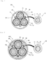
- FIG. 1 is a cross-sectional view of a multicore cable 1000 in the form of an optical fiber and power line composite cable with optical units 100, according to the related art.
- FIG. 1 illustrates the multicore cable 1000 which is a three-phase cable having three core parts 300 as an example, the multicore cable 1000 is not limited thereto and is applicable to all multicore cables having a plurality of core parts.
- Each of the core parts 300 includes a conductor 310, an inner semiconducting layer 330, an insulating layer 320, an outer semiconducting layer 340, a metal sheath 350, and a polymeric sheath 360.
- the conductor 310 functions as a path through which current flows to transmit power, and may be formed of a material, e.g., copper or aluminum, having high conductivity to minimize power loss and having strength and flexibility appropriate to manufacture and use a cable.
- the conductor 310 may be a round compressed conductor compressed into a round shape by twisting a plurality of round wires or may be a flat conductor including a round center wire and a flat wire layer having flat wires twisted to surround the round center wire, and having an overall round cross section.
- the flat conductor has a relatively high space factor and may thus contribute to decreasing an external diameter of a cable, when compared to the compressed round conductor.
- the conductor 310 since the conductor 310 has a non-flat surface, an electric field may not be uniform and a corona discharge may partially occur. Furthermore, the insulating performance of the conductor 310 may be decreased when a gap occurs between a surface of the conductor 310 and the insulating layer 320 which will be described in detail below.
- the inner semiconducting layer 330 may be formed outside the conductor 310.
- the inner semiconducting layer 330 may be formed by adding conductive particles, such as carbon black, carbon nanotubes, carbon nanoplates, or graphite, to an insulating material and may thus have a semiconducting property.
- the inner semiconducting layer 330 prevents a sharp change in an electric field between the conductor 310 and the insulating layer 320 which will be described in detail below, thereby stabilizing insulating performance.
- the inner semiconducting layer 330 may also suppress a non-uniform charge distribution on a surface of the conductor 310 to uniformize an electric field, and prevent a gap from being formed between the conductor 310 and the insulating layer 320, thereby suppressing the occurrence of a corona discharge, a dielectric breakdown, etc.
- the insulating layer 320 is provided on an outermost side of the inner semiconducting layer 330 to electrically insulate the conductor 310 so that electric current may not leak to the outside via the conductor 310.
- the insulating layer 320 should have a high breakdown voltage and insulating performance thereof should be maintained for a long time period.
- the insulating layer 320 should have a low dielectric loss rate and heat resistance performance, e.g., a heat resistance property.
- the insulating layer 320 may be formed of polyolefin resin such as polyethylene and polypropylene, and preferably, polyethylene resin.
- the polyethylene resin may be crosslinked resin.
- the outer semiconducting layer 340 may be provided outside the insulating layer 320.
- the outer semiconducting layer 340 is formed of a semiconducting material obtained by adding conductive particles, e.g., carbon black, carbon nanotubes, carbon nanoplates, or graphite, to an insulating material, similar to the inner semiconducting layer 330, and may suppress a non-uniform charge distribution between the insulating layer 320 an the metal sheath 350, thereby stabilizing insulating performance.
- the outer semiconducting layer 340 may planarize a surface of the insulating layer 320 to lessen the concentration of an electric field, thereby preventing the occurrence of a corona discharge, and may physically protect the insulating layer 320.
- Each of the core parts 300 may additionally include a moisture absorbing part (not shown) to prevent the permeation of moisture into the multicore cable 1000.
- the moisture absorbing part may be formed between the wires of the conductor 310 and/or on an outer surface of the conductor 310.
- the moisture absorbing part may be in the form of powder, a tape, a coating layer, or a film containing a super-absorbent polymer (SAP) which quickly absorbs moisture permeating the multicore cable 1000 and is more capable of maintaining a state of absorbing the moisture, and may prevent the permeation of moisture in a lengthwise direction of the multicore cable 1000.
- the moisture absorbing part may have a semiconducting property to prevent a sharp change in an electric field.
- the metal sheath 350 and the polymeric sheath 360 may be additionally provided outside the outer semiconducting layer 340.
- the metal sheath 350 and the polymeric sheath 360 may protect the core part 300 of the multicore cable 1000 from various environmental causes, e.g., the permeation of moisture, mechanical trauma, abrasion, etc., and fault current which may affect the power transmission performance of the multicore cable 1000.
- the metal sheath 350 may be grounded at an end part of the multicore cable 1000, function as a path through which fault current flows when a fault such as a ground fault or a short circuit occurs, protect the multicore cable 1000 from the outside, and block an electric field from being discharged to the outside of the multicore cable 1000.
- the metal sheath 350 may be formed to seal the core part 300, thereby preventing a decrease in insulating performance, caused by the invasion of foreign substances such as moisture.
- a cable having seamless and consecutive outer surfaces may be manufactured by extruding a metal fused on outer surfaces of the core parts 300, thereby improving water resistance.
- the metal may be lead or aluminum.
- lead having high corrosion resistance to sea water is preferably used, and a metal element-added lead alloy is more preferably used to supplement a mechanical property.
- the polymeric sheath 360 formed of resin such as polyvinyl chloride (PVC) or polyethylene may be provided on an outer side of the metal sheath 350 to improve the corrosion resistance, water resistance, etc. of the multicore cable 1000 and protect the multicore cable 1000 from mechanical trauma and other external and environmental causes such as heat, ultraviolet light, etc.
- resin such as polyvinyl chloride (PVC) or polyethylene
- polyethylene resin having high water resistance is preferably used for a power cable installed at a bottom of a sea
- polyvinyl chloride resin is more preferably used in an environment requiring frame resistance.
- the core part 300 may further include a woven copper wire tape (not shown) and a moisture absorbing layer (not shown) between the metal sheath 350 and the outer semiconducting layer 340.
- the woven copper wire tape may include copper wire, a non-woven fabric tape, etc., and be configured to facilitate an electrical contact between the outer semiconducting layer 340 and the metal sheath 218.
- the moisture absorbing layer may be in the form of powder, a tape, a coating layer, a film, or the like containing SAP which quickly absorbs moisture permeating the multicore cable 1000 and is more capable of maintaining a state of absorbing the moisture.
- the moisture absorbing layer may prevent the permeation of moisture in the lengthwise direction of the multicore cable 1000.
- a copper wire may be included in the moisture absorbing layer.
- the multicore cable 1000 may further include the optical units 100.
- the optical unit 100 may include at least one optical fiber 111 and a tube 112 accommodating the at least one optical fiber 111.
- Each of the optical units 100 includes a predetermined number of optical fibers 111 mounted in the tube 112, together with a filling material 113.
- the tube 112 may be formed of a material having hardness, such as stainless steel.
- Each of the optical units 100 may further include a sheath 130 covering the tube 112.
- the multicore cable 1000 may include various types of protective layer 710 to protect internal components thereof.
- the multicore cable 1000 may include a bedding layer 700 covering the core parts 300 and the optical units 100 and formed of polypropylene (PP) yarn or the like, and a jacket 720.
- the multicore cable 1000 may further include a filling material 400 to protect the core parts 300 and the optical units 100 included in the bedding layer 700.
- the multicore cable 1000 when the multicore cable 1000 is a submarine cable installed to cross a bottom of a sea, the multicore cable 1000 may further include a plurality of armoring iron wires at an outer side of the bedding layer 700 to improve mechanical strength the bedding layer 700.
- the filling material 400 may be formed of polypropylene yarn.
- the yarns may be caught by equipment used to combine the core parts 300, the optical units 100, and the yarns at certain pitches to form the cable.
- the combining of the core parts 300, the optical units 100, and the yarns is performed by decreasing the number of yarns to be inserted into the cable but a region of the cable may be distorted due to pressure applied during formation of a protective layer and thus a whole cross section of the cable may not be round.
- the cross section of the cable is not round, a load of the cable wound along a turntable after the production of the cable is not uniformly dispersed.
- the cable is likely to be broken during storage or transfer thereof, and a tensile force applied when the cable is bent during installation of the cable is not uniformly applied to all cross sections of the cable.
- Such a phenomenon will be a cause for damage to a portion of the cable to which a higher tensile force is applied when the cable is used for a long period time.
- the optical units 100 are likely to be damaged when an external force is applied to the cable.
- the core parts 300 and the optical units 100 of the multicore cable 1000 should be prevented from being damaged or broken by uniformly dispersing bending stress, installation tension, or a tensile force to be applied to the multicore cable 1000 the during installation of the multicore cable 1000 while maintaining the roundness of the multicore cable 1000.
- FIGS. 2 to 4 are cross-sectional views illustrating the structures of fillers 800 and a multicore cable 2000 including the same, according to an embodiment of the present invention.
- the same reference numerals are allocated to components of FIG. 2 that are the same as those of FIG. 1 .
- the multicore cable 2000 is different from the multicore cable 1000 of FIG. 1 in terms of the fillers 800, and will be described below while focusing on the differences from the multicore cable 1000.
- each of the fillers 800 may be provided between one of the core parts 300 and the protective layer 710.
- the fillers 800 may maintain the roundness of the multicore cable 2000, and accommodate and protect optical units 100 when the multicore cable 2000 is in the form of an optical fiber and power line composite cable having the optical units 100.
- the fillers 800 may prevent damage to the core parts 300 and the optical units 100 included in the fillers 800.
- a structure of the fillers 800 will be described in detail below.
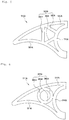
- FIGS. 3 and 4 are front views illustrating states in which a filler 800 according to an embodiment of the present invention is rotated to be closed or opened.
- the filler 800 includes a frame part 810 having a first frame part 810A and a second frame part 810B which are symmetrical with each other, a rotating part 805 connecting the first frame part 810A and the second frame part 810B, cut parts 842 and 844 dividing the frame part 810 into the first frame part 810A and the second frame part 810B; and is opened or closed by being rotated by a predetermined angle with respect to the rotating part 805.
- the first frame part 810A and the second frame part 810B may be each formed in a circular arc shape, and may include outer frame parts 812A and 812B facing the protective layer 710, inner frame parts 814A and 814B facing the core part 300, and support parts 820A and 820B connecting the outer frame parts 812A and 812B and the inner frame parts 814A and 814B.
- the frame part 810 includes an outer frame part 812 having a circular arc shape corresponding to a predetermined radius to maintain the roundness of the multicore cable 2000, and an inner frame part 814 including a core part accommodating part 815 configured to accommodate at least a portion of an outer circumference of the core part 300.
- the frame part 810 is divided into the first frame part 810A and the second frame part 810B by the upper cut part 842 of the outer frame part and the lower cut part 844 of the inner frame part 814, and is opened or closed by rotating the first frame part 810A and the second frame part 810B by the predetermined angle with respect to the rotating part 805. Accordingly, in the multicore cable 2000, optical units 100 which will be described below may be formed in the frame part 810.
- the outer frame part 812 may be designed to have a circular arc shape corresponding to the predetermined radius so as to maintain the roundness of the multicore cable 2000, and is completely divided by the upper cut part 842 into the first outer frame part 812A of the first frame part 810A and the second outer frame part 812B of the second frame part 810B.
- One end of the first outer frame part 812Aand one end of the second outer frame part 812B may be respectively connected to the first inner frame part 814A and the second inner frame part 814B which will be described in detail below.
- the inner frame part 814 is formed to face the core parts 300 and includes the core part accommodating part 815 which is in contact with at least a portion of the outer circumference of the core part 300.
- the inner frame part 814 is divided by the lower cut part 844 into the first inner frame part 814A of the first frame part 810A and the second inner frame part 814B of the second frame part 810B.
- the first inner frame part 814A and the second inner frame part 814B may respectively include a first core part accommodating part 815A and a second core part accommodating part 815B configured to accommodate at least a portion of the outer circumference of one of the core parts 300.
- the core part accommodating part 815 may be designed to have a shape corresponding to an external diameter of the core part 300 so that an external force applied to the multicore cable 2000 may not be concentrated on portions of the core parts 300 but be evenly dispersed.
- the rotating part 805 may be formed at a lower end of the inner frame part 814 such that the frame part 810 is rotated to be opened or closed. That is, the rotating part 805 may be formed at an inner side of the inner frame part 814 in a radial direction of the multicore cable 2000. In this case, a portion of the inner frame part 814 is cut by the lower cut part 844 and a non-cut portion thereof may serve as the rotating part 805. Alternatively, the inner frame part 814 may be completely cut by the lower cut part 844 and an additional rotating part (not shown) may be formed.
- the frame part 810 when the portion of the inner frame part 814 which is not cut by the lower cut part 844 serves as the rotating part 805, the frame part 810 may be manufactured using synthetic resin having a certain degree of elasticity or the like.
- the first frame part 810A and the second frame part 810B are rotated about the rotating part 805 in opposite directions and the frame part 810 is thus opened when an additional rotation axis for rotating the first frame part 810A and the second frame part 810B is not provided and the portion of the inner frame part 814 serves as a rotating part and applies a certain degree of external force to opposite sides of the first frame part 810A and the second frame part 810B.
- the fillers 800 has a rotatable structure and thus the core parts 300 and the fillers 800 may be easily combined during the manufacture of the multicore cable 2000. That is, when a plurality of opened fillers 800 and a number of core parts 300 corresponding thereto are combined at certain pitches as illustrated in FIG. 4 , the fillers 800 are closed by a force forming the core parts 300 at the certain pitches and the core parts 300 are placed at the core part accommodating part 815 as illustrated in FIG. 3 . Furthermore, since each of the fillers 800 includes the outer frame part 812 having the circular arc shape, a multicore cable having higher roundness may be manufactured.
- the multicore cable 2000 may be an optical fiber and power line composite cable having the optical units 100.
- each of the fillers 800 includes the optical unit accommodating part frames 840A and 840B and the optical unit accommodating part 840 formed at inner sides of the optical unit accommodating part frames 840A and 840B and may thus accommodate the optical unit 100 in the optical unit accommodating part 840.
- the optical unit accommodating part 840 may be located at a center of an inner side of the frame part 810 and be thus surrounded by the first optical unit accommodating part frame 840A provided at one end of the first frame part 810A and the second optical unit accommodating part frame 840B provided at one end of the second frame part 810B.
- the optical unit accommodating part 840 surrounded by the first optical unit accommodating part frame 840A and the second optical unit accommodating part frame 840B may have a round shape such that the optical unit 100 may be conveniently accommodated.
- the optical unit accommodating part 840 has a round shape as described above, the optical unit accommodating part 840 has a diameter greater than or equal to an external diameter of the optical unit 100 and thus the optical unit 100 may be prevented from being damaged due to the optical unit accommodating part frames 840A and 840B.
- the round shape is merely an example and the optical unit accommodating part 840 may be embodied in various shapes. In this case, a minor axis of the optical unit accommodating part 840 may have a diameter greater than or equal to the external diameter of the optical unit 100.
- the optical unit 100 When the optical unit 100 is accommodated and inserted into the optical unit accommodating part 840 and the first frame part 810A and the second frame part 810B are rotated to open the frame part 810, end parts of the first and second optical unit accommodating part frames 840A and 840B provided at the ends of the first outer frame part 812A and the second outer frame part 812B are separated from each other and thus the optical unit accommodating part 840 is opened.
- the optical unit 100 may be inserted into an inner side of the optical unit accommodating part 840.
- the optical unit 100 is provided between the separated end parts of the first optical unit accommodating part frame 840A and the second optical unit accommodating part frame 840B of the filler 800 with the opened frame part 810 as illustrated in FIG. 4 and is then placed at the optical unit accommodating part 840, and thereafter the filler 800 is closed by a force forming the certain pitches as illustrated in FIG. 3 .
- a length L of the lower cut part 844 may be determined to be equal to or less than half an internal diameter of the optical unit accommodating part 840, and preferably, a diameter D of the optical unit 100 accommodated in the optical unit accommodating part 840 (here, L ⁇ D/2). This is because, if the length L of the lower cut part 844 is greater than half the diameter D of the optical unit 100, the optical unit 100 accommodated in the optical unit accommodating part 840 may be caught between adjacent lower cut parts 844 when the first frame part 810A and the second frame part 810B are rotated to close the frame part 810.
- a length of the upper cut part 842 may be determined to be equal to or less than half the internal diameter of the optical unit accommodating part 840, and preferably, half the diameter D of the optical unit 100 (here, L ⁇ D/2).
- the optical unit 100 may be prevented from being damaged by being caught between the end parts of the optical unit accommodating part frames 840A and 840B, since the length of the upper cut part 842 is determined to be equal to or less than half the diameter D of the optical unit 100 (here, L ⁇ D/2).
- first frame part 810A and the second frame part 810B respectively include the first support part 820A and the second support part 820B
- the strength of the frame part 810 may be reinforced and an external force applied to the outer frame parts 812A and 812B may be dispersed to other portions of the filler 800.
- the support parts 820A and 820B may include a first frame support part 821A and a second frame support part 821B.
- the outer frame parts 812A and 812B and the inner frame parts 814A and 814B may be connected to each other.
- the support parts 820A and 820B may further include a first accommodating part support part 822A and a second accommodating part support part 822B configured to connect the frame part 810, the frame support parts 821A and 821B, and the optical unit accommodating part frames 840A and 840B.
- at least portions of the support parts 820A and 820B may connect the frame part 810 and the optical unit accommodating part 840.
- the first support part 820A may include the first frame support part 821A provided between the outer and inner frame parts 812 and 814 to connect the outer and inner frame parts 812 and 814, and the first accommodating part support part 822A connecting and supporting the first frame support part 821A and the optical unit accommodating part 840.
- the first frame support part 821A is provided between the outer frame part 812 and the inner frame part 814 to support the outer frame part 812 and the inner frame part 814, and provides bearing power when lateral pressure is applied to the multicore cable 2000 as described above with reference to FIGS. 2 and 3 . Furthermore, the first accommodating part support part 822A is configured to support the optical unit accommodating part 840 and the first frame support part 821A by connecting roughly center portions of the optical unit accommodating part 840 and the first frame support part 821A.
- the first accommodating part support part 822A is formed to taper from the frame support parts 821A and 821B toward the optical unit accommodating part frames 840A and 840B, and may thus minimize deformation of the optical unit accommodating part 840 to protect the optical unit 100 and prevent the filler 800 from being damaged and broken when lateral pressure or the like is applied the multicore cable 2000.
- the second frame support part 821B and the second accommodating part support part 822B of the second support part 820B are symmetric with respect to the first frame support part 821A and the first accommodating part support part 822A of the first support part 820A.
- the first frame support part 821A and the first accommodating part support part 822A are substantially the same as the first frame support part 821A and the first accommodating part support part 822A and thus are not redundantly described here.
- FIG. 5 is a diagram illustrating only a first frame part 1810A of the filler 800, according to another embodiment.
- the first frame part 1810A of the filler 800 is substantially the same as that in the previous embodiment, in that the first frame part 1810A includes a first outer frame part 1812A, a first inner frame part 1814A, and a first optical unit accommodating part 1840A but is different from that in the previous embodiment in terms of a structure of a support part at an inner side of the frame part 810.
- the first support part 1820A of the first frame part 1810A includes a first frame support part 1821A provided between the first outer frame part 1812A and the first inner frame part 1814A to connect the first outer frame part 1812A and the first inner frame part 1814A, a first accommodating part support part 1822A connecting and supporting the first outer frame part 1812A and the first optical unit accommodating part 1840A, and a second accommodating part support part 1823A connecting and supporting the first inner frame part 1814A and the first optical unit accommodating part 1840A.
- the present embodiment is different from the previous embodiment, in that a plurality of accommodating part support parts supporting the first optical unit accommodating part 1840A are directly coupled to the first outer frame part 1812A and the first inner frame part 1814A.
- the second frame part 810B has a structure symmetrical to that of the first frame part 1810A and is thus not described again here.
- FIG. 6 is a diagram illustrating only a first frame part 1810A of a filler according to another embodiment.
- a first frame part 2810A of a filler is substantially the same as that of the previous embodiment, in that the first frame part 2810A includes a first outer frame part 2812A, a first inner frame part 2814a, a first optical unit accommodating part frame 2840A, and a first support part 2820A but is different from that of the previous embodiment in terms of a shape of a first support part provided at an inner side of the first frame part 2810A.
- each of a first frame support part 2821A, a first accommodating part support part 2822A, and a second accommodating part support part 2823A is formed in a circular arc shape.
- an overall shape of the first support part 2820A is round, and the first frame part 2814a and the first optical unit accommodating part 2840A are connected and supported by the first support part 2820A.
- a second frame part (not shown) has a structure symmetrical to that of the first frame part 2810A and is thus not described again here.
- the filler 800 includes an accommodating part support part to connect the frame part, the frame support part, and the optical unit accommodating part frame.
- an accommodating part support part to connect the frame part, the frame support part, and the optical unit accommodating part frame.
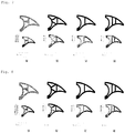
- FIG. 7 is a diagram comparing degrees of deflection of fillers according to examples of the present invention with those of fillers according to comparative examples when a certain degree of lateral pressure, e.g., 5 ton/m, was applied thereto.
- a illustrates the structure of the filler of FIG. 3
- (b) illustrates the structure of the filler of FIG. 5 .
- (c) illustrates comparative example 1 in which a support part does not include an accommodating part support part connected to an optical unit accommodating part and simply includes only a single frame support part.
- (d) illustrates comparative example 2 in which a support part does not include an accommodating part support part connected to an optical unit accommodating part and simply includes only two frame support parts.
- degrees of deformation of the fillers according to examples 1 and 2 of the present invention were respectively 0.94 mm and 0.69 mm and thus were very satisfactory.
- degrees of deformation of the fillers according to comparative examples 1 and 2 were respectively 3.13 mm and 2.37 mm and were relatively very high.
- FIG. 8 is a diagram illustrating peak stresses of fillers according to examples of the present invention and those of fillers according to comparative examples when the same lateral pressure as that of FIG. 7 was applied thereto.
- peak stresses of the fillers according to examples 1 and 2 of the present invention were respectively 34, 7 MPa and 38.3 MPa, and peak stresses of the fillers according to comparative examples 1 and 2 were respectively 60.3 MPa and 50.2 MPa. Accordingly, the peak stresses of the fillers of examples 1 and 2 were lower than those of the fillers of comparative examples 1 and 2.
- the optical unit accommodating part frames 840A and 840B may be formed at one end of the outer frame part 812A and one end of the outer frame part 812B, other ends of the outer frame parts 812A and 812B may be connected to the inner frame parts 814A and 814B, the frame support parts 821A and 821B may be formed between the one ends and the other ends of the outer frame parts 812A and 812B, and a length to the one ends from the locations of the frame support parts 821A and 821B may be shorter than a length to the other ends from the locations of the frame support parts 821A and 821B.
- one end of the optical unit accommodating part frame 840A and one end of the optical unit accommodating part frame 840B may be connected to the outer frame parts 812A and 812B, other ends of the optical unit accommodating part frames 840A and 840B may be connected to the inner frame part 814, the accommodating part support parts 822A and 822B may be connected between the one ends and the other ends of the optical unit accommodating part frames 840A and 840B, and a length to the one ends from the locations of the accommodating part support parts 822A and 822B may be shorter than a length to the other ends from the locations of the accommodating part support parts 822A and 822B.
- an external force applied to the multicore cable 2000 may be efficiently dispersed to the fillers 800 and thus deformation of the fillers 800 may be minimized, thereby maintaining the roundness of the multicore cable 2000, protecting the optical units 100, and preventing the fillers 800 from being damaged and broken.
Landscapes
- Physics & Mathematics (AREA)
- Engineering & Computer Science (AREA)
- Manufacturing & Machinery (AREA)
- General Physics & Mathematics (AREA)
- Optics & Photonics (AREA)
- Communication Cables (AREA)
- Light Guides In General And Applications Therefor (AREA)
- Insulated Conductors (AREA)
Abstract
Description
- The present invention relates to a filler and a multicore cable having the same.
- In a multicore cable with a plurality of power line units each having a conductor to transmit power (hereinafter referred to as 'core parts'), the core parts are arranged to be almost symmetric with respect to a center portion of the multicore cable and a protective layer is provided along outer surfaces of the core parts.
- However, since the multicore cable includes the core parts, the roundness of the multicore cable may be difficult to maintain. In particular, when the multicore cable is installed or is wound about a turntable to install it under the sea, an external force such as lateral pressure may be applied thereto and thus the core parts included in the multicore part may be damaged. Thus, a filler is necessary to maintain the roundness of the multicore cable and protect the core parts included in the multicore part when the multicore cable is installed or when an external force such as lateral pressure is applied to the multicore part.
- Recently, there is a growing need for an optical communication system based on an optical cable with optical fibers having high bandwidth characteristics than those of an existing copper communication line. Thus, generally, power cables for power transmission are manufactured in the form of a composite cable with optical units having optical fibers to simultaneously transmit power and information.
- An optical cable with optical fibers is more advantageous than an existing copper line in terms of low loss characteristics, transmission characteristics such as a high bandwidth, etc., but has lower mechanical strength than a copper line and is thus a transmission medium having low mechanical reliability. Actually, a failure (disconnection, bending, or the like) may occur due to mechanical vulnerability of the optical fiber and various internal/external causes.
- Accordingly, when the filler is provided, not only the above-described function but also a function of accommodating and protecting the optical unit are needed.
- To address the above-described problem, the present invention is directed to a filler for maintaining the roundness of a multicore cable having a plurality of core parts.
- The present invention is also directed to a filler for accommodating and protecting an optical unit when a multicore cable is manufactured in the form of a composite cable having the optical unit.
- The present invention is also directed to a filler for preventing damage to core parts and an optical unit included in a multicore cable when the multicore cable is installed or when an external force such as lateral pressure is applied to the multicore cable.
- According to an aspect of the present invention, there is provided a filler which is disposed between a core part and a protective layer of a multicore cable having a plurality of the core parts and the protective layer surrounding the plurality of core parts, wherein each the core part comprises a conductor, an inner semiconducting layer, an insulating layer, an outer semiconducting layer, a metal sheath and a polymeric sheath, the filler comprising: a frame part including a first frame part and a second frame part which are symmetric to each other; a rotating part configured to connect the first frame part and the second frame part; and a cut part dividing the frame part into the first frame part and the second frame part, wherein the filler is opened or closed by being rotated by a certain angle about the rotating part, and each of the first frame part and the second frame part comprises: an outer frame part formed in a circular arc shape; an inner frame part; and a support part configured to connect the outer frame part and the inner frame part.
- According to another aspect of the present invention, there is provided the filler, further comprising: optical unit accommodating part frames respectively formed at the first frame part and the second frame part; and an optical unit accommodating part configured to be opened or closed as the filler is rotated about the rotating part.
- According to other aspect of the present invention, there is provided the filler, wherein the cut part comprises: an upper cut part formed at the outer frame part; and a lower cut part formed at the inner frame part, wherein a length of the lower cut part is equal to or less than half an internal diameter of the optical unit accommodating part.
- According to other aspect of the present invention, there is provided The filler of claim 3, wherein a length of the upper cut part is equal to or less than half the internal diameter of the optical unit accommodating part.
- According to other aspect of the present invention, there is provided the filler, wherein at least a portion of the support part connects the frame part and the optical unit accommodating part.
- According to other aspect of the present invention, there is provided the filler, wherein the support part comprises: a frame support part configured to connect the outer frame part and the inner frame part; and an accommodating part support part configured to connect and support the optical unit accommodating part frames and the frame support part.
- According to other aspect of the present invention, there is provided the filler, wherein the accommodating part support part tapers from the frame support part toward the optical unit accommodating part frames.
- According to other aspect of the present invention, there is provided the filler, wherein one end of the outer frame part is connected to the optical unit accommodating part and another end thereof is connected to the inner frame part, the frame support part is formed between the one end and the other end of the outer frame part, and a length from a location of the frame support part to the one end is shorter than a length from the location of the frame support part to the other end.
- According to other aspect of the present invention, there is provided the filler, wherein one end of the optical unit accommodating part frame is connected to the outer frame part and another end thereof is connected to the inner frame part, the accommodating part support part is formed between the one end and the other end of the optical unit accommodating part frame, and a length from a location of the accommodating part support part to the one end is shorter than a length from the location of the accommodating part support part to the other end.
- According to other aspect of the present invention, there is provided a multicore cable which includes a plurality of core parts, a protective layer surrounding the plurality of core parts and a filler disposed between the core part and the protective layer, wherein each the core part comprises a conductor, an inner semiconducting layer, an insulating layer, an outer semiconducting layer, a metal sheath and a polymeric sheath, the filler comprising: a frame part including a first frame part and a second frame part which are symmetric to each other; a rotating part configured to connect the first frame part and the second frame part; and a cut part dividing the frame part into the first frame part and the second frame part, wherein the filler is opened or closed by being rotated by a certain angle about the rotating part, and each of the first frame part and the second frame part comprises: an outer frame part formed in a circular arc shape, and facing the protective layer; an inner frame part facing the core part; and a support part configured to connect the outer frame part and the inner frame part.
- According to other aspect of the present invention, there is provided the multicore cable, wherein each of the fillers further comprises: optical unit accommodating part frames respectively formed at the first frame part and the second frame part; and an optical unit accommodating part configured to be opened or closed as the filler is rotated about the rotating part.
- According to other aspect of the present invention, there is provided the multicore cable, wherein an optical unit is accommodated in the optical unit accommodating part, and an internal diameter of the optical unit accommodating part is greater than or equal to an external diameter of the optical unit.
- According to other aspect of the present invention, there is provided the multicore cable, wherein the cut part comprises: an upper cut part formed at an outer side of the optical unit accommodating part in a radial direction of the multicore cable; and a lower cut part formed at an inner side of the optical unit accommodating part in the radial direction of the multicore cable, wherein a length of the lower cut part is equal to or less than half an external diameter of the optical unit.
- According to other aspect of the present invention, there is provided the multicore cable, wherein a length of the upper cut part is equal to or less than half the external diameter of the optical unit.
- According to other aspect of the present invention, there is provided the multicore cable, wherein at least a portion of the support part connects the frame part and the optical unit accommodating part.
- According to other aspect of the present invention, there is provided the multicore cable, wherein the support part comprises: a frame support part configured to connect and support the outer frame part and the inner frame part; and an accommodating part support part configured to connect and support the optical unit accommodating part frames and the frame support part.
- According to other aspect of the present invention, there is provided the multicore cable, wherein the accommodating part support part tapers from the frame support part toward the optical unit accommodating part frames.
- According to other aspect of the present invention, there is provided the multicore cable, wherein one end of the outer frame part is connected to the optical unit accommodating part and another end thereof is connected to the inner frame part, the frame support part is formed between the one end and the other end of the outer frame part, and a length from a location of the frame support part to the one end is shorter than a length from the location of the frame support part to the other end.
- According to other aspect of the present invention, there is provided the multicore cable, wherein one end of the optical unit accommodating part frame is connected to the outer frame part and another end thereof is connected to the inner frame part, the accommodating part support part is formed between the one end and the other end of the optical unit accommodating part frame, and a length from a location of the accommodating part support part to the one end is shorter than a length from the location of the accommodating part support part to the other end.
- According to the present invention, the roundness of a multicore cable with a plurality of core parts can be maintained using a filler provided between the core parts and an external protective layer.
- When the multicore cable is manufactured in the form of a composite cable having an optical unit, the filler can accommodate and protect the optical unit.
- Furthermore, the core parts and the optical unit included in multicore cable can be prevented from being damaged due to the filler when the multicore cable is installed or when an external force such as lateral pressure is applied to the multicore cable.
-
-
FIG. 1 is a cross-sectional view of a multicore cable in the form of an optical composite cable having an optical fiber unit, according to the related art, -
FIG. 2 is a cross-sectional view of a multicore cable having a filler according to an embodiment of the present invention, -
FIG. 3 is a front view of a filler according to an embodiment of the present invention, -
FIG. 4 is a front view illustrating a state in which the filler ofFIG. 3 is rotated and cut, -
FIGS. 5 and 6 are diagrams illustrating structures of fillers according to various embodiments of the present invention, -
FIG. 7 is a diagram comparing degrees of deflection of fillers according to examples of the present invention with those of fillers according to comparative examples, and -
FIG. 8 is a diagram comparing peak stresses of fillers according to examples of the present invention with those of fillers according to comparative examples. - Hereinafter, various embodiments of the present invention will be described in detail. As used herein, the term 'multicore cable' is defined as a cable with a plurality of power line units (hereinafter referred to as 'core parts') each having a conductor, an inner semiconducting layer, an insulating layer, and an outer semiconducting layer and configured to transmit power. First, a structure of a multicore cable which is in the form of an optical fiber and power line composite cable having an optical unit will be described. Next, a filler according to the present invention will be described.
-
FIG. 1 is a cross-sectional view of amulticore cable 1000 in the form of an optical fiber and power line composite cable withoptical units 100, according to the related art. - Although
FIG. 1 illustrates themulticore cable 1000 which is a three-phase cable having threecore parts 300 as an example, themulticore cable 1000 is not limited thereto and is applicable to all multicore cables having a plurality of core parts. - Each of the
core parts 300 includes aconductor 310, an innersemiconducting layer 330, aninsulating layer 320, an outersemiconducting layer 340, ametal sheath 350, and a polymeric sheath 360. - The
conductor 310 functions as a path through which current flows to transmit power, and may be formed of a material, e.g., copper or aluminum, having high conductivity to minimize power loss and having strength and flexibility appropriate to manufacture and use a cable. - The
conductor 310 may be a round compressed conductor compressed into a round shape by twisting a plurality of round wires or may be a flat conductor including a round center wire and a flat wire layer having flat wires twisted to surround the round center wire, and having an overall round cross section. The flat conductor has a relatively high space factor and may thus contribute to decreasing an external diameter of a cable, when compared to the compressed round conductor. - However, since the
conductor 310 has a non-flat surface, an electric field may not be uniform and a corona discharge may partially occur. Furthermore, the insulating performance of theconductor 310 may be decreased when a gap occurs between a surface of theconductor 310 and theinsulating layer 320 which will be described in detail below. - To address the above-described problems, the inner
semiconducting layer 330 may be formed outside theconductor 310. The innersemiconducting layer 330 may be formed by adding conductive particles, such as carbon black, carbon nanotubes, carbon nanoplates, or graphite, to an insulating material and may thus have a semiconducting property. - The inner
semiconducting layer 330 prevents a sharp change in an electric field between theconductor 310 and theinsulating layer 320 which will be described in detail below, thereby stabilizing insulating performance. Theinner semiconducting layer 330 may also suppress a non-uniform charge distribution on a surface of theconductor 310 to uniformize an electric field, and prevent a gap from being formed between theconductor 310 and theinsulating layer 320, thereby suppressing the occurrence of a corona discharge, a dielectric breakdown, etc. - The insulating
layer 320 is provided on an outermost side of the innersemiconducting layer 330 to electrically insulate theconductor 310 so that electric current may not leak to the outside via theconductor 310. Generally, the insulatinglayer 320 should have a high breakdown voltage and insulating performance thereof should be maintained for a long time period. Furthermore, the insulatinglayer 320 should have a low dielectric loss rate and heat resistance performance, e.g., a heat resistance property. Accordingly, the insulatinglayer 320 may be formed of polyolefin resin such as polyethylene and polypropylene, and preferably, polyethylene resin. Here, the polyethylene resin may be crosslinked resin. - The outer
semiconducting layer 340 may be provided outside the insulatinglayer 320. The outersemiconducting layer 340 is formed of a semiconducting material obtained by adding conductive particles, e.g., carbon black, carbon nanotubes, carbon nanoplates, or graphite, to an insulating material, similar to the innersemiconducting layer 330, and may suppress a non-uniform charge distribution between the insulatinglayer 320 an themetal sheath 350, thereby stabilizing insulating performance. In addition, the outersemiconducting layer 340 may planarize a surface of the insulatinglayer 320 to lessen the concentration of an electric field, thereby preventing the occurrence of a corona discharge, and may physically protect the insulatinglayer 320. - Each of the
core parts 300 may additionally include a moisture absorbing part (not shown) to prevent the permeation of moisture into themulticore cable 1000. The moisture absorbing part may be formed between the wires of theconductor 310 and/or on an outer surface of theconductor 310. The moisture absorbing part may be in the form of powder, a tape, a coating layer, or a film containing a super-absorbent polymer (SAP) which quickly absorbs moisture permeating themulticore cable 1000 and is more capable of maintaining a state of absorbing the moisture, and may prevent the permeation of moisture in a lengthwise direction of themulticore cable 1000. The moisture absorbing part may have a semiconducting property to prevent a sharp change in an electric field. - The
metal sheath 350 and the polymeric sheath 360 may be additionally provided outside the outersemiconducting layer 340. Themetal sheath 350 and the polymeric sheath 360 may protect thecore part 300 of themulticore cable 1000 from various environmental causes, e.g., the permeation of moisture, mechanical trauma, abrasion, etc., and fault current which may affect the power transmission performance of themulticore cable 1000. - The
metal sheath 350 may be grounded at an end part of themulticore cable 1000, function as a path through which fault current flows when a fault such as a ground fault or a short circuit occurs, protect themulticore cable 1000 from the outside, and block an electric field from being discharged to the outside of themulticore cable 1000. - When a cable is installed in an environment, e.g. , at a bottom of a sea, the
metal sheath 350 may be formed to seal thecore part 300, thereby preventing a decrease in insulating performance, caused by the invasion of foreign substances such as moisture. For example, a cable having seamless and consecutive outer surfaces may be manufactured by extruding a metal fused on outer surfaces of thecore parts 300, thereby improving water resistance. The metal may be lead or aluminum. In particular, in the case of a submarine cable, lead having high corrosion resistance to sea water is preferably used, and a metal element-added lead alloy is more preferably used to supplement a mechanical property. - The polymeric sheath 360 formed of resin such as polyvinyl chloride (PVC) or polyethylene may be provided on an outer side of the
metal sheath 350 to improve the corrosion resistance, water resistance, etc. of themulticore cable 1000 and protect themulticore cable 1000 from mechanical trauma and other external and environmental causes such as heat, ultraviolet light, etc. In particular, polyethylene resin having high water resistance is preferably used for a power cable installed at a bottom of a sea, and polyvinyl chloride resin is more preferably used in an environment requiring frame resistance. - Furthermore, the
core part 300 may further include a woven copper wire tape (not shown) and a moisture absorbing layer (not shown) between themetal sheath 350 and the outersemiconducting layer 340. The woven copper wire tape may include copper wire, a non-woven fabric tape, etc., and be configured to facilitate an electrical contact between the outersemiconducting layer 340 and the metal sheath 218. The moisture absorbing layer may be in the form of powder, a tape, a coating layer, a film, or the like containing SAP which quickly absorbs moisture permeating themulticore cable 1000 and is more capable of maintaining a state of absorbing the moisture. Thus, the moisture absorbing layer may prevent the permeation of moisture in the lengthwise direction of themulticore cable 1000. To prevent a sharp change in an electric field in the moisture absorbing layer, a copper wire may be included in the moisture absorbing layer. - When the
multicore cable 1000 is in the form of an optical fiber and power line composite cable, themulticore cable 1000 may further include theoptical units 100. - Here, the
optical unit 100 may include at least oneoptical fiber 111 and atube 112 accommodating the at least oneoptical fiber 111. - Each of the
optical units 100 includes a predetermined number ofoptical fibers 111 mounted in thetube 112, together with a fillingmaterial 113. Thetube 112 may be formed of a material having hardness, such as stainless steel. Each of theoptical units 100 may further include asheath 130 covering thetube 112. - The
multicore cable 1000 may include various types ofprotective layer 710 to protect internal components thereof. For example, as illustrated inFIG. 1 , themulticore cable 1000 may include abedding layer 700 covering thecore parts 300 and theoptical units 100 and formed of polypropylene (PP) yarn or the like, and ajacket 720. Themulticore cable 1000 may further include a fillingmaterial 400 to protect thecore parts 300 and theoptical units 100 included in thebedding layer 700. Although not shown, when themulticore cable 1000 is a submarine cable installed to cross a bottom of a sea, themulticore cable 1000 may further include a plurality of armoring iron wires at an outer side of thebedding layer 700 to improve mechanical strength thebedding layer 700. - In the
multicore cable 1000 configured as described above, the fillingmaterial 400 may be formed of polypropylene yarn. However, when a plurality of yarns are arranged in a core as described above, the yarns may be caught by equipment used to combine thecore parts 300, theoptical units 100, and the yarns at certain pitches to form the cable. To solve this problem, the combining of thecore parts 300, theoptical units 100, and the yarns is performed by decreasing the number of yarns to be inserted into the cable but a region of the cable may be distorted due to pressure applied during formation of a protective layer and thus a whole cross section of the cable may not be round. As described above, when the cross section of the cable is not round, a load of the cable wound along a turntable after the production of the cable is not uniformly dispersed. Thus, the cable is likely to be broken during storage or transfer thereof, and a tensile force applied when the cable is bent during installation of the cable is not uniformly applied to all cross sections of the cable. Such a phenomenon will be a cause for damage to a portion of the cable to which a higher tensile force is applied when the cable is used for a long period time. Furthermore, in the case of an optical fiber and power line composite cable including theoptical units 100, theoptical units 100 are likely to be damaged when an external force is applied to the cable. - Accordingly, the
core parts 300 and theoptical units 100 of themulticore cable 1000 should be prevented from being damaged or broken by uniformly dispersing bending stress, installation tension, or a tensile force to be applied to themulticore cable 1000 the during installation of themulticore cable 1000 while maintaining the roundness of themulticore cable 1000. -
FIGS. 2 to 4 are cross-sectional views illustrating the structures offillers 800 and amulticore cable 2000 including the same, according to an embodiment of the present invention. The same reference numerals are allocated to components ofFIG. 2 that are the same as those ofFIG. 1 . Themulticore cable 2000 is different from themulticore cable 1000 ofFIG. 1 in terms of thefillers 800, and will be described below while focusing on the differences from themulticore cable 1000. - Referring to
FIG. 2 , in themulticore cable 2000 with a plurality ofcore parts 300, each of thefillers 800 may be provided between one of thecore parts 300 and theprotective layer 710. Thefillers 800 may maintain the roundness of themulticore cable 2000, and accommodate and protectoptical units 100 when themulticore cable 2000 is in the form of an optical fiber and power line composite cable having theoptical units 100. Furthermore, when themulticore cable 2000 is installed or when an external force such as lateral pressure is applied to themulticore cable 2000, thefillers 800 may prevent damage to thecore parts 300 and theoptical units 100 included in thefillers 800. - A structure of the
fillers 800 will be described in detail below. -
FIGS. 3 and 4 are front views illustrating states in which afiller 800 according to an embodiment of the present invention is rotated to be closed or opened. - Referring to
FIGS. 3 and 4 , thefiller 800 includes a frame part 810 having afirst frame part 810A and asecond frame part 810B which are symmetrical with each other, arotating part 805 connecting thefirst frame part 810A and thesecond frame part 810B, cutparts first frame part 810A and thesecond frame part 810B; and is opened or closed by being rotated by a predetermined angle with respect to therotating part 805. Thefirst frame part 810A and thesecond frame part 810B may be each formed in a circular arc shape, and may includeouter frame parts protective layer 710,inner frame parts core part 300, andsupport parts outer frame parts inner frame parts - In detail, the frame part 810 includes an outer frame part 812 having a circular arc shape corresponding to a predetermined radius to maintain the roundness of the
multicore cable 2000, and an inner frame part 814 including a core part accommodating part 815 configured to accommodate at least a portion of an outer circumference of thecore part 300. The frame part 810 is divided into thefirst frame part 810A and thesecond frame part 810B by theupper cut part 842 of the outer frame part and thelower cut part 844 of the inner frame part 814, and is opened or closed by rotating thefirst frame part 810A and thesecond frame part 810B by the predetermined angle with respect to therotating part 805. Accordingly, in themulticore cable 2000,optical units 100 which will be described below may be formed in the frame part 810. - The outer frame part 812 may be designed to have a circular arc shape corresponding to the predetermined radius so as to maintain the roundness of the
multicore cable 2000, and is completely divided by theupper cut part 842 into the firstouter frame part 812A of thefirst frame part 810A and the secondouter frame part 812B of thesecond frame part 810B. One end of the first outer frame part 812Aand one end of the secondouter frame part 812B may be respectively connected to the firstinner frame part 814A and the secondinner frame part 814B which will be described in detail below. - In the
multicore cable 2000, the inner frame part 814 is formed to face thecore parts 300 and includes the core part accommodating part 815 which is in contact with at least a portion of the outer circumference of thecore part 300. In this case, at least a portion of the inner frame part 814 is divided by thelower cut part 844 into the firstinner frame part 814A of thefirst frame part 810A and the secondinner frame part 814B of thesecond frame part 810B. The firstinner frame part 814A and the secondinner frame part 814B may respectively include a first corepart accommodating part 815A and a second corepart accommodating part 815B configured to accommodate at least a portion of the outer circumference of one of thecore parts 300. For example, the core part accommodating part 815 may be designed to have a shape corresponding to an external diameter of thecore part 300 so that an external force applied to themulticore cable 2000 may not be concentrated on portions of thecore parts 300 but be evenly dispersed. - The
rotating part 805 may be formed at a lower end of the inner frame part 814 such that the frame part 810 is rotated to be opened or closed. That is, therotating part 805 may be formed at an inner side of the inner frame part 814 in a radial direction of themulticore cable 2000. In this case, a portion of the inner frame part 814 is cut by thelower cut part 844 and a non-cut portion thereof may serve as therotating part 805. Alternatively, the inner frame part 814 may be completely cut by thelower cut part 844 and an additional rotating part (not shown) may be formed. - As illustrated in
FIGS. 3 and 4 , when the portion of the inner frame part 814 which is not cut by thelower cut part 844 serves as therotating part 805, the frame part 810 may be manufactured using synthetic resin having a certain degree of elasticity or the like. Thefirst frame part 810A and thesecond frame part 810B are rotated about therotating part 805 in opposite directions and the frame part 810 is thus opened when an additional rotation axis for rotating thefirst frame part 810A and thesecond frame part 810B is not provided and the portion of the inner frame part 814 serves as a rotating part and applies a certain degree of external force to opposite sides of thefirst frame part 810A and thesecond frame part 810B. - As described above, the
fillers 800 according to an embodiment of the present invention has a rotatable structure and thus thecore parts 300 and thefillers 800 may be easily combined during the manufacture of themulticore cable 2000. That is, when a plurality of openedfillers 800 and a number ofcore parts 300 corresponding thereto are combined at certain pitches as illustrated inFIG. 4 , thefillers 800 are closed by a force forming thecore parts 300 at the certain pitches and thecore parts 300 are placed at the core part accommodating part 815 as illustrated inFIG. 3 . Furthermore, since each of thefillers 800 includes the outer frame part 812 having the circular arc shape, a multicore cable having higher roundness may be manufactured. - The
multicore cable 2000 may be an optical fiber and power line composite cable having theoptical units 100. In this case, each of thefillers 800 includes the optical unit accommodating part frames 840A and 840B and the opticalunit accommodating part 840 formed at inner sides of the optical unit accommodating part frames 840A and 840B and may thus accommodate theoptical unit 100 in the opticalunit accommodating part 840. - The optical
unit accommodating part 840 may be located at a center of an inner side of the frame part 810 and be thus surrounded by the first optical unit accommodatingpart frame 840A provided at one end of thefirst frame part 810A and the second optical unit accommodatingpart frame 840B provided at one end of thesecond frame part 810B. - When the
first frame part 810A and thesecond frame part 810B are rotated to close the frame part 810, the opticalunit accommodating part 840 surrounded by the first optical unit accommodatingpart frame 840A and the second optical unit accommodatingpart frame 840B may have a round shape such that theoptical unit 100 may be conveniently accommodated. When the opticalunit accommodating part 840 has a round shape as described above, the opticalunit accommodating part 840 has a diameter greater than or equal to an external diameter of theoptical unit 100 and thus theoptical unit 100 may be prevented from being damaged due to the optical unit accommodating part frames 840A and 840B. Here, the round shape is merely an example and the opticalunit accommodating part 840 may be embodied in various shapes. In this case, a minor axis of the opticalunit accommodating part 840 may have a diameter greater than or equal to the external diameter of theoptical unit 100. - When the
optical unit 100 is accommodated and inserted into the opticalunit accommodating part 840 and thefirst frame part 810A and thesecond frame part 810B are rotated to open the frame part 810, end parts of the first and second optical unit accommodating part frames 840A and 840B provided at the ends of the firstouter frame part 812A and the secondouter frame part 812B are separated from each other and thus the opticalunit accommodating part 840 is opened. Thus, theoptical unit 100 may be inserted into an inner side of the opticalunit accommodating part 840. - In detail, when the
multicore cable 2000 is manufactured by combining the number ofcore parts 300 and the number ofoptical units 100 corresponding to thefillers 800 at the certain pitches, theoptical unit 100 is provided between the separated end parts of the first optical unit accommodatingpart frame 840A and the second optical unit accommodatingpart frame 840B of thefiller 800 with the opened frame part 810 as illustrated inFIG. 4 and is then placed at the opticalunit accommodating part 840, and thereafter thefiller 800 is closed by a force forming the certain pitches as illustrated inFIG. 3 . - In this case, a length L of the
lower cut part 844 may be determined to be equal to or less than half an internal diameter of the opticalunit accommodating part 840, and preferably, a diameter D of theoptical unit 100 accommodated in the optical unit accommodating part 840 (here, L<D/2). This is because, if the length L of thelower cut part 844 is greater than half the diameter D of theoptical unit 100, theoptical unit 100 accommodated in the opticalunit accommodating part 840 may be caught between adjacentlower cut parts 844 when thefirst frame part 810A and thesecond frame part 810B are rotated to close the frame part 810. - Similarly, a length of the
upper cut part 842 may be determined to be equal to or less than half the internal diameter of the opticalunit accommodating part 840, and preferably, half the diameter D of the optical unit 100 (here, L<D/2). Thus, even if theoptical unit 100 provided in the opticalunit accommodating part 840 is located between end parts of the optical unit accommodating part frames 840A and 840B due to a process error, theoptical unit 100 may be prevented from being damaged by being caught between the end parts of the optical unit accommodating part frames 840A and 840B, since the length of theupper cut part 842 is determined to be equal to or less than half the diameter D of the optical unit 100 (here, L<D/2). - Since the
first frame part 810A and thesecond frame part 810B respectively include thefirst support part 820A and thesecond support part 820B, the strength of the frame part 810 may be reinforced and an external force applied to theouter frame parts filler 800. - The
support parts frame support part 821A and a secondframe support part 821B. Theouter frame parts inner frame parts support parts part support part 822A and a second accommodatingpart support part 822B configured to connect the frame part 810, theframe support parts support parts unit accommodating part 840. - For example, as illustrated in
FIGS. 3 and 4 , thefirst support part 820A may include the firstframe support part 821A provided between the outer and inner frame parts 812 and 814 to connect the outer and inner frame parts 812 and 814, and the first accommodatingpart support part 822A connecting and supporting the firstframe support part 821A and the opticalunit accommodating part 840. - The first
frame support part 821A is provided between the outer frame part 812 and the inner frame part 814 to support the outer frame part 812 and the inner frame part 814, and provides bearing power when lateral pressure is applied to themulticore cable 2000 as described above with reference toFIGS. 2 and3 . Furthermore, the first accommodatingpart support part 822A is configured to support the opticalunit accommodating part 840 and the firstframe support part 821A by connecting roughly center portions of the opticalunit accommodating part 840 and the firstframe support part 821A. The first accommodatingpart support part 822A is formed to taper from theframe support parts unit accommodating part 840 to protect theoptical unit 100 and prevent thefiller 800 from being damaged and broken when lateral pressure or the like is applied themulticore cable 2000. - In the
second frame part 810B, the secondframe support part 821B and the second accommodatingpart support part 822B of thesecond support part 820B are symmetric with respect to the firstframe support part 821A and the first accommodatingpart support part 822A of thefirst support part 820A. The firstframe support part 821A and the first accommodatingpart support part 822A are substantially the same as the firstframe support part 821A and the first accommodatingpart support part 822A and thus are not redundantly described here. -
FIG. 5 is a diagram illustrating only afirst frame part 1810A of thefiller 800, according to another embodiment. - Referring to
FIG. 5 , thefirst frame part 1810A of thefiller 800 according to the present embodiment is substantially the same as that in the previous embodiment, in that thefirst frame part 1810A includes a firstouter frame part 1812A, a firstinner frame part 1814A, and a first opticalunit accommodating part 1840A but is different from that in the previous embodiment in terms of a structure of a support part at an inner side of the frame part 810. - The
first support part 1820A of thefirst frame part 1810A includes a firstframe support part 1821A provided between the firstouter frame part 1812A and the firstinner frame part 1814A to connect the firstouter frame part 1812A and the firstinner frame part 1814A, a first accommodatingpart support part 1822A connecting and supporting the firstouter frame part 1812A and the first opticalunit accommodating part 1840A, and a second accommodatingpart support part 1823A connecting and supporting the firstinner frame part 1814A and the first opticalunit accommodating part 1840A. - The present embodiment is different from the previous embodiment, in that a plurality of accommodating part support parts supporting the first optical
unit accommodating part 1840A are directly coupled to the firstouter frame part 1812A and the firstinner frame part 1814A. - In the present embodiment, the
second frame part 810B has a structure symmetrical to that of thefirst frame part 1810A and is thus not described again here. -
FIG. 6 is a diagram illustrating only afirst frame part 1810A of a filler according to another embodiment. - Referring to
FIG. 6 , afirst frame part 2810A of a filler according to the present embodiment is substantially the same as that of the previous embodiment, in that thefirst frame part 2810A includes a firstouter frame part 2812A, a first inner frame part 2814a, a first optical unit accommodatingpart frame 2840A, and afirst support part 2820A but is different from that of the previous embodiment in terms of a shape of a first support part provided at an inner side of thefirst frame part 2810A. - In the
first support part 2820A, each of a firstframe support part 2821A, a first accommodatingpart support part 2822A, and a second accommodatingpart support part 2823A is formed in a circular arc shape. Thus, an overall shape of thefirst support part 2820A is round, and the first frame part 2814a and the first opticalunit accommodating part 2840A are connected and supported by thefirst support part 2820A. - In the present embodiment, a second frame part (not shown) has a structure symmetrical to that of the
first frame part 2810A and is thus not described again here. - As described above, the
filler 800 according to the present invention includes an accommodating part support part to connect the frame part, the frame support part, and the optical unit accommodating part frame. Thus, when lateral pressure or the like is applied to themulticore cable 2000, deformation of thefiller 800 may be minimized to protect theoptical units 100 and prevent thefiller 800 from being damaged and broken. -
FIG. 7 is a diagram comparing degrees of deflection of fillers according to examples of the present invention with those of fillers according to comparative examples when a certain degree of lateral pressure, e.g., 5 ton/m, was applied thereto. InFIG. 7 , (a) illustrates the structure of the filler ofFIG. 3 , and (b) illustrates the structure of the filler ofFIG. 5 . (c) illustrates comparative example 1 in which a support part does not include an accommodating part support part connected to an optical unit accommodating part and simply includes only a single frame support part. (d) illustrates comparative example 2 in which a support part does not include an accommodating part support part connected to an optical unit accommodating part and simply includes only two frame support parts. - Referring to
FIG. 7 , degrees of deformation of the fillers according to examples 1 and 2 of the present invention were respectively 0.94 mm and 0.69 mm and thus were very satisfactory. In contrast, degrees of deformation of the fillers according to comparative examples 1 and 2 were respectively 3.13 mm and 2.37 mm and were relatively very high. -
FIG. 8 is a diagram illustrating peak stresses of fillers according to examples of the present invention and those of fillers according to comparative examples when the same lateral pressure as that ofFIG. 7 was applied thereto. - Referring to
FIG. 8 , peak stresses of the fillers according to examples 1 and 2 of the present invention were respectively 34, 7 MPa and 38.3 MPa, and peak stresses of the fillers according to comparative examples 1 and 2 were respectively 60.3 MPa and 50.2 MPa. Accordingly, the peak stresses of the fillers of examples 1 and 2 were lower than those of the fillers of comparative examples 1 and 2. - Furthermore, as illustrated in
FIGS. 3 and 4 , the optical unit accommodating part frames 840A and 840B may be formed at one end of theouter frame part 812A and one end of theouter frame part 812B, other ends of theouter frame parts inner frame parts frame support parts outer frame parts frame support parts frame support parts - In addition, one end of the optical unit accommodating
part frame 840A and one end of the optical unit accommodatingpart frame 840B may be connected to theouter frame parts part support parts part support parts part support parts - In this case, an external force applied to the
multicore cable 2000 may be efficiently dispersed to thefillers 800 and thus deformation of thefillers 800 may be minimized, thereby maintaining the roundness of themulticore cable 2000, protecting theoptical units 100, and preventing thefillers 800 from being damaged and broken.
Claims (19)
- A filler which is disposed between a core part and a protective layer of a multicore cable having a plurality of the core parts and the protective layer surrounding the plurality of core parts, wherein each the core part comprises a conductor, an inner semiconducting layer, an insulating layer, an outer semiconducting layer, a metal sheath and a polymeric sheath,
the filler comprising:a frame part including a first frame part and a second frame part which are symmetric to each other;a rotating part configured to connect the first frame part and the second frame part; anda cut part dividing the frame part into the first frame part and the second frame part,wherein the filler is opened or closed by being rotated by a certain angle about the rotating part, andeach of the first frame part and the second frame part comprises:an outer frame part formed in a circular arc shape;an inner frame part; anda support part configured to connect the outer frame part and the inner frame part. - The filler of claim 1, further comprising:optical unit accommodating part frames respectively formed at the first frame part and the second frame part; andan optical unit accommodating part configured to be opened or closed as the filler is rotated about the rotating part.
- The filler of claim 2, wherein the cut part comprises:an upper cut part formed at the outer frame part; anda lower cut part formed at the inner frame part,wherein a length of the lower cut part is equal to or less than half an internal diameter of the optical unit accommodating part.
- The filler of claim 3, wherein a length of the upper cut part is equal to or less than half the internal diameter of the optical unit accommodating part.
- The filler of claim 2, wherein at least a portion of the support part connects the frame part and the optical unit accommodating part.
- The filler of claim 5, wherein the support part comprises:a frame support part configured to connect the outer frame part and the inner frame part; andan accommodating part support part configured to connect and support the optical unit accommodating part frames and the frame support part.
- The filler of claim 6, wherein the accommodating part support part tapers from the frame support part toward the optical unit accommodating part frames.
- The filler of claim 7, wherein one end of the outer frame part is connected to the optical unit accommodating part and another end thereof is connected to the inner frame part,
the frame support part is formed between the one end and the other end of the outer frame part, and
a length from a location of the frame support part to the one end is shorter than a length from the location of the frame support part to the other end. - The filler of claim 8, wherein one end of the optical unit accommodating part frame is connected to the outer frame part and another end thereof is connected to the inner frame part,
the accommodating part support part is formed between the one end and the other end of the optical unit accommodating part frame, and
a length from a location of the accommodating part support part to the one end is shorter than a length from the location of the accommodating part support part to the other end. - A multicore cable which includes a plurality of core parts, a protective layer surrounding the plurality of core parts and a filler disposed between the core part and the protective layer, wherein each the core part comprises a conductor, an inner semiconducting layer, an insulating layer, an outer semiconducting layer, a metal sheath and a polymeric sheath,
the filler comprising:a frame part including a first frame part and a second frame part which are symmetric to each other;a rotating part configured to connect the first frame part and the second frame part; anda cut part dividing the frame part into the first frame part and the second frame part,wherein the filler is opened or closed by being rotated by a certain angle about the rotating part, andeach of the first frame part and the second frame part comprises:an outer frame part formed in a circular arc shape, and facing the protective layer;an inner frame part facing the core part; anda support part configured to connect the outer frame part and the inner frame part. - The multicore cable of claim 10, wherein each of the fillers further comprises:optical unit accommodating part frames respectively formed at the first frame part and the second frame part; andan optical unit accommodating part configured to be opened or closed as the filler is rotated about the rotating part.
- The multicore cable of claim 11, wherein an optical unit is accommodated in the optical unit accommodating part, and
an internal diameter of the optical unit accommodating part is greater than or equal to an external diameter of the optical unit. - The multicore cable of claim 12, wherein the cut part comprises:an upper cut part formed at an outer side of the optical unit accommodating part in a radial direction of the multicore cable;
anda lower cut part formed at an inner side of the optical unit accommodating part in the radial direction of the multicore cable, wherein a length of the lower cut part is equal to or less than half an external diameter of the optical unit. - The multicore cable of claim 13, wherein a length of the upper cut part is equal to or less than half the external diameter of the optical unit.
- The multicore cable of claim 11, wherein at least a portion of the support part connects the frame part and the optical unit accommodating part.
- The multicore cable of claim 15, wherein the support part comprises:a frame support part configured to connect and support the outer frame part and the inner frame part; andan accommodating part support part configured to connect and support the optical unit accommodating part frames and the frame support part.
- The multicore cable of claim 16, wherein the accommodating part support part tapers from the frame support part toward the optical unit accommodating part frames.
- The multicore cable of claim 17, wherein one end of the outer frame part is connected to the optical unit accommodating part and another end thereof is connected to the inner frame part,
the frame support part is formed between the one end and the other end of the outer frame part, and
a length from a location of the frame support part to the one end is shorter than a length from the location of the frame support part to the other end. - The multicore cable of claim 18, wherein one end of the optical unit accommodating part frame is connected to the outer frame part and another end thereof is connected to the inner frame part,
the accommodating part support part is formed between the one end and the other end of the optical unit accommodating part frame, and
a length from a location of the accommodating part support part to the one end is shorter than a length from the location of the accommodating part support part to the other end.
Applications Claiming Priority (2)
| Application Number | Priority Date | Filing Date | Title |
|---|---|---|---|
| KR20150127155 | 2015-09-08 | ||
| PCT/KR2016/009203 WO2017043780A1 (en) | 2015-09-08 | 2016-08-19 | Filler and multicore cable having same |
Publications (3)
| Publication Number | Publication Date |
|---|---|
| EP3349221A1 true EP3349221A1 (en) | 2018-07-18 |
| EP3349221A4 EP3349221A4 (en) | 2019-04-10 |
| EP3349221B1 EP3349221B1 (en) | 2021-08-18 |
Family
ID=58240795
Family Applications (1)
| Application Number | Title | Priority Date | Filing Date |
|---|---|---|---|
| EP16844600.3A Active EP3349221B1 (en) | 2015-09-08 | 2016-08-19 | Filler and multicore cable having same |
Country Status (4)
| Country | Link |
|---|---|
| US (1) | US10262772B2 (en) |
| EP (1) | EP3349221B1 (en) |
| KR (1) | KR102631221B1 (en) |
| WO (1) | WO2017043780A1 (en) |
Cited By (1)
| Publication number | Priority date | Publication date | Assignee | Title |
|---|---|---|---|---|
| WO2022016496A1 (en) * | 2020-07-24 | 2022-01-27 | 江苏华能电缆股份有限公司 | Distributed sensing load bearable detective cable |
Families Citing this family (16)
| Publication number | Priority date | Publication date | Assignee | Title |
|---|---|---|---|---|
| KR102468594B1 (en) * | 2017-07-07 | 2022-11-17 | 엘에스전선 주식회사 | Shaped Filler For Cable And Submarine Cable Having The Same |
| JP6855966B2 (en) * | 2017-07-19 | 2021-04-07 | 住友電装株式会社 | Wire harness |
| GB201712911D0 (en) * | 2017-08-11 | 2017-09-27 | Nuron Ltd | Containment systems |
| KR102576785B1 (en) * | 2018-01-08 | 2023-09-07 | 엘에스전선 주식회사 | Optical Fiber and Power Line Composite Cable for Ocean |
| CN108878000A (en) * | 2018-06-28 | 2018-11-23 | 怀宁宜庆电线电缆有限公司 | A kind of charging system for electric automobile high temperature-resistant cable |
| US10718918B1 (en) | 2018-09-26 | 2020-07-21 | Superior Essex International LP | Coaxial cable and method for forming the cable |
| US11450456B1 (en) | 2018-09-26 | 2022-09-20 | Superior Essex International LP | Coaxial cable and method for forming the cable |
| US10388430B1 (en) * | 2018-09-26 | 2019-08-20 | Superior Essex International LP | Hybrid cable for use in aerial applications |
| CN109448894B (en) * | 2018-11-07 | 2020-04-28 | 湖州永久电线电缆有限公司 | Power cable with high shielding, high insulating property and high shock resistance |
| US11250972B1 (en) * | 2018-11-15 | 2022-02-15 | Superior Essex International LP | Hybrid cables comprising carbon nanotubes utilized to transmit power |
| DE102019112843B3 (en) * | 2019-05-16 | 2020-09-03 | Dr. Ing. H.C. F. Porsche Aktiengesellschaft | Automotive charging cables |
| EP3936749B1 (en) * | 2020-07-06 | 2024-04-17 | Siemens Gamesa Renewable Energy A/S | Method for installing a gas transportation arrangement |
| CN112037981A (en) * | 2020-09-01 | 2020-12-04 | 江苏天源电缆有限公司 | High-efficiency energy-saving power cable |
| CN112578518B (en) * | 2020-12-28 | 2022-08-30 | 杭州富通通信技术股份有限公司 | A light-weight compression-resistant and bite-resistant optical cable |
| TWM635505U (en) * | 2022-09-12 | 2022-12-11 | 益實實業股份有限公司 | Improved Structure of Optical Cable Connector |
| CN120708978B (en) * | 2025-08-25 | 2025-11-18 | 江苏川普电子科技有限公司 | Nylon armor photoelectric composite cable device for preventing animals from biting |
Family Cites Families (17)
| Publication number | Priority date | Publication date | Assignee | Title |
|---|---|---|---|---|
| NO174940B3 (en) * | 1992-02-21 | 1997-08-06 | Kvaerner Oilfield Prod As | Method for making and assembling a cable string, cable string made by the method and machine for practicing the method |
| NO311054B1 (en) * | 1997-04-29 | 2001-10-01 | Kvaerner Oilfield Prod As | Underwater control cable |
| NO981701D0 (en) * | 1998-04-16 | 1998-04-16 | Kvaerner Oilfield Prod As | Compound hybrid rises year |
| NO994044D0 (en) * | 1999-08-20 | 1999-08-20 | Kvaerner Oilfield Prod As | Device and methods of production / injection pipeline |
| US6922512B2 (en) * | 2002-10-17 | 2005-07-26 | Alcatel | Non-round filler rods and tubes with superabsorbent water swellable material for large cables |
| NO324787B1 (en) * | 2003-06-16 | 2007-12-10 | Aker Subsea As | Submarine control cable / production line |
| JP2006042470A (en) * | 2004-07-26 | 2006-02-09 | Yazaki Corp | Flexible conduit |
| NO323941B1 (en) * | 2005-09-05 | 2007-07-23 | Nexans | power Cable |
| NO328458B1 (en) * | 2006-12-20 | 2010-02-22 | Aker Subsea As | The umbilical |
| NO328457B1 (en) * | 2006-12-20 | 2010-02-22 | Aker Subsea As | Power Cable / kraftumibilikal |
| US20100122844A1 (en) * | 2007-05-04 | 2010-05-20 | Telefonaktiebolaget L M Ericsson (Publ) | Electrical Cable With A Tube For An Optical Cable |
| US8426733B1 (en) * | 2009-06-30 | 2013-04-23 | Emc Corporation | Conduit management device |
| US20150144394A1 (en) * | 2012-05-14 | 2015-05-28 | Next Wave Design Pty Ltd | Cable holder |
| WO2014020141A1 (en) * | 2012-08-03 | 2014-02-06 | Dupont Nutrition Biosciences Aps | Feed additive composition |
| EP3011376B1 (en) * | 2013-06-19 | 2017-04-12 | ABB HV Cables (Switzerland) GmbH | A tool for opening an extruded profiled body of a power cord assembly device |
| WO2014202141A1 (en) * | 2013-06-19 | 2014-12-24 | Abb Technology Ltd | A power cable assembly device and a power cable provided with such a device |
| KR101749879B1 (en) * | 2014-01-21 | 2017-06-21 | 에이비비 테크놀로지 리미티드 | A power cable assembly device and a power cable provided with such a device |
-
2016
- 2016-08-11 KR KR1020160102247A patent/KR102631221B1/en active Active
- 2016-08-19 EP EP16844600.3A patent/EP3349221B1/en active Active
- 2016-08-19 US US15/756,790 patent/US10262772B2/en active Active
- 2016-08-19 WO PCT/KR2016/009203 patent/WO2017043780A1/en not_active Ceased
Cited By (1)
| Publication number | Priority date | Publication date | Assignee | Title |
|---|---|---|---|---|
| WO2022016496A1 (en) * | 2020-07-24 | 2022-01-27 | 江苏华能电缆股份有限公司 | Distributed sensing load bearable detective cable |
Also Published As
| Publication number | Publication date |
|---|---|
| EP3349221A4 (en) | 2019-04-10 |
| US10262772B2 (en) | 2019-04-16 |
| KR20170030028A (en) | 2017-03-16 |
| EP3349221B1 (en) | 2021-08-18 |
| US20180268961A1 (en) | 2018-09-20 |
| WO2017043780A1 (en) | 2017-03-16 |
| KR102631221B1 (en) | 2024-01-31 |
Similar Documents
| Publication | Publication Date | Title |
|---|---|---|
| EP3349221B1 (en) | Filler and multicore cable having same | |
| US10438721B2 (en) | Shaped filler for cable and submarine cable having the same | |
| KR20210081956A (en) | Marine cable | |
| KR102576785B1 (en) | Optical Fiber and Power Line Composite Cable for Ocean | |
| KR20150140512A (en) | Optical power signal cable | |
| US11881692B2 (en) | Intermediate connection structure of power cable | |
| US11594349B2 (en) | Power cable joint system | |
| US11476595B2 (en) | Power cable intermediate connection structure | |
| US20170222422A1 (en) | Power cable having end connecting portion | |
| US10957469B2 (en) | High voltage three-phase cable | |
| US20230245800A1 (en) | Multi-core cable | |
| EP3611737B1 (en) | Joint box for ultra-high voltage direct current power cable, and ultra-high voltage direct current power cable system comprising same | |
| KR20180111459A (en) | System and method for jointing power cable using joint box | |
| CN113436795B (en) | Three-core 500kV crosslinked polyethylene insulated optical fiber composite submarine cable | |
| EP3930129A1 (en) | Intermediate connection structure of power cable | |
| EP4629266A1 (en) | Submarine cable having shielding layer that considers dynamic characteristics | |
| KR20180111457A (en) | Jointing power cable system using joint box | |
| KR102460250B1 (en) | Shaped filler for cable and submarine cable having the same | |
| RU170627U1 (en) | FLEXIBLE CARRYING CABLE | |
| US20240047956A1 (en) | Jointing system of power cable | |
| EP3879653A1 (en) | Joint system of power cable | |
| KR101810359B1 (en) | Jointing power cable system using joint box | |
| KR101810357B1 (en) | System and method for jointing power cable using joint box | |
| KR102419396B1 (en) | Joint for optical fiber and power line composite cable | |
| KR20160074721A (en) | Submarine cable of improved out-of-roundness |
Legal Events
| Date | Code | Title | Description |
|---|---|---|---|
| STAA | Information on the status of an ep patent application or granted ep patent |
Free format text: STATUS: THE INTERNATIONAL PUBLICATION HAS BEEN MADE |
|
| PUAI | Public reference made under article 153(3) epc to a published international application that has entered the european phase |
Free format text: ORIGINAL CODE: 0009012 |
|
| STAA | Information on the status of an ep patent application or granted ep patent |
Free format text: STATUS: REQUEST FOR EXAMINATION WAS MADE |
|
| 17P | Request for examination filed |
Effective date: 20180307 |
|
| AK | Designated contracting states |
Kind code of ref document: A1 Designated state(s): AL AT BE BG CH CY CZ DE DK EE ES FI FR GB GR HR HU IE IS IT LI LT LU LV MC MK MT NL NO PL PT RO RS SE SI SK SM TR |
|
| AX | Request for extension of the european patent |
Extension state: BA ME |
|
| DAV | Request for validation of the european patent (deleted) | ||
| DAX | Request for extension of the european patent (deleted) | ||
| A4 | Supplementary search report drawn up and despatched |
Effective date: 20190307 |
|
| RIC1 | Information provided on ipc code assigned before grant |
Ipc: G02B 6/44 20060101AFI20190301BHEP Ipc: H01B 7/14 20060101ALN20190301BHEP Ipc: H01B 13/22 20060101ALI20190301BHEP Ipc: H01B 9/00 20060101ALN20190301BHEP Ipc: H01B 7/18 20060101ALI20190301BHEP |
|
| STAA | Information on the status of an ep patent application or granted ep patent |
Free format text: STATUS: EXAMINATION IS IN PROGRESS |
|
| 17Q | First examination report despatched |
Effective date: 20200320 |
|
| REG | Reference to a national code |
Ref country code: DE Ref legal event code: R079 Ref document number: 602016062505 Country of ref document: DE Free format text: PREVIOUS MAIN CLASS: H01B0007180000 Ipc: G02B0006440000 |
|
| GRAP | Despatch of communication of intention to grant a patent |
Free format text: ORIGINAL CODE: EPIDOSNIGR1 |
|
| STAA | Information on the status of an ep patent application or granted ep patent |
Free format text: STATUS: GRANT OF PATENT IS INTENDED |
|
| RIC1 | Information provided on ipc code assigned before grant |
Ipc: H01B 9/00 20060101ALN20210204BHEP Ipc: H01B 7/18 20060101ALI20210204BHEP Ipc: H01B 7/14 20060101ALN20210204BHEP Ipc: G02B 6/44 20060101AFI20210204BHEP Ipc: H01B 13/22 20060101ALI20210204BHEP |
|
| RIC1 | Information provided on ipc code assigned before grant |
Ipc: H01B 7/14 20060101ALN20210210BHEP Ipc: H01B 9/00 20060101ALN20210210BHEP Ipc: G02B 6/44 20060101AFI20210210BHEP Ipc: H01B 13/22 20060101ALI20210210BHEP Ipc: H01B 7/18 20060101ALI20210210BHEP |
|
| INTG | Intention to grant announced |
Effective date: 20210226 |
|
| RIC1 | Information provided on ipc code assigned before grant |
Ipc: H01B 7/18 20060101ALI20210215BHEP Ipc: H01B 9/00 20060101ALN20210215BHEP Ipc: H01B 13/22 20060101ALI20210215BHEP Ipc: G02B 6/44 20060101AFI20210215BHEP Ipc: H01B 7/14 20060101ALN20210215BHEP |
|
| GRAS | Grant fee paid |
Free format text: ORIGINAL CODE: EPIDOSNIGR3 |
|
| GRAA | (expected) grant |
Free format text: ORIGINAL CODE: 0009210 |
|
| STAA | Information on the status of an ep patent application or granted ep patent |
Free format text: STATUS: THE PATENT HAS BEEN GRANTED |
|
| AK | Designated contracting states |
Kind code of ref document: B1 Designated state(s): AL AT BE BG CH CY CZ DE DK EE ES FI FR GB GR HR HU IE IS IT LI LT LU LV MC MK MT NL NO PL PT RO RS SE SI SK SM TR |
|
| REG | Reference to a national code |
Ref country code: GB Ref legal event code: FG4D |
|
| REG | Reference to a national code |
Ref country code: CH Ref legal event code: EP |
|
| REG | Reference to a national code |
Ref country code: DE Ref legal event code: R096 Ref document number: 602016062505 Country of ref document: DE |
|
| REG | Reference to a national code |
Ref country code: IE Ref legal event code: FG4D Ref country code: AT Ref legal event code: REF Ref document number: 1422148 Country of ref document: AT Kind code of ref document: T Effective date: 20210915 |
|
| REG | Reference to a national code |
Ref country code: LT Ref legal event code: MG9D |
|
| REG | Reference to a national code |
Ref country code: NL Ref legal event code: MP Effective date: 20210818 |
|
| REG | Reference to a national code |
Ref country code: AT Ref legal event code: MK05 Ref document number: 1422148 Country of ref document: AT Kind code of ref document: T Effective date: 20210818 |
|
| PG25 | Lapsed in a contracting state [announced via postgrant information from national office to epo] |
Ref country code: SE Free format text: LAPSE BECAUSE OF FAILURE TO SUBMIT A TRANSLATION OF THE DESCRIPTION OR TO PAY THE FEE WITHIN THE PRESCRIBED TIME-LIMIT Effective date: 20210818 Ref country code: RS Free format text: LAPSE BECAUSE OF FAILURE TO SUBMIT A TRANSLATION OF THE DESCRIPTION OR TO PAY THE FEE WITHIN THE PRESCRIBED TIME-LIMIT Effective date: 20210818 Ref country code: ES Free format text: LAPSE BECAUSE OF FAILURE TO SUBMIT A TRANSLATION OF THE DESCRIPTION OR TO PAY THE FEE WITHIN THE PRESCRIBED TIME-LIMIT Effective date: 20210818 Ref country code: FI Free format text: LAPSE BECAUSE OF FAILURE TO SUBMIT A TRANSLATION OF THE DESCRIPTION OR TO PAY THE FEE WITHIN THE PRESCRIBED TIME-LIMIT Effective date: 20210818 Ref country code: HR Free format text: LAPSE BECAUSE OF FAILURE TO SUBMIT A TRANSLATION OF THE DESCRIPTION OR TO PAY THE FEE WITHIN THE PRESCRIBED TIME-LIMIT Effective date: 20210818 Ref country code: NO Free format text: LAPSE BECAUSE OF FAILURE TO SUBMIT A TRANSLATION OF THE DESCRIPTION OR TO PAY THE FEE WITHIN THE PRESCRIBED TIME-LIMIT Effective date: 20211118 Ref country code: PT Free format text: LAPSE BECAUSE OF FAILURE TO SUBMIT A TRANSLATION OF THE DESCRIPTION OR TO PAY THE FEE WITHIN THE PRESCRIBED TIME-LIMIT Effective date: 20211220 Ref country code: LT Free format text: LAPSE BECAUSE OF FAILURE TO SUBMIT A TRANSLATION OF THE DESCRIPTION OR TO PAY THE FEE WITHIN THE PRESCRIBED TIME-LIMIT Effective date: 20210818 Ref country code: AT Free format text: LAPSE BECAUSE OF FAILURE TO SUBMIT A TRANSLATION OF THE DESCRIPTION OR TO PAY THE FEE WITHIN THE PRESCRIBED TIME-LIMIT Effective date: 20210818 Ref country code: BG Free format text: LAPSE BECAUSE OF FAILURE TO SUBMIT A TRANSLATION OF THE DESCRIPTION OR TO PAY THE FEE WITHIN THE PRESCRIBED TIME-LIMIT Effective date: 20211118 |
|
| PG25 | Lapsed in a contracting state [announced via postgrant information from national office to epo] |
Ref country code: PL Free format text: LAPSE BECAUSE OF FAILURE TO SUBMIT A TRANSLATION OF THE DESCRIPTION OR TO PAY THE FEE WITHIN THE PRESCRIBED TIME-LIMIT Effective date: 20210818 Ref country code: LV Free format text: LAPSE BECAUSE OF FAILURE TO SUBMIT A TRANSLATION OF THE DESCRIPTION OR TO PAY THE FEE WITHIN THE PRESCRIBED TIME-LIMIT Effective date: 20210818 Ref country code: GR Free format text: LAPSE BECAUSE OF FAILURE TO SUBMIT A TRANSLATION OF THE DESCRIPTION OR TO PAY THE FEE WITHIN THE PRESCRIBED TIME-LIMIT Effective date: 20211119 |
|
| REG | Reference to a national code |
Ref country code: CH Ref legal event code: PL |
|
| PG25 | Lapsed in a contracting state [announced via postgrant information from national office to epo] |
Ref country code: NL Free format text: LAPSE BECAUSE OF FAILURE TO SUBMIT A TRANSLATION OF THE DESCRIPTION OR TO PAY THE FEE WITHIN THE PRESCRIBED TIME-LIMIT Effective date: 20210818 |
|
| REG | Reference to a national code |
Ref country code: BE Ref legal event code: MM Effective date: 20210831 |
|
| PG25 | Lapsed in a contracting state [announced via postgrant information from national office to epo] |
Ref country code: LI Free format text: LAPSE BECAUSE OF NON-PAYMENT OF DUE FEES Effective date: 20210831 Ref country code: DK Free format text: LAPSE BECAUSE OF FAILURE TO SUBMIT A TRANSLATION OF THE DESCRIPTION OR TO PAY THE FEE WITHIN THE PRESCRIBED TIME-LIMIT Effective date: 20210818 Ref country code: CH Free format text: LAPSE BECAUSE OF NON-PAYMENT OF DUE FEES Effective date: 20210831 |
|
| REG | Reference to a national code |
Ref country code: DE Ref legal event code: R097 Ref document number: 602016062505 Country of ref document: DE |
|
| PG25 | Lapsed in a contracting state [announced via postgrant information from national office to epo] |
Ref country code: SM Free format text: LAPSE BECAUSE OF FAILURE TO SUBMIT A TRANSLATION OF THE DESCRIPTION OR TO PAY THE FEE WITHIN THE PRESCRIBED TIME-LIMIT Effective date: 20210818 Ref country code: SK Free format text: LAPSE BECAUSE OF FAILURE TO SUBMIT A TRANSLATION OF THE DESCRIPTION OR TO PAY THE FEE WITHIN THE PRESCRIBED TIME-LIMIT Effective date: 20210818 Ref country code: RO Free format text: LAPSE BECAUSE OF FAILURE TO SUBMIT A TRANSLATION OF THE DESCRIPTION OR TO PAY THE FEE WITHIN THE PRESCRIBED TIME-LIMIT Effective date: 20210818 Ref country code: MC Free format text: LAPSE BECAUSE OF FAILURE TO SUBMIT A TRANSLATION OF THE DESCRIPTION OR TO PAY THE FEE WITHIN THE PRESCRIBED TIME-LIMIT Effective date: 20210818 Ref country code: LU Free format text: LAPSE BECAUSE OF NON-PAYMENT OF DUE FEES Effective date: 20210819 Ref country code: EE Free format text: LAPSE BECAUSE OF FAILURE TO SUBMIT A TRANSLATION OF THE DESCRIPTION OR TO PAY THE FEE WITHIN THE PRESCRIBED TIME-LIMIT Effective date: 20210818 Ref country code: CZ Free format text: LAPSE BECAUSE OF FAILURE TO SUBMIT A TRANSLATION OF THE DESCRIPTION OR TO PAY THE FEE WITHIN THE PRESCRIBED TIME-LIMIT Effective date: 20210818 Ref country code: AL Free format text: LAPSE BECAUSE OF FAILURE TO SUBMIT A TRANSLATION OF THE DESCRIPTION OR TO PAY THE FEE WITHIN THE PRESCRIBED TIME-LIMIT Effective date: 20210818 |
|
| PLBE | No opposition filed within time limit |
Free format text: ORIGINAL CODE: 0009261 |
|
| STAA | Information on the status of an ep patent application or granted ep patent |
Free format text: STATUS: NO OPPOSITION FILED WITHIN TIME LIMIT |
|
| 26N | No opposition filed |
Effective date: 20220519 |
|
| PG25 | Lapsed in a contracting state [announced via postgrant information from national office to epo] |
Ref country code: IE Free format text: LAPSE BECAUSE OF NON-PAYMENT OF DUE FEES Effective date: 20210819 Ref country code: BE Free format text: LAPSE BECAUSE OF NON-PAYMENT OF DUE FEES Effective date: 20210831 |
|
| PG25 | Lapsed in a contracting state [announced via postgrant information from national office to epo] |
Ref country code: SI Free format text: LAPSE BECAUSE OF FAILURE TO SUBMIT A TRANSLATION OF THE DESCRIPTION OR TO PAY THE FEE WITHIN THE PRESCRIBED TIME-LIMIT Effective date: 20210818 |
|
| PG25 | Lapsed in a contracting state [announced via postgrant information from national office to epo] |
Ref country code: HU Free format text: LAPSE BECAUSE OF FAILURE TO SUBMIT A TRANSLATION OF THE DESCRIPTION OR TO PAY THE FEE WITHIN THE PRESCRIBED TIME-LIMIT; INVALID AB INITIO Effective date: 20160819 |
|
| PG25 | Lapsed in a contracting state [announced via postgrant information from national office to epo] |
Ref country code: CY Free format text: LAPSE BECAUSE OF FAILURE TO SUBMIT A TRANSLATION OF THE DESCRIPTION OR TO PAY THE FEE WITHIN THE PRESCRIBED TIME-LIMIT Effective date: 20210818 |
|
| PG25 | Lapsed in a contracting state [announced via postgrant information from national office to epo] |
Ref country code: MK Free format text: LAPSE BECAUSE OF FAILURE TO SUBMIT A TRANSLATION OF THE DESCRIPTION OR TO PAY THE FEE WITHIN THE PRESCRIBED TIME-LIMIT Effective date: 20210818 |
|
| PG25 | Lapsed in a contracting state [announced via postgrant information from national office to epo] |
Ref country code: MT Free format text: LAPSE BECAUSE OF FAILURE TO SUBMIT A TRANSLATION OF THE DESCRIPTION OR TO PAY THE FEE WITHIN THE PRESCRIBED TIME-LIMIT Effective date: 20210818 |
|
| PGFP | Annual fee paid to national office [announced via postgrant information from national office to epo] |
Ref country code: DE Payment date: 20250820 Year of fee payment: 10 |
|
| PGFP | Annual fee paid to national office [announced via postgrant information from national office to epo] |
Ref country code: IT Payment date: 20250825 Year of fee payment: 10 |
|
| PGFP | Annual fee paid to national office [announced via postgrant information from national office to epo] |
Ref country code: GB Payment date: 20250821 Year of fee payment: 10 |
|
| PGFP | Annual fee paid to national office [announced via postgrant information from national office to epo] |
Ref country code: FR Payment date: 20250828 Year of fee payment: 10 |
|
| PG25 | Lapsed in a contracting state [announced via postgrant information from national office to epo] |
Ref country code: TR Free format text: LAPSE BECAUSE OF FAILURE TO SUBMIT A TRANSLATION OF THE DESCRIPTION OR TO PAY THE FEE WITHIN THE PRESCRIBED TIME-LIMIT Effective date: 20210818 |