EP3349212A1 - Method for determining line spectral frequencies - Google Patents
Method for determining line spectral frequencies Download PDFInfo
- Publication number
- EP3349212A1 EP3349212A1 EP17151305.4A EP17151305A EP3349212A1 EP 3349212 A1 EP3349212 A1 EP 3349212A1 EP 17151305 A EP17151305 A EP 17151305A EP 3349212 A1 EP3349212 A1 EP 3349212A1
- Authority
- EP
- European Patent Office
- Prior art keywords
- polynomial
- sum
- coefficients
- line spectral
- product order
- Prior art date
- Legal status (The legal status is an assumption and is not a legal conclusion. Google has not performed a legal analysis and makes no representation as to the accuracy of the status listed.)
- Withdrawn
Links
- 230000003595 spectral effect Effects 0.000 title claims abstract description 108
- 238000000034 method Methods 0.000 title claims abstract description 53
- XPYGGHVSFMUHLH-UUSULHAXSA-N falecalcitriol Chemical compound C1(/[C@@H]2CC[C@@H]([C@]2(CCC1)C)[C@@H](CCCC(O)(C(F)(F)F)C(F)(F)F)C)=C\C=C1\C[C@@H](O)C[C@H](O)C1=C XPYGGHVSFMUHLH-UUSULHAXSA-N 0.000 claims description 10
- 238000004590 computer program Methods 0.000 claims description 4
- 238000012545 processing Methods 0.000 description 18
- 230000005236 sound signal Effects 0.000 description 17
- 239000011159 matrix material Substances 0.000 description 8
- 238000013461 design Methods 0.000 description 7
- 230000006870 function Effects 0.000 description 6
- 239000004065 semiconductor Substances 0.000 description 6
- 238000004458 analytical method Methods 0.000 description 5
- 230000005540 biological transmission Effects 0.000 description 5
- 238000004891 communication Methods 0.000 description 5
- 230000008569 process Effects 0.000 description 4
- 238000007792 addition Methods 0.000 description 3
- 238000013459 approach Methods 0.000 description 3
- 238000010586 diagram Methods 0.000 description 3
- 230000007774 longterm Effects 0.000 description 3
- 230000009467 reduction Effects 0.000 description 3
- 238000003860 storage Methods 0.000 description 3
- 230000001174 ascending effect Effects 0.000 description 2
- 230000001419 dependent effect Effects 0.000 description 2
- 230000005284 excitation Effects 0.000 description 2
- 230000014509 gene expression Effects 0.000 description 2
- 238000004519 manufacturing process Methods 0.000 description 2
- 238000012986 modification Methods 0.000 description 2
- 230000004048 modification Effects 0.000 description 2
- 238000013139 quantization Methods 0.000 description 2
- 238000001228 spectrum Methods 0.000 description 2
- 238000003786 synthesis reaction Methods 0.000 description 2
- 230000006978 adaptation Effects 0.000 description 1
- 230000001413 cellular effect Effects 0.000 description 1
- 239000004020 conductor Substances 0.000 description 1
- 238000013144 data compression Methods 0.000 description 1
- 238000013500 data storage Methods 0.000 description 1
- 238000000354 decomposition reaction Methods 0.000 description 1
- 238000009795 derivation Methods 0.000 description 1
- 230000000694 effects Effects 0.000 description 1
- 238000005516 engineering process Methods 0.000 description 1
- 238000011156 evaluation Methods 0.000 description 1
- 230000003287 optical effect Effects 0.000 description 1
- 238000002360 preparation method Methods 0.000 description 1
- 230000004044 response Effects 0.000 description 1
- 238000005070 sampling Methods 0.000 description 1
- 238000006467 substitution reaction Methods 0.000 description 1
- 239000000758 substrate Substances 0.000 description 1
- 230000009466 transformation Effects 0.000 description 1
- 230000001960 triggered effect Effects 0.000 description 1
Images


Classifications
-
- G—PHYSICS
- G10—MUSICAL INSTRUMENTS; ACOUSTICS
- G10L—SPEECH ANALYSIS TECHNIQUES OR SPEECH SYNTHESIS; SPEECH RECOGNITION; SPEECH OR VOICE PROCESSING TECHNIQUES; SPEECH OR AUDIO CODING OR DECODING
- G10L19/00—Speech or audio signals analysis-synthesis techniques for redundancy reduction, e.g. in vocoders; Coding or decoding of speech or audio signals, using source filter models or psychoacoustic analysis
- G10L19/04—Speech or audio signals analysis-synthesis techniques for redundancy reduction, e.g. in vocoders; Coding or decoding of speech or audio signals, using source filter models or psychoacoustic analysis using predictive techniques
- G10L19/06—Determination or coding of the spectral characteristics, e.g. of the short-term prediction coefficients
- G10L19/07—Line spectrum pair [LSP] vocoders
-
- G—PHYSICS
- G10—MUSICAL INSTRUMENTS; ACOUSTICS
- G10L—SPEECH ANALYSIS TECHNIQUES OR SPEECH SYNTHESIS; SPEECH RECOGNITION; SPEECH OR VOICE PROCESSING TECHNIQUES; SPEECH OR AUDIO CODING OR DECODING
- G10L19/00—Speech or audio signals analysis-synthesis techniques for redundancy reduction, e.g. in vocoders; Coding or decoding of speech or audio signals, using source filter models or psychoacoustic analysis
- G10L19/04—Speech or audio signals analysis-synthesis techniques for redundancy reduction, e.g. in vocoders; Coding or decoding of speech or audio signals, using source filter models or psychoacoustic analysis using predictive techniques
Definitions
- the present invention relates to speech encoding methods, and in particular, to linear predictive coding (LPC) speech and audio coding techniques that employ line spectral frequency representation of a LPC filter.
- LPC linear predictive coding
- LPC Linear predictive coding
- LSF Line Spectral Frequencies
- a method for determining line spectral pairs for a linear prediction filter whose filter coefficients are linear predictive coefficients determined over a frame of audio samples, wherein the linear prediction filter is expressed as symmetric and antisymmetric polynomials, the zeros of which determine the line spectral pairs of the LP filter, comprising for each symmetric and antisymmetric polynomial: expanding the polynomial into an expanded polynomial; arranging each coefficient of a plurality of coefficients of the expanded polynomial into at least one sum of terms of the same product order; arranging the plurality of coefficients of the expanded polynomial into a linear system of equations and solving the linear system of equations to give a value for the at least one sum of terms of the same product order for each of the plurality of coefficients; forming a further polynomial, wherein a coefficient of the further polynomial is a value for at least one sum of terms of the same product order for a coefficient of the expanded polynomial; and solving the further polynom
- Arranging the coefficients into a linear system of equations may further comprise equating the at least one sum of terms of the same product order to a coefficient of the polynomial.
- Solving the further polynomial may comprise using Horner's method.
- the at least one sum of terms of the same product may be a sum of line spectral pairs of the same product order.
- an apparatus configured to determine line spectral pairs for a linear prediction filter whose filter coefficients are linear predictive coefficients determined over a frame of audio samples, wherein the linear prediction filter is expressed as symmetric and antisymmetric polynomials, the zeros of which determine the line spectral pairs of the LP filter, wherein the apparatus is configured to for each symmetric and antisymmetric polynomial: expand the polynomial into an expanded polynomial; arrange each coefficient of a plurality of coefficients of the expanded polynomial into at least one sum of terms of the same product order; arrange the plurality of coefficients of the expanded polynomial into a linear system of equations and solving the linear system of equations to give a value for the at least one sum of terms of the same product order for each of the plurality of coefficients; form a further polynomial, wherein a coefficient of the further polynomial is a value for at least one sum of terms of the same product order for a coefficient of the expanded polynomial; and solve the further
- the apparatus configured to arrange the coefficients into a linear system of equations may be further configured to equate the at least one sum of terms of the same product order to a coefficient of the polynomial.
- the apparatus configured to solve the linear system of equations to give a value for the at least one sum of terms of the same product order may be configured to solve the linear system of equations in a recursive manner.
- the apparatus configured to solve the further polynomial can be configured to use Horner's method.
- the at least one sum of terms of the same product order may be a sum of line spectral pairs of the same product order.
- an apparatus comprising at least one processor and at least one memory including computer program code, the at least one memory and the computer program code configured to, with the at least one processor, cause the apparatus to determine line spectral pairs for a linear prediction filter whose filter coefficients are linear predictive coefficients determined over a frame of audio samples, wherein the linear prediction filter is expressed as symmetric and antisymmetric polynomials, the zeros of which determine the line spectral pairs of the LP filter, wherein the apparatus is caused to for each symmetric and antisymmetric polynomial: expand the polynomial into an expanded polynomial; arrange each coefficient of a plurality of coefficients of the expanded polynomial into at least one sum of terms of the same product order; arrange the plurality of coefficients of the expanded polynomial into a linear system of equations and solving the linear system of equations to give a value for the at least one sum of terms of the same product order for each of the plurality of coefficients; form a further polynomial, wherein a coefficient of the
- the apparatus caused to solve the linear system of equations to give a value for the at least one sum of terms of the same product order may be caused to solve the linear system of equations in a recursive manner.
- the apparatus caused to solve the further polynomial can be caused to use Horner's method.
- the at least one sum of terms of the same product order may be a sum of line spectral pairs of the same product order.
- a computer-readable medium having computer-readable code stored thereon, the computer readable code, when executed by a least one processor, causing an apparatus to: determine line spectral pairs for a linear prediction filter whose filter coefficients are linear predictive coefficients determined over a frame of audio samples, wherein the linear prediction filter is expressed as symmetric and antisymmetric polynomials, the zeros of which determine the line spectral pairs of the LP filter, wherein the apparatus is caused to for each symmetric and antisymmetric polynomial: expand the polynomial into an expanded polynomial; arrange each coefficient of a plurality of coefficients of the expanded polynomial into at least one sum of terms of the same product order; arrange the plurality of coefficients of the expanded polynomial into a linear system of equations and solving the linear system of equations to give a value for the at least one sum of terms of the same product order for each of the plurality of coefficients; form a further polynomial, wherein a coefficient of the further polynomial is
- the computer-readable medium having computer-readable code stored thereon, which causes the apparatus to solve the linear system of equations to give a value for the at least one sum of terms of the same product order may cause the apparatus to solve the linear system of equations in a recursive manner.
- the computer-readable medium having computer-readable code stored thereon, which causes the apparatus to solve the further polynomial can cause to the apparatus to use Horner's method.
- the at least one sum of terms of the same product order may be a sum of line spectral pairs of the same product order.
- a computer program code for determining line spectral pairs for a linear prediction filter whose filter coefficients are linear predictive coefficients determined over a frame of audio samples, wherein the linear prediction filter is expressed as symmetric and antisymmetric polynomials, the zeros of which determine the line spectral pairs of the LP filter, realizing the following when executed by a processor: expanding the polynomial into an expanded polynomial; arranging each coefficient of a plurality of coefficients of the expanded polynomial into at least one sum of terms of the same product order; arranging the plurality of coefficients of the expanded polynomial into a linear system of equations and solving the linear system of equations to give a value for the at least one sum of terms of the same product order for each of the plurality of coefficients; forming a further polynomial, wherein a coefficient of the further polynomial is a value for at least one sum of terms of the same product order for a coefficient of the expanded polynomial; and solving the further polynom
- the invention proceeds from the consideration that the procedure for calculating the line spectral frequencies in existing speech and audio codecs can be computationally expensive, and that there is a need to reduce this burden.
- Figure 1 shows a schematic block diagram of an exemplary electronic device or apparatus 10, which may incorporate a codec according to an embodiment of the application.
- the apparatus 10 may for example be a mobile terminal or user equipment of a wireless communication system.
- the apparatus 10 may be an audio-video device such as video camera, a Television (TV) receiver, audio recorder or audio player such as a mp3 recorder/player, a media recorder (also known as a mp4 recorder/player), or any computer suitable for the processing of audio signals.
- an audio-video device such as video camera, a Television (TV) receiver, audio recorder or audio player such as a mp3 recorder/player, a media recorder (also known as a mp4 recorder/player), or any computer suitable for the processing of audio signals.
- TV Television
- mp3 recorder/player such as a mp3 recorder/player
- media recorder also known as a mp4 recorder/player
- the electronic device or apparatus 10 in some embodiments comprises a microphone 11, which is linked via an analogue-to-digital converter (ADC) 14 to a processor 21.
- the processor 21 is further linked via a digital-to-analogue (DAC) converter 32 to loudspeakers 33.
- the processor 21 is further linked to a transceiver (RX/TX) 13, to a user interface (UI) 15 and to a memory 22.
- the processor 21 can in some embodiments be configured to execute various program codes.
- the implemented program codes in some embodiments comprise a multichannel or stereo encoding or decoding code as described herein.
- the implemented program codes 23 can in some embodiments be stored for example in the memory 22 for retrieval by the processor 21 whenever needed.
- the memory 22 could further provide a section 24 for storing data, for example data that has been encoded in accordance with the application.
- the encoding and decoding code in embodiments can be implemented in hardware and/or firmware.
- the user interface 15 enables a user to input commands to the electronic device 10, for example via a keypad, and/or to obtain information from the electronic device 10, for example via a display.
- a touch screen may provide both input and output functions for the user interface.
- the apparatus 10 in some embodiments comprises a transceiver 13 suitable for enabling communication with other apparatus, for example via a wireless communication network.
- a user of the apparatus 10 for example can use the microphone 11 for inputting speech or other audio signals that are to be transmitted to some other apparatus or that are to be stored in the data section 24 of the memory 22.
- a corresponding application in some embodiments can be activated to this end by the user via the user interface 15. This application in these embodiments can be performed by the processor 21, causes the processor 21 to execute the encoding code stored in the memory 22.
- the analogue-to-digital converter (ADC) 14 in some embodiments converts the input analogue audio signal into a digital audio signal and provides the digital audio signal to the processor 21.
- the microphone 11 can comprise an integrated microphone and ADC function and provide digital audio signals directly to the processor for processing.
- the processor 21 in such embodiments then processes the digital audio signal in the same way as described with reference to the system shown in Figure 2 and the encoder shown in Figures 3 .
- the resulting bit stream can in some embodiments be provided to the transceiver 13 for transmission to another apparatus.
- the coded audio data in some embodiments can be stored in the data section 24 of the memory 22, for instance for a later transmission or for a later presentation by the same apparatus 10.
- the apparatus 10 in some embodiments can also receive a bit stream with correspondingly encoded data from another apparatus via the transceiver 13.
- the processor 21 may execute the decoding program code stored in the memory 22.
- the processor 21 in such embodiments decodes the received data, and provides the decoded data to a digital-to-analogue converter 32.
- the digital-to-analogue converter 32 converts the digital decoded data into analogue audio data and can in some embodiments output the analogue audio via the loudspeakers 33.
- Execution of the decoding program code in some embodiments can be triggered as well by an application called by the user via the user interface 15.
- the received encoded data in some embodiment can also be stored instead of an immediate presentation via the loudspeakers 33 in the data section 24 of the memory 22, for instance for later decoding and presentation or decoding and forwarding to still another apparatus.
- FIG. 2 The general operation of audio or speech codecs as employed by embodiments is shown in Figure 2 .
- speech and audio coding/decoding systems can comprise both an encoder and a decoder, as illustrated schematically in Figure 2 .
- some embodiments can implement one of either the encoder or decoder, or both the encoder and decoder.
- Illustrated by Figure 2 is a system 102 with an encoder 104 and in particular a speech/audio signal encoder, a storage or media channel 106 and a decoder 108. It would be understood that as described above some embodiments can comprise or implement one of the encoder 104 or decoder 108 or both the encoder 104 and decoder 108.
- the encoder 104 compresses an input audio/speech signal 110 producing a bit stream 112, which in some embodiments can be stored or transmitted through a media channel 106.
- the encoder 104 furthermore can comprise a speech/audio encoder 151 as part of the overall encoding operation. It is to be understood that the speech/audio encoder may be part of the overall encoder 104 or a separate encoding module.
- the bit stream 112 can be received within the decoder 108.
- the decoder 108 decompresses the bit stream 112 and produces an output audio/speech signal 114.
- the decoder 108 can comprise an audio/speech decoder as part of the overall decoding operation. It is to be understood that the audio/speech decoder may be part of the overall decoder 108 or a separate decoding module.
- the bit rate of the bit stream 112 and the quality of the output audio signal 114 in relation to the input signal 110 are the main features which define the performance of the coding system 102.
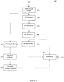
- Figure 3 shows schematically a simplified speech/audio encoder 104 according to some embodiments.
- FIG. 3 shows a simplified speech/audio encoder 300, an example of an encoder 104 according to some embodiments. Furthermore with respect to Figure 4 the operation of at least part of the speech/audio encoder 300 is shown in further detail.
- the simplified speech/audio encoder 300 as laid out in Figure 3 depicts a speech encoder conforming to the analysis-by-synthesis approach to speech coding, and that this coding approach only serves as an example into which the following line spectral frequencies determination method and apparatus can be deployed.
- the following method and apparatus for determining the line spectral frequencies can be equally deployed in any speech/audio encoder which uses LP coefficients or reflection coefficients to represent at least part of a speech/audio signal.
- the speech/audio encoder 300 is shown in Figure 3 as receiving the input speech/audio signal 110 via the audio sample framer 301.
- the audio sample framer 301 separates the input audio signal into frames of convenient length, typically of the order of tens of milliseconds.
- the audio sample framer 301 may segment the input speech/audio signal into frames of 20ms, which equates to a frame of length 160 samples when the input speech/audio signal has a digital sampling rate of 8kHz.
- the audio sample framer 301 can also be configured to perform a windowing operation over each frame, in order to smooth the speech/audio signal at the boundaries of each frame.
- Each frame may then be passed to an LPC analyser 303.
- the LPC analyser determines the LP coefficients for the frame. Typically the analysis of the input audio/speech frame is performed using the Levinson-Durbin algorithm in order to provide the LP coefficients.
- the output of the LPC analyser 303 in other words the LP coefficients may then be transformed into Line Spectral Frequencies (LSF) by the LSF determiner 305.
- LSFs are then typically quantised in preparation for transmission or storage by the LSF quantizer 307.
- the quantized LSFs may then be interpolated with quantized LSFs from a previously processed speech/audio frame.
- Each speech/audio frame may be partitioned into a number of subframes. For instance by way of an example a 20ms speech frame may be partitioned into 4 subframes each of duration 5ms.
- An LP analysis filter 311 can be constructed for each subframe by using a set of interpolated quantized LSFs from the LSF interpolator 309.
- the next stage in an analysis-by-synthesis coding structure typically involves the determination of the pitch lag and pitch gain from the long term predictor 313.
- a residual signal can then be generated by removing the long term predictor filter response from the speech/audio signal.
- the residual signal is then typically encoded using an excitation codebook 315.
- Quantized excitation codebook parameters along with quantized long term predictor parameters and quantized LSFs can be multiplexed by a multiplexer 317 into a bitstream 112 for transmission over a communication channel to a corresponding decoder 108.
- LSF determiner 305 as depicted in Figure 3 in which the LPC coefficients are transformed to their corresponding Line Spectral Frequency (LSFs) values.
- LSFs Line Spectral Frequency
- the LSFs may be derived by considering the nth degree predictor polynomial of the LP filter, n being the order of the LP filter.
- a n z 1 + a 1 z ⁇ 1 + ⁇ + a n z ⁇ n which satisfies the recurrence formula
- a n + 1 z A n z + k n + 1 z ⁇ n ⁇ 1 A n z ⁇ 1 wherein k 1 , k 2 , ..., k n +1 are reflection coefficients.
- the recurrence equation (2) is the Levsinson-Durbin solution to the Yule-Walker equations. It expresses the relationship between the (n+1)th and the nth degree predictor polynomials. For the purpose of this description it is assumed that all roots of the predictor polynomial A n ( z ) are inside the unit circle, in other words the predictor polynomial is of a minimum phase.
- equation (7) provide the odd numbered LSFs and equation (8) provides the even numbered LSFs. So from equation (7) it follows that the LSFs ⁇ 1 , ⁇ 3 , ..., ⁇ n-1 are the zeros of P(z) in the interval [0, ⁇ ], and from equation (8) it follows that the LSFs ⁇ 2 , ⁇ 4 , ..., ⁇ n are the zeros of Q(z) in the interval [0, ⁇ ]. It is to be further noted that the order of each of Q(z) and P(z) is half the order of the LP filter (or number of LP coefficients.)
- the invention proceeds on the basis of expressing the coefficients of each of the equations P(z) and Q(z) in terms of the signed sum and product of the roots of P(z) and Q(z) respectively, noting that P(z) and Q(z) are both equations in z and the roots of P(z) and Q(z) are the Line Spectral Pairs p k , and then to use signed sum and products of the roots S j k as the coefficients of a general form polynomial as given by equation (9).
- the general form polynomials associated with the coefficients of P(z) and Q(z) respectively can then be each solved using a low complexity technique to produce the Line Spectral Pairs p k .
- the general form polynomial associated with P(z) provides the odd ordered Line Spectral Pairs
- the general form polynomial associated with Q(z) provides the even ordered Line Spectral Pairs.
- n is the LP filter order.
- the odd indexed line spectral pairs p 1, p 3 ... p k -1 associated with P(z) will be considered in the following derivation.
- the following applies equally to the other polynomial Q(z) the roots of which give the even indexed LSPs.
- Each of the above expansions corresponds to a different LP filter order n.
- the method or apparatus configured to determine the line spectral pairs associated with a LP filter system herein has been laid out in terms of a specific example of an 8 th order LP filter system. It is to be further appreciated that the method or apparatus configured to determine herein described can be used to generate the line spectral pairs associated with other LP filter systems which have an even filter order. To that end there is shown below a Table 1 which lists the numerical weights c ij k associated with the coefficients t j k for LP filter systems with filter orders up to and including 10.
- Some implementations may store the numerical weights associated with the coefficients t j k for a particular LP filter order as a pre-calculated number rather than deriving them from the above recursive expression.
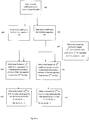
- FIG. 4 depicts the processing steps which can be executed as program codes on an apparatus 10 comprising a processor 21 for determining the line spectral pairs from the linear prediction coefficients in accordance with embodiments of the invention.
- the LPC analyser 303 can be configured to analyze the short term correlations in the frame of speech/audio samples in order to determine the LP coefficients. Typically in embodiments this may take the form of computing a matrix of correlation values and then finding a solution to a set of linear equations.
- the autocorrelation method may be used to derive the matrix of correlation values in which it is assumed that that the speech/audio samples lying outside the frame are zero.
- the autocorrelation matrix is of a Toeplitz form leading to the use of the Levinson-Durbin algorithm for solving the set of linear equations therefore yielding the LP coefficients.
- the covariance method may be used instead to derive the matrix of correlation values.
- the matrix of correlation values is found by finding the cross correlation between two very similar but not identical, finite-length samples sequences, in other words the matrix of correlation values is generated by using sample values which lie outside the analysis window.
- the correlation matrix is symmetrical about the leading diagonal, resulting in the use of efficient matrix inversion techniques such as Cholesky decomposition to solve the set of linear equations to find the LP coefficients.
- Further embodiments may use other techniques for finding the LP coefficients of a frame of speech/audio samples such as the technique of Lattice Methods.
- the step of determining the LP coefficients a j for a frame of Speech/audio samples is shown as processing step 401 in Figure 4 .
- the LP coefficients a j can be passed to the LSF determiner 305 for converting to their corresponding LSPs and ultimately to their corresponding LSFs.
- the LSF determiner 305 is configured to determine the coefficients for each of the polynomials Q(z) and P(z) by using the LP coefficients a j as determined by the previous processing stage 401.
- the coefficients for the symmetrical polynomial P(z) can be determined from the LP coefficients a j by using equation (3)
- the coefficients for the anti-symmetrical polynomial Q(z) can be determined from the LP coefficients a j by using equation (4).
- these processing steps may be realized in C code as
- the LSF determiner 305 can be configured to produce the numerical weights associated with the coefficients of t j k for use in the solving of the linear system of equations in terms of the product and sum of the line spectral pairs (11).
- the numerical weights c ij k is dependent on the filter order and can either be stored as pre-calculated numbers or calculated from equation (12).
- the processing step may be realized in C code as
- the number of equations comprising the coefficient linear system of equations is dependent on the LP filter order n. It is to be appreciated that that the numerical weights c ij k as produced by this processing step is applicable to both the polynomials P(z) and Q(z). In other words both polynomials use the same set of numerical weights c ij k in solving their respective coefficient linear system of equations. This is depicted in Figure 4 , where it can be seen that the output for processing step 407 is feed to both the subsequent coefficient linear system equation solving stages 409 and 411.
- the LSF determiner 305 is then configured to solve the linear system of coefficient equations t j k (11) in order to determine the product product and sum of the line spectral frequencies S j k .
- this can be performed in a recursive manner starting with t 1 k which would yield the value for S 1 k , and then solve the linear equation for t 2 k which would yield the value for S 2 k , the value for S 1 k can then be used to solve the linear equation for t 3 k to yield S 3 k and so on.
- the process is performed separately for both the coefficients of P(z) and the coefficients of Q(z).
- the C source code performing these processing steps may be given as
- the LSF determiner 305 can then be configured to solve a general polynomial of the form shown by equation (9) which is associated with the polynomial P(z) whose coefficients are the sum of the products S j k as determined by the processing step 409 .
- the LSF determiner 305 is also configured to solve the general polynomial associated with the polynomial Q(z) whose coefficients are the sum of the products S j k as determined by the processing step 411.
- the roots of the respective general polynomial are the line spectral pairs associated with the polynomials P(z) and Q(z) respectively.
- the general polynomial associated with each of the polynomial P(z) and Q(z) can be solved using the computationally efficient Horner's method.
- embodiments of the application operating within a codec within an apparatus 10
- the invention as described above may be implemented as part of any audio (or speech) codec.
- embodiments of the application may be implemented in an audio codec which may implement audio coding over fixed or wired communication paths, or for store and forward applications such as a music player.
- the LP filter order together with the LSF and LSP orders used above are exemplary, and the codec may be configured to implement LP filter systems at other LP filter orders.
- user equipment may comprise an audio codec such as those described in embodiments of the application above.
- user equipment is intended to cover any suitable type of wireless user equipment, such as mobile telephones, portable data processing devices or portable web browsers.
- elements of a public land mobile network may also comprise elements of a stereoscopic video capture and recording device as described above.
- the various embodiments of the application may be implemented in hardware or special purpose circuits, software, logic or any combination thereof.
- some aspects may be implemented in hardware, while other aspects may be implemented in firmware or software which may be executed by a controller, microprocessor or other computing device, although the invention is not limited thereto.
- firmware or software which may be executed by a controller, microprocessor or other computing device, although the invention is not limited thereto.
- While various aspects of the application may be illustrated and described as block diagrams, flow charts, or using some other pictorial representation, it is well understood that these blocks, apparatus, systems, techniques or methods described herein may be implemented in, as non-limiting examples, hardware, software, firmware, special purpose circuits or logic, general purpose hardware or controller or other computing devices, or some combination thereof.
- any blocks of the logic flow as in the Figures may represent program steps, or interconnected logic circuits, blocks and functions, or a combination of program steps and logic circuits, blocks and functions.
- the memory may be of any type suitable to the local technical environment and may be implemented using any suitable data storage technology, such as semiconductor-based memory devices, magnetic memory devices and systems, optical memory devices and systems, fixed memory and removable memory.
- the data processors may be of any type suitable to the local technical environment, and may include one or more of general purpose computers, special purpose computers, microprocessors, digital signal processors (DSPs), application specific integrated circuits (ASIC), gate level circuits and processors based on multi-core processor architecture, as non-limiting examples.
- Embodiments of the application may be practiced in various components such as integrated circuit modules.
- the design of integrated circuits is by and large a highly automated process. Complex and powerful software tools are available for converting a logic level design into a semiconductor circuit design ready to be etched and formed on a semiconductor substrate.
- Programs can automatically route conductors and locate components on a semiconductor chip using well established rules of design as well as libraries of pre-stored design modules.
- the resultant design in a standardized electronic format (e.g., Opus, GDSII, or the like) may be transmitted to a semiconductor fabrication facility or "fab" for fabrication.
- circuitry refers to all of the following:
- circuitry' applies to all uses of this term in this application, including any claims.
- the term 'circuitry' would also cover an implementation of merely a processor (or multiple processors) or portion of a processor and its (or their) accompanying software and/or firmware.
- the term 'circuitry' would also cover, for example and if applicable to the particular claim element, a baseband integrated circuit or applications processor integrated circuit for a mobile phone or similar integrated circuit in server, a cellular network device, or other network device.
Landscapes
- Engineering & Computer Science (AREA)
- Physics & Mathematics (AREA)
- Computational Linguistics (AREA)
- Signal Processing (AREA)
- Health & Medical Sciences (AREA)
- Audiology, Speech & Language Pathology (AREA)
- Human Computer Interaction (AREA)
- Acoustics & Sound (AREA)
- Multimedia (AREA)
- Spectroscopy & Molecular Physics (AREA)
- Compression, Expansion, Code Conversion, And Decoders (AREA)
Abstract
Description
- The present invention relates to speech encoding methods, and in particular, to linear predictive coding (LPC) speech and audio coding techniques that employ line spectral frequency representation of a LPC filter.
- Linear predictive coding (LPC) is a technique used extensively in speech and audio coding for analysing the short term correlations in signal. The short term correlations of the speech/audio signal are modelled using a Linear Prediction (LP) filter whose coefficients are derived directly by using linear prediction analysis over the incoming signal. However, in order that the LP coefficients can be encoded for transmission or storage, they are typically transformed into another mathematical format in order to place them in a form that makes them more suitable for the subsequent steps of quantization and interpolation. One such form which has been found to be more amenable than most for quantization and interpolation is the transformation of the LP coefficients into Line Spectral Frequencies (LSF). A known property of LSF parameters is that they normally present themselves in an ascending order. This ascending ordering is an important aspect of speech coding because it guarantees the stability of the LP filter, which is vital to ensuring good sound quality.
- However, in known types of speech encoders that employ LSFs to represent the LP coefficients, the procedure for deriving the LSFs is computationally expensive.
- Aspects of this application thus provide an efficient method and apparatus for determining line spectral pairs.
- There is provided according to the application a method for determining line spectral pairs for a linear prediction filter whose filter coefficients are linear predictive coefficients determined over a frame of audio samples, wherein the linear prediction filter is expressed as symmetric and antisymmetric polynomials, the zeros of which determine the line spectral pairs of the LP filter, comprising for each symmetric and antisymmetric polynomial: expanding the polynomial into an expanded polynomial; arranging each coefficient of a plurality of coefficients of the expanded polynomial into at least one sum of terms of the same product order; arranging the plurality of coefficients of the expanded polynomial into a linear system of equations and solving the linear system of equations to give a value for the at least one sum of terms of the same product order for each of the plurality of coefficients; forming a further polynomial, wherein a coefficient of the further polynomial is a value for at least one sum of terms of the same product order for a coefficient of the expanded polynomial; and solving the further polynomial wherein the roots of the further polynomial are line spectral pairs.
- Arranging the coefficients into a linear system of equations may further comprise equating the at least one sum of terms of the same product order to a coefficient of the polynomial.
- Solving the linear system of equations to give a value for the at least one sum of terms of the same product order may be solved in a recursive manner.
- Solving the further polynomial may comprise using Horner's method.
- The at least one sum of terms of the same product may be a sum of line spectral pairs of the same product order.
- The further polynomial can be a general polynomial of the form


- The at least one sum of line spectral pairs of product order three,


- According to a second aspect there is an apparatus configured to determine line spectral pairs for a linear prediction filter whose filter coefficients are linear predictive coefficients determined over a frame of audio samples, wherein the linear prediction filter is expressed as symmetric and antisymmetric polynomials, the zeros of which determine the line spectral pairs of the LP filter, wherein the apparatus is configured to for each symmetric and antisymmetric polynomial: expand the polynomial into an expanded polynomial; arrange each coefficient of a plurality of coefficients of the expanded polynomial into at least one sum of terms of the same product order; arrange the plurality of coefficients of the expanded polynomial into a linear system of equations and solving the linear system of equations to give a value for the at least one sum of terms of the same product order for each of the plurality of coefficients; form a further polynomial, wherein a coefficient of the further polynomial is a value for at least one sum of terms of the same product order for a coefficient of the expanded polynomial; and
solve the further polynomial wherein the roots of the further polynomial are line spectral pairs. - The apparatus configured to arrange the coefficients into a linear system of equations may be further configured to equate the at least one sum of terms of the same product order to a coefficient of the polynomial.
- The apparatus configured to solve the linear system of equations to give a value for the at least one sum of terms of the same product order may be configured to solve the linear system of equations in a recursive manner.
- The apparatus configured to solve the further polynomial can be configured to use Horner's method.
- The at least one sum of terms of the same product order may be a sum of line spectral pairs of the same product order.
- Tthe further polynomial may be a general polynomial of the form


- The at least one sum of line spectral pairs of product order three,


- According to another aspect there is provided an apparatus comprising at least one processor and at least one memory including computer program code, the at least one memory and the computer program code configured to, with the at least one processor, cause the apparatus to determine line spectral pairs for a linear prediction filter whose filter coefficients are linear predictive coefficients determined over a frame of audio samples, wherein the linear prediction filter is expressed as symmetric and antisymmetric polynomials, the zeros of which determine the line spectral pairs of the LP filter, wherein the apparatus is caused to for each symmetric and antisymmetric polynomial: expand the polynomial into an expanded polynomial; arrange each coefficient of a plurality of coefficients of the expanded polynomial into at least one sum of terms of the same product order; arrange the plurality of coefficients of the expanded polynomial into a linear system of equations and solving the linear system of equations to give a value for the at least one sum of terms of the same product order for each of the plurality of coefficients; form a further polynomial, wherein a coefficient of the further polynomial is a value for at least one sum of terms of the same product order for a coefficient of the expanded polynomial; and solve the further polynomial wherein the roots of the further polynomial are line spectral pairs. The apparatus configured to arrange the coefficients into a linear system of equations may be further configured to equate the at least one sum of terms of the same product order to a coefficient of the polynomial.
- The apparatus caused to solve the linear system of equations to give a value for the at least one sum of terms of the same product order may be caused to solve the linear system of equations in a recursive manner.
- The apparatus caused to solve the further polynomial can be caused to use Horner's method.
- The at least one sum of terms of the same product order may be a sum of line spectral pairs of the same product order.
- Tthe further polynomial may be a general polynomial of the form


- The at least one sum of line spectral pairs of product order three,



- According to another aspect there is provided a computer-readable medium having computer-readable code stored thereon, the computer readable code, when executed by a least one processor, causing an apparatus to: determine line spectral pairs for a linear prediction filter whose filter coefficients are linear predictive coefficients determined over a frame of audio samples, wherein the linear prediction filter is expressed as symmetric and antisymmetric polynomials, the zeros of which determine the line spectral pairs of the LP filter, wherein the apparatus is caused to for each symmetric and antisymmetric polynomial: expand the polynomial into an expanded polynomial; arrange each coefficient of a plurality of coefficients of the expanded polynomial into at least one sum of terms of the same product order; arrange the plurality of coefficients of the expanded polynomial into a linear system of equations and solving the linear system of equations to give a value for the at least one sum of terms of the same product order for each of the plurality of coefficients; form a further polynomial, wherein a coefficient of the further polynomial is a value for at least one sum of terms of the same product order for a coefficient of the expanded polynomial; and solve the further polynomial wherein the roots of the further polynomial are line spectral pairs. The apparatus configured to arrange the coefficients into a linear system of equations may be further configured to equate the at least one sum of terms of the same product order to a coefficient of the polynomial.
- The computer-readable medium having computer-readable code stored thereon, which causes the apparatus to solve the linear system of equations to give a value for the at least one sum of terms of the same product order may cause the apparatus to solve the linear system of equations in a recursive manner.
- The computer-readable medium having computer-readable code stored thereon, which causes the apparatus to solve the further polynomial can cause to the apparatus to use Horner's method.
- The at least one sum of terms of the same product order may be a sum of line spectral pairs of the same product order.
- The further polynomial may be a general polynomial of the form


- The at least one sum of line spectral pairs of product order three,




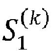

- According to another aspect of there is provided a computer program code for determining line spectral pairs for a linear prediction filter whose filter coefficients are linear predictive coefficients determined over a frame of audio samples, wherein the linear prediction filter is expressed as symmetric and antisymmetric polynomials, the zeros of which determine the line spectral pairs of the LP filter, realizing the following when executed by a processor: expanding the polynomial into an expanded polynomial; arranging each coefficient of a plurality of coefficients of the expanded polynomial into at least one sum of terms of the same product order; arranging the plurality of coefficients of the expanded polynomial into a linear system of equations and solving the linear system of equations to give a value for the at least one sum of terms of the same product order for each of the plurality of coefficients; forming a further polynomial, wherein a coefficient of the further polynomial is a value for at least one sum of terms of the same product order for a coefficient of the expanded polynomial; and solving the further polynomial wherein the roots of the further polynomial are line spectral pairs.
- For better understanding of the present application and as to how the same may be carried into effect, reference will now be made by way of example to the accompanying drawings in which:
-
Figure 1 shows schematically an electronic device employing some embodiments; -
Figure 2 shows schematically an audio codec system according to some embodiments; -
Figure 3 shows schematically a simplified encoder as shown inFigure 2 according to some embodiments; and -
Figure 4 shows a flow diagram illustrating the process of determining line spectral pairs according to embodiments. - The invention proceeds from the consideration that the procedure for calculating the line spectral frequencies in existing speech and audio codecs can be computationally expensive, and that there is a need to reduce this burden.
- In this regard reference is first made to
Figure 1 which shows a schematic block diagram of an exemplary electronic device orapparatus 10, which may incorporate a codec according to an embodiment of the application. - The
apparatus 10 may for example be a mobile terminal or user equipment of a wireless communication system. In other embodiments theapparatus 10 may be an audio-video device such as video camera, a Television (TV) receiver, audio recorder or audio player such as a mp3 recorder/player, a media recorder (also known as a mp4 recorder/player), or any computer suitable for the processing of audio signals. - The electronic device or
apparatus 10 in some embodiments comprises amicrophone 11, which is linked via an analogue-to-digital converter (ADC) 14 to aprocessor 21. Theprocessor 21 is further linked via a digital-to-analogue (DAC)converter 32 toloudspeakers 33. Theprocessor 21 is further linked to a transceiver (RX/TX) 13, to a user interface (UI) 15 and to amemory 22. - The
processor 21 can in some embodiments be configured to execute various program codes. The implemented program codes in some embodiments comprise a multichannel or stereo encoding or decoding code as described herein. The implementedprogram codes 23 can in some embodiments be stored for example in thememory 22 for retrieval by theprocessor 21 whenever needed. Thememory 22 could further provide asection 24 for storing data, for example data that has been encoded in accordance with the application. - The encoding and decoding code in embodiments can be implemented in hardware and/or firmware.
- The
user interface 15 enables a user to input commands to theelectronic device 10, for example via a keypad, and/or to obtain information from theelectronic device 10, for example via a display. In some embodiments a touch screen may provide both input and output functions for the user interface. Theapparatus 10 in some embodiments comprises atransceiver 13 suitable for enabling communication with other apparatus, for example via a wireless communication network. - It is to be understood again that the structure of the
apparatus 10 could be supplemented and varied in many ways. - A user of the
apparatus 10 for example can use themicrophone 11 for inputting speech or other audio signals that are to be transmitted to some other apparatus or that are to be stored in thedata section 24 of thememory 22. A corresponding application in some embodiments can be activated to this end by the user via theuser interface 15. This application in these embodiments can be performed by theprocessor 21, causes theprocessor 21 to execute the encoding code stored in thememory 22. - The analogue-to-digital converter (ADC) 14 in some embodiments converts the input analogue audio signal into a digital audio signal and provides the digital audio signal to the
processor 21. In some embodiments themicrophone 11 can comprise an integrated microphone and ADC function and provide digital audio signals directly to the processor for processing. - The
processor 21 in such embodiments then processes the digital audio signal in the same way as described with reference to the system shown inFigure 2 and the encoder shown inFigures 3 . - The resulting bit stream can in some embodiments be provided to the
transceiver 13 for transmission to another apparatus. Alternatively, the coded audio data in some embodiments can be stored in thedata section 24 of thememory 22, for instance for a later transmission or for a later presentation by thesame apparatus 10. - The
apparatus 10 in some embodiments can also receive a bit stream with correspondingly encoded data from another apparatus via thetransceiver 13. In this example, theprocessor 21 may execute the decoding program code stored in thememory 22. Theprocessor 21 in such embodiments decodes the received data, and provides the decoded data to a digital-to-analogue converter 32. The digital-to-analogue converter 32 converts the digital decoded data into analogue audio data and can in some embodiments output the analogue audio via theloudspeakers 33. Execution of the decoding program code in some embodiments can be triggered as well by an application called by the user via theuser interface 15. - The received encoded data in some embodiment can also be stored instead of an immediate presentation via the
loudspeakers 33 in thedata section 24 of thememory 22, for instance for later decoding and presentation or decoding and forwarding to still another apparatus. - It would be appreciated that the schematic structures described in
Figures 1 to 3 , and the method steps shown inFigure 4 represent only a part of the operation of an audio codec or speech codec and specifically part of apparatus or method for determining Line Spectral Frequencies as exemplarily shown implemented in the apparatus shown inFigure 1 . - The general operation of audio or speech codecs as employed by embodiments is shown in
Figure 2 . In general speech and audio coding/decoding systems can comprise both an encoder and a decoder, as illustrated schematically inFigure 2 . However, it would be understood that some embodiments can implement one of either the encoder or decoder, or both the encoder and decoder. Illustrated byFigure 2 is asystem 102 with anencoder 104 and in particular a speech/audio signal encoder, a storage ormedia channel 106 and adecoder 108. It would be understood that as described above some embodiments can comprise or implement one of theencoder 104 ordecoder 108 or both theencoder 104 anddecoder 108. - The
encoder 104 compresses an input audio/speech signal 110 producing abit stream 112, which in some embodiments can be stored or transmitted through amedia channel 106. Theencoder 104 furthermore can comprise a speech/audio encoder 151 as part of the overall encoding operation. It is to be understood that the speech/audio encoder may be part of theoverall encoder 104 or a separate encoding module. - The
bit stream 112 can be received within thedecoder 108. Thedecoder 108 decompresses thebit stream 112 and produces an output audio/speech signal 114. Thedecoder 108 can comprise an audio/speech decoder as part of the overall decoding operation. It is to be understood that the audio/speech decoder may be part of theoverall decoder 108 or a separate decoding module. The bit rate of thebit stream 112 and the quality of theoutput audio signal 114 in relation to theinput signal 110 are the main features which define the performance of thecoding system 102. -
Figure 3 shows schematically a simplified speech/audio encoder 104 according to some embodiments. - The concept for the embodiments as described herein is to determine the LPC coefficients for an input audio/speech frame, and from the LP coefficients determine the corresponding line spectral frequencies. In that regard
Figure 3 shows a simplified speech/audio encoder 300, an example of anencoder 104 according to some embodiments. Furthermore with respect toFigure 4 the operation of at least part of the speech/audio encoder 300 is shown in further detail. - It is to be appreciated that the simplified speech/
audio encoder 300 as laid out inFigure 3 depicts a speech encoder conforming to the analysis-by-synthesis approach to speech coding, and that this coding approach only serves as an example into which the following line spectral frequencies determination method and apparatus can be deployed. - It is therefore to be further appreciated that the following method and apparatus for determining the line spectral frequencies can be equally deployed in any speech/audio encoder which uses LP coefficients or reflection coefficients to represent at least part of a speech/audio signal.
- The speech/
audio encoder 300 is shown inFigure 3 as receiving the input speech/audio signal 110 via theaudio sample framer 301. Theaudio sample framer 301 separates the input audio signal into frames of convenient length, typically of the order of tens of milliseconds. For example in an embodiment theaudio sample framer 301 may segment the input speech/audio signal into frames of 20ms, which equates to a frame of length 160 samples when the input speech/audio signal has a digital sampling rate of 8kHz. In addition theaudio sample framer 301 can also be configured to perform a windowing operation over each frame, in order to smooth the speech/audio signal at the boundaries of each frame. - Each frame may then be passed to an
LPC analyser 303. The LPC analyser determines the LP coefficients for the frame. Typically the analysis of the input audio/speech frame is performed using the Levinson-Durbin algorithm in order to provide the LP coefficients. The output of theLPC analyser 303, in other words the LP coefficients may then be transformed into Line Spectral Frequencies (LSF) by theLSF determiner 305. The LSFs are then typically quantised in preparation for transmission or storage by theLSF quantizer 307. The quantized LSFs may then be interpolated with quantized LSFs from a previously processed speech/audio frame. Interpolation of the quantized LSFs is depicted inFigure 3 as being performed by the LSF interpolator 309 inFigure 3 . Each speech/audio frame may be partitioned into a number of subframes. For instance by way of an example a 20ms speech frame may be partitioned into 4 subframes each of duration 5ms. AnLP analysis filter 311 can be constructed for each subframe by using a set of interpolated quantized LSFs from theLSF interpolator 309. The next stage in an analysis-by-synthesis coding structure typically involves the determination of the pitch lag and pitch gain from thelong term predictor 313. A residual signal can then be generated by removing the long term predictor filter response from the speech/audio signal. The residual signal is then typically encoded using anexcitation codebook 315. Quantized excitation codebook parameters along with quantized long term predictor parameters and quantized LSFs can be multiplexed by amultiplexer 317 into abitstream 112 for transmission over a communication channel to acorresponding decoder 108. - The following description pertains most particularly to the operation of the
LSF determiner 305 as depicted inFigure 3 in which the LPC coefficients are transformed to their corresponding Line Spectral Frequency (LSFs) values. To that end the LSFs may be derived by considering the nth degree predictor polynomial of the LP filter, n being the order of the LP filter.

- By setting k n+1 = 1, the recurrence equation (2) gives the polynomial


- Similarly, by setting k n+1 = -1 in (3) the antisymmetric polynomial Q(z) is obtained:

- From (3) and (4) it follows that An (z) can be decomposed in a sum of symmetric and antisymmetric polynomials:
- It is to be appreciated that the roots of the polynomials P n+1(z) and Q n+1(z) provide the Line Spectral Pairs (LSP) of the predictor polynomial. In the IEEE publication by Soong and Juang entitled "Line Spectrum Pair (LSP) and speech data compression", in the proceedings of IEEE International Conference on Acoustics, Speech and Signal Processing, San Diego, CA, pp1.10.1 to 1.10.4, March 1984, which is incorporated herein by reference, it has been shown that if An (z) is minimum phase, then the LSFs are on the unit circle, and the roots are simple and separate from each other. This follows therefore that P n+1(z) and Q n+1(z) can be factored as follows:
- Traditionally equations (7) and (8) are solved to give the Line Spectral Pairs (LSP) p,p2 ,..., pn which are defined as the cosine of the LSF, cosωn.
- Furthermore it is to be noted that equation (7) provide the odd numbered LSFs and equation (8) provides the even numbered LSFs. So from equation (7) it follows that the LSFs ω 1, ω 3, ..., ω n-1 are the zeros of P(z) in the interval [0,π], and from equation (8) it follows that the LSFs ω 2, ω 4, ..., ωn are the zeros of Q(z) in the interval [0, π]. It is to be further noted that the order of each of Q(z) and P(z) is half the order of the LP filter (or number of LP coefficients.)
- Traditionally the method of Chebyshev polynomials is used to find the roots of equations (7) and (8) in order to obtain the LSFs ω 1, ω 3, ..., ω n-1 and LSFs ω 2, ω 4, ..., ωn respectively (or LSPs p,p 3, ... , p n-1 and LSPs p 2, p 4, ... , pn respectively)
- This method is based on exploiting the symmetry of equations (7) and (8) and making the substitution of zk + z-k = ejωk + e-jωk = 2cosωk resulting in (7) and (8) each being a cosine based series. In order to obviate the evaluation of the trigonometric functions, Kabel and Ranachandran suggested in "The computation of line spectrum frequencies using Chebyshev polynomials" IEEE Transactions on Acoustics, Speech and Signal Processing vol.34, no. 6, pp.1419-1426, 1986, that Chebyshev polynomials could be used to transform the cosine based series, and then employ a bisection algorithm to find the roots.
- The approach by Kabel and Ramachandran has been shown to be numerically robust, however it requires a significant number of additions and multiplications to implement.
- In accordance with the teaching of embodiments, a reduction in the complexity of the computation of line spectral frequencies is made possible by evaluating both Q(z) and P(z) as a general polynomial of the form


- In accordance, the invention proceeds on the basis of expressing the coefficients of each of the equations P(z) and Q(z) in terms of the signed sum and product of the roots of P(z) and Q(z) respectively, noting that P(z) and Q(z) are both equations in z and the roots of P(z) and Q(z) are the Line Spectral Pairs pk , and then to use signed sum and products of the roots

- The methods of this invention are presented in more detail by the following description in conjunction with
Figure 3 . - The coefficients of each of P(z) and Q(z) can be expressed in terms of the signed sum and products of the roots by considering each of P(z) and Q(z) as a product of k = n/2 factors, where n is the LP filter order. In order to simplify the notation only the odd indexed line spectral pairs p 1, p 3 ... p k-1 associated with P(z) will be considered in the following derivation. However, it is to be understood that the following applies equally to the other polynomial Q(z) the roots of which give the even indexed LSPs.
- Considering the line spectral frequencies ω 1, ω 2, ..., ωn of An (z), such that 0 < ω 1 < ω 2 < ···, < ωn < π, then the line spectral pairs can be expressed as


- Expanding equation (10) as the product of k factors such that P(z) = P (k)(z) produces the following series for the first four expansions

- Each of the above expansions corresponds to a different LP filter order n.
- The coefficients of P (k)(z) can be denoted by





- In this instance the above system for k =4 corresponds to a LP filter system An (z) of order 8 (n = 8), and the above system for k=3 corresponds to a LP filter system An (z) of order 6 (n = 6), and so on.
- From above it can be seen that the coefficients of the polynomial P(z) can be written as a linear system of equations comprising the product and sum of the line spectral pairs with associated numerical weights.
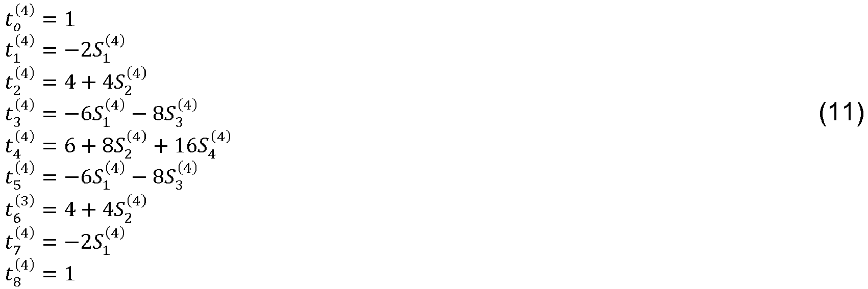
- Where the following product and sums of the line spectral pairs in this instance are


- It is to be appreciated that the coefficients of the polynomial for P(z),


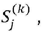
- As described above once the signed sums and products of the line spectral pairs

- For instance, for the above case in which the LP filter system comprises 8 LPC coefficients the general polynomial will be of the form

- In embodiments the above general form polynomial can solved by the efficient procedure of nested multiplications, known as Horner's method (see, for example, Kincaid and Cheney, Numerical Analysis: Mathematics of Scientific Computing, Brooks/Cole Publishing Company, 1991).
- By using the Horner's method for solving the above general form polynomial, results in a significant reduction in instruction cycles when compared to the traditional method of using Chebyshev polynomials as mentioned above. For example the traditional method of using Chebyshev polynomials for solving either of Q(z) or P(z) consumes approximately (NC+1) multiplications and (2NC-1) additions, whereas comparatively the above method using Horner's method consumes approximately NC multiplications and NC additions. These savings in instruction cycles can achieve a significant reduction in complexity when determining the LSFs as both methods find the roots of a respective polynomial by evaluating the polynomial hundreds of times per frame.
- It is to be appreciated that the method or apparatus configured to determine the line spectral pairs associated with a LP filter system herein has been laid out in terms of a specific example of an 8th order LP filter system. It is to be further appreciated that the method or apparatus configured to determine herein described can be used to generate the line spectral pairs associated with other LP filter systems which have an even filter order. To that end there is shown below a Table 1 which lists the numerical weights


k=2 k=3 k=4 k=5 S 0 S 1 S 2 S 0 S 1 S 2 S 3 S 0 S 1 S 2 S 3 S 4 S 0 S 1 S 2 S 3 S 4 S 5 
1 1 1 1 
0 -2 0 -2 0 -2 0 -2 
2 0 4 3 0 4 4 0 4 5 0 4 
0 -2 0 -4 0 -8 0 -6 0 -8 0 -8 0 -8 
1 3 0 4 6 0 8 0 16 10 0 12 0 16 
0-2 0 -6 0 -8 0 -12 0 -16 0 -32 
1 4 0 4 10 0 12 0 16 
0 -2 0 -8 0 -8 
1 5 0 4 
0 -2 
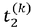
1 - On a general basis the numerical weights associated with the coefficients

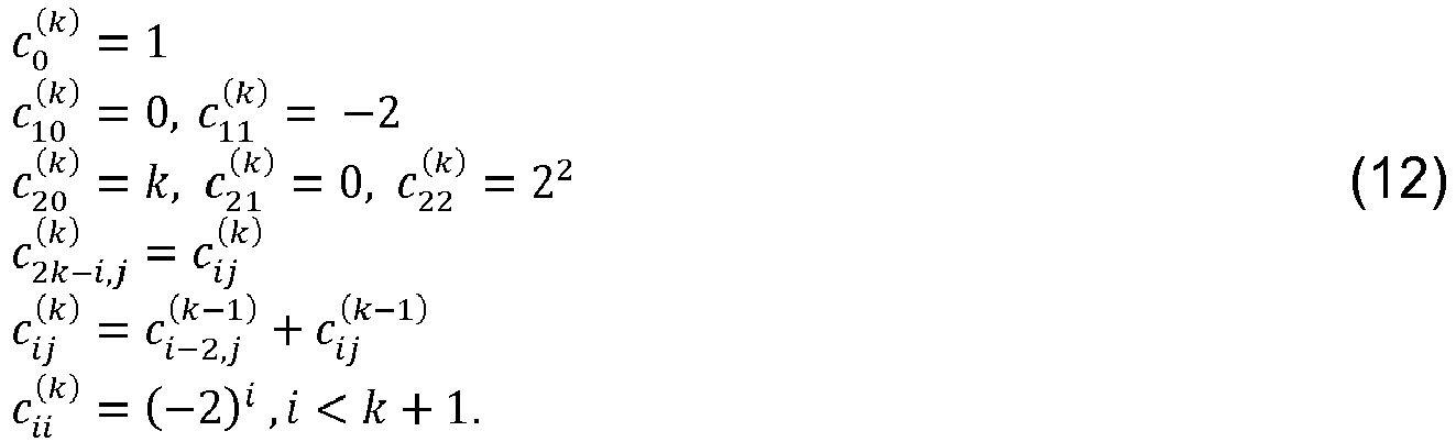
- Therefore based on the above nomenclature the coefficients
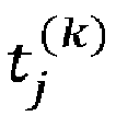


- Some implementations may store the numerical weights associated with the coefficients

- The following
Figure 4 depicts the processing steps which can be executed as program codes on anapparatus 10 comprising aprocessor 21 for determining the line spectral pairs from the linear prediction coefficients in accordance with embodiments of the invention. - In this respect the
LPC analyser 303 can be configured to analyze the short term correlations in the frame of speech/audio samples in order to determine the LP coefficients. Typically in embodiments this may take the form of computing a matrix of correlation values and then finding a solution to a set of linear equations. In one embodiment the autocorrelation method may be used to derive the matrix of correlation values in which it is assumed that that the speech/audio samples lying outside the frame are zero. In this particular embodiment the autocorrelation matrix is of a Toeplitz form leading to the use of the Levinson-Durbin algorithm for solving the set of linear equations therefore yielding the LP coefficients. - In another embodiment the covariance method may be used instead to derive the matrix of correlation values. In this case the matrix of correlation values is found by finding the cross correlation between two very similar but not identical, finite-length samples sequences, in other words the matrix of correlation values is generated by using sample values which lie outside the analysis window. In this embodiment the correlation matrix is symmetrical about the leading diagonal, resulting in the use of efficient matrix inversion techniques such as Cholesky decomposition to solve the set of linear equations to find the LP coefficients.
- Further embodiments may use other techniques for finding the LP coefficients of a frame of speech/audio samples such as the technique of Lattice Methods.
- The step of determining the LP coefficients aj for a frame of Speech/audio samples is shown as processing
step 401 inFigure 4 . - In embodiments the LP coefficients aj can be passed to the
LSF determiner 305 for converting to their corresponding LSPs and ultimately to their corresponding LSFs. - The
LSF determiner 305 is configured to determine the coefficients for each of the polynomials Q(z) and P(z) by using the LP coefficients aj as determined by theprevious processing stage 401. The coefficients for the symmetrical polynomial P(z) can be determined from the LP coefficients aj by using equation (3), and the coefficients for the anti-symmetrical polynomial Q(z) can be determined from the LP coefficients aj by using equation (4). For example, these processing steps may be realized in C code as
- The steps of determining the coefficients for the polynomials P(z) and Q(z) is shown as processing
steps Figure 4 . - The
LSF determiner 305 can be configured to produce the numerical weights associated with the coefficients of


               build_sums_coeffs(intl6_t m)
               {
                  int16_t i, n;
                  for (i = 0; i < 2 * m + 1; i++)
                 {
                    vec_set_d(sums_coeffs[i], 0.0f, m + 1);
                  }
                   sums_coeffs[0][0] = 1;
                   sums_coeffs[1][1] = -2;
                   sums_coeffs[2][0] = 2;
                   sums_coeffs[2][2] = 4;
                   n = 3;
                   while (n <= m)
                   {
                      vec_d_mul_s(sums_coeffs[n - 2], 2.0f, sums_coeffs[n], n);
                      sums_coeffs[n][n] = -2 * sums_coeffs[n - 1][n - 1];
                      for (i = n - 1; i >= 2; i--)
                      {
            vec_d_add_v(sums_coeffs[i - 2], sums_coeffs[i], sums_coeffs[i], n);
                      }
                      n++;
                  }
                  return;
               }




 sp[0] = 1;
 for (i = 1; i <= nc; i++)
 {
      sp[i] = (float32_t)((pz[i] - vec_dot_df(sums_coeffs[i], sp, i)) /
 (double)(sums_coeffs[i][i]));
 }
 sq[0] = 1;
 for (i = 1; i <= nc; i++)
 {
     sq[i] = (float32_t)((qz[i] - vec_dot_df(sums_coeffs[i], sq, i)) /
 (double)(sums_coeffs[i][i]));
 }
 ip = -1;
 for (i = 1; i <= nc; i++)
 {
      sp[i] = ip*sp[i];
      sq[i] = ip*sq[i];
      ip *= -1;
 }


- (a) hardware-only circuit implementations (such as implementations in only analog and/or digital circuitry) and
- (b) to combinations of circuits and software (and/or firmware), such as: (i) to a combination of processor(s) or (ii) to portions of processor(s)/software (including digital signal processor(s)), software, and memory(ies) that work together to cause an apparatus, such as a mobile phone or server, to perform various functions and
- (c) to circuits, such as a microprocessor(s) or a portion of a microprocessor(s), that require software or firmware for operation, even if the software or firmware is not physically present.
Claims (15)
- A method for determining line spectral pairs for a linear prediction filter whose filter coefficients are linear predictive coefficients determined over a frame of audio samples, wherein the linear prediction filter is expressed as symmetric and antisymmetric polynomials, the zeros of which determine the line spectral pairs of the LP filter, comprising for each symmetric and antisymmetric polynomial:expanding the polynomial into an expanded polynomial;arranging each coefficient of a plurality of coefficients of the expanded polynomial into at least one sum of terms of the same product order;arranging the plurality of coefficients of the expanded polynomial into a linear system of equations and solving the linear system of equations to give a value for the at least one sum of terms of the same product order for each of the plurality of coefficients;forming a further polynomial, wherein a coefficient of the further polynomial is a value for at least one sum of terms of the same product order for a coefficient of the expanded polynomial; andsolving the further polynomial wherein the roots of the further polynomial are line spectral pairs.
- The method according to Claim 1, wherein arranging the coefficients into a linear system of equations further comprises:equating the at least one sum of terms of the same product order to a coefficient of the polynomial.
- The method according to Claims 1 and 2, wherein solving the linear system of equations to give a value for the at least one sum of terms of the same product order is solved in a recursive manner.
- The method according to Claims 1 to 3, wherein solving the further polynomial comprises using Horner's method.
- The method according to Claims 1 to 4, wherein the at least one sum of terms of the same product order are a sum of line spectral pairs of the same product order.
- The method according to Claim 5, wherein the further polynomial is a general polynomial of the form


- The method according to Claim 6, wherein the at least one sum of line spectral pairs of product order three,


- An apparatus configured to determine line spectral pairs for a linear prediction filter whose filter coefficients are linear predictive coefficients determined over a frame of audio samples, wherein the linear prediction filter is expressed as symmetric and antisymmetric polynomials, the zeros of which determine the line spectral pairs of the LP filter, wherein the apparatus is configured to for each symmetric and antisymmetric polynomial:expand the polynomial into an expanded polynomial;arrange each coefficient of a plurality of coefficients of the expanded polynomial into at least one sum of terms of the same product order;arrange the plurality of coefficients of the expanded polynomial into a linear system of equations and solving the linear system of equations to give a value for the at least one sum of terms of the same product order for each of the plurality of coefficients;form a further polynomial, wherein a coefficient of the further polynomial is a value for at least one sum of terms of the same product order for a coefficient of the expanded polynomial; andsolve the further polynomial wherein the roots of the further polynomial are line spectral pairs.
- The apparatus according to Claim 8, wherein the apparatus configured to arrange the coefficients into a linear system of equations is further configured to:equate the at least one sum of terms of the same product order to a coefficient of the polynomial.
- The apparatus according to Claims 8 and 9, wherein the apparatus configured to solve the linear system of equations to give a value for the at least one sum of terms of the same product order is configured to solve the linear system of equations in a recursive manner.
- The apparatus according to Claims 8 to 10, wherein the apparatus configured to solve the further polynomial is configured to use Horner's method.
- The apparatus according to Claims 8 to 11, wherein the at least one sum of terms of the same product order are a sum of line spectral pairs of the same product order.
- The apparatus according to Claim 12, wherein the further polynomial is a general polynomial of the form


- The apparatus according to Claim 13, wherein the at least one sum of line spectral pairs of product order three,


- A computer program code for determining line spectral pairs for a linear prediction filter whose filter coefficients are linear predictive coefficients determined over a frame of audio samples, wherein the linear prediction filter is expressed as symmetric and antisymmetric polynomials, the zeros of which determine the line spectral pairs of the LP filter, realizing the following when executed by a processor:expanding the polynomial into an expanded polynomial;arranging each coefficient of a plurality of coefficients of the expanded polynomial into at least one sum of terms of the same product order;arranging the plurality of coefficients of the expanded polynomial into a linear system of equations and solving the linear system of equations to give a value for the at least one sum of terms of the same product order for each of the plurality of coefficients;forming a further polynomial, wherein a coefficient of the further polynomial is a value for at least one sum of terms of the same product order for a coefficient of the expanded polynomial; andsolving the further polynomial wherein the roots of the further polynomial are line spectral pairs.
Priority Applications (2)
| Application Number | Priority Date | Filing Date | Title |
|---|---|---|---|
| EP17151305.4A EP3349212A1 (en) | 2017-01-13 | 2017-01-13 | Method for determining line spectral frequencies |
| PCT/FI2017/050939 WO2018130742A1 (en) | 2017-01-13 | 2017-12-27 | Method for determining line spectral frequencies |
Applications Claiming Priority (1)
| Application Number | Priority Date | Filing Date | Title |
|---|---|---|---|
| EP17151305.4A EP3349212A1 (en) | 2017-01-13 | 2017-01-13 | Method for determining line spectral frequencies |
Publications (1)
| Publication Number | Publication Date |
|---|---|
| EP3349212A1 true EP3349212A1 (en) | 2018-07-18 |
Family
ID=57796227
Family Applications (1)
| Application Number | Title | Priority Date | Filing Date |
|---|---|---|---|
| EP17151305.4A Withdrawn EP3349212A1 (en) | 2017-01-13 | 2017-01-13 | Method for determining line spectral frequencies |
Country Status (2)
| Country | Link |
|---|---|
| EP (1) | EP3349212A1 (en) |
| WO (1) | WO2018130742A1 (en) |
Citations (1)
| Publication number | Priority date | Publication date | Assignee | Title |
|---|---|---|---|---|
| EP0774750A2 (en) * | 1995-11-15 | 1997-05-21 | Nokia Mobile Phones Ltd. | Determination of line spectrum frequencies for use in a radiotelephone |
Family Cites Families (1)
| Publication number | Priority date | Publication date | Assignee | Title |
|---|---|---|---|---|
| KR20020028226A (en) * | 2000-07-05 | 2002-04-16 | 요트.게.아. 롤페즈 | Method of calculating line spectral frequencies |
-
2017
- 2017-01-13 EP EP17151305.4A patent/EP3349212A1/en not_active Withdrawn
- 2017-12-27 WO PCT/FI2017/050939 patent/WO2018130742A1/en not_active Ceased
Patent Citations (1)
| Publication number | Priority date | Publication date | Assignee | Title |
|---|---|---|---|---|
| EP0774750A2 (en) * | 1995-11-15 | 1997-05-21 | Nokia Mobile Phones Ltd. | Determination of line spectrum frequencies for use in a radiotelephone |
Non-Patent Citations (4)
| Title |
|---|
| "The computation of line spectrum frequencies using Chebyshev polynomials", IEEE TRANSACTIONS ON ACOUSTICS, SPEECH AND SIGNAL PROCESSING, vol. 34, no. 6, 1986, pages 1419 - 1426 |
| SHI-HUANG CHEN ET AL: "The computation of line spectrum pair frequencies using Tschirnhaus transform", CIRCUITS AND SYSTEMS, 2009. ISCAS 2009. IEEE INTERNATIONAL SYMPOSIUM ON, IEEE, PISCATAWAY, NJ, USA, 24 May 2009 (2009-05-24), pages 2333 - 2336, XP031479709, ISBN: 978-1-4244-3827-3 * |
| SOONG; JUANG: "Line Spectrum Pair (LSP) and speech data compression", PROCEEDINGS OF IEEE INTERNATIONAL CONFERENCE ON ACOUSTICS, SPEECH AND SIGNAL PROCESSING, March 1984 (1984-03-01), pages 1.10.1 - 1.10.4, XP000560468 |
| SUI C: "A real-time implementation for computing line spectral frequencies in speech processing application", INFORMATION, COMMUNICATIONS AND SIGNAL PROCESSING, 1997. ICICS., PROCE EDINGS OF 1997 INTERNATIONAL CONFERENCE ON SINGAPORE 9-12 SEPT. 1997, NEW YORK, NY, USA,IEEE, US, 9 September 1997 (1997-09-09), pages 1172 - 1176, XP010263889, ISBN: 978-0-7803-3676-6, DOI: 10.1109/ICICS.1997.652167 * |
Also Published As
| Publication number | Publication date |
|---|---|
| WO2018130742A1 (en) | 2018-07-19 |
Similar Documents
| Publication | Publication Date | Title |
|---|---|---|
| EP2064700B1 (en) | Method and device for transcoding audio signals | |
| US8386267B2 (en) | Stereo signal encoding device, stereo signal decoding device and methods for them | |
| US9978379B2 (en) | Multi-channel encoding and/or decoding using non-negative tensor factorization | |
| EP2237267A1 (en) | Stereo signal converter, stereo signal inverter, and method therefor | |
| CN100416553C (en) | Device and method for converting into or back-converting from a transformed representation | |
| RU2323469C2 (en) | Device and method for processing at least two input values | |
| US20210134309A1 (en) | Audio coder window and transform implementations | |
| EP2439736A1 (en) | Down-mixing device, encoder, and method therefor | |
| US9542149B2 (en) | Method and apparatus for detecting audio sampling rate | |
| CN102792369B (en) | Audio-processing device and audio-processing method | |
| EP3084761B1 (en) | Audio signal encoder | |
| US9911423B2 (en) | Multi-channel audio signal classifier | |
| US9257129B2 (en) | Orthogonal transform apparatus, orthogonal transform method, orthogonal transform computer program, and audio decoding apparatus | |
| US10580416B2 (en) | Bit error detector for an audio signal decoder | |
| EP3349212A1 (en) | Method for determining line spectral frequencies | |
| CN115116460B (en) | Audio signal enhancement methods, devices, equipment, storage media and program products | |
| US20250252963A1 (en) | Method for quantizing line spectral frequencies | |
| US9299354B2 (en) | Audio encoding device and audio encoding method | |
| US20200126575A1 (en) | Audio coding | |
| US20250054503A1 (en) | Ivas spar filter bank in qmf domain | |
| US20110112841A1 (en) | Apparatus | |
| US20150149185A1 (en) | Audio encoding device and audio coding method | |
| US20120203548A1 (en) | Vector quantisation device and vector quantisation method | |
| JP2006262292A (en) | Encoding device, decoding device, encoding method, and decoding method |
Legal Events
| Date | Code | Title | Description |
|---|---|---|---|
| PUAI | Public reference made under article 153(3) epc to a published international application that has entered the european phase |
Free format text: ORIGINAL CODE: 0009012 |
|
| STAA | Information on the status of an ep patent application or granted ep patent |
Free format text: STATUS: THE APPLICATION HAS BEEN PUBLISHED |
|
| AK | Designated contracting states |
Kind code of ref document: A1 Designated state(s): AL AT BE BG CH CY CZ DE DK EE ES FI FR GB GR HR HU IE IS IT LI LT LU LV MC MK MT NL NO PL PT RO RS SE SI SK SM TR |
|
| AX | Request for extension of the european patent |
Extension state: BA ME |
|
| STAA | Information on the status of an ep patent application or granted ep patent |
Free format text: STATUS: REQUEST FOR EXAMINATION WAS MADE |
|
| 17P | Request for examination filed |
Effective date: 20181122 |
|
| RBV | Designated contracting states (corrected) |
Designated state(s): AL AT BE BG CH CY CZ DE DK EE ES FI FR GB GR HR HU IE IS IT LI LT LU LV MC MK MT NL NO PL PT RO RS SE SI SK SM TR |
|
| GRAP | Despatch of communication of intention to grant a patent |
Free format text: ORIGINAL CODE: EPIDOSNIGR1 |
|
| STAA | Information on the status of an ep patent application or granted ep patent |
Free format text: STATUS: GRANT OF PATENT IS INTENDED |
|
| INTG | Intention to grant announced |
Effective date: 20190508 |
|
| RAP1 | Party data changed (applicant data changed or rights of an application transferred) |
Owner name: NOKIA TECHNOLOGIES OY |
|
| GRAS | Grant fee paid |
Free format text: ORIGINAL CODE: EPIDOSNIGR3 |
|
| STAA | Information on the status of an ep patent application or granted ep patent |
Free format text: STATUS: THE APPLICATION IS DEEMED TO BE WITHDRAWN |
|
| 18D | Application deemed to be withdrawn |
Effective date: 20190919 |