EP3348999A1 - Molecule detection device, molecule detection method, and organic probe - Google Patents
Molecule detection device, molecule detection method, and organic probe Download PDFInfo
- Publication number
- EP3348999A1 EP3348999A1 EP15903517.9A EP15903517A EP3348999A1 EP 3348999 A1 EP3348999 A1 EP 3348999A1 EP 15903517 A EP15903517 A EP 15903517A EP 3348999 A1 EP3348999 A1 EP 3348999A1
- Authority
- EP
- European Patent Office
- Prior art keywords
- group
- organic
- detection
- detected
- substance
- Prior art date
- Legal status (The legal status is an assumption and is not a legal conclusion. Google has not performed a legal analysis and makes no representation as to the accuracy of the status listed.)
- Withdrawn
Links
- 238000001514 detection method Methods 0.000 title claims abstract description 163
- 239000000523 sample Substances 0.000 title claims abstract description 98
- 239000000126 substance Substances 0.000 claims abstract description 98
- 125000000449 nitro group Chemical group [O-][N+](*)=O 0.000 claims abstract description 16
- 125000004093 cyano group Chemical group *C#N 0.000 claims abstract description 13
- 150000002894 organic compounds Chemical class 0.000 claims description 71
- OKTJSMMVPCPJKN-UHFFFAOYSA-N Carbon Chemical compound [C] OKTJSMMVPCPJKN-UHFFFAOYSA-N 0.000 claims description 52
- 229910021389 graphene Inorganic materials 0.000 claims description 46
- 125000002887 hydroxy group Chemical group [H]O* 0.000 claims description 22
- 238000000034 method Methods 0.000 claims description 16
- 125000002023 trifluoromethyl group Chemical group FC(F)(F)* 0.000 claims description 6
- 230000005669 field effect Effects 0.000 claims description 4
- 125000002029 aromatic hydrocarbon group Chemical group 0.000 claims description 3
- 150000001875 compounds Chemical class 0.000 claims description 3
- 125000005575 polycyclic aromatic hydrocarbon group Chemical group 0.000 claims description 2
- OAICVXFJPJFONN-UHFFFAOYSA-N Phosphorus Chemical compound [P] OAICVXFJPJFONN-UHFFFAOYSA-N 0.000 claims 2
- 229910052698 phosphorus Inorganic materials 0.000 claims 2
- 239000011574 phosphorus Substances 0.000 claims 2
- 239000007789 gas Substances 0.000 description 43
- 239000010410 layer Substances 0.000 description 26
- VONWDASPFIQPDY-UHFFFAOYSA-N dimethyl methylphosphonate Chemical compound COP(C)(=O)OC VONWDASPFIQPDY-UHFFFAOYSA-N 0.000 description 16
- 230000008859 change Effects 0.000 description 10
- 229940126214 compound 3 Drugs 0.000 description 9
- 230000003993 interaction Effects 0.000 description 8
- 238000011896 sensitive detection Methods 0.000 description 8
- 239000000758 substrate Substances 0.000 description 8
- 229940125904 compound 1 Drugs 0.000 description 7
- 229940125898 compound 5 Drugs 0.000 description 7
- 238000009826 distribution Methods 0.000 description 6
- 239000007788 liquid Substances 0.000 description 6
- 238000012567 pattern recognition method Methods 0.000 description 6
- 125000005581 pyrene group Chemical group 0.000 description 6
- 229940125782 compound 2 Drugs 0.000 description 5
- 239000012535 impurity Substances 0.000 description 5
- 230000010365 information processing Effects 0.000 description 5
- 239000004065 semiconductor Substances 0.000 description 5
- IJGRMHOSHXDMSA-UHFFFAOYSA-N Atomic nitrogen Chemical compound N#N IJGRMHOSHXDMSA-UHFFFAOYSA-N 0.000 description 4
- XUIMIQQOPSSXEZ-UHFFFAOYSA-N Silicon Chemical compound [Si] XUIMIQQOPSSXEZ-UHFFFAOYSA-N 0.000 description 4
- LELOWRISYMNNSU-UHFFFAOYSA-N hydrogen cyanide Chemical compound N#C LELOWRISYMNNSU-UHFFFAOYSA-N 0.000 description 4
- 230000001965 increasing effect Effects 0.000 description 4
- 239000000463 material Substances 0.000 description 4
- 229910052710 silicon Inorganic materials 0.000 description 4
- 239000010703 silicon Substances 0.000 description 4
- OKKJLVBELUTLKV-UHFFFAOYSA-N Methanol Chemical compound OC OKKJLVBELUTLKV-UHFFFAOYSA-N 0.000 description 3
- MWUXSHHQAYIFBG-UHFFFAOYSA-N Nitric oxide Chemical compound O=[N] MWUXSHHQAYIFBG-UHFFFAOYSA-N 0.000 description 3
- 125000000217 alkyl group Chemical group 0.000 description 3
- 229910052799 carbon Inorganic materials 0.000 description 3
- 238000005229 chemical vapour deposition Methods 0.000 description 3
- 238000010586 diagram Methods 0.000 description 3
- 239000001257 hydrogen Substances 0.000 description 3
- 229910052739 hydrogen Inorganic materials 0.000 description 3
- 238000002156 mixing Methods 0.000 description 3
- 229920003229 poly(methyl methacrylate) Polymers 0.000 description 3
- 239000004926 polymethyl methacrylate Substances 0.000 description 3
- 230000035945 sensitivity Effects 0.000 description 3
- 239000002356 single layer Substances 0.000 description 3
- 239000002904 solvent Substances 0.000 description 3
- CSCPPACGZOOCGX-UHFFFAOYSA-N Acetone Chemical compound CC(C)=O CSCPPACGZOOCGX-UHFFFAOYSA-N 0.000 description 2
- XKRFYHLGVUSROY-UHFFFAOYSA-N Argon Chemical compound [Ar] XKRFYHLGVUSROY-UHFFFAOYSA-N 0.000 description 2
- CIWBSHSKHKDKBQ-JLAZNSOCSA-N Ascorbic acid Chemical compound OC[C@H](O)[C@H]1OC(=O)C(O)=C1O CIWBSHSKHKDKBQ-JLAZNSOCSA-N 0.000 description 2
- UGFAIRIUMAVXCW-UHFFFAOYSA-N Carbon monoxide Chemical compound [O+]#[C-] UGFAIRIUMAVXCW-UHFFFAOYSA-N 0.000 description 2
- RYGMFSIKBFXOCR-UHFFFAOYSA-N Copper Chemical compound [Cu] RYGMFSIKBFXOCR-UHFFFAOYSA-N 0.000 description 2
- PXGOKWXKJXAPGV-UHFFFAOYSA-N Fluorine Chemical compound FF PXGOKWXKJXAPGV-UHFFFAOYSA-N 0.000 description 2
- NBIIXXVUZAFLBC-UHFFFAOYSA-N Phosphoric acid Chemical compound OP(O)(O)=O NBIIXXVUZAFLBC-UHFFFAOYSA-N 0.000 description 2
- BHIIGRBMZRSDRI-UHFFFAOYSA-N [chloro(phenoxy)phosphoryl]oxybenzene Chemical compound C=1C=CC=CC=1OP(=O)(Cl)OC1=CC=CC=C1 BHIIGRBMZRSDRI-UHFFFAOYSA-N 0.000 description 2
- 230000009471 action Effects 0.000 description 2
- ROOXNKNUYICQNP-UHFFFAOYSA-N ammonium persulfate Chemical compound [NH4+].[NH4+].[O-]S(=O)(=O)OOS([O-])(=O)=O ROOXNKNUYICQNP-UHFFFAOYSA-N 0.000 description 2
- 230000005587 bubbling Effects 0.000 description 2
- 229910002091 carbon monoxide Inorganic materials 0.000 description 2
- 239000002717 carbon nanostructure Substances 0.000 description 2
- 239000002041 carbon nanotube Substances 0.000 description 2
- 229910021393 carbon nanotube Inorganic materials 0.000 description 2
- 239000000470 constituent Substances 0.000 description 2
- 239000011889 copper foil Substances 0.000 description 2
- 230000000694 effects Effects 0.000 description 2
- 230000002708 enhancing effect Effects 0.000 description 2
- 239000010419 fine particle Substances 0.000 description 2
- 229910052731 fluorine Inorganic materials 0.000 description 2
- 239000011737 fluorine Substances 0.000 description 2
- 125000001153 fluoro group Chemical group F* 0.000 description 2
- 125000000524 functional group Chemical group 0.000 description 2
- 230000001939 inductive effect Effects 0.000 description 2
- 239000011261 inert gas Substances 0.000 description 2
- 238000009434 installation Methods 0.000 description 2
- 238000004519 manufacturing process Methods 0.000 description 2
- 238000005259 measurement Methods 0.000 description 2
- 229910052751 metal Inorganic materials 0.000 description 2
- 239000002184 metal Substances 0.000 description 2
- VNWKTOKETHGBQD-UHFFFAOYSA-N methane Chemical compound C VNWKTOKETHGBQD-UHFFFAOYSA-N 0.000 description 2
- 239000000203 mixture Substances 0.000 description 2
- 239000005416 organic matter Substances 0.000 description 2
- 125000001997 phenyl group Chemical group [H]C1=C([H])C([H])=C(*)C([H])=C1[H] 0.000 description 2
- 229920006254 polymer film Polymers 0.000 description 2
- NNFCIKHAZHQZJG-UHFFFAOYSA-N potassium cyanide Chemical compound [K+].N#[C-] NNFCIKHAZHQZJG-UHFFFAOYSA-N 0.000 description 2
- 230000008569 process Effects 0.000 description 2
- 125000001424 substituent group Chemical group 0.000 description 2
- 239000013076 target substance Substances 0.000 description 2
- 231100000331 toxic Toxicity 0.000 description 2
- 230000002588 toxic effect Effects 0.000 description 2
- 238000012546 transfer Methods 0.000 description 2
- 238000009834 vaporization Methods 0.000 description 2
- 230000008016 vaporization Effects 0.000 description 2
- IZPIZCAYJQCTNG-UHFFFAOYSA-N 1,1,1,3,3,3-hexafluoro-2-phenylpropan-2-ol Chemical group FC(F)(F)C(C(F)(F)F)(O)C1=CC=CC=C1 IZPIZCAYJQCTNG-UHFFFAOYSA-N 0.000 description 1
- 239000005944 Chlorpyrifos Substances 0.000 description 1
- 238000004057 DFT-B3LYP calculation Methods 0.000 description 1
- LFQSCWFLJHTTHZ-UHFFFAOYSA-N Ethanol Chemical compound CCO LFQSCWFLJHTTHZ-UHFFFAOYSA-N 0.000 description 1
- 206010019233 Headaches Diseases 0.000 description 1
- 238000006842 Henry reaction Methods 0.000 description 1
- UFHFLCQGNIYNRP-UHFFFAOYSA-N Hydrogen Chemical compound [H][H] UFHFLCQGNIYNRP-UHFFFAOYSA-N 0.000 description 1
- 239000005949 Malathion Substances 0.000 description 1
- VYPSYNLAJGMNEJ-UHFFFAOYSA-N Silicium dioxide Chemical compound O=[Si]=O VYPSYNLAJGMNEJ-UHFFFAOYSA-N 0.000 description 1
- 230000002159 abnormal effect Effects 0.000 description 1
- 239000003905 agrochemical Substances 0.000 description 1
- 125000003172 aldehyde group Chemical group 0.000 description 1
- 125000002947 alkylene group Chemical group 0.000 description 1
- 229910000147 aluminium phosphate Inorganic materials 0.000 description 1
- 229910001870 ammonium persulfate Inorganic materials 0.000 description 1
- 125000005577 anthracene group Chemical group 0.000 description 1
- 229910052786 argon Inorganic materials 0.000 description 1
- 150000004945 aromatic hydrocarbons Chemical class 0.000 description 1
- QVGXLLKOCUKJST-UHFFFAOYSA-N atomic oxygen Chemical compound [O] QVGXLLKOCUKJST-UHFFFAOYSA-N 0.000 description 1
- 238000009835 boiling Methods 0.000 description 1
- 238000006243 chemical reaction Methods 0.000 description 1
- SBPBAQFWLVIOKP-UHFFFAOYSA-N chlorpyrifos Chemical compound CCOP(=S)(OCC)OC1=NC(Cl)=C(Cl)C=C1Cl SBPBAQFWLVIOKP-UHFFFAOYSA-N 0.000 description 1
- 238000002485 combustion reaction Methods 0.000 description 1
- 238000000151 deposition Methods 0.000 description 1
- FHIVAFMUCKRCQO-UHFFFAOYSA-N diazinon Chemical compound CCOP(=S)(OCC)OC1=CC(C)=NC(C(C)C)=N1 FHIVAFMUCKRCQO-UHFFFAOYSA-N 0.000 description 1
- OEBRKCOSUFCWJD-UHFFFAOYSA-N dichlorvos Chemical compound COP(=O)(OC)OC=C(Cl)Cl OEBRKCOSUFCWJD-UHFFFAOYSA-N 0.000 description 1
- 229950001327 dichlorvos Drugs 0.000 description 1
- JXSJBGJIGXNWCI-UHFFFAOYSA-N diethyl 2-[(dimethoxyphosphorothioyl)thio]succinate Chemical compound CCOC(=O)CC(SP(=S)(OC)OC)C(=O)OCC JXSJBGJIGXNWCI-UHFFFAOYSA-N 0.000 description 1
- 229910001873 dinitrogen Inorganic materials 0.000 description 1
- 230000005611 electricity Effects 0.000 description 1
- RTZKZFJDLAIYFH-UHFFFAOYSA-N ether Substances CCOCC RTZKZFJDLAIYFH-UHFFFAOYSA-N 0.000 description 1
- 125000000816 ethylene group Chemical group [H]C([H])([*:1])C([H])([H])[*:2] 0.000 description 1
- 238000004299 exfoliation Methods 0.000 description 1
- 238000004880 explosion Methods 0.000 description 1
- 238000010304 firing Methods 0.000 description 1
- 125000003709 fluoroalkyl group Chemical group 0.000 description 1
- 238000004817 gas chromatography Methods 0.000 description 1
- 229910002804 graphite Inorganic materials 0.000 description 1
- 239000010439 graphite Substances 0.000 description 1
- 229910052736 halogen Inorganic materials 0.000 description 1
- 150000002367 halogens Chemical group 0.000 description 1
- 231100000869 headache Toxicity 0.000 description 1
- 230000006872 improvement Effects 0.000 description 1
- 230000006698 induction Effects 0.000 description 1
- 229960000453 malathion Drugs 0.000 description 1
- 125000001570 methylene group Chemical group [H]C([H])([*:1])[*:2] 0.000 description 1
- 238000012986 modification Methods 0.000 description 1
- 230000004048 modification Effects 0.000 description 1
- 229910052757 nitrogen Inorganic materials 0.000 description 1
- 150000002903 organophosphorus compounds Chemical class 0.000 description 1
- 239000001301 oxygen Substances 0.000 description 1
- 229910052760 oxygen Inorganic materials 0.000 description 1
- 238000003909 pattern recognition Methods 0.000 description 1
- 238000000059 patterning Methods 0.000 description 1
- 239000000575 pesticide Substances 0.000 description 1
- YNPNZTXNASCQKK-UHFFFAOYSA-N phenanthrene Chemical group C1=CC=C2C3=CC=CC=C3C=CC2=C1 YNPNZTXNASCQKK-UHFFFAOYSA-N 0.000 description 1
- 125000003367 polycyclic group Chemical group 0.000 description 1
- 230000007420 reactivation Effects 0.000 description 1
- 238000011160 research Methods 0.000 description 1
- 238000000926 separation method Methods 0.000 description 1
- 229910052814 silicon oxide Inorganic materials 0.000 description 1
- 238000004528 spin coating Methods 0.000 description 1
- 238000005507 spraying Methods 0.000 description 1
- 125000000547 substituted alkyl group Chemical group 0.000 description 1
- 238000006467 substitution reaction Methods 0.000 description 1
- 238000010897 surface acoustic wave method Methods 0.000 description 1
- 238000003786 synthesis reaction Methods 0.000 description 1
- 125000001935 tetracenyl group Chemical group C1(=CC=CC2=CC3=CC4=CC=CC=C4C=C3C=C12)* 0.000 description 1
- XLYOFNOQVPJJNP-UHFFFAOYSA-N water Substances O XLYOFNOQVPJJNP-UHFFFAOYSA-N 0.000 description 1
Images




Classifications
-
- G—PHYSICS
- G01—MEASURING; TESTING
- G01N—INVESTIGATING OR ANALYSING MATERIALS BY DETERMINING THEIR CHEMICAL OR PHYSICAL PROPERTIES
- G01N27/00—Investigating or analysing materials by the use of electric, electrochemical, or magnetic means
- G01N27/26—Investigating or analysing materials by the use of electric, electrochemical, or magnetic means by investigating electrochemical variables; by using electrolysis or electrophoresis
- G01N27/27—Association of two or more measuring systems or cells, each measuring a different parameter, where the measurement results may be either used independently, the systems or cells being physically associated, or combined to produce a value for a further parameter
-
- G—PHYSICS
- G01—MEASURING; TESTING
- G01N—INVESTIGATING OR ANALYSING MATERIALS BY DETERMINING THEIR CHEMICAL OR PHYSICAL PROPERTIES
- G01N27/00—Investigating or analysing materials by the use of electric, electrochemical, or magnetic means
- G01N27/26—Investigating or analysing materials by the use of electric, electrochemical, or magnetic means by investigating electrochemical variables; by using electrolysis or electrophoresis
- G01N27/403—Cells and electrode assemblies
- G01N27/414—Ion-sensitive or chemical field-effect transistors, i.e. ISFETS or CHEMFETS
- G01N27/4148—Integrated circuits therefor, e.g. fabricated by CMOS processing
-
- G—PHYSICS
- G01—MEASURING; TESTING
- G01N—INVESTIGATING OR ANALYSING MATERIALS BY DETERMINING THEIR CHEMICAL OR PHYSICAL PROPERTIES
- G01N27/00—Investigating or analysing materials by the use of electric, electrochemical, or magnetic means
- G01N27/26—Investigating or analysing materials by the use of electric, electrochemical, or magnetic means by investigating electrochemical variables; by using electrolysis or electrophoresis
- G01N27/403—Cells and electrode assemblies
- G01N27/414—Ion-sensitive or chemical field-effect transistors, i.e. ISFETS or CHEMFETS
- G01N27/4141—Ion-sensitive or chemical field-effect transistors, i.e. ISFETS or CHEMFETS specially adapted for gases
-
- G—PHYSICS
- G01—MEASURING; TESTING
- G01N—INVESTIGATING OR ANALYSING MATERIALS BY DETERMINING THEIR CHEMICAL OR PHYSICAL PROPERTIES
- G01N27/00—Investigating or analysing materials by the use of electric, electrochemical, or magnetic means
- G01N27/26—Investigating or analysing materials by the use of electric, electrochemical, or magnetic means by investigating electrochemical variables; by using electrolysis or electrophoresis
- G01N27/403—Cells and electrode assemblies
- G01N27/414—Ion-sensitive or chemical field-effect transistors, i.e. ISFETS or CHEMFETS
- G01N27/4146—Ion-sensitive or chemical field-effect transistors, i.e. ISFETS or CHEMFETS involving nanosized elements, e.g. nanotubes, nanowires
-
- G—PHYSICS
- G01—MEASURING; TESTING
- G01N—INVESTIGATING OR ANALYSING MATERIALS BY DETERMINING THEIR CHEMICAL OR PHYSICAL PROPERTIES
- G01N33/00—Investigating or analysing materials by specific methods not covered by groups G01N1/00 - G01N31/00
- G01N33/0004—Gaseous mixtures, e.g. polluted air
- G01N33/0009—General constructional details of gas analysers, e.g. portable test equipment
- G01N33/0027—General constructional details of gas analysers, e.g. portable test equipment concerning the detector
- G01N33/0036—General constructional details of gas analysers, e.g. portable test equipment concerning the detector specially adapted to detect a particular component
-
- B—PERFORMING OPERATIONS; TRANSPORTING
- B82—NANOTECHNOLOGY
- B82Y—SPECIFIC USES OR APPLICATIONS OF NANOSTRUCTURES; MEASUREMENT OR ANALYSIS OF NANOSTRUCTURES; MANUFACTURE OR TREATMENT OF NANOSTRUCTURES
- B82Y30/00—Nanotechnology for materials or surface science, e.g. nanocomposites
Definitions
- Arrangements described herein generally relate to a molecular detection apparatus, a molecular detection method, and an organic probe.
- a water heater or the like for household use is provided with an apparatus that detects carbon monoxide generated when incomplete combustion occurs and notifies the risk thereof at an early stage.
- a gas component considerably affects a human body.
- a carbon monoxide concentration of approximately 200 ppm (parts per million) causes headaches.
- various methods have been known as a method of detecting a gas component having a relatively higher concentration, the detection methods have been limited for detecting the gas component having a concentration in the order of ppb (parts per billion) to ppt (parts per trillion), which corresponds to an extremely low concentration.
- a detection element for the gas component having a low concentration for example, an element has been known that has a conductive layer in which a surface of a carbon nanostructure is surface modified with a substance that selectively reacts with or adsorbs a specific substance and measures a potential difference or the like that changes depending on the gas component that has adhered to the surface of the carbon nanostructure.
- a detection element there is a possibility that it is impossible to accurately detect a detection target gas component when a component or the like similar to the detection target gas component is mixed in the gas obtained from, for example, the air as impurities.
- the detection substances are limited to alcohol, nitrogen oxide, and so on whose molecular structure is simple.
- An object to be solved by the arrangements is to provide a molecular detection apparatus enabling selective and higher sensitive detection of a gas component having an extremely low concentration, a molecular detection method, and an organic probe.
- a molecular detection apparatus includes: a detector which includes a plurality of detection cells having at least an organic probe containing a cyano group or a nitro group as a neighboring group of a reactive group; and a discriminator which discriminates a substance to be detected by signal patterns of the plurality of detection cells.
- FIG. 1 is a block diagram illustrating a molecular detection apparatus according to the arrangement.
- a molecular detection apparatus 1 illustrated in Fig. 1 is, for example, an apparatus that detects, from detection target gas 3 containing substances to be detected 2 generated from a gas generation source, the substance to be detected 2, and includes a detector 10 and a discriminator 20.
- the target gas 3 containing the substances to be detected 2 is, first sent to the detector 10 of the molecular detection apparatus 1.
- the detection target gas 3 sometimes contains, as an impurity, substances having a molecular weight, a molecular structure or the like similar to those of the substance to be detected 2. Further, as illustrated in Fig.
- the substances to be detected 2 drifting in the air often exist in a state where the substances to be detected 2 are mixed with various foreign substances 4 (4a and 4b) such as odor components and fine particles.
- the detection target gas 3 may be sent to the detector 10 of the molecular detection apparatus 1 after being preprocessed by a filter unit 5, a molecular distribution unit 6, and the like beforehand.
- a generally-used moderate-to-high performance filter or the like is used for the filter unit 5 out of the devices of preprocess.
- the filter unit 5 removes particulate substances such as fine particles contained in the detection target gas 3.
- the detection target gas 3, from which the particulate substances are removed in the filter unit 5, is then sent to the molecular distribution unit 6.
- the molecular distribution unit 6 there can be exemplified an apparatus that ionizes the detection target gas 3 to form an ionized substance group, applies voltage to the ionized substance group to allow the ionized substance group to fly at a speed proportional to the mass thereof, and separates an ionized substance of the substance to be detected 2 from the ionized substance group using a flight speed based on the difference in mass among ionized substances and a time of flight based on the flight speed.
- a device including an ionization unit, a voltage application unit, and a time-of-flight separation unit is used.
- the target gas 3 containing the substances to be detected 2 is led to the detector 10 directly, or after being preprocessed by the devices such as the filter unit 5 and the molecular distribution unit 6.
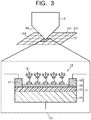
- the detector 10, as illustrated in Fig. 3 includes a detection surface sectioned into a plurality of detection cells 101. Note that Fig. 3 illustrates a state where a detection surface 10A of the detector 10 is disposed to face an end part 6a of the molecular distribution unit 6, but the disposition of the detector 10 is not limited thereto.
- the plurality of detection cells 101 each include a sensor unit 11 and a detection element 13 having organic probes 12 provided at the sensor unit 11. Fig. 3 illustrates the detection element 13 using a graphene field effect transistor (GFET) for the sensor unit 11.
- the sensor unit 11 is not limited to the GFET, and may be a field effect transistor using carbon nanotube, a surface acoustic wave sensor, and so on.
- the GFET serving as the sensor unit 11 includes a semiconductor substrate 14 that functions as a gate electrode, an insulating film 15 provided as a gate insulating layer on the semiconductor substrate 14, a graphene layer 16 provided as a channel on the insulating film 15, a source electrode 17 provided at one end of the graphene layer 16, and a drain electrode 18 provided at the other end of the graphene layer 16.
- the organic probes 12 are provided on the graphene layer 16 of the GFET 11.
- An organic compound selectively bonding to the substance to be detected 2 is used for the organic probe 12.
- the substances to be detected 2 that are led into the detector 10 are captured by the organic probes 12 on the graphene layer 16. Some impurities 4 cannot obtain an interaction with the organic probes 12, and are not captured by the detection element 13. Electrons transfer from the substance to be detected 2 captured by the organic probe 12 to the GFET 11, thereby electrical detection is performed. In this way, the target substance to be detected 2 is selectively detected.
- An organic matter forming the organic probe 12 has a property of dissolving in a solvent.
- the organic probe 12 can be installed at the graphene layer 16 by applying a solution obtained by dissolving the organic matter in a solvent to the graphene layer 16.
- the organic probe 12 preferably has a portion having such a structure as a pyrene ring.
- a molecule having such a structure as the pyrene ring interacts with a hexagonally shaped ⁇ electron system formed by carbon of the graphene, and forms an interaction state of what is called ⁇ - ⁇ stacking.
- Low-concentration probe molecules are dissolved in a solvent and the resultant is applied to the graphene, and thereby the ⁇ - ⁇ stacking is formed between the pyrene ring and the graphene and the probe molecules are aligned on the graphene to be fixed.
- the organic probe 12 can be installed on the graphene layer 16.
- the organic compounds forming the organic probe 12 will be described in detail later.
- the graphene layer 16 may be formed of a stack composed of about five graphene layers or less as well as the single layer structure of graphene.
- the substance to be detected 2 flying in the vicinity of the organic probe 12 is attracted to the organic probe 12 by hydrogen bonding force, or comes into contact with the organic probe 12 in some cases.
- an interchange of electrons occurs with the organic probe 12 and the organic probe 12 transmits an electrical change to the graphene layer 16 being in contact therewith.
- the electrical change transmitted from the organic probe 12 to the graphene layer 16 disturbs the flow of electricity between the source electrode 17 and the drain electrode 18, and thus the GFET 11 functions as a sensor.
- the GFET 11 using the graphene layer 16 as a channel even an extremely slight electrical change appears significantly as an output. As a result, it is possible to constitute the highly sensitive detection element 13.
- the sensor using the GFET 11 also has a tendency that electric current flows between the source electrode 17 and the drain electrode 18 without application of voltage to the gate electrode 14 because the graphene has a property as a zero-gap semiconductor.
- the GFET 11 functions as a sensor as it is.
- the GFET 11 applies electric current between the source electrode 17 and the drain electrode 18 in a state of applying voltage to the gate electrode 14, and observes an electrical change of the gate electrode 14 when the organic probe 12 captures the substance to be detected 2.
- the function as the sensor is further increased.
- the sensor using the GFET 11 is regarded as the most sensitive FET sensor, and can improve sensitivity about three times as compared to a sensor using a carbon nanotube.
- using the detection element 13 in which the GFET 11 and the organic probes 12 are combined enables higher sensitive detection of the substance to be detected 2.
- Fig. 3 illustrates the detection surface 10A on which the plurality of detection cells 101 are arranged in a grid pattern (an array pattern), but is not necessarily limited thereto.
- the plurality of detection cells 101 may be arranged linearly. At least some of the organic probes 12 provided at the graphene layers 16 of the plurality of detection cells 101 are different in bond strength with the substance to be detected 2. That is, the plurality of detection cells 101 include a plurality of the organic probes 12 different in the bond strength with the substance to be detected 2. All the organic probes 12 may be different in the bond strength with the substance to be detected 2, or some of the organic probes 12 may be different in the bond strength with the substance to be detected 2.
- Fig. 4A illustrates a grid-shaped sensor in which the detection surface 10A of the detector 10 is sectioned into four detection cells 101, that is a detection cell A, a detection cell B, a detection cell C, and a detection cell D. At least in some of the detection cells A to D, different types of the organic probes 12, that is the plurality of organic probes 12 different in the bond strength with the substance to be detected 2, are provided. The plurality of organic probes 12 each have an interaction with the substance to be detected 2, but are different in working strength (the bond strength) with the substance to be detected 2, and thus detection signals are different in intensity.
- Fig. 4B illustrates detection signals of the detection cells A to D. The detection signals from the detection cells A to D are different in signal intensity respectively due to the bond strength of the organic probe 12 with the substance to be detected 2.
- the signals detected in the detection cells A to D are sent to the discriminator 20 to be signal-processed.
- the discriminator 20 converts each of the detection signals from the detection cells A to D into intensity and analyzes signal patterns based on intensity differences of these detection signals (for example, four detection signal patterns illustrated in Fig. 4B ).
- the discriminator 20 stores therein signal patterns according to a substance to be detected and compares these signal patterns with the signal patterns detected in the detection cells A to D, to thereby discriminate the substance to be detected 2 detected in the detector 10.
- Such a signal process is called a pattern recognition method here.
- the pattern recognition method enables detection and discrimination of the substance to be detected 2 by signal patterns peculiar to the substance to be detected like a dactyloscopy, for example. Accordingly, selective and higher sensitive detection of a gas component (the substance to be detected 2) having an extremely low concentration in the order of ppt to ppb is enabled.
- DMMP dimethyl methylphosphonate
- organophosphorus pesticides which are used often, such as malathion, chlorpyrifos, and diazinon.
- discrimination by such signal patterns as illustrated in Fig. 4B is effective.
- the signal patterns detected in the detection cells A to D are different according to the above-described respective substances, application of the pattern recognition method enables selective and higher sensitive detection of the detection target substance even when an impurity that has a similar molecular weight and a similar constituent element is mixed.
- An organic compound forming the organic probe 12 has a hydroxy group (-OH) as a reactive group with respect to the substance to be detected 2. However, only the OH group hardly reacts with the gas component. Thus, for the purpose of enhancing a hydrogen bonding property, an organic compound where a functional group (a neighboring group) excellent in an inductive effect is introduced to a neighboring portion of the OH group is used.
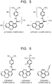
- the plurality of organic probes 12 used for the plurality of detection cells A to D of the molecular detection apparatus 1 include an organic probe made of an organic compound having the OH group as the reactive group and at least one neighboring group which is disposed neighboring to the reactive group and is selected from the cyano group and the nitro group. Typical examples of such organic compounds forming the organic probe as stated above are illustrated in Fig. 5 .
- an organic compound 1 has the cyano group (-CN) as the neighboring group of the reactive group (OH group), and an organic compound 2 has the nitro group (-NO 2 ) as the neighboring group of the reactive group (OH group).
- the organic compound forming the organic probe 12 includes a head portion HS having the reactive group and the neighboring group.
- the head portion HS is preferably a monovalent aromatic hydrocarbon group having the OH group and at least one neighboring group selected from the CN group and the NO 2 group, and more preferably a phenyl group having an alkyl group (carbon number: approximately 1 to 5) where the OH group and the CN group or the NO 2 group are bonded to the same carbon. It is not excluded that the aromatic hydrocarbon group (phenyl group) forming the head portion HS may have a substituent such as halogen and the alkyl group in addition to the reactive group and the neighboring group.
- the organic compound forming the organic probe preferably has further a base portion BS serving as an installation portion for the graphene layer 16 or the like, and a connecting portion CS connecting the head portion HS and the base portion BS.
- the base portion BS is preferably a monovalent substituted or unsubstituted polycyclic aromatic hydrocarbon group having a polycyclic structure such as a pyrene ring, an anthracene ring, a naphthacene ring, or a phenanthrene ring, and more preferably the substituted or unsubstituted pyrene group.
- the connecting portion CS is a bivalent group, and it may be an alkylene group such as a methylene group or an ethylene group.
- cyanohydrin having the OH group and the CN group and derivatives thereof there can be cited cyanohydrin having the OH group and the CN group and derivatives thereof, and it is preferably the cyanohydrin derivative in consideration of the above-described head portion HS, connecting portion CS, and base portion BS.
- the cyanohydrin derivative can be obtained by, for example, reacting hydrogen cyanide (HCN), potassium cyanide (KCN), and so on with aromatic hydrocarbon having an aldehyde group (-CHO).
- the organic compound having the OH group and the NO 2 group can be obtained by, for example, a nitroaldol reaction.
- a manufacturing method of the organic compound forming the organic probe is not particularly limited, and it is possible to appropriately select a synthesis reaction in accordance with a target compound structure.
- the organic compound forming the organic probe 12 is required to have the reactive group (OH group) and the neighboring group as described above.
- the substituent (neighboring group) disposed neighboring to the reactive group (OH group) for example, there is known an alkyl group which is substituted by fluorine atoms such as a trifluoromethyl group (-CF 3 ) or a hexafluoroethyl group (-C 2 F 5 ).
- a structure having such a substituted alkyl group there can be cited a 1,1,1,3,3,3-hexafluoro-2-phenyl-2-propanol structure (a structure A), an ⁇ -trifluoromethylbenzyl alcohol structure (a structure B), and so on.
- a degree of bonding with the substance to be detected 2 by the organic probe 12 can also be adjusted by the number of reactive groups (OH groups).
- OH groups reactive groups
- a density of the organic probes 12 installed on the detection cell 101 may be adjusted.
- the organic probes 12 are installed on the graphene layer 16 under a state where, for example, an organic compound which does not have the reactive group (OH group) and have only the base portion BS such as the pyrene ring having the interaction with the graphene layer 16 such as an organic compound 5 illustrated in Fig. 6 is mixed with the organic compound 3 or the organic compound 4 so as to change the density of the organic probes 12.
- the organic probe 12 formed of the organic compound having the functional group containing nitrogen such as the cyano group (CN group) and the nitro group (NO 2 group) as the above-described neighboring group (the organic compound 1, the organic compound 2, and so on illustrated in Fig. 5 ) is used. It is possible to change the bond strength between the organic probe 12 and the substance to be detected 2 by substituting the neighboring group of the reactive group (OH group) into a substance other than fluorine. Since the cyano group (CN group) and the nitro group (NO 2 group) are also excellent in the inductive effect, the function of the reactive group (OH group) can be enhanced.
- the organic probe formed of the organic compound having the cyano group or the nitro group as the neighboring group is used, and thereby, it is possible to diversify the bond strength difference between the organic probe 12 and the substance to be detected 2. Accordingly, it is possible to enable high-definition signal pattern based on the intensity difference of the detection signal of the substance to be detected 2 by the detection cell 101, and to enhance the detection accuracy of the substance to be detected 2. Further, it becomes possible to correspond to various kinds of substances to be detected 2.
- Detection and discrimination results of the substance to be detected 2 obtained by the molecular detection apparatus 1 may be transmitted over information network to be utilized.
- Fig. 8 illustrates the molecular detection apparatus 1 with an information processing unit 30 attached thereto or provided internally, the information processing unit 30 including at least one function selected from a function of transmitting detection information of the substance to be detected 2 over the information network and a function of checking between the detection information and reference information obtained from the information network.
- the information processing unit 30 includes an information transmitting unit 31 transmitting detection information of the substance to be detected 2, an information receiving unit 32 receiving reference information, and an information checking unit 33 checking between the detection information and the reference information.
- the information processing unit 30 may have only one of the information transmitting function, or the information receiving and information checking functions.
- the information transmitting unit 31 transmits the detection information of the substance to be detected 2 to an information user over a network N.
- the information receiving unit 32 obtains the reference information over the network N.
- the information checking unit 33 checks the obtained reference information with the detection information.
- Information is obtained from the external network N to be referred to, and thereby a function of carrying a lot of information and analyzing them can be replaced with an alternative externally. Consequently, further miniaturization of the molecular detection apparatus 1 is enabled to increase portability. Further, using the network N also makes it possible to obtain new signal patterns used by the pattern recognition method immediately. On the information receiving side, it is possible to take a next action based on this information.
- the molecular detection apparatus 1 it is possible to use the molecular detection apparatus 1 in such a way that the portable molecular detection apparatus 1 is disposed at respective places and data to be obtained are collected from the respective places to be analyzed, and then the analyzed data are utilized for evacuation guidance under abnormal circumstances or the like.
- the network N and the molecular detection apparatus 1 are combined, and thereby a lot of use ways, which were not able to be achieved conventionally, are created and its industrial value improves.
- the molecular detection apparatus 1 of the arrangement the selective and higher sensitive detection of the gas component molecule having the extremely low concentration in the order of ppt to ppb is possible. Further, the detection sensitivity and the detection accuracy are enhanced by using the detector 10 and the discriminator 20, and thereby, it becomes possible to reduce the molecular detection apparatus 1 in size. Accordingly, it becomes possible to provide the molecular detection apparatus 1 where the portability and the detection accuracy are both enabled. It is possible for the molecular detection apparatus 1 according to the arrangement to effectively exert the functions at various sites such as at a disaster site or a site at which an act of terrorism occurs or the like.
- dimethyl methylphosphonate (DMMP, molecular weight: 124) which is a toxic organophosphorus material, is used as a substance to be detected.
- DMMP being the substance to be detected is liquid at room temperature, has a flash point of 69°C, and a boiling point of 181°C.
- a vapor pressure is 79 Pa (at 20°C). It has a property stable in liquid state at room temperature. In order to vaporize such liquid, it is general to increase a temperature to accelerate vaporization.
- aerating inert gas in the liquid to increase a surface area of the liquid what is called bubbling
- a method accelerating vaporization by spraying gas on a liquid surface and so on as a more simple method.
- a concentration of the gas obtained as stated above is approximately ppm (parts per million) to ppb (parts per billion), and the concentration is lowered by mixing the gas with the inert gas.
- the concentration of DMMP contained in the aerated nitrogen (N 2 ) gas by adopting the bubbling in the example is set to 10 ppm.
- the DMMP concentration is lowered by mixing second nitrogen gas with the gas.
- a gas concentration adjusting system is set such that the concentration can be arbitrary adjusted to be 100 ppt (parts per trillion) or more. It is difficult to check the concentration of gas of low density at several ppb or less with a mass spectrometer, and therefore, a collection tube is used. Since the collection tube adsorbs and condenses the gas component as time proceeds, it is possible to estimate the concentration of the original gas component by separating the gas component after the collection to be measured with the mass spectrometer.
- a detection element in which a GFET and an organic probe are combined is prepared as follows.
- a graphene layer is formed by transferring graphite onto a substrate by an exfoliation method or by depositing graphene on a metal surface by means of a chemical vapor deposition method (CVD).
- a single layer or a plurality of layers of graphene deposited on the metal surface are transferred onto a polymer film, and the resultant polymer film is transferred again onto a desired semiconductor substrate for field effect transistor (FET) fabrication.
- FET field effect transistor
- graphene is formed on a surface of a copper foil by CVD with flowing of a methane gas under a condition of approximately 1000°C.
- a polymethyl methacrylate film is applied at 4000 rpm by a spin coating method, and the opposite surface of the copper foil film is etched with an ammonium persulfate 0.1 M solution, and thereby a graphene film floating in the solution is recovered.
- the graphene film is transferred onto the polymethyl methacrylate film side.
- a surface of the graphene film is sufficiently cleaned, and then this is transferred onto a silicon substrate again.
- the redundant polymethyl methacrylate film is dissolved with acetone to be removed.
- a resist is applied onto the graphene transferred onto the silicon substrate to undergo patterning, and a pattern with a 10 ⁇ m electrode interval is formed by oxygen plasma.
- Electrodes are deposited to form an FET structure on which a source electrode and a drain electrode are provided.
- the graphene is disposed on an oxide film formed on the surface of the silicon substrate and an FET type sensor structure is formed in which the graphene is sandwiched between the source electrode and the drain electrode and the silicon substrate side is set as the gate electrode.
- the graphene sensor has a tendency that electric current flows between the source and the drain without application of voltage to the gate electrode because the graphene has a property as a zero-gap semiconductor. Thus, it functions as a sensor as it is, and a detection signal can be obtained by collision of substances with the graphene.
- electric current is applied between the source and the drain in a state of applying the gate voltage, and an electrical change of the gate electrode when the substances are in contact is observed.
- organic probes are provided on the surface of the graphene.
- the organic probe is installed in a manner that an organic compound is dissolved in a methanol solution at a concentration of 10 nM and a graphene sensor surface is immersed in the resultant solution for several minutes.
- the organic compound 1, the organic compound 2, and the organic compound 3 described above are used for the organic probes.
- Working force of the organic probe with respect to the substance to be detected changes depending on an amount of the reactive group (OH group). Accordingly, an amount of the organic probe may be adjusted by mixing the organic compound forming the organic probe with the above-described organic compound 5 which does not have the reactive group (OH group).
- a detection surface of a detector four detection cells A to D are provided on a detection surface of a detector, and the organic probes different from one another are respectively installed.
- the organic compound 3 is installed at the detection cell A as the organic probe.
- the organic compound 1 is installed at the detection cell B as the organic probe.
- the organic compound 2 is installed at the detection cell C as the organic probe.
- the organic compound 5 which does not have the reactive group is installed at the detection cell D to make it a standard cell indicating a reference.
- the organic compound 1, the organic compound 2, and the organic compound 3 are respectively different in the bond strength with the substance to be detected (DMMP). Accordingly, it is possible to detect the substance to be detected (DMMP) by the detection cell according to the above-described pattern recognition method.
- Gas containing DMMP as the substance to be detected is introduced into the detector including the above-described detection cells A to D to perform the detection of DMMP.
- the substances to be detected are respectively captured by the organic probes in the detection cells A to D. Since the organic probes in the detection cells A to D are respectively different in the bond strength with the substance to be detected, signals to be detected by the gate electrodes are also different respectively. Results of detection by the detection cells A to D are sent to a discriminator that processes signals, and are each converted into intensity. Although a method of converting into intensity can be variously considered, a value calculated from an area defined by PI, P2 and P3 being a tip of a peak in Fig. 10 is set as the intensity. However, the conversion method is not necessarily limited to this method.
- recognition results are output as a relative intensity display.
- Fig. 9B illustrates a result where measurement is performed while setting DMMP as the substance to be detected
- Fig. 9C illustrates a result where measurement is performed while setting diphenyl chlorophosphate (dPCP) as the substance to be detected
- Fig. 9D illustrates a result where DMMP is detected by a detector in which an equimolar mixture of the organic compound 3 and the organic compound 5 is installed at the detection cell D as the organic probe.
- the intensities different by cells are collectively analyzed to obtain a peculiar signal intensity pattern by the substance to be detected according to the pattern recognition.
- the substance to be detected is discriminated based on the signal pattern depending on the signal intensity difference as stated above, and thereby, it is possible to selectively and high sensitively detect the substance to be detected (gas component molecule) having an extremely low concentration in the order of ppt to ppb. Besides, it is possible to further improve the detection sensitivity and the detection accuracy of the substance to be detected (gas component molecule) by increasing the kinds of the organic compounds forming the organic probes. Besides, it is possible to further diversify the peculiar signal patterns by increasing the number of detection cells and installing the organic probes formed of a plurality of organic compounds in one detection cell in addition to increasing the kinds of the organic compounds. Accordingly, it becomes possible to enable the improvement in the detection accuracy of the substance to be detected, and to detect various kinds of substances to be detected 2.
- organophosphorus materials captured by the organic probe are released after the passage of time, but a part thereof is fixed. After a few times of sensing, it becomes necessary to release the organophosphorus materials being the fixed substances to be detected.
- Gas where 3% of hydrogen at an explosion limit or less is mixed with argon is filled in a firing furnace to be heated, and the substances to be detected which are fixed to the organic probe surface of the sensor are released. This operation is called as reactivation (refresh). It is desired to apply a temperature at approximately 200 to 400°C for 20 to 30 minutes for the refresh. It is appropriately set in consideration of kinds and disposition states of the organic probes.
Landscapes
- Chemical & Material Sciences (AREA)
- Life Sciences & Earth Sciences (AREA)
- Health & Medical Sciences (AREA)
- Engineering & Computer Science (AREA)
- Pathology (AREA)
- General Physics & Mathematics (AREA)
- Immunology (AREA)
- General Health & Medical Sciences (AREA)
- Biochemistry (AREA)
- Physics & Mathematics (AREA)
- Analytical Chemistry (AREA)
- Electrochemistry (AREA)
- Chemical Kinetics & Catalysis (AREA)
- Molecular Biology (AREA)
- Microelectronics & Electronic Packaging (AREA)
- Combustion & Propulsion (AREA)
- Food Science & Technology (AREA)
- Medicinal Chemistry (AREA)
- Nanotechnology (AREA)
- Computer Hardware Design (AREA)
- Investigating Or Analyzing Materials By The Use Of Electric Means (AREA)
Abstract
Description
- Arrangements described herein generally relate to a molecular detection apparatus, a molecular detection method, and an organic probe.
- A water heater or the like for household use is provided with an apparatus that detects carbon monoxide generated when incomplete combustion occurs and notifies the risk thereof at an early stage. Such a gas component considerably affects a human body. According to the guidelines from LP gas safety committee, it is set that a carbon monoxide concentration of approximately 200 ppm (parts per million) causes headaches. Although various methods have been known as a method of detecting a gas component having a relatively higher concentration, the detection methods have been limited for detecting the gas component having a concentration in the order of ppb (parts per billion) to ppt (parts per trillion), which corresponds to an extremely low concentration.
- At a disaster site or a site at which an act of terrorism occurs or the like, it has been desired to sense the risk in advance by detecting an extremely small amount of the gas component. The gas component having an extremely low concentration is often detected by use of large equipment in research facilities. In this case, a large sized installation type apparatus, which is expensive and has large weight and volume, such as a gas chromatography or a mass spectrometer is required. Under such circumstances, it has been required to provide an apparatus that is capable of detecting the gas component having the extremely low concentration in real time, in other words, an apparatus that has a smaller weight and volume and a better portability and enables selective and higher sensitive detection of the gas component having the extremely low concentration in the order of ppt to ppb.
- As a detection element for the gas component having a low concentration, for example, an element has been known that has a conductive layer in which a surface of a carbon nanostructure is surface modified with a substance that selectively reacts with or adsorbs a specific substance and measures a potential difference or the like that changes depending on the gas component that has adhered to the surface of the carbon nanostructure. In such a detection element, there is a possibility that it is impossible to accurately detect a detection target gas component when a component or the like similar to the detection target gas component is mixed in the gas obtained from, for example, the air as impurities. Besides, the detection substances are limited to alcohol, nitrogen oxide, and so on whose molecular structure is simple.
-
- Reference 1:
JP-A 2010-019688 - Reference 2:
JP-A 2010-139269 - Reference 3:
JP-A 2015-515622 - An object to be solved by the arrangements is to provide a molecular detection apparatus enabling selective and higher sensitive detection of a gas component having an extremely low concentration, a molecular detection method, and an organic probe.
- A molecular detection apparatus according to an arrangement includes: a detector which includes a plurality of detection cells having at least an organic probe containing a cyano group or a nitro group as a neighboring group of a reactive group; and a discriminator which discriminates a substance to be detected by signal patterns of the plurality of detection cells.
-
-
Fig. 1 is a block diagram illustrating a molecular detection apparatus according to an arrangement. -
Fig. 2 is a block diagram illustrating a modified example of the molecular detection apparatus illustrated inFig. 1 . -
Fig. 3 is a view illustrating a configuration of a detector in the molecular detection apparatus according to the arrangement. -
Fig. 4A is a view illustrating an example of a plurality of detection cells of the molecular detection apparatus according to the arrangement. -
Fig. 4B is a view illustrating an example of a detection result of a substance to be detected by the plurality of detection cells illustrated inFig. 4A . -
Fig. 5 is a view illustrating a first example of an organic compound used for an organic probe in the detector of the molecular detection apparatus according to the arrangement. -
Fig. 6 is a view illustrating a second example of the organic compound used for the organic probe in the detector of the molecular detection apparatus according to the arrangement. -
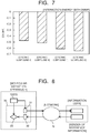
Fig. 7 is a view illustrating interaction energy between DMMP being the organic compound used for the organic probe in the detector of the molecular detection apparatus according to the arrangement. -
Fig. 8 is a view illustrating an information processing unit in the molecular detection apparatus according to the arrangement. -
Fig. 9A is a view illustrating an example of a plurality of detection cells of the molecular detection apparatus of an example. -
Fig. 9B is a view illustrating a first example of a detection result of a substance to be detected by the plurality of detection cells illustrated inFig. 9A . -
Fig. 9C is a view illustrating a second example of the detection result of the substance to be detected by the plurality of detection cells illustrated inFig. 9A . -
Fig. 9D is a view illustrating a third example of the detection result of the substance to be detected by the plurality of detection cells illustrated inFig. 9A . -
Fig. 10 is a view illustrating an example of a detected waveform of a substance to be detected by the molecular detection apparatus according to the example. - Hereinafter, there will be explained a molecular detection apparatus and a molecular detection method according to arrangements with reference to the drawings. In the arrangements, substantially the same constituent elements are denoted by the same reference signs and a description thereof will be omitted in some case. The drawings are schematic, and a relation of the thickness and the planar dimension of each part, a thickness ratio among parts, and so on may differ from actual ones.
-
Fig. 1 is a block diagram illustrating a molecular detection apparatus according to the arrangement. Amolecular detection apparatus 1 illustrated inFig. 1 is, for example, an apparatus that detects, fromdetection target gas 3 containing substances to be detected 2 generated from a gas generation source, the substance to be detected 2, and includes adetector 10 and adiscriminator 20. Thetarget gas 3 containing the substances to be detected 2 is, first sent to thedetector 10 of themolecular detection apparatus 1. Here, thedetection target gas 3 sometimes contains, as an impurity, substances having a molecular weight, a molecular structure or the like similar to those of the substance to be detected 2. Further, as illustrated inFig. 2 , the substances to be detected 2 drifting in the air often exist in a state where the substances to be detected 2 are mixed with various foreign substances 4 (4a and 4b) such as odor components and fine particles. From those perspectives, as illustrated inFIG. 2 , thedetection target gas 3 may be sent to thedetector 10 of themolecular detection apparatus 1 after being preprocessed by afilter unit 5, amolecular distribution unit 6, and the like beforehand. - For the
filter unit 5 out of the devices of preprocess, a generally-used moderate-to-high performance filter or the like is used. Thefilter unit 5 removes particulate substances such as fine particles contained in thedetection target gas 3. Thedetection target gas 3, from which the particulate substances are removed in thefilter unit 5, is then sent to themolecular distribution unit 6. As themolecular distribution unit 6, there can be exemplified an apparatus that ionizes thedetection target gas 3 to form an ionized substance group, applies voltage to the ionized substance group to allow the ionized substance group to fly at a speed proportional to the mass thereof, and separates an ionized substance of the substance to be detected 2 from the ionized substance group using a flight speed based on the difference in mass among ionized substances and a time of flight based on the flight speed. As themolecular distribution unit 6 as above, a device including an ionization unit, a voltage application unit, and a time-of-flight separation unit is used. - The
target gas 3 containing the substances to be detected 2 is led to thedetector 10 directly, or after being preprocessed by the devices such as thefilter unit 5 and themolecular distribution unit 6. Thedetector 10, as illustrated inFig. 3 , includes a detection surface sectioned into a plurality ofdetection cells 101. Note thatFig. 3 illustrates a state where adetection surface 10A of thedetector 10 is disposed to face anend part 6a of themolecular distribution unit 6, but the disposition of thedetector 10 is not limited thereto. The plurality ofdetection cells 101 each include asensor unit 11 and adetection element 13 havingorganic probes 12 provided at thesensor unit 11.Fig. 3 illustrates thedetection element 13 using a graphene field effect transistor (GFET) for thesensor unit 11. Thesensor unit 11 is not limited to the GFET, and may be a field effect transistor using carbon nanotube, a surface acoustic wave sensor, and so on. - The GFET serving as the
sensor unit 11 includes asemiconductor substrate 14 that functions as a gate electrode, an insulatingfilm 15 provided as a gate insulating layer on thesemiconductor substrate 14, agraphene layer 16 provided as a channel on the insulatingfilm 15, asource electrode 17 provided at one end of thegraphene layer 16, and adrain electrode 18 provided at the other end of thegraphene layer 16. Theorganic probes 12 are provided on thegraphene layer 16 of theGFET 11. An organic compound selectively bonding to the substance to be detected 2 is used for theorganic probe 12. The substances to be detected 2 that are led into thedetector 10 are captured by theorganic probes 12 on thegraphene layer 16. Someimpurities 4 cannot obtain an interaction with theorganic probes 12, and are not captured by thedetection element 13. Electrons transfer from the substance to be detected 2 captured by theorganic probe 12 to theGFET 11, thereby electrical detection is performed. In this way, the target substance to be detected 2 is selectively detected. - An organic matter forming the
organic probe 12 has a property of dissolving in a solvent. Thus, theorganic probe 12 can be installed at thegraphene layer 16 by applying a solution obtained by dissolving the organic matter in a solvent to thegraphene layer 16. In order to easily obtain an interaction with graphene, theorganic probe 12 preferably has a portion having such a structure as a pyrene ring. A molecule having such a structure as the pyrene ring interacts with a hexagonally shaped π electron system formed by carbon of the graphene, and forms an interaction state of what is called π-π stacking. Low-concentration probe molecules are dissolved in a solvent and the resultant is applied to the graphene, and thereby the π-π stacking is formed between the pyrene ring and the graphene and the probe molecules are aligned on the graphene to be fixed. By using such a self-alignment action, theorganic probe 12 can be installed on thegraphene layer 16. The organic compounds forming theorganic probe 12 will be described in detail later. - When the substances to be detected 2 are captured by the
organic probes 12 provided on thegraphene layer 16, an output from theGFET 11 changes. The case of a single layer of graphene means that there is zero gap, and thus, thesource electrode 17 and thedrain electrode 18 are continuously electrified normally. When the number of graphene layers increases to two or three layers, a band gap is generated, but such a band gap in an actual system is relatively smaller than that considered from a strict theoretical value. When thegate insulating layer 15 has a dielectric constant approximately similar to that of a silicon oxide film, thesource electrode 17 and thedrain electrode 18 are often continuously electrified. Thus, thegraphene layer 16 may be formed of a stack composed of about five graphene layers or less as well as the single layer structure of graphene. - The substance to be detected 2 flying in the vicinity of the
organic probe 12 is attracted to theorganic probe 12 by hydrogen bonding force, or comes into contact with theorganic probe 12 in some cases. When the contact with the substance to be detected 2 occurs, an interchange of electrons occurs with theorganic probe 12 and theorganic probe 12 transmits an electrical change to thegraphene layer 16 being in contact therewith. The electrical change transmitted from theorganic probe 12 to thegraphene layer 16 disturbs the flow of electricity between thesource electrode 17 and thedrain electrode 18, and thus theGFET 11 functions as a sensor. With theGFET 11 using thegraphene layer 16 as a channel, even an extremely slight electrical change appears significantly as an output. As a result, it is possible to constitute the highlysensitive detection element 13. The sensor using theGFET 11 also has a tendency that electric current flows between thesource electrode 17 and thedrain electrode 18 without application of voltage to thegate electrode 14 because the graphene has a property as a zero-gap semiconductor. Thus, theGFET 11 functions as a sensor as it is. However, normally, theGFET 11 applies electric current between thesource electrode 17 and thedrain electrode 18 in a state of applying voltage to thegate electrode 14, and observes an electrical change of thegate electrode 14 when theorganic probe 12 captures the substance to be detected 2. - In the detection of the substance to be detected 2 performed by the above-described
detection element 13, as the transfer of electrons from the substance to be detected 2 that is captured by theorganic probe 12 to theGFET 11 is higher, the function as the sensor is further increased. The sensor using theGFET 11 is regarded as the most sensitive FET sensor, and can improve sensitivity about three times as compared to a sensor using a carbon nanotube. Thus, using thedetection element 13 in which theGFET 11 and theorganic probes 12 are combined enables higher sensitive detection of the substance to be detected 2. -
Fig. 3 illustrates thedetection surface 10A on which the plurality ofdetection cells 101 are arranged in a grid pattern (an array pattern), but is not necessarily limited thereto. The plurality ofdetection cells 101 may be arranged linearly. At least some of theorganic probes 12 provided at the graphene layers 16 of the plurality ofdetection cells 101 are different in bond strength with the substance to be detected 2. That is, the plurality ofdetection cells 101 include a plurality of theorganic probes 12 different in the bond strength with the substance to be detected 2. All theorganic probes 12 may be different in the bond strength with the substance to be detected 2, or some of theorganic probes 12 may be different in the bond strength with the substance to be detected 2. -
Fig. 4A illustrates a grid-shaped sensor in which thedetection surface 10A of thedetector 10 is sectioned into fourdetection cells 101, that is a detection cell A, a detection cell B, a detection cell C, and a detection cell D. At least in some of the detection cells A to D, different types of theorganic probes 12, that is the plurality oforganic probes 12 different in the bond strength with the substance to be detected 2, are provided. The plurality oforganic probes 12 each have an interaction with the substance to be detected 2, but are different in working strength (the bond strength) with the substance to be detected 2, and thus detection signals are different in intensity.Fig. 4B illustrates detection signals of the detection cells A to D. The detection signals from the detection cells A to D are different in signal intensity respectively due to the bond strength of theorganic probe 12 with the substance to be detected 2. - The signals detected in the detection cells A to D are sent to the
discriminator 20 to be signal-processed. Thediscriminator 20 converts each of the detection signals from the detection cells A to D into intensity and analyzes signal patterns based on intensity differences of these detection signals (for example, four detection signal patterns illustrated inFig. 4B ). Thediscriminator 20 stores therein signal patterns according to a substance to be detected and compares these signal patterns with the signal patterns detected in the detection cells A to D, to thereby discriminate the substance to be detected 2 detected in thedetector 10. Such a signal process is called a pattern recognition method here. The pattern recognition method enables detection and discrimination of the substance to be detected 2 by signal patterns peculiar to the substance to be detected like a dactyloscopy, for example. Accordingly, selective and higher sensitive detection of a gas component (the substance to be detected 2) having an extremely low concentration in the order of ppt to ppb is enabled. - Application of the above-described pattern recognition method enables selective and higher sensitive detection and discrimination of the substance to be detected 2 even when impurities are mixed in the
detection target gas 3 that is led to thedetector 10. For example, in the case when the substance to be detected 2 is dimethyl methylphosphonate (DMMP, molecular weight: 124), which is a typical material for a toxic organophosphorus compound, there exist agricultural chemicals containing phosphoric acid such as dichlorvos having a similar chemical structure and organophosphorus pesticides, which are used often, such as malathion, chlorpyrifos, and diazinon. In order to prevent an erroneous detection of these substances, discrimination by such signal patterns as illustrated inFig. 4B is effective. In other words, since the signal patterns detected in the detection cells A to D are different according to the above-described respective substances, application of the pattern recognition method enables selective and higher sensitive detection of the detection target substance even when an impurity that has a similar molecular weight and a similar constituent element is mixed. - Next, there is described in detail the
organic probe 12 to be used for the plurality of detection cells A to D of themolecular detection apparatus 1 according to the arrangement. An organic compound forming theorganic probe 12 has a hydroxy group (-OH) as a reactive group with respect to the substance to be detected 2. However, only the OH group hardly reacts with the gas component. Thus, for the purpose of enhancing a hydrogen bonding property, an organic compound where a functional group (a neighboring group) excellent in an inductive effect is introduced to a neighboring portion of the OH group is used. The plurality oforganic probes 12 used for the plurality of detection cells A to D of themolecular detection apparatus 1 include an organic probe made of an organic compound having the OH group as the reactive group and at least one neighboring group which is disposed neighboring to the reactive group and is selected from the cyano group and the nitro group. Typical examples of such organic compounds forming the organic probe as stated above are illustrated inFig. 5 . - Between the organic compounds illustrated in
Fig. 5 , anorganic compound 1 has the cyano group (-CN) as the neighboring group of the reactive group (OH group), and anorganic compound 2 has the nitro group (-NO2) as the neighboring group of the reactive group (OH group). As illustrated inFig. 5 , the organic compound forming theorganic probe 12 includes a head portion HS having the reactive group and the neighboring group. The head portion HS is preferably a monovalent aromatic hydrocarbon group having the OH group and at least one neighboring group selected from the CN group and the NO2 group, and more preferably a phenyl group having an alkyl group (carbon number: approximately 1 to 5) where the OH group and the CN group or the NO2 group are bonded to the same carbon. It is not excluded that the aromatic hydrocarbon group (phenyl group) forming the head portion HS may have a substituent such as halogen and the alkyl group in addition to the reactive group and the neighboring group. - The organic compound forming the organic probe preferably has further a base portion BS serving as an installation portion for the
graphene layer 16 or the like, and a connecting portion CS connecting the head portion HS and the base portion BS. The base portion BS is preferably a monovalent substituted or unsubstituted polycyclic aromatic hydrocarbon group having a polycyclic structure such as a pyrene ring, an anthracene ring, a naphthacene ring, or a phenanthrene ring, and more preferably the substituted or unsubstituted pyrene group. The connecting portion CS is a bivalent group, and it may be an alkylene group such as a methylene group or an ethylene group. The connecting portion CS is preferably an ether bond (-O-), an ester bond (-C(=O)O-), a carbonyl bond (-CO-), an amide bond (-NH-CO-), an imide bond (-CO-NH-CO-), and so on, and is more preferably the amide bond. - As concrete examples of the above-described organic compounds forming the organic probe, there can be cited cyanohydrin having the OH group and the CN group and derivatives thereof, and it is preferably the cyanohydrin derivative in consideration of the above-described head portion HS, connecting portion CS, and base portion BS. The cyanohydrin derivative can be obtained by, for example, reacting hydrogen cyanide (HCN), potassium cyanide (KCN), and so on with aromatic hydrocarbon having an aldehyde group (-CHO). Besides, the organic compound having the OH group and the NO2 group can be obtained by, for example, a nitroaldol reaction. Note that a manufacturing method of the organic compound forming the organic probe is not particularly limited, and it is possible to appropriately select a synthesis reaction in accordance with a target compound structure.
- Incidentally, the organic compound forming the
organic probe 12 is required to have the reactive group (OH group) and the neighboring group as described above. As the substituent (neighboring group) disposed neighboring to the reactive group (OH group), for example, there is known an alkyl group which is substituted by fluorine atoms such as a trifluoromethyl group (-CF3) or a hexafluoroethyl group (-C2F5). As a structure having such a substituted alkyl group, there can be cited a 1,1,1,3,3,3-hexafluoro-2-phenyl-2-propanol structure (a structure A), an α-trifluoromethylbenzyl alcohol structure (a structure B), and so on. These structures have an effect of enhancing activity of the reactive group (OH group) with fluorine having a high electronegativity. Concrete examples of anorganic compound 3 where the structure A is applied and anorganic compound 4 where the structure B is applied are illustrated inFig. 6 . The bond strength with the substance to be detected 2 of theorganic compound 4 is different from that of theorganic compound 3 because the numbers of neighboring groups (CF3 groups) are different. - A degree of bonding with the substance to be detected 2 by the
organic probe 12 can also be adjusted by the number of reactive groups (OH groups). In order to change the bonding degree with the substance to be detected 2 in thedetection cell 101 where theorganic compound 3 and theorganic compound 4 are applied to theorganic probes 12, a density of theorganic probes 12 installed on thedetection cell 101 may be adjusted. Theorganic probes 12 are installed on thegraphene layer 16 under a state where, for example, an organic compound which does not have the reactive group (OH group) and have only the base portion BS such as the pyrene ring having the interaction with thegraphene layer 16 such as anorganic compound 5 illustrated inFig. 6 is mixed with theorganic compound 3 or theorganic compound 4 so as to change the density of the organic probes 12. It is possible to change an electrical variation of thegraphene layer 16 by a mixture ratio of theorganic compound 5 with theorganic compound 3 or theorganic compound 4, that is, a ratio of the reactive group (OH group), to thereby change the intensity of the detection signal by thedetection cell 101. - There is a limit in adjustment of the bond strength difference with the substance to be detected 2 by the
organic probe 12 only by the above-described adjustment of the number of neighboring groups containing the fluorine atoms and adjustment of the density of the organic compounds having the reactive group (OH group). In themolecular detection apparatus 1 according to the arrangement, theorganic probe 12 formed of the organic compound having the functional group containing nitrogen such as the cyano group (CN group) and the nitro group (NO2 group) as the above-described neighboring group (theorganic compound 1, theorganic compound 2, and so on illustrated inFig. 5 ) is used. It is possible to change the bond strength between theorganic probe 12 and the substance to be detected 2 by substituting the neighboring group of the reactive group (OH group) into a substance other than fluorine. Since the cyano group (CN group) and the nitro group (NO2 group) are also excellent in the inductive effect, the function of the reactive group (OH group) can be enhanced. - Results where interaction energy between each of the
organic compounds 1 to 4 and DMMP being a typical gas molecule is calculated by a density functional method (B3LYP/6 - 31 + G(d, p)) are illustrated inFig. 7 . It can be seen that there are differences in the interaction energy between the organic compound and DMMP due to the difference in the induction effect of the neighboring group. Theorganic probe 12 formed of the organic compound having the cyano group (CN group) or the nitro group (NO2 group) as the neighboring group can be used instead of the organic probe formed of the organic compound having a fluoroalkyl group as the neighboring group, or by being combined with such an organic probe. The organic probe formed of the organic compound having the cyano group or the nitro group as the neighboring group is used, and thereby, it is possible to diversify the bond strength difference between theorganic probe 12 and the substance to be detected 2. Accordingly, it is possible to enable high-definition signal pattern based on the intensity difference of the detection signal of the substance to be detected 2 by thedetection cell 101, and to enhance the detection accuracy of the substance to be detected 2. Further, it becomes possible to correspond to various kinds of substances to be detected 2. - Detection and discrimination results of the substance to be detected 2 obtained by the
molecular detection apparatus 1 may be transmitted over information network to be utilized.Fig. 8 illustrates themolecular detection apparatus 1 with aninformation processing unit 30 attached thereto or provided internally, theinformation processing unit 30 including at least one function selected from a function of transmitting detection information of the substance to be detected 2 over the information network and a function of checking between the detection information and reference information obtained from the information network. Theinformation processing unit 30 includes aninformation transmitting unit 31 transmitting detection information of the substance to be detected 2, aninformation receiving unit 32 receiving reference information, and aninformation checking unit 33 checking between the detection information and the reference information. Theinformation processing unit 30 may have only one of the information transmitting function, or the information receiving and information checking functions. - The
information transmitting unit 31 transmits the detection information of the substance to be detected 2 to an information user over a network N. In order to check the detection information of the substance to be detected 2 with the existing reference information, theinformation receiving unit 32 obtains the reference information over the network N. Theinformation checking unit 33 checks the obtained reference information with the detection information. Information is obtained from the external network N to be referred to, and thereby a function of carrying a lot of information and analyzing them can be replaced with an alternative externally. Consequently, further miniaturization of themolecular detection apparatus 1 is enabled to increase portability. Further, using the network N also makes it possible to obtain new signal patterns used by the pattern recognition method immediately. On the information receiving side, it is possible to take a next action based on this information. It is possible to use themolecular detection apparatus 1 in such a way that the portablemolecular detection apparatus 1 is disposed at respective places and data to be obtained are collected from the respective places to be analyzed, and then the analyzed data are utilized for evacuation guidance under abnormal circumstances or the like. The network N and themolecular detection apparatus 1 are combined, and thereby a lot of use ways, which were not able to be achieved conventionally, are created and its industrial value improves. - According to the
molecular detection apparatus 1 of the arrangement, the selective and higher sensitive detection of the gas component molecule having the extremely low concentration in the order of ppt to ppb is possible. Further, the detection sensitivity and the detection accuracy are enhanced by using thedetector 10 and thediscriminator 20, and thereby, it becomes possible to reduce themolecular detection apparatus 1 in size. Accordingly, it becomes possible to provide themolecular detection apparatus 1 where the portability and the detection accuracy are both enabled. It is possible for themolecular detection apparatus 1 according to the arrangement to effectively exert the functions at various sites such as at a disaster site or a site at which an act of terrorism occurs or the like. - In examples, dimethyl methylphosphonate (DMMP, molecular weight: 124) which is a toxic organophosphorus material, is used as a substance to be detected. DMMP being the substance to be detected is liquid at room temperature, has a flash point of 69°C, and a boiling point of 181°C. A vapor pressure is 79 Pa (at 20°C). It has a property stable in liquid state at room temperature. In order to vaporize such liquid, it is general to increase a temperature to accelerate vaporization. Though, there are adopted a method aerating inert gas in the liquid to increase a surface area of the liquid, what is called bubbling, a method accelerating vaporization by spraying gas on a liquid surface, and so on as a more simple method.
- A concentration of the gas obtained as stated above is approximately ppm (parts per million) to ppb (parts per billion), and the concentration is lowered by mixing the gas with the inert gas. The concentration of DMMP contained in the aerated nitrogen (N2) gas by adopting the bubbling in the example is set to 10 ppm. The DMMP concentration is lowered by mixing second nitrogen gas with the gas. A gas concentration adjusting system is set such that the concentration can be arbitrary adjusted to be 100 ppt (parts per trillion) or more. It is difficult to check the concentration of gas of low density at several ppb or less with a mass spectrometer, and therefore, a collection tube is used. Since the collection tube adsorbs and condenses the gas component as time proceeds, it is possible to estimate the concentration of the original gas component by separating the gas component after the collection to be measured with the mass spectrometer.
- A detection element in which a GFET and an organic probe are combined is prepared as follows. A graphene layer is formed by transferring graphite onto a substrate by an exfoliation method or by depositing graphene on a metal surface by means of a chemical vapor deposition method (CVD). A single layer or a plurality of layers of graphene deposited on the metal surface are transferred onto a polymer film, and the resultant polymer film is transferred again onto a desired semiconductor substrate for field effect transistor (FET) fabrication. For example, graphene is formed on a surface of a copper foil by CVD with flowing of a methane gas under a condition of approximately 1000°C.
- Next, a polymethyl methacrylate film is applied at 4000 rpm by a spin coating method, and the opposite surface of the copper foil film is etched with an ammonium persulfate 0.1 M solution, and thereby a graphene film floating in the solution is recovered. By doing this, the graphene film is transferred onto the polymethyl methacrylate film side. A surface of the graphene film is sufficiently cleaned, and then this is transferred onto a silicon substrate again. The redundant polymethyl methacrylate film is dissolved with acetone to be removed. A resist is applied onto the graphene transferred onto the silicon substrate to undergo patterning, and a pattern with a 10 µm electrode interval is formed by oxygen plasma. Electrodes are deposited to form an FET structure on which a source electrode and a drain electrode are provided. The graphene is disposed on an oxide film formed on the surface of the silicon substrate and an FET type sensor structure is formed in which the graphene is sandwiched between the source electrode and the drain electrode and the silicon substrate side is set as the gate electrode.
- The graphene sensor has a tendency that electric current flows between the source and the drain without application of voltage to the gate electrode because the graphene has a property as a zero-gap semiconductor. Thus, it functions as a sensor as it is, and a detection signal can be obtained by collision of substances with the graphene. However, normally, electric current is applied between the source and the drain in a state of applying the gate voltage, and an electrical change of the gate electrode when the substances are in contact is observed.
- Next, organic probes are provided on the surface of the graphene. The organic probe is installed in a manner that an organic compound is dissolved in a methanol solution at a concentration of 10 nM and a graphene sensor surface is immersed in the resultant solution for several minutes. For the organic probes, the
organic compound 1, theorganic compound 2, and theorganic compound 3 described above are used. Working force of the organic probe with respect to the substance to be detected changes depending on an amount of the reactive group (OH group). Accordingly, an amount of the organic probe may be adjusted by mixing the organic compound forming the organic probe with the above-describedorganic compound 5 which does not have the reactive group (OH group). For example, when the solution of theorganic compound 1 is used, it is possible to adjust a ratio between theorganic compound 1 and theorganic compound 5 into 1: 1 by substituting 5 nM from among 10 nM of the solution with theorganic compound 5. - In the example, as illustrated in
Fig. 9A , four detection cells A to D are provided on a detection surface of a detector, and the organic probes different from one another are respectively installed. Theorganic compound 3 is installed at the detection cell A as the organic probe. Theorganic compound 1 is installed at the detection cell B as the organic probe. Theorganic compound 2 is installed at the detection cell C as the organic probe. Theorganic compound 5 which does not have the reactive group is installed at the detection cell D to make it a standard cell indicating a reference. As described previously, theorganic compound 1, theorganic compound 2, and theorganic compound 3 are respectively different in the bond strength with the substance to be detected (DMMP). Accordingly, it is possible to detect the substance to be detected (DMMP) by the detection cell according to the above-described pattern recognition method. - Gas containing DMMP as the substance to be detected is introduced into the detector including the above-described detection cells A to D to perform the detection of DMMP. The substances to be detected are respectively captured by the organic probes in the detection cells A to D. Since the organic probes in the detection cells A to D are respectively different in the bond strength with the substance to be detected, signals to be detected by the gate electrodes are also different respectively. Results of detection by the detection cells A to D are sent to a discriminator that processes signals, and are each converted into intensity. Although a method of converting into intensity can be variously considered, a value calculated from an area defined by PI, P2 and P3 being a tip of a peak in
Fig. 10 is set as the intensity. However, the conversion method is not necessarily limited to this method. - As illustrated in
Fig. 9B to Fig. 9D , recognition results are output as a relative intensity display.Fig. 9B illustrates a result where measurement is performed while setting DMMP as the substance to be detected, andFig. 9C illustrates a result where measurement is performed while setting diphenyl chlorophosphate (dPCP) as the substance to be detected.Fig. 9D illustrates a result where DMMP is detected by a detector in which an equimolar mixture of theorganic compound 3 and theorganic compound 5 is installed at the detection cell D as the organic probe. As stated above, the intensities different by cells are collectively analyzed to obtain a peculiar signal intensity pattern by the substance to be detected according to the pattern recognition. - The substance to be detected is discriminated based on the signal pattern depending on the signal intensity difference as stated above, and thereby, it is possible to selectively and high sensitively detect the substance to be detected (gas component molecule) having an extremely low concentration in the order of ppt to ppb. Besides, it is possible to further improve the detection sensitivity and the detection accuracy of the substance to be detected (gas component molecule) by increasing the kinds of the organic compounds forming the organic probes. Besides, it is possible to further diversify the peculiar signal patterns by increasing the number of detection cells and installing the organic probes formed of a plurality of organic compounds in one detection cell in addition to increasing the kinds of the organic compounds. Accordingly, it becomes possible to enable the improvement in the detection accuracy of the substance to be detected, and to detect various kinds of substances to be detected 2.
- Many of the organophosphorus materials captured by the organic probe are released after the passage of time, but a part thereof is fixed. After a few times of sensing, it becomes necessary to release the organophosphorus materials being the fixed substances to be detected. Gas where 3% of hydrogen at an explosion limit or less is mixed with argon is filled in a firing furnace to be heated, and the substances to be detected which are fixed to the organic probe surface of the sensor are released. This operation is called as reactivation (refresh). It is desired to apply a temperature at approximately 200 to 400°C for 20 to 30 minutes for the refresh. It is appropriately set in consideration of kinds and disposition states of the organic probes.
- While certain arrangements have been described, these arrangements have been presented by way of example only, and are not intended to limit the scope of the inventions. Indeed, the novel arrangements described herein may be embodied in a variety of other forms; furthermore, various omissions, substitutions and changes in the form of the arrangements described herein may be made without departing from the spirit of the inventions. The inventions described in the accompanying claims and their equivalents are intended to cover such forms or modifications as would fall within the scope and spirit of the inventions.
Claims (15)
- A molecular detection apparatus, comprising:a detector which includes a plurality of detection cells having at least an organic probe having a cyano group or a nitro group as a neighboring group of a reactive group; anda discriminator which discriminates a substance to be detected by a signal pattern of the plurality of detection cells.
- The apparatus according to claim 1,
wherein the organic probe is made of an organic compound including a head portion which has a monovalent aromatic hydrocarbon group containing a hydroxyl group as the reactive group and the neighboring group, a base portion which has a monovalent polycyclic aromatic hydrocarbon group, and a connecting portion which has a bivalent group connecting the head portion and the base portion. - The apparatus according to claim 2,
wherein the organic compound contains a cyanohydrin derivative. - The apparatus according to claim 1,
wherein the detection cell includes a sensor unit where the organic probe is provided, and
wherein the sensor unit includes a field effect transistor having a graphene layer and electrodes connected to the graphene layer. - The apparatus according to claim 1,
wherein the plurality of detection cells are arranged in a grid pattern. - The apparatus according to claim 1,
wherein the plurality of detection cells each include one organic probe or include a plurality of different kinds of organic probes. - The apparatus according to claim 1,
wherein the detector includes a first detection cell which has a first organic probe made of a first organic compound having the reactive group and the neighboring group, and a second detection cell which has a second organic probe made of a second organic compound having the reactive group and a trifluoromethyl group disposed neighboring to the reactive group. - The apparatus according to claim 7,
wherein the detector further includes a third detection cell which does not have the organic probe. - The apparatus according to claim 1,
wherein the detector includes a first detection cell which has a first organic probe made of a first organic compound having the reactive group and the cyano group as the neighboring group, a second detection cell which has a second organic probe made of a second organic compound having the reactive group and the nitro group as the neighboring group, and a third detection cell which has a third organic probe made of a third organic compound having the reactive group and a trifluoromethyl group disposed neighboring to the reactive group. - The apparatus according to claim 9,
wherein the detector further includes a fourth detection cell which does not have the organic probe. - The apparatus according to claim 1,
wherein the substance to be detected is a compound containing phosphorus. - A molecular detection method, comprising:detecting a substance to be detected by a plurality of detection cells each having at least an organic probe containing a cyano group or a nitro group as a neighboring group of a reactive group; anddiscriminating the substance to be detected by a signal pattern of the plurality of detection cells.
- The method according to claim 12,
wherein the organic probes in the plurality of detection cells include a first organic probe made of a first organic compound having the reactive group and the neighboring group, and a second organic probe made of a second organic compound having the reactive group and a trifluoromethyl group disposed neighboring to the reactive group. - The method according to claim 12,
wherein the substance to be detected is a compound containing phosphorus. - An organic probe which is used for capturing a substance to be detected in a detection cell of a molecular detection apparatus, comprising:
a cyano group or a nitro group as a neighboring group of a reactive group.
Applications Claiming Priority (1)
| Application Number | Priority Date | Filing Date | Title |
|---|---|---|---|
| PCT/JP2015/004619 WO2017042851A1 (en) | 2015-09-10 | 2015-09-10 | Molecule detection device, molecule detection method, and organic probe |
Publications (2)
| Publication Number | Publication Date |
|---|---|
| EP3348999A1 true EP3348999A1 (en) | 2018-07-18 |
| EP3348999A4 EP3348999A4 (en) | 2019-04-17 |
Family
ID=58239237
Family Applications (1)
| Application Number | Title | Priority Date | Filing Date |
|---|---|---|---|
| EP15903517.9A Withdrawn EP3348999A4 (en) | 2015-09-10 | 2015-09-10 | Molecule detection device, molecule detection method, and organic probe |
Country Status (4)
| Country | Link |
|---|---|
| US (1) | US10527581B2 (en) |
| EP (1) | EP3348999A4 (en) |
| JP (1) | JP6542375B2 (en) |
| WO (1) | WO2017042851A1 (en) |
Families Citing this family (5)
| Publication number | Priority date | Publication date | Assignee | Title |
|---|---|---|---|---|
| JP6612802B2 (en) | 2017-03-21 | 2019-11-27 | 株式会社東芝 | Molecular detection apparatus and molecular detection method |
| JP6955145B2 (en) * | 2017-07-12 | 2021-10-27 | 富士通株式会社 | Transistor and its manufacturing method |
| JP7043205B2 (en) * | 2017-09-19 | 2022-03-29 | 株式会社東芝 | Molecule detection device and molecule detection method |
| JP6806724B2 (en) * | 2018-03-22 | 2021-01-06 | 株式会社東芝 | Molecule detection element and molecule detection device |
| US11567023B2 (en) | 2018-03-22 | 2023-01-31 | Kabushiki Kaisha Toshiba | Molecular detection apparatus and molecular detection method |
Family Cites Families (20)
| Publication number | Priority date | Publication date | Assignee | Title |
|---|---|---|---|---|
| US3777510A (en) | 1971-08-12 | 1973-12-11 | Rockwell International Corp | Power transmitting joint arrangement |
| US5571401A (en) | 1995-03-27 | 1996-11-05 | California Institute Of Technology | Sensor arrays for detecting analytes in fluids |
| US20030165873A1 (en) | 2001-03-02 | 2003-09-04 | Come Jon H. | Three hybrid assay system |
| US20060183165A1 (en) * | 2005-02-15 | 2006-08-17 | Zhang Sean X | Combination of chemical differentiators and their applications in mass sensing-based chemical sensor systems |
| WO2006134942A1 (en) | 2005-06-14 | 2006-12-21 | Mitsumi Electric Co., Ltd. | Field effect transistor, biosensor provided with it, and detecting method |
| JP4875517B2 (en) | 2007-03-05 | 2012-02-15 | シャープ株式会社 | Chemical substance sensing element, chemical substance sensing device, and method of manufacturing chemical substance sensing element |
| US7985949B2 (en) | 2007-07-30 | 2011-07-26 | Particle Measuring Systems, Inc. | Detection of analytes using ion mobility spectrometry |
| US8951473B2 (en) * | 2008-03-04 | 2015-02-10 | Massachusetts Institute Of Technology | Devices and methods for determination of species including chemical warfare agents |
| JP5353046B2 (en) * | 2008-04-18 | 2013-11-27 | 住友化学株式会社 | Method for producing optically active cyanohydrin compound |
| JP2010019688A (en) | 2008-07-10 | 2010-01-28 | Sharp Corp | Chemical substance sensing element, chemical substance sensing device and method for manufacturing chemical substance sensing element |
| JP2010025719A (en) | 2008-07-18 | 2010-02-04 | Sharp Corp | Chemical substance sensing element, chemical substance sensing device and manufacturing method of chemical substance sensing element |
| JP2010038569A (en) | 2008-07-31 | 2010-02-18 | Sharp Corp | Chemical substance detecting element, chemical substance detector and manufacturing method of chemical substance detecting element |
| JP2010038840A (en) | 2008-08-07 | 2010-02-18 | Sharp Corp | Chemical substance sensing element, chemical msubstance sensing apparatus, manufacturing method of surface decoration carbon nano structure, and manufacturing method of chemical substance sensing element |
| JP5062697B2 (en) | 2008-12-09 | 2012-10-31 | シャープ株式会社 | Chemical substance sensing element, gas analyzer, and method for detecting ethanol concentration using chemical substance sensing element |
| JP2011080798A (en) | 2009-10-05 | 2011-04-21 | Sharp Corp | Method of manufacturing chemical substance sensing element |
| JP5462219B2 (en) | 2011-05-25 | 2014-04-02 | 株式会社日立製作所 | Graphene sensor, substance species analyzer using the sensor, and substance species detection method using the sensor |
| US8945935B2 (en) * | 2011-08-04 | 2015-02-03 | Technion Research & Development Foundation Ltd. | Diagnosing, prognosing and monitoring multiple sclerosis |
| CA2868149C (en) | 2012-03-23 | 2021-05-18 | Massachusetts Institute Of Technology | Ethylene sensor |
| JP5882834B2 (en) * | 2012-06-06 | 2016-03-09 | 日本電信電話株式会社 | Biomolecule detection element and method for producing biomolecule detection element |
| EP2848929A1 (en) * | 2013-09-11 | 2015-03-18 | AIT Austrian Institute of Technology GmbH | Graphene FET-based biosensor |
-
2015
- 2015-09-10 EP EP15903517.9A patent/EP3348999A4/en not_active Withdrawn
- 2015-09-10 JP JP2017538481A patent/JP6542375B2/en active Active
- 2015-09-10 WO PCT/JP2015/004619 patent/WO2017042851A1/en not_active Ceased
-
2017
- 2017-09-08 US US15/699,161 patent/US10527581B2/en active Active
Also Published As
| Publication number | Publication date |
|---|---|
| EP3348999A4 (en) | 2019-04-17 |
| JPWO2017042851A1 (en) | 2017-10-26 |
| US10527581B2 (en) | 2020-01-07 |
| US20180059053A1 (en) | 2018-03-01 |
| WO2017042851A1 (en) | 2017-03-16 |
| JP6542375B2 (en) | 2019-07-10 |
Similar Documents
| Publication | Publication Date | Title |
|---|---|---|
| US10527581B2 (en) | Molecular detection apparatus, molecular detection method, and organic probe | |
| US10677770B2 (en) | Molecular detection apparatus, molecular detection method, and molecular detector | |
| US10761051B2 (en) | Molecular detection apparatus and molecular detection method | |
| US20170248565A1 (en) | Molecular detection apparatus and molecular detection method | |
| JP6353168B2 (en) | Molecular detection apparatus and molecular detection method | |
| KR101612525B1 (en) | Chemical detection method and system | |
| US10571427B2 (en) | Molecular detection apparatus | |
| US9709523B1 (en) | Gas detection apparatus | |
| US11353434B2 (en) | Molecular detection apparatus and molecular detection method | |
| JP2008527396A (en) | Tandem differential mobile ion electromobility meter for chemical vapor detection | |
| US20190293588A1 (en) | Molecular detection apparatus and molecular detection method | |
| JP2020041981A (en) | Organic substance probe and molecule detector | |
| EP3460463A1 (en) | Molecular detection apparatus and method of detecting molecules | |
| JP6806724B2 (en) | Molecule detection element and molecule detection device | |
| Yang et al. | Implementing of fourier deconvolution multiplexing to fast polarity switching miniaturized ion mobility spectrometer | |
| Mikoviny et al. | Development and characterization of a high-temperature proton-transfer-reaction mass spectrometer (HT-PTR-MS) | |
| CN101408514B (en) | Gas sensor based on gas discharge spectral analysis and method for testing gas thereof | |
| JP7158969B2 (en) | Organic probes and molecular detectors | |
| Gund et al. | Low-voltage (< 5V) ion-mobility spectrometer array for label-free gas detection | |
| Zhao et al. | High-sensitivity gas sensor for chemicals leak in transportation |
Legal Events
| Date | Code | Title | Description |
|---|---|---|---|
| STAA | Information on the status of an ep patent application or granted ep patent |
Free format text: STATUS: THE INTERNATIONAL PUBLICATION HAS BEEN MADE |
|
| PUAI | Public reference made under article 153(3) epc to a published international application that has entered the european phase |
Free format text: ORIGINAL CODE: 0009012 |
|
| STAA | Information on the status of an ep patent application or granted ep patent |
Free format text: STATUS: REQUEST FOR EXAMINATION WAS MADE |
|
| 17P | Request for examination filed |
Effective date: 20170907 |
|
| AK | Designated contracting states |
Kind code of ref document: A1 Designated state(s): AL AT BE BG CH CY CZ DE DK EE ES FI FR GB GR HR HU IE IS IT LI LT LU LV MC MK MT NL NO PL PT RO RS SE SI SK SM TR |
|
| AX | Request for extension of the european patent |
Extension state: BA ME |
|
| DAV | Request for validation of the european patent (deleted) | ||
| DAX | Request for extension of the european patent (deleted) | ||
| A4 | Supplementary search report drawn up and despatched |
Effective date: 20190318 |
|
| RIC1 | Information provided on ipc code assigned before grant |
Ipc: G01N 27/414 20060101ALI20190312BHEP Ipc: G01N 33/00 20060101AFI20190312BHEP Ipc: G01N 27/27 20060101ALI20190312BHEP |
|
| STAA | Information on the status of an ep patent application or granted ep patent |
Free format text: STATUS: THE APPLICATION IS DEEMED TO BE WITHDRAWN |
|
| 18D | Application deemed to be withdrawn |
Effective date: 20191015 |