EP3348897B1 - A lighting system and corresponding method - Google Patents
A lighting system and corresponding method Download PDFInfo
- Publication number
- EP3348897B1 EP3348897B1 EP18151042.1A EP18151042A EP3348897B1 EP 3348897 B1 EP3348897 B1 EP 3348897B1 EP 18151042 A EP18151042 A EP 18151042A EP 3348897 B1 EP3348897 B1 EP 3348897B1
- Authority
- EP
- European Patent Office
- Prior art keywords
- lighting device
- complementary formations
- fixation element
- lighting
- coupling
- Prior art date
- Legal status (The legal status is an assumption and is not a legal conclusion. Google has not performed a legal analysis and makes no representation as to the accuracy of the status listed.)
- Active
Links
Images



Classifications
-
- F—MECHANICAL ENGINEERING; LIGHTING; HEATING; WEAPONS; BLASTING
- F21—LIGHTING
- F21S—NON-PORTABLE LIGHTING DEVICES; SYSTEMS THEREOF; VEHICLE LIGHTING DEVICES SPECIALLY ADAPTED FOR VEHICLE EXTERIORS
- F21S4/00—Lighting devices or systems using a string or strip of light sources
- F21S4/20—Lighting devices or systems using a string or strip of light sources with light sources held by or within elongate supports
- F21S4/22—Lighting devices or systems using a string or strip of light sources with light sources held by or within elongate supports flexible or deformable, e.g. into a curved shape
-
- F—MECHANICAL ENGINEERING; LIGHTING; HEATING; WEAPONS; BLASTING
- F21—LIGHTING
- F21V—FUNCTIONAL FEATURES OR DETAILS OF LIGHTING DEVICES OR SYSTEMS THEREOF; STRUCTURAL COMBINATIONS OF LIGHTING DEVICES WITH OTHER ARTICLES, NOT OTHERWISE PROVIDED FOR
- F21V21/00—Supporting, suspending, or attaching arrangements for lighting devices; Hand grips
- F21V21/02—Wall, ceiling, or floor bases; Fixing pendants or arms to the bases
- F21V21/025—Elongated bases having a U-shaped cross section
-
- F—MECHANICAL ENGINEERING; LIGHTING; HEATING; WEAPONS; BLASTING
- F21—LIGHTING
- F21V—FUNCTIONAL FEATURES OR DETAILS OF LIGHTING DEVICES OR SYSTEMS THEREOF; STRUCTURAL COMBINATIONS OF LIGHTING DEVICES WITH OTHER ARTICLES, NOT OTHERWISE PROVIDED FOR
- F21V21/00—Supporting, suspending, or attaching arrangements for lighting devices; Hand grips
- F21V21/08—Devices for easy attachment to any desired place, e.g. clip, clamp, magnet
-
- F—MECHANICAL ENGINEERING; LIGHTING; HEATING; WEAPONS; BLASTING
- F21—LIGHTING
- F21Y—INDEXING SCHEME ASSOCIATED WITH SUBCLASSES F21K, F21L, F21S and F21V, RELATING TO THE FORM OR THE KIND OF THE LIGHT SOURCES OR OF THE COLOUR OF THE LIGHT EMITTED
- F21Y2115/00—Light-generating elements of semiconductor light sources
- F21Y2115/10—Light-emitting diodes [LED]
Definitions
- the present description relates to lighting devices.
- One or more embodiments may refer to lighting devices employing electrically powered light radiation sources such as solid-state sources, e.g. LED sources.
- LED modules which may exhibit a protection against the penetration of external agents, e.g. an IP protection degree.
- Such devices may cause, at least in some conditions, problems regarding fixation, e.g. because of the little available space (e.g. in case of a hand rail application) or regarding the distribution of the light radiation emitted by the module itself (e.g. a batwing distribution).
- One approach to solving said critical aspects may involve the use of a bi-adhesive tape. This solution, however, may cause difficulties if a module must be removed and optionally re-installed without suffering damages.
- the bi-adhesive mounting solution may be unsatisfactory as regards the retention force, also as a function of the material of the mounting surface.
- a glue such as a silicone glue may be used. Also in this case, a critical aspect may concern the optional removal of the module without causing damages.
- Gluing may also cause problems to the end user, due for instance to the risk of soiling the module during mounting or to the fact that the glue may not perform an instantaneous fixing action, and therefore may require the user to hold the module in position until the glue actually carries out its retention function.
- Another possible drawback of glues may be due to a limited service life and/or to the possible change in colour.
- fixation clips which are available in various shapes and materials and may be used to implement different fixation solutions, thanks to the differences in retention force and/or fixation method.
- Such clips may exhibit the drawback of masking, at least partially, the light emitting surface, and consequently they may modify the emission distribution of the light beam: for example, the may affect the distribution of the light radiation, therefore originating dark spots along the module.
- Still another solution may involve mounting tracks, e.g. piercing tracks, which are adapted to ensure a good result as regards uniformity, but may pose the risk of causing damages in case of a removal of the module which, once mounted on a track, may have been pierced or otherwise penetrated by various fixation elements.
- mounting tracks e.g. piercing tracks, which are adapted to ensure a good result as regards uniformity, but may pose the risk of causing damages in case of a removal of the module which, once mounted on a track, may have been pierced or otherwise penetrated by various fixation elements.
- Document US 6 186 645 B1 discloses a flexible lighting system including a flexible translucent rod and an attachment flange, with, preferably, the outer casing and the attachment flange integrally formed to facilitate installation.
- the flexible translucent rod includes an outer casing and a lighting core.
- the lighting core is disposed within an axial aperture defined by the outer casing and contains a series of lighting elements.
- a mounting arrangement is provided for engaging the flexible translucent rod, or a coupler portion thereof, and is arranged to facilitate coupling of the flexible lighting system to a mounting surface.
- the mounting surface may be penetrable, such as ground soil, unhardened building material, or the like.
- the mounting arrangement includes, in a penetrable surface application, an elongated web that penetrates the mounting surface.
- a correspondingly configured mounting channel is provided, the mounting channel having a base portion that is provided with a mounting facility, such as an adhesive layer or apertures for fasteners.
- Document EP 0 606 006 A1 relates to a lighting strip system including interconnectable lighting strip sections and connector sections.
- the lighting strip sections include lighting means such as light emitting diodes or incandescent lamps encapsulated in a polymeric molding.
- the connector sections include metallic inserts or metallic strips which partially extend from the polymeric molding of the connector section wherein the metallic inserts or metallic strips are plugged into the lighting strip sections to form an electrical junction between an adjacent lighting strip section and connector section.
- the lighting strip system is particularly useful for pathway lighting
- One or more embodiments aim at overcoming the previously outlined drawbacks.
- said object may be achieved thanks to a lighting system having the features set forth in claim 1 that follows.
- One or more embodiments may also refer to a corresponding method as claimed in claim 10.
- reference 100 generally denotes a lighting device adapted to include a light radiation generator 120 having a structure known in itself. Some possible exemplary implementations of said structure are discussed in the following with reference to Figures 7ff .
- a profiled housing 122 of a light-permeable material e.g. a transparent silicone material
- a light-permeable material e.g. a transparent silicone material
- housing 122 may perform a protection action against the penetration of external agents into device 100, e.g. with an IP degree protection.
- devices such as the device (or module) 100 exemplified in the foregoing are to be deemed as known in themselves, which makes it unnecessary to provide a more detailed description herein. This also applies to the possibility of implementing such a device as an element of indefinite length (shown in cross section in the Figures), optionally flexible and/or adapted to be cut to length according to the application and usage needs.
- One or more embodiments may deal with the problem of enabling mounting said device onto a mounting structure S.
- One or more embodiments may favour mounting device 100 onto a wide range of mounting structures S.
- Said structures may include for instance a wall (e.g. a ceiling), an architectural element (e.g. a hand rail), a furnishing element of any nature, both in buildings and in moving structures such as vehicles and the like: this list is of course merely exemplary, and does not limit the embodiments.
- the mounting of device 100 takes place via a fixation element 10.
- element 10 may include a sort of profiled track adapted to be coupled to structure S, and having at least one formation for coupling with device 100.
- element 10 may include a channel-shaped track, including a central or core wall 10a and side walls 10a extending sidewise of central wall 10a.
- each side wall 10b is adapted to form a rib-like protrusion, which may be inserted in a corresponding longitudinal groove 100b provided in device 100.
- the groove (s) 100b (which may be provided in the same number as the rib-like protrusions 10b in element 10) are located at the back portion (lower portion in Figures 1 and 2 ) of the housing of device 100.
- the groove (s) or slot(s) 100b are provided in a part of device 100 (e.g. the housing or profile 122) adapted to include a compliant material (e.g. a silicone material).
- a compliant material e.g. a silicone material
- the rib(s) 10b may therefore penetrate the groove(s) 100b and may be retained therein, thanks to the deformability of the walls of the groove(s) 100b.
- the rib(s) 10b may include sculpturing 10c adapted to originate a firmer retention, e.g. thanks to a locking mechanism.
- Figures 1, 2 and 4 exemplify a tooth-like sculpturing 10c, e.g. with a sawtooth profile adapted to implement a hooking coupling with the walls of the groove(s) 100b.
- the sculpturing features 10c may be present in different numbers and with different profiles, as shown - by way of example only - in Figure 5 , which shows sculpturing features 10c arranged in pairs on each side wall 10d, and having a square/rectangular cross section, or in Figure 6 , showing sculpturing features 10c which extend (as a single sculpturing feature on each side wall 10b) with a rounded, e.g. lobe-shaped, cross-section profile.
- Figures 7 to 11 refer to a device 100 wherein the protection against the penetration of external agents is achieved through the use of a channel-shaped housing
- Figures 13 to 17 refer to an equally protected device 100 wherein the protection may be achieved during the forming (moulding) step of device 100.
- generator 120 may include electrically powered light radiation sources, such as one or more LED sources.
- LED sources such as one or more LED sources.
- References 1 and 2 appearing in Figures 7ff respectively denote the LED source (e.g. emitting in the blue range, with phosphor conversion into visible light) and the associated package.
- reference 7 denotes a substrate (substantially similar to a Printed Circuit Board, PCB) for mounting source(s) 1, 2.
- Reference 8 denotes an insert (or spacer), optionally of a thermally conductive material, which in one or more embodiments may be interposed between substrate 7 and the bottom wall of a channel-shaped housing 9.
- housing 9 is adapted to host the substrate 7, whereon source(s) 1, 2 are arranged, the channel-like shape of housing 9 being adapted to be filled with a potting mass.
- the potting mass may include a material 5, e.g. a white or reflective, generally light-impermeable material, adapted e.g. to mask from observation from the outside of device 100 electrical/electronic components and devices which may be mounted on the front surface of substrate 7, as well as a further light-permeable material 3 (e.g. a transparent or diffusive material) which allows the light radiation produced by source 1 to propagate outwards from device 100.
- a material 5 e.g. a white or reflective, generally light-impermeable material, adapted e.g. to mask from observation from the outside of device 100 electrical/electronic components and devices which may be mounted on the front surface of substrate 7, as well as a further light-permeable material 3 (e.g. a transparent or diffusive material) which allows the light radiation produced by source 1 to propagate outwards from device 100.
- a material 5 e.g. a white or reflective, generally light-impermeable material, adapted e.g
- housing 9 and masses 5 and 3 are adapted to include a flexible material, so that device 100 is generally flexible.
- Figures 7 to 11 exemplify various implementation solutions for one or more ribs 91, adapted to protrude from the central wall of housing 9 (in the direction away from the front side of device 9, from which the light radiation is diffused), so as to be inserted into one or more corresponding slots or grooves 101, 102 adapted to be provided in the fixation element 10.
- the presence may be envisaged of one or more ribs 91 having (transversally of the extension direction of device 100) a width increasing in the distal direction, away from the body of device 100, so as to originate a dove-tail joint with one or more corresponding cavities 101, 102 provided in the fixation element 10.
- Figure 11 (and, in a complementary fashion, Figure 12 ) exemplify the possibility, in one or more embodiments, of envisaging the presence of a plurality of ribs 91 of this kind, each being adapted to engage a corresponding slot/groove 101, 102 of the fixation element 10.
- Figures 7 to 10 exemplify various features which may be present in one (or each) of said ribs 91.
- fixation element Similar or complementary features may also be present in the fixation element, as exemplified by the rounded/chamfered edges denoted as 104 in Figure 12 and in Figure 18 .
- FIG. 13 to 18 This aspect is shown for example in Figures 13 to 18 , wherein one or more features of rib(s) 91 exemplified with reference to Figures 7 to 12 are applied to a device 100 having a protection obtained by moulding (Moulded Flex Protect), wherein substrate 7 hosting the light radiation source(s) 1, 2 is sealed against the penetration of external agents, by being moulded between:
- the first portion 6 may include a white or translucent, e.g. light-impermeable, material, while portion 4 may include transparent or diffusive material, i.e. a light-permeable material, enabling the propagation towards the outside of device 100 of the light radiation generated by source(s) 1, 2.
- One or more embodiments may therefore envisage at least one protruding formation (rib) in one of device 100 and fixation element 10, and at least one corresponding slot or groove e.g. in the other element.
- rib protruding formation
- the at least one protruding formation is provided (see e.g. 10b) in the fixation element 10, with one or more corresponding grooves (see e.g. 100b) provided in device 100.
- the at least one protruding formation is provided (see e.g. 91) in device 100, with one or more corresponding grooves (see e.g. 101, 102) provided in the fixation element 10.
- the coupling between such complementary portions may be implemented by a dove-tail joint.
- the presence of rounded edges may simplify such mounting and removing operations.
- the mounting/removal operation may also be simplified by the presence of chamferings or bevels, such as the ones denoted as 94 in Figure 10 or in Figure 16 .
- One or more embodiments may enable a simple mounting of device 100 onto element 10 by a simple snap-on operation, optionally with the application of low side forces.
- the removal operation of device 100 from fixation element 10 may take place, in one or more embodiments, simply through a pulling action exerted onto device 100 in a direction away from fixation element 10.
- One or more embodiments may enable an accurate positioning of fixation element 10, which may be advantageous for signage applications, the possibility being given for example of initially defining the position of fixation element 10 with accuracy, without involving the lighting device 100 in the operation.
- the complementary formations may be implemented in different ways, for example during the manufacturing process of device 100 (e.g. during the extrusion of housing 3, 4, 6, 9), or optionally with a cutting process, e.g. laser cutting.
- the sizes and shapes of said complementary formations may depend on the forming process thereof, e.g. with different cutting methods; for example, in the case of an extrusion process, the cavities may be larger than those implemented via laser cutting.
- the retention force which may be achieved thanks to the coupling of said complementary features may be proportional to the size thereof, e.g. to the size of the cavity.
- a small-sized cavity may exert a higher retention force than a large-sized cavity.
- the choice of a large-sized cavity may simplify the mounting and installation process.
- the choice of a given shape of the complementary features may depend e.g. on the desired properties as regards the force needed for installing device 100 onto fixation element 10, and/or on the desired retention force. Generally speaking, it may be assumed that, the higher the force needed during installation, the higher the retention force achieved.
- fixation element 10 As regards the mounting procedure of fixation element 10, it may be stated that for example a generally rigid element 10 (e.g. a track of a light metal material) may be preferable for linear applications, the choice of a thermally conductive material being also useful for cooling, i.e. for dissipating the heat produced by the light radiation source(s) in operation.
- a generally rigid element 10 e.g. a track of a light metal material
- a thermally conductive material being also useful for cooling, i.e. for dissipating the heat produced by the light radiation source(s) in operation.
- a flexible element 10 which may again include a metal material, may be useful in nonlinear applications, wherein a certain adaptability of device 100 to the mounting structure is sought after.
- one or more embodiments are adapted to be employed in conjunction both with modules 100 of a certain length and with modules having reduced length.
Landscapes
- Engineering & Computer Science (AREA)
- General Engineering & Computer Science (AREA)
- Non-Portable Lighting Devices Or Systems Thereof (AREA)
- Fastening Of Light Sources Or Lamp Holders (AREA)
Description
- The present description relates to lighting devices.
- One or more embodiments may refer to lighting devices employing electrically powered light radiation sources such as solid-state sources, e.g. LED sources.
- Various lighting applications may envisage the use of devices including LED modules, which may exhibit a protection against the penetration of external agents, e.g. an IP protection degree.
- Such devices may cause, at least in some conditions, problems regarding fixation, e.g. because of the little available space (e.g. in case of a hand rail application) or regarding the distribution of the light radiation emitted by the module itself (e.g. a batwing distribution).
- One approach to solving said critical aspects may involve the use of a bi-adhesive tape. This solution, however, may cause difficulties if a module must be removed and optionally re-installed without suffering damages.
- Although being characterized by the advantage of an easy implementation, the bi-adhesive mounting solution may be unsatisfactory as regards the retention force, also as a function of the material of the mounting surface.
- In order to fix an e.g. LED lighting module onto a surface, a glue such as a silicone glue may be used. Also in this case, a critical aspect may concern the optional removal of the module without causing damages.
- Gluing may also cause problems to the end user, due for instance to the risk of soiling the module during mounting or to the fact that the glue may not perform an instantaneous fixing action, and therefore may require the user to hold the module in position until the glue actually carries out its retention function.
- Another possible drawback of glues may be due to a limited service life and/or to the possible change in colour.
- Another approach involves the use of fixation clips, which are available in various shapes and materials and may be used to implement different fixation solutions, thanks to the differences in retention force and/or fixation method.
- Such clips may exhibit the drawback of masking, at least partially, the light emitting surface, and consequently they may modify the emission distribution of the light beam: for example, the may affect the distribution of the light radiation, therefore originating dark spots along the module.
- Said drawback, i.e. the negative impact on the uniformity of light emission lengthwise of the module, may also affect various solutions described in the foregoing.
- Still another solution may involve mounting tracks, e.g. piercing tracks, which are adapted to ensure a good result as regards uniformity, but may pose the risk of causing damages in case of a removal of the module which, once mounted on a track, may have been pierced or otherwise penetrated by various fixation elements.
- Document
US 6 186 645 B1 discloses a flexible lighting system including a flexible translucent rod and an attachment flange, with, preferably, the outer casing and the attachment flange integrally formed to facilitate installation. The flexible translucent rod includes an outer casing and a lighting core. The lighting core is disposed within an axial aperture defined by the outer casing and contains a series of lighting elements. A mounting arrangement is provided for engaging the flexible translucent rod, or a coupler portion thereof, and is arranged to facilitate coupling of the flexible lighting system to a mounting surface. The mounting surface may be penetrable, such as ground soil, unhardened building material, or the like. The mounting arrangement includes, in a penetrable surface application, an elongated web that penetrates the mounting surface. In an arrangement where the flexible translucent rod has an attachment portion, a correspondingly configured mounting channel is provided, the mounting channel having a base portion that is provided with a mounting facility, such as an adhesive layer or apertures for fasteners. - Document
EP 0 606 006 A1 relates to a lighting strip system including interconnectable lighting strip sections and connector sections. The lighting strip sections include lighting means such as light emitting diodes or incandescent lamps encapsulated in a polymeric molding. The connector sections include metallic inserts or metallic strips which partially extend from the polymeric molding of the connector section wherein the metallic inserts or metallic strips are plugged into the lighting strip sections to form an electrical junction between an adjacent lighting strip section and connector section. The lighting strip system is particularly useful for pathway lighting - Documents such as
2014/313722 A1 and, to a lesser extent,WO 2008/134424 A2 ,WO 99/06759 A1 US 2010/238655 A1 are also of interest for the invention. - One or more embodiments aim at overcoming the previously outlined drawbacks.
- According to one or more embodiments, said object may be achieved thanks to a lighting system having the features set forth in
claim 1 that follows. - One or more embodiments may also refer to a corresponding method as claimed in
claim 10. - The claims are an integral part of the technical teaching provided herein with reference to embodiments.
- One or more embodiments may offer one or more of the following advantages:
- absence of masking effects on the emitted light radiation; this is a critical point e.g. if the lighting device has a wide light radiation emission pattern. One or more embodiments enable the device to exhibit, in the final mounting condition, the desired radiation pattern without any deviation due for instance to mounting clips;
- possibility of implementing mounting solutions which are invisible from the outside, optionally by fixing the device in such a way as to mask the fixation structure: this may be a key aspect as regards the aesthetic appearance of the application;
- the retention force may remain effective also over long time periods, without alterations, even in the case when the mounting surface and/or the environmental conditions may forbid or damage an adhesive solution or may exert a deteriorating effect, possibly jeopardizing the fixation conditions.
- One or more embodiments will now be described, by way of non-limiting example only, with reference to the annexed Figures, wherein:
-
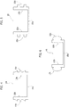
Figure 1 is a cross-section view of embodiments, -
Figure 2 exemplifies further possible features of embodiments, -
Figure 3 is a perspective view of one of the elements visible inFigure 2 , -
Figures 4 to 6 exemplify possible implementing modifications of embodiments, -
Figures 7 to 12 , on one hand, andFigures 13 to 18 , on the other hand, show various possible implementations of embodiments. - While possibly providing information related to the invention, embodiments as exemplified in
Figures 7 to 18 are not in accordance with the invention as claimed. - It will be appreciated that, for simplicity and clarity of illustration, the various Figures may not be drawn to the same scale.
- In the following description, various specific details are given to provide a thorough understanding of exemplary embodiments according to the present specification. The embodiments may be practiced without one or several specific details, or with other methods, components, materials, etc. In other instances, well-known structures, materials or operations are not shown or described in detail in order to avoid obscuring the various aspects of the embodiments.
- Reference throughout this specification to "one embodiment" or "an embodiment" means that a particular feature, structure, characteristic described in connection with the embodiment is included in at least one embodiment. Thus, the possible appearances of the phrases "in one embodiment" or "in an embodiment" in various places throughout this specification are not necessarily all referring exactly to the same embodiment. Furthermore, particular features, structures, or characteristics may be combined in any suitable manner in one or more embodiments.
- The headings provided herein are for convenience only, and therefore do not interpret the extent of protection or scope of the embodiments.
- In the Figures,
reference 100 generally denotes a lighting device adapted to include alight radiation generator 120 having a structure known in itself. Some possible exemplary implementations of said structure are discussed in the following with reference toFigures 7ff . - According to the invention, it is possible to apply, onto
generator 120, a profiledhousing 122 of a light-permeable material (e.g. a transparent silicone material) adapted to allow for the propagation of the light radiation emitted bygenerator 120 outwards fromdevice 100, e.g. at a rounded front surface ofhousing 122. - According to the invention,
housing 122 may perform a protection action against the penetration of external agents intodevice 100, e.g. with an IP degree protection. - Generally speaking (apart from what will be specified in further detail in the following), devices such as the device (or module) 100 exemplified in the foregoing are to be deemed as known in themselves, which makes it unnecessary to provide a more detailed description herein. This also applies to the possibility of implementing such a device as an element of indefinite length (shown in cross section in the Figures), optionally flexible and/or adapted to be cut to length according to the application and usage needs.
- One or more embodiments may deal with the problem of enabling mounting said device onto a mounting structure S.
- One or more embodiments may favour mounting
device 100 onto a wide range of mounting structures S. Said structures may include for instance a wall (e.g. a ceiling), an architectural element (e.g. a hand rail), a furnishing element of any nature, both in buildings and in moving structures such as vehicles and the like: this list is of course merely exemplary, and does not limit the embodiments. - According to the invention, the mounting of
device 100 takes place via afixation element 10. - In one or more embodiments,
element 10 may include a sort of profiled track adapted to be coupled to structure S, and having at least one formation for coupling withdevice 100. - In one or more embodiments as exemplified in
Figures 1 to 6 ,element 10 may include a channel-shaped track, including a central orcore wall 10a andside walls 10a extending sidewise ofcentral wall 10a. - In one or more embodiments, each
side wall 10b is adapted to form a rib-like protrusion, which may be inserted in a correspondinglongitudinal groove 100b provided indevice 100. - According to the invention, the groove (s) 100b (which may be provided in the same number as the rib-
like protrusions 10b in element 10) are located at the back portion (lower portion inFigures 1 and 2 ) of the housing ofdevice 100. - According to the invention, the groove (s) or slot(s) 100b are provided in a part of device 100 (e.g. the housing or profile 122) adapted to include a compliant material (e.g. a silicone material).
- In one or more embodiments, the rib(s) 10b may therefore penetrate the groove(s) 100b and may be retained therein, thanks to the deformability of the walls of the groove(s) 100b.
- In one or more embodiments, the rib(s) 10b may include
sculpturing 10c adapted to originate a firmer retention, e.g. thanks to a locking mechanism. - For example
Figures 1, 2 and4 exemplify a tooth-like sculpturing 10c, e.g. with a sawtooth profile adapted to implement a hooking coupling with the walls of the groove(s) 100b. - In one or more embodiments, the sculpturing features 10c may be present in different numbers and with different profiles, as shown - by way of example only - in
Figure 5 , which shows sculpturing features 10c arranged in pairs on each side wall 10d, and having a square/rectangular cross section, or inFigure 6 , showing sculpturing features 10c which extend (as a single sculpturing feature on eachside wall 10b) with a rounded, e.g. lobe-shaped, cross-section profile. - It will be appreciated, moreover, that in one or more embodiments:
-
sculpturing 10c may be provided not on the outer surface ofside walls 10b, but rather on the inner surface thereof, or both on the outer and on the inner surface, - in an embodiment not claimed, the coupling arrangement shown herein between
device 100 andelement 10 may be reversed, withdevice 100 having one or more protruding formations adapted to penetrate one or more longitudinal grooves ofelement 10. - One or more embodiments implementing the latter solution are exemplified in
Figures 7ff . -
Figures 7 to 11 refer to adevice 100 wherein the protection against the penetration of external agents is achieved through the use of a channel-shaped housing, whileFigures 13 to 17 refer to an equally protecteddevice 100 wherein the protection may be achieved during the forming (moulding) step ofdevice 100. - Moreover, said Figures exemplify possible implementation details of the light radiation generator which is generally denoted as 120 in
Figure 1 . - For example, in one or more embodiments as exemplified in
Figures 7ff ,generator 120 may include electrically powered light radiation sources, such as one or more LED sources.References Figures 7ff respectively denote the LED source (e.g. emitting in the blue range, with phosphor conversion into visible light) and the associated package. - In the same Figures,
reference 7 denotes a substrate (substantially similar to a Printed Circuit Board, PCB) for mounting source(s) 1, 2. -
Reference 8 denotes an insert (or spacer), optionally of a thermally conductive material, which in one or more embodiments may be interposed betweensubstrate 7 and the bottom wall of a channel-shapedhousing 9. - In one or more embodiments, as exemplified in
Figures 7 to 11 ,housing 9 is adapted to host thesubstrate 7, whereon source(s) 1, 2 are arranged, the channel-like shape ofhousing 9 being adapted to be filled with a potting mass. - In one or more embodiments, the potting mass may include a
material 5, e.g. a white or reflective, generally light-impermeable material, adapted e.g. to mask from observation from the outside ofdevice 100 electrical/electronic components and devices which may be mounted on the front surface ofsubstrate 7, as well as a further light-permeable material 3 (e.g. a transparent or diffusive material) which allows the light radiation produced bysource 1 to propagate outwards fromdevice 100. - In one or
more embodiments substrate 7, insert 8 (if present),housing 9 andmasses device 100 is generally flexible. -
Figures 7 to 11 exemplify various implementation solutions for one ormore ribs 91, adapted to protrude from the central wall of housing 9 (in the direction away from the front side ofdevice 9, from which the light radiation is diffused), so as to be inserted into one or more corresponding slots orgrooves fixation element 10. - For example, in one or more embodiments, the presence may be envisaged of one or
more ribs 91 having (transversally of the extension direction of device 100) a width increasing in the distal direction, away from the body ofdevice 100, so as to originate a dove-tail joint with one or morecorresponding cavities fixation element 10. - Specifically,
Figure 11 (and, in a complementary fashion,Figure 12 ) exemplify the possibility, in one or more embodiments, of envisaging the presence of a plurality ofribs 91 of this kind, each being adapted to engage a corresponding slot/groove fixation element 10. -
Figures 7 to 10 exemplify various features which may be present in one (or each) of saidribs 91. - For example:
-
Figure 8 exemplifies the possibility for the distal edges ofrib 91 to haveedge portions 92 protruding from the rounded profile, -
Figure 9 exemplifies the possible presence of acentral carving 93, adapted to favour the transversal shrinking ofrib 91, -
Figure 10 exemplifies the possible presence of chamferings or bevels 94 at the distal edges ofrib 91 and, at the same time, the possible presence ofedge portions 92 which are recessed into, and not protruding from, the rounded profile. - Similar or complementary features may also be present in the fixation element, as exemplified by the rounded/chamfered edges denoted as 104 in
Figure 12 and inFigure 18 . - In this respect it will be appreciated that, in one or more embodiments, the implementation features or details exemplified in each of the Figures annexed to the present description are adapted to be applied - individually or in mutual combination - to embodiments exemplified in any of the other Figures.
- This aspect is shown for example in
Figures 13 to 18 , wherein one or more features of rib(s) 91 exemplified with reference toFigures 7 to 12 are applied to adevice 100 having a protection obtained by moulding (Moulded Flex Protect), whereinsubstrate 7 hosting the light radiation source(s) 1, 2 is sealed against the penetration of external agents, by being moulded between: - a
first housing portion 6, which faces the back surface ofsubstrate 7 accommodated therein (from whichrib 91 may extend), and - a
second portion 4, which completes the sealing action against the penetration of external agents. - In one or more embodiments, the
first portion 6 may include a white or translucent, e.g. light-impermeable, material, whileportion 4 may include transparent or diffusive material, i.e. a light-permeable material, enabling the propagation towards the outside ofdevice 100 of the light radiation generated by source(s) 1, 2. - One or more embodiments may therefore envisage at least one protruding formation (rib) in one of
device 100 andfixation element 10, and at least one corresponding slot or groove e.g. in the other element. - According to the invention, as exemplified in
Figures 1 and 2 , the at least one protruding formation (rib) is provided (see e.g. 10b) in thefixation element 10, with one or more corresponding grooves (see e.g. 100b) provided indevice 100. - Once again by way of example, in one or more embodiments not claimed, as exemplified in
Figures 7ff the at least one protruding formation (rib) is provided (see e.g. 91) indevice 100, with one or more corresponding grooves (see e.g. 101, 102) provided in thefixation element 10. - In one or more embodiments as exemplified in
Figures 7ff , the coupling between such complementary portions (protruding formation(s) and groove(s)) may be implemented by a dove-tail joint. - In one or more embodiments it is possible to take advantage of the flexibility of the materials denoted as 3, 5, 9 as well as 4 and 6, both for the separation from a mould (see e.g. the embodiments exemplified in
Figures 13 to 17 ) and for the mounting (and removal), which may optionally be performed repeatedly, ofdevice 100 to and from thefixation element 10. - In one or more embodiments, the presence of rounded edges (as exemplified in
Figure 6 or as denoted as 92 in Figures such asFigure 9 orFigure 15 ) may simplify such mounting and removing operations. - The possible presence of a central slot or groove, such as the one denoted as 93 in Figures such as
Figures 9 and13 , may further simplify said mounting operations, by favouring the transversal shrinking ofrib 91. - The mounting/removal operation may also be simplified by the presence of chamferings or bevels, such as the ones denoted as 94 in
Figure 10 or inFigure 16 . - One or more embodiments may enable a simple mounting of
device 100 ontoelement 10 by a simple snap-on operation, optionally with the application of low side forces. - The removal operation of
device 100 fromfixation element 10 may take place, in one or more embodiments, simply through a pulling action exerted ontodevice 100 in a direction away fromfixation element 10. - One or more embodiments may enable an accurate positioning of
fixation element 10, which may be advantageous for signage applications, the possibility being given for example of initially defining the position offixation element 10 with accuracy, without involving thelighting device 100 in the operation. - In one or more embodiments, the complementary formations (rib(s) 10b, 91 and corresponding
cavities housing - In one or more embodiments, the sizes and shapes of said complementary formations may depend on the forming process thereof, e.g. with different cutting methods; for example, in the case of an extrusion process, the cavities may be larger than those implemented via laser cutting.
- In one or more embodiments, the retention force which may be achieved thanks to the coupling of said complementary features may be proportional to the size thereof, e.g. to the size of the cavity.
- For example, a small-sized cavity may exert a higher retention force than a large-sized cavity. On the other hand, the choice of a large-sized cavity may simplify the mounting and installation process.
- In one or more embodiments, the choice of a given shape of the complementary features may depend e.g. on the desired properties as regards the force needed for installing
device 100 ontofixation element 10, and/or on the desired retention force. Generally speaking, it may be assumed that, the higher the force needed during installation, the higher the retention force achieved. - As regards the mounting procedure of
fixation element 10, it may be stated that for example a generally rigid element 10 (e.g. a track of a light metal material) may be preferable for linear applications, the choice of a thermally conductive material being also useful for cooling, i.e. for dissipating the heat produced by the light radiation source(s) in operation. - The choice of a
flexible element 10, which may again include a metal material, may be useful in nonlinear applications, wherein a certain adaptability ofdevice 100 to the mounting structure is sought after. - It will be appreciated, moreover, that one or more embodiments are adapted to be employed in conjunction both with
modules 100 of a certain length and with modules having reduced length. - Once again it is to be noted that, in one or more embodiments, the implementation features or details exemplified in each of the Figures annexed to the present specification are adapted to be applied - individually or in mutual combination - to embodiments exemplified in any other Figure.
- One or more embodiments may be implemented as:
- a lighting
system including device 100 andelement 10; -
device 100 andelement 10, as components of said system, which are optionally provided separately and are subsequently assembled into the system; - a corresponding kit including, e.g. in a single package,
device 100 andelement 10, and - a method of employing the system.
- Without prejudice to the basic principles, the implementation details and the embodiments may vary, even appreciably, with respect to what has been described herein by way of non-limiting example only, without departing from the extent of protection.
- The extent of protection is determined by the annexed claims.
Claims (12)
- A lighting system, including:- an elongated lighting device (100) including a front light emission surface (122) and a back surface opposite said front surface, wherein the lighting device (100) includes a protected device including a flexible sealing encapsulation (122),- a fixation element (10) coupleable to a mounting structure (S),wherein the lighting device (100) and the fixation element (10) include complementary formations (10b, 100b) mutually engageable in a form-coupling relationship, and wherein: said complementary formations include at least one groove (100b) provided in said flexible sealing encapsulation (122) at said back surface of the lighting device (100) and at least one rib-like protrusion (10b) in the fixation element (10), characterised in that the flexible sealing encapsulation (122) consists of light-permeable material.
- The lighting system of claim 1, wherein said complementary formations include sculpturing (10c) on at least one (10b) of said complementary formations.
- The lighting system of claim 2, wherein said sculpturing (10c) includes tooth-like formations.
- The lighting system of any of the previous claims, wherein said complementary formations include rounded regions (10c).
- The lighting system of any of the previous claims, wherein said complementary formations include material (100b) facilitating deformation of the complementary formations during coupling.
- The lighting system of claim 5, wherein said complementary formations include material (100b) facilitating deformation of the complementary formations during coupling via elastic coupling.
- The lighting system of any of the previous claims, wherein the complementary formations include a plurality of pairs (10b, 100b) of mutually engageable complementary formations.
- The lighting system of any of the previous claims, wherein said lighting device (100) includes at least one solid-state light radiation source (1, 2).
- The lighting system of claim 8, wherein said lighting device (100) includes at least one LED source (1, 2).
- A method of providing a lighting device, wherein the method includes:- providing an elongated lighting device (100) including a front light emission surface (122) and a back surface opposite said front surface, and a fixation element (10) coupleable to a mounting structure (S), wherein the lighting device (100) includes a protected device including a flexible sealing encapsulation (122),- providing the lighting device (100) and the fixation element (10) with complementary formations (10b, 100b) mutually engageable in a form-coupling relationship, wherein:
the flexible sealing encapsulation (122) consists of light-permeable material and said complementary formations include at least one groove (100b) provided in said flexible sealing encapsulation (122) at said back surface of the lighting device (100) and at least one rib-like protrusion (10b) in the fixation element (10),
and- coupling the lighting device (100) and the fixation element (10) by bringing said complementary formations (10b, 100b; 91, 101, 102) into a form-coupling relationship. - The method of claim 10, including coupling the fixation element (10) to a mounting structure (S).
- The method of claim 11, including coupling the fixation element (10) to a mounting structure (S) prior to coupling the lighting device (100) and the fixation element (10).
Applications Claiming Priority (1)
| Application Number | Priority Date | Filing Date | Title |
|---|---|---|---|
| IT201700003095 | 2017-01-12 |
Publications (3)
| Publication Number | Publication Date |
|---|---|
| EP3348897A1 EP3348897A1 (en) | 2018-07-18 |
| EP3348897B1 true EP3348897B1 (en) | 2020-07-08 |
| EP3348897B8 EP3348897B8 (en) | 2020-08-19 |
Family
ID=58671838
Family Applications (1)
| Application Number | Title | Priority Date | Filing Date |
|---|---|---|---|
| EP18151042.1A Active EP3348897B8 (en) | 2017-01-12 | 2018-01-10 | A lighting system and corresponding method |
Country Status (1)
| Country | Link |
|---|---|
| EP (1) | EP3348897B8 (en) |
Families Citing this family (3)
| Publication number | Priority date | Publication date | Assignee | Title |
|---|---|---|---|---|
| EP3904753B1 (en) * | 2020-04-30 | 2025-11-12 | Lumileds LLC | Bracket, light module including the same and method for manufacturing the same |
| FI20206146A1 (en) * | 2020-11-12 | 2022-05-13 | Teknoware Oy | LED strips and process for the production of LED strips |
| WO2026021853A1 (en) | 2024-07-22 | 2026-01-29 | Signify Holding B.V. | Luminaire kit |
Family Cites Families (6)
| Publication number | Priority date | Publication date | Assignee | Title |
|---|---|---|---|---|
| US5337225A (en) * | 1993-01-06 | 1994-08-09 | The Standard Products Company | Lighting strip system |
| US5934792A (en) * | 1997-02-24 | 1999-08-10 | Itc, Inc. | Flexible lighting system |
| CN1279755A (en) * | 1997-07-28 | 2001-01-10 | 拉米尔德斯照明设备美国有限公司 | strip lighting |
| WO2008134424A2 (en) * | 2007-04-24 | 2008-11-06 | Lumination Llc | Led perimeter lighting system |
| US8083370B2 (en) * | 2008-05-09 | 2011-12-27 | The Sloan Company, Inc. | Low profile extrusion |
| US20140313722A1 (en) * | 2013-04-17 | 2014-10-23 | Raw Thrills, Inc. | Flexible Decorative Lighted Strip, Cabinet Including Same, and Installation Method |
-
2018
- 2018-01-10 EP EP18151042.1A patent/EP3348897B8/en active Active
Non-Patent Citations (1)
| Title |
|---|
| None * |
Also Published As
| Publication number | Publication date |
|---|---|
| EP3348897B8 (en) | 2020-08-19 |
| EP3348897A1 (en) | 2018-07-18 |
Similar Documents
| Publication | Publication Date | Title |
|---|---|---|
| EP1891671B1 (en) | Light-emitting module | |
| EP2430357B1 (en) | Low profile extrusion | |
| CN101681804B (en) | Sealed lighting units | |
| KR101666707B1 (en) | Explosion-proof LED module | |
| US9518716B1 (en) | Linear wide area lighting system | |
| EP3348897A1 (en) | A lighting system, corresponding components, kit and method | |
| WO2011126563A1 (en) | Low profile extrusion | |
| DE102008013454B4 (en) | LED assembly for lighting | |
| US20150330584A1 (en) | Lighting device and corresponding mounting housing, kit and method | |
| EP3387325A1 (en) | A casing for lighting devices, corresponding device and method | |
| US9361813B1 (en) | Recessed luminaire installation with minimal disturbance of ceiling aesthetics | |
| US20180180271A1 (en) | Lighting device and corresponding method | |
| EP3254020B1 (en) | Led module and method of sealing | |
| CN104685746B (en) | sleeve seal | |
| KR101609316B1 (en) | LED Lamp for Outdoor | |
| KR100933890B1 (en) | Manufacturing method of LED lighting | |
| EP2565532B1 (en) | Illumination device | |
| CN108506892A (en) | Lamp cover and lamp | |
| JP6708413B2 (en) | Lighting device and installation method of lighting device | |
| KR200379827Y1 (en) | An advertising lighting apparatus for signboard | |
| CN111051766A (en) | Tool-free lighting fixing device | |
| ES2555509T3 (en) | Improvements in and relating to glazing clamps for auxiliary elements in glazing units | |
| WO2014152927A1 (en) | Trim cap illuminated channel letter lighting system and letter construction system | |
| KR101407712B1 (en) | LED lighting panel for crucifix | |
| EP4720562A1 (en) | Lighting device for use with led strips |
Legal Events
| Date | Code | Title | Description |
|---|---|---|---|
| PUAI | Public reference made under article 153(3) epc to a published international application that has entered the european phase |
Free format text: ORIGINAL CODE: 0009012 |
|
| STAA | Information on the status of an ep patent application or granted ep patent |
Free format text: STATUS: THE APPLICATION HAS BEEN PUBLISHED |
|
| AK | Designated contracting states |
Kind code of ref document: A1 Designated state(s): AL AT BE BG CH CY CZ DE DK EE ES FI FR GB GR HR HU IE IS IT LI LT LU LV MC MK MT NL NO PL PT RO RS SE SI SK SM TR |
|
| AX | Request for extension of the european patent |
Extension state: BA ME |
|
| STAA | Information on the status of an ep patent application or granted ep patent |
Free format text: STATUS: REQUEST FOR EXAMINATION WAS MADE |
|
| 17P | Request for examination filed |
Effective date: 20181128 |
|
| RBV | Designated contracting states (corrected) |
Designated state(s): AL AT BE BG CH CY CZ DE DK EE ES FI FR GB GR HR HU IE IS IT LI LT LU LV MC MK MT NL NO PL PT RO RS SE SI SK SM TR |
|
| STAA | Information on the status of an ep patent application or granted ep patent |
Free format text: STATUS: EXAMINATION IS IN PROGRESS |
|
| 17Q | First examination report despatched |
Effective date: 20190916 |
|
| RIC1 | Information provided on ipc code assigned before grant |
Ipc: F21V 21/02 20060101ALI20200116BHEP Ipc: F21S 4/22 20160101AFI20200116BHEP Ipc: F21Y 115/10 20160101ALN20200116BHEP |
|
| GRAP | Despatch of communication of intention to grant a patent |
Free format text: ORIGINAL CODE: EPIDOSNIGR1 |
|
| STAA | Information on the status of an ep patent application or granted ep patent |
Free format text: STATUS: GRANT OF PATENT IS INTENDED |
|
| RIC1 | Information provided on ipc code assigned before grant |
Ipc: F21V 21/02 20060101ALI20200212BHEP Ipc: F21Y 115/10 20160101ALN20200212BHEP Ipc: F21S 4/22 20160101AFI20200212BHEP |
|
| INTG | Intention to grant announced |
Effective date: 20200224 |
|
| GRAS | Grant fee paid |
Free format text: ORIGINAL CODE: EPIDOSNIGR3 |
|
| GRAA | (expected) grant |
Free format text: ORIGINAL CODE: 0009210 |
|
| STAA | Information on the status of an ep patent application or granted ep patent |
Free format text: STATUS: THE PATENT HAS BEEN GRANTED |
|
| GRAT | Correction requested after decision to grant or after decision to maintain patent in amended form |
Free format text: ORIGINAL CODE: EPIDOSNCDEC |
|
| AK | Designated contracting states |
Kind code of ref document: B1 Designated state(s): AL AT BE BG CH CY CZ DE DK EE ES FI FR GB GR HR HU IE IS IT LI LT LU LV MC MK MT NL NO PL PT RO RS SE SI SK SM TR |
|
| REG | Reference to a national code |
Ref country code: AT Ref legal event code: REF Ref document number: 1288843 Country of ref document: AT Kind code of ref document: T Effective date: 20200715 Ref country code: CH Ref legal event code: EP |
|
| RAP2 | Party data changed (patent owner data changed or rights of a patent transferred) |
Owner name: OSRAM GMBH Owner name: OSRAM S.P.A. - SOCIETA' RIUNITE OSRAM EDISON CLERICI |
|
| REG | Reference to a national code |
Ref country code: DE Ref legal event code: R096 Ref document number: 602018005752 Country of ref document: DE |
|
| REG | Reference to a national code |
Ref country code: CH Ref legal event code: PK Free format text: BERICHTIGUNG B8 |
|
| REG | Reference to a national code |
Ref country code: IE Ref legal event code: FG4D |
|
| RAP2 | Party data changed (patent owner data changed or rights of a patent transferred) |
Owner name: OSRAM GMBH Owner name: OSRAM S.P.A. - SOCIETA' RIUNITE OSRAM EDISON CLERICI |
|
| REG | Reference to a national code |
Ref country code: LT Ref legal event code: MG4D |
|
| REG | Reference to a national code |
Ref country code: AT Ref legal event code: MK05 Ref document number: 1288843 Country of ref document: AT Kind code of ref document: T Effective date: 20200708 |
|
| REG | Reference to a national code |
Ref country code: NL Ref legal event code: MP Effective date: 20200708 |
|
| PG25 | Lapsed in a contracting state [announced via postgrant information from national office to epo] |
Ref country code: HR Free format text: LAPSE BECAUSE OF FAILURE TO SUBMIT A TRANSLATION OF THE DESCRIPTION OR TO PAY THE FEE WITHIN THE PRESCRIBED TIME-LIMIT Effective date: 20200708 Ref country code: ES Free format text: LAPSE BECAUSE OF FAILURE TO SUBMIT A TRANSLATION OF THE DESCRIPTION OR TO PAY THE FEE WITHIN THE PRESCRIBED TIME-LIMIT Effective date: 20200708 Ref country code: SE Free format text: LAPSE BECAUSE OF FAILURE TO SUBMIT A TRANSLATION OF THE DESCRIPTION OR TO PAY THE FEE WITHIN THE PRESCRIBED TIME-LIMIT Effective date: 20200708 Ref country code: BG Free format text: LAPSE BECAUSE OF FAILURE TO SUBMIT A TRANSLATION OF THE DESCRIPTION OR TO PAY THE FEE WITHIN THE PRESCRIBED TIME-LIMIT Effective date: 20201008 Ref country code: GR Free format text: LAPSE BECAUSE OF FAILURE TO SUBMIT A TRANSLATION OF THE DESCRIPTION OR TO PAY THE FEE WITHIN THE PRESCRIBED TIME-LIMIT Effective date: 20201009 Ref country code: NO Free format text: LAPSE BECAUSE OF FAILURE TO SUBMIT A TRANSLATION OF THE DESCRIPTION OR TO PAY THE FEE WITHIN THE PRESCRIBED TIME-LIMIT Effective date: 20201008 Ref country code: AT Free format text: LAPSE BECAUSE OF FAILURE TO SUBMIT A TRANSLATION OF THE DESCRIPTION OR TO PAY THE FEE WITHIN THE PRESCRIBED TIME-LIMIT Effective date: 20200708 Ref country code: PT Free format text: LAPSE BECAUSE OF FAILURE TO SUBMIT A TRANSLATION OF THE DESCRIPTION OR TO PAY THE FEE WITHIN THE PRESCRIBED TIME-LIMIT Effective date: 20201109 Ref country code: LT Free format text: LAPSE BECAUSE OF FAILURE TO SUBMIT A TRANSLATION OF THE DESCRIPTION OR TO PAY THE FEE WITHIN THE PRESCRIBED TIME-LIMIT Effective date: 20200708 Ref country code: FI Free format text: LAPSE BECAUSE OF FAILURE TO SUBMIT A TRANSLATION OF THE DESCRIPTION OR TO PAY THE FEE WITHIN THE PRESCRIBED TIME-LIMIT Effective date: 20200708 |
|
| PG25 | Lapsed in a contracting state [announced via postgrant information from national office to epo] |
Ref country code: IS Free format text: LAPSE BECAUSE OF FAILURE TO SUBMIT A TRANSLATION OF THE DESCRIPTION OR TO PAY THE FEE WITHIN THE PRESCRIBED TIME-LIMIT Effective date: 20201108 Ref country code: LV Free format text: LAPSE BECAUSE OF FAILURE TO SUBMIT A TRANSLATION OF THE DESCRIPTION OR TO PAY THE FEE WITHIN THE PRESCRIBED TIME-LIMIT Effective date: 20200708 Ref country code: RS Free format text: LAPSE BECAUSE OF FAILURE TO SUBMIT A TRANSLATION OF THE DESCRIPTION OR TO PAY THE FEE WITHIN THE PRESCRIBED TIME-LIMIT Effective date: 20200708 Ref country code: PL Free format text: LAPSE BECAUSE OF FAILURE TO SUBMIT A TRANSLATION OF THE DESCRIPTION OR TO PAY THE FEE WITHIN THE PRESCRIBED TIME-LIMIT Effective date: 20200708 |
|
| PG25 | Lapsed in a contracting state [announced via postgrant information from national office to epo] |
Ref country code: NL Free format text: LAPSE BECAUSE OF FAILURE TO SUBMIT A TRANSLATION OF THE DESCRIPTION OR TO PAY THE FEE WITHIN THE PRESCRIBED TIME-LIMIT Effective date: 20200708 |
|
| REG | Reference to a national code |
Ref country code: DE Ref legal event code: R097 Ref document number: 602018005752 Country of ref document: DE |
|
| PG25 | Lapsed in a contracting state [announced via postgrant information from national office to epo] |
Ref country code: CZ Free format text: LAPSE BECAUSE OF FAILURE TO SUBMIT A TRANSLATION OF THE DESCRIPTION OR TO PAY THE FEE WITHIN THE PRESCRIBED TIME-LIMIT Effective date: 20200708 Ref country code: DK Free format text: LAPSE BECAUSE OF FAILURE TO SUBMIT A TRANSLATION OF THE DESCRIPTION OR TO PAY THE FEE WITHIN THE PRESCRIBED TIME-LIMIT Effective date: 20200708 Ref country code: RO Free format text: LAPSE BECAUSE OF FAILURE TO SUBMIT A TRANSLATION OF THE DESCRIPTION OR TO PAY THE FEE WITHIN THE PRESCRIBED TIME-LIMIT Effective date: 20200708 Ref country code: EE Free format text: LAPSE BECAUSE OF FAILURE TO SUBMIT A TRANSLATION OF THE DESCRIPTION OR TO PAY THE FEE WITHIN THE PRESCRIBED TIME-LIMIT Effective date: 20200708 Ref country code: SM Free format text: LAPSE BECAUSE OF FAILURE TO SUBMIT A TRANSLATION OF THE DESCRIPTION OR TO PAY THE FEE WITHIN THE PRESCRIBED TIME-LIMIT Effective date: 20200708 Ref country code: IT Free format text: LAPSE BECAUSE OF FAILURE TO SUBMIT A TRANSLATION OF THE DESCRIPTION OR TO PAY THE FEE WITHIN THE PRESCRIBED TIME-LIMIT Effective date: 20200708 |
|
| PLBE | No opposition filed within time limit |
Free format text: ORIGINAL CODE: 0009261 |
|
| STAA | Information on the status of an ep patent application or granted ep patent |
Free format text: STATUS: NO OPPOSITION FILED WITHIN TIME LIMIT |
|
| PG25 | Lapsed in a contracting state [announced via postgrant information from national office to epo] |
Ref country code: AL Free format text: LAPSE BECAUSE OF FAILURE TO SUBMIT A TRANSLATION OF THE DESCRIPTION OR TO PAY THE FEE WITHIN THE PRESCRIBED TIME-LIMIT Effective date: 20200708 |
|
| 26N | No opposition filed |
Effective date: 20210409 |
|
| PG25 | Lapsed in a contracting state [announced via postgrant information from national office to epo] |
Ref country code: SK Free format text: LAPSE BECAUSE OF FAILURE TO SUBMIT A TRANSLATION OF THE DESCRIPTION OR TO PAY THE FEE WITHIN THE PRESCRIBED TIME-LIMIT Effective date: 20200708 |
|
| PG25 | Lapsed in a contracting state [announced via postgrant information from national office to epo] |
Ref country code: SI Free format text: LAPSE BECAUSE OF FAILURE TO SUBMIT A TRANSLATION OF THE DESCRIPTION OR TO PAY THE FEE WITHIN THE PRESCRIBED TIME-LIMIT Effective date: 20200708 Ref country code: MC Free format text: LAPSE BECAUSE OF FAILURE TO SUBMIT A TRANSLATION OF THE DESCRIPTION OR TO PAY THE FEE WITHIN THE PRESCRIBED TIME-LIMIT Effective date: 20200708 |
|
| REG | Reference to a national code |
Ref country code: CH Ref legal event code: PL |
|
| PG25 | Lapsed in a contracting state [announced via postgrant information from national office to epo] |
Ref country code: LU Free format text: LAPSE BECAUSE OF NON-PAYMENT OF DUE FEES Effective date: 20210110 |
|
| REG | Reference to a national code |
Ref country code: BE Ref legal event code: MM Effective date: 20210131 |
|
| PG25 | Lapsed in a contracting state [announced via postgrant information from national office to epo] |
Ref country code: FR Free format text: LAPSE BECAUSE OF NON-PAYMENT OF DUE FEES Effective date: 20210131 |
|
| PG25 | Lapsed in a contracting state [announced via postgrant information from national office to epo] |
Ref country code: LI Free format text: LAPSE BECAUSE OF NON-PAYMENT OF DUE FEES Effective date: 20210131 Ref country code: CH Free format text: LAPSE BECAUSE OF NON-PAYMENT OF DUE FEES Effective date: 20210131 |
|
| PG25 | Lapsed in a contracting state [announced via postgrant information from national office to epo] |
Ref country code: IE Free format text: LAPSE BECAUSE OF NON-PAYMENT OF DUE FEES Effective date: 20210110 |
|
| PG25 | Lapsed in a contracting state [announced via postgrant information from national office to epo] |
Ref country code: BE Free format text: LAPSE BECAUSE OF NON-PAYMENT OF DUE FEES Effective date: 20210131 |
|
| GBPC | Gb: european patent ceased through non-payment of renewal fee |
Effective date: 20220110 |
|
| PG25 | Lapsed in a contracting state [announced via postgrant information from national office to epo] |
Ref country code: GB Free format text: LAPSE BECAUSE OF NON-PAYMENT OF DUE FEES Effective date: 20220110 |
|
| REG | Reference to a national code |
Ref country code: DE Ref legal event code: R081 Ref document number: 602018005752 Country of ref document: DE Owner name: OPTOTRONIC GMBH, DE Free format text: FORMER OWNER: OSRAM GMBH, 80807 MUENCHEN, DE Ref country code: DE Ref legal event code: R081 Ref document number: 602018005752 Country of ref document: DE Owner name: INVENTRONICS GMBH, DE Free format text: FORMER OWNER: OSRAM GMBH, 80807 MUENCHEN, DE |
|
| PG25 | Lapsed in a contracting state [announced via postgrant information from national office to epo] |
Ref country code: CY Free format text: LAPSE BECAUSE OF FAILURE TO SUBMIT A TRANSLATION OF THE DESCRIPTION OR TO PAY THE FEE WITHIN THE PRESCRIBED TIME-LIMIT Effective date: 20200708 |
|
| PG25 | Lapsed in a contracting state [announced via postgrant information from national office to epo] |
Ref country code: HU Free format text: LAPSE BECAUSE OF FAILURE TO SUBMIT A TRANSLATION OF THE DESCRIPTION OR TO PAY THE FEE WITHIN THE PRESCRIBED TIME-LIMIT; INVALID AB INITIO Effective date: 20180110 |
|
| PG25 | Lapsed in a contracting state [announced via postgrant information from national office to epo] |
Ref country code: MK Free format text: LAPSE BECAUSE OF FAILURE TO SUBMIT A TRANSLATION OF THE DESCRIPTION OR TO PAY THE FEE WITHIN THE PRESCRIBED TIME-LIMIT Effective date: 20200708 |
|
| REG | Reference to a national code |
Ref country code: DE Ref legal event code: R081 Ref document number: 602018005752 Country of ref document: DE Owner name: INVENTRONICS GMBH, DE Free format text: FORMER OWNER: OPTOTRONIC GMBH, 85748 GARCHING, DE |
|
| PG25 | Lapsed in a contracting state [announced via postgrant information from national office to epo] |
Ref country code: MT Free format text: LAPSE BECAUSE OF FAILURE TO SUBMIT A TRANSLATION OF THE DESCRIPTION OR TO PAY THE FEE WITHIN THE PRESCRIBED TIME-LIMIT Effective date: 20200708 |
|
| PG25 | Lapsed in a contracting state [announced via postgrant information from national office to epo] |
Ref country code: TR Free format text: LAPSE BECAUSE OF FAILURE TO SUBMIT A TRANSLATION OF THE DESCRIPTION OR TO PAY THE FEE WITHIN THE PRESCRIBED TIME-LIMIT Effective date: 20200708 |
|
| PGFP | Annual fee paid to national office [announced via postgrant information from national office to epo] |
Ref country code: DE Payment date: 20260120 Year of fee payment: 9 |