EP3348850A1 - Bearing ring manufacturing method - Google Patents
Bearing ring manufacturing method Download PDFInfo
- Publication number
- EP3348850A1 EP3348850A1 EP16844167.3A EP16844167A EP3348850A1 EP 3348850 A1 EP3348850 A1 EP 3348850A1 EP 16844167 A EP16844167 A EP 16844167A EP 3348850 A1 EP3348850 A1 EP 3348850A1
- Authority
- EP
- European Patent Office
- Prior art keywords
- ring
- rolling bearing
- bearing ring
- die
- form member
- Prior art date
- Legal status (The legal status is an assumption and is not a legal conclusion. Google has not performed a legal analysis and makes no representation as to the accuracy of the status listed.)
- Withdrawn
Links
- 238000004519 manufacturing process Methods 0.000 title claims abstract description 69
- 239000000463 material Substances 0.000 claims abstract description 117
- 238000005096 rolling process Methods 0.000 claims abstract description 94
- 229910000831 Steel Inorganic materials 0.000 claims abstract description 55
- 239000010959 steel Substances 0.000 claims abstract description 55
- 238000010791 quenching Methods 0.000 claims abstract description 35
- 230000000171 quenching effect Effects 0.000 claims abstract description 33
- 238000003825 pressing Methods 0.000 claims abstract description 29
- 238000004080 punching Methods 0.000 claims abstract description 26
- 230000009466 transformation Effects 0.000 claims abstract description 9
- OKTJSMMVPCPJKN-UHFFFAOYSA-N Carbon Chemical compound [C] OKTJSMMVPCPJKN-UHFFFAOYSA-N 0.000 claims description 6
- 229910052799 carbon Inorganic materials 0.000 claims description 6
- 238000009740 moulding (composite fabrication) Methods 0.000 description 70
- 238000010438 heat treatment Methods 0.000 description 44
- 238000010586 diagram Methods 0.000 description 29
- 238000000034 method Methods 0.000 description 23
- 230000000052 comparative effect Effects 0.000 description 13
- 238000001816 cooling Methods 0.000 description 8
- 230000020169 heat generation Effects 0.000 description 8
- 238000010276 construction Methods 0.000 description 6
- 230000004048 modification Effects 0.000 description 6
- 238000012986 modification Methods 0.000 description 6
- 230000008569 process Effects 0.000 description 6
- 238000005496 tempering Methods 0.000 description 6
- 239000000498 cooling water Substances 0.000 description 5
- 230000000694 effects Effects 0.000 description 5
- 230000006698 induction Effects 0.000 description 4
- 229910000734 martensite Inorganic materials 0.000 description 4
- XLYOFNOQVPJJNP-UHFFFAOYSA-N water Substances O XLYOFNOQVPJJNP-UHFFFAOYSA-N 0.000 description 4
- 230000037303 wrinkles Effects 0.000 description 4
- 229910001566 austenite Inorganic materials 0.000 description 3
- 230000008859 change Effects 0.000 description 3
- 238000004804 winding Methods 0.000 description 3
- 229910001315 Tool steel Inorganic materials 0.000 description 2
- 238000005452 bending Methods 0.000 description 2
- 230000004907 flux Effects 0.000 description 2
- 238000004904 shortening Methods 0.000 description 2
- 229910000975 Carbon steel Inorganic materials 0.000 description 1
- 229910000639 Spring steel Inorganic materials 0.000 description 1
- 230000004913 activation Effects 0.000 description 1
- 229910045601 alloy Inorganic materials 0.000 description 1
- 239000000956 alloy Substances 0.000 description 1
- 239000010962 carbon steel Substances 0.000 description 1
- 238000006243 chemical reaction Methods 0.000 description 1
- 238000011156 evaluation Methods 0.000 description 1
- 230000001678 irradiating effect Effects 0.000 description 1
- 230000007246 mechanism Effects 0.000 description 1
- FXNGWBDIVIGISM-UHFFFAOYSA-N methylidynechromium Chemical group [Cr]#[C] FXNGWBDIVIGISM-UHFFFAOYSA-N 0.000 description 1
- 230000003287 optical effect Effects 0.000 description 1
- 238000002360 preparation method Methods 0.000 description 1
- 230000002040 relaxant effect Effects 0.000 description 1
- 239000011347 resin Substances 0.000 description 1
- 229920005989 resin Polymers 0.000 description 1
- 230000000717 retained effect Effects 0.000 description 1
- 102200003959 rs11556986 Human genes 0.000 description 1
- 102200081478 rs121908458 Human genes 0.000 description 1
- 102220005308 rs33960931 Human genes 0.000 description 1
- 102220259718 rs34120878 Human genes 0.000 description 1
- 102200082816 rs34868397 Human genes 0.000 description 1
- 238000010008 shearing Methods 0.000 description 1
- 239000010935 stainless steel Substances 0.000 description 1
- 229910001220 stainless steel Inorganic materials 0.000 description 1
- 229910000859 α-Fe Inorganic materials 0.000 description 1
Images






Classifications
-
- B—PERFORMING OPERATIONS; TRANSPORTING
- B21—MECHANICAL METAL-WORKING WITHOUT ESSENTIALLY REMOVING MATERIAL; PUNCHING METAL
- B21D—WORKING OR PROCESSING OF SHEET METAL OR METAL TUBES, RODS OR PROFILES WITHOUT ESSENTIALLY REMOVING MATERIAL; PUNCHING METAL
- B21D53/00—Making other particular articles
- B21D53/10—Making other particular articles parts of bearings; sleeves; valve seats or the like
-
- B—PERFORMING OPERATIONS; TRANSPORTING
- B21—MECHANICAL METAL-WORKING WITHOUT ESSENTIALLY REMOVING MATERIAL; PUNCHING METAL
- B21D—WORKING OR PROCESSING OF SHEET METAL OR METAL TUBES, RODS OR PROFILES WITHOUT ESSENTIALLY REMOVING MATERIAL; PUNCHING METAL
- B21D19/00—Flanging or other edge treatment, e.g. of tubes
- B21D19/08—Flanging or other edge treatment, e.g. of tubes by single or successive action of pressing tools, e.g. vice jaws
-
- B—PERFORMING OPERATIONS; TRANSPORTING
- B21—MECHANICAL METAL-WORKING WITHOUT ESSENTIALLY REMOVING MATERIAL; PUNCHING METAL
- B21D—WORKING OR PROCESSING OF SHEET METAL OR METAL TUBES, RODS OR PROFILES WITHOUT ESSENTIALLY REMOVING MATERIAL; PUNCHING METAL
- B21D22/00—Shaping without cutting, by stamping, spinning, or deep-drawing
- B21D22/02—Stamping using rigid devices or tools
- B21D22/022—Stamping using rigid devices or tools by heating the blank or stamping associated with heat treatment
-
- B—PERFORMING OPERATIONS; TRANSPORTING
- B21—MECHANICAL METAL-WORKING WITHOUT ESSENTIALLY REMOVING MATERIAL; PUNCHING METAL
- B21D—WORKING OR PROCESSING OF SHEET METAL OR METAL TUBES, RODS OR PROFILES WITHOUT ESSENTIALLY REMOVING MATERIAL; PUNCHING METAL
- B21D22/00—Shaping without cutting, by stamping, spinning, or deep-drawing
- B21D22/20—Deep-drawing
-
- B—PERFORMING OPERATIONS; TRANSPORTING
- B21—MECHANICAL METAL-WORKING WITHOUT ESSENTIALLY REMOVING MATERIAL; PUNCHING METAL
- B21D—WORKING OR PROCESSING OF SHEET METAL OR METAL TUBES, RODS OR PROFILES WITHOUT ESSENTIALLY REMOVING MATERIAL; PUNCHING METAL
- B21D24/00—Special deep-drawing arrangements in, or in connection with, presses
- B21D24/16—Additional equipment in association with the tools, e.g. for shearing, for trimming
-
- B—PERFORMING OPERATIONS; TRANSPORTING
- B21—MECHANICAL METAL-WORKING WITHOUT ESSENTIALLY REMOVING MATERIAL; PUNCHING METAL
- B21D—WORKING OR PROCESSING OF SHEET METAL OR METAL TUBES, RODS OR PROFILES WITHOUT ESSENTIALLY REMOVING MATERIAL; PUNCHING METAL
- B21D28/00—Shaping by press-cutting; Perforating
- B21D28/02—Punching blanks or articles with or without obtaining scrap; Notching
-
- B—PERFORMING OPERATIONS; TRANSPORTING
- B21—MECHANICAL METAL-WORKING WITHOUT ESSENTIALLY REMOVING MATERIAL; PUNCHING METAL
- B21D—WORKING OR PROCESSING OF SHEET METAL OR METAL TUBES, RODS OR PROFILES WITHOUT ESSENTIALLY REMOVING MATERIAL; PUNCHING METAL
- B21D28/00—Shaping by press-cutting; Perforating
- B21D28/02—Punching blanks or articles with or without obtaining scrap; Notching
- B21D28/14—Dies
-
- B—PERFORMING OPERATIONS; TRANSPORTING
- B21—MECHANICAL METAL-WORKING WITHOUT ESSENTIALLY REMOVING MATERIAL; PUNCHING METAL
- B21D—WORKING OR PROCESSING OF SHEET METAL OR METAL TUBES, RODS OR PROFILES WITHOUT ESSENTIALLY REMOVING MATERIAL; PUNCHING METAL
- B21D53/00—Making other particular articles
- B21D53/16—Making other particular articles rings, e.g. barrel hoops
-
- C—CHEMISTRY; METALLURGY
- C21—METALLURGY OF IRON
- C21D—MODIFYING THE PHYSICAL STRUCTURE OF FERROUS METALS; GENERAL DEVICES FOR HEAT TREATMENT OF FERROUS OR NON-FERROUS METALS OR ALLOYS; MAKING METAL MALLEABLE, e.g. BY DECARBURISATION OR TEMPERING
- C21D1/00—General methods or devices for heat treatment, e.g. annealing, hardening, quenching or tempering
- C21D1/18—Hardening; Quenching with or without subsequent tempering
-
- C—CHEMISTRY; METALLURGY
- C21—METALLURGY OF IRON
- C21D—MODIFYING THE PHYSICAL STRUCTURE OF FERROUS METALS; GENERAL DEVICES FOR HEAT TREATMENT OF FERROUS OR NON-FERROUS METALS OR ALLOYS; MAKING METAL MALLEABLE, e.g. BY DECARBURISATION OR TEMPERING
- C21D1/00—General methods or devices for heat treatment, e.g. annealing, hardening, quenching or tempering
- C21D1/34—Methods of heating
- C21D1/42—Induction heating
-
- C—CHEMISTRY; METALLURGY
- C21—METALLURGY OF IRON
- C21D—MODIFYING THE PHYSICAL STRUCTURE OF FERROUS METALS; GENERAL DEVICES FOR HEAT TREATMENT OF FERROUS OR NON-FERROUS METALS OR ALLOYS; MAKING METAL MALLEABLE, e.g. BY DECARBURISATION OR TEMPERING
- C21D9/00—Heat treatment, e.g. annealing, hardening, quenching or tempering, adapted for particular articles; Furnaces therefor
- C21D9/40—Heat treatment, e.g. annealing, hardening, quenching or tempering, adapted for particular articles; Furnaces therefor for rings; for bearing races
-
- F—MECHANICAL ENGINEERING; LIGHTING; HEATING; WEAPONS; BLASTING
- F16—ENGINEERING ELEMENTS AND UNITS; GENERAL MEASURES FOR PRODUCING AND MAINTAINING EFFECTIVE FUNCTIONING OF MACHINES OR INSTALLATIONS; THERMAL INSULATION IN GENERAL
- F16C—SHAFTS; FLEXIBLE SHAFTS; ELEMENTS OR CRANKSHAFT MECHANISMS; ROTARY BODIES OTHER THAN GEARING ELEMENTS; BEARINGS
- F16C19/00—Bearings with rolling contact, for exclusively rotary movement
- F16C19/22—Bearings with rolling contact, for exclusively rotary movement with bearing rollers essentially of the same size in one or more circular rows, e.g. needle bearings
- F16C19/30—Bearings with rolling contact, for exclusively rotary movement with bearing rollers essentially of the same size in one or more circular rows, e.g. needle bearings for axial load mainly
-
- F—MECHANICAL ENGINEERING; LIGHTING; HEATING; WEAPONS; BLASTING
- F16—ENGINEERING ELEMENTS AND UNITS; GENERAL MEASURES FOR PRODUCING AND MAINTAINING EFFECTIVE FUNCTIONING OF MACHINES OR INSTALLATIONS; THERMAL INSULATION IN GENERAL
- F16C—SHAFTS; FLEXIBLE SHAFTS; ELEMENTS OR CRANKSHAFT MECHANISMS; ROTARY BODIES OTHER THAN GEARING ELEMENTS; BEARINGS
- F16C33/00—Parts of bearings; Special methods for making bearings or parts thereof
- F16C33/30—Parts of ball or roller bearings
- F16C33/58—Raceways; Race rings
- F16C33/64—Special methods of manufacture
-
- B—PERFORMING OPERATIONS; TRANSPORTING
- B21—MECHANICAL METAL-WORKING WITHOUT ESSENTIALLY REMOVING MATERIAL; PUNCHING METAL
- B21D—WORKING OR PROCESSING OF SHEET METAL OR METAL TUBES, RODS OR PROFILES WITHOUT ESSENTIALLY REMOVING MATERIAL; PUNCHING METAL
- B21D22/00—Shaping without cutting, by stamping, spinning, or deep-drawing
- B21D22/02—Stamping using rigid devices or tools
- B21D22/06—Stamping using rigid devices or tools having relatively-movable die parts
-
- B—PERFORMING OPERATIONS; TRANSPORTING
- B21—MECHANICAL METAL-WORKING WITHOUT ESSENTIALLY REMOVING MATERIAL; PUNCHING METAL
- B21D—WORKING OR PROCESSING OF SHEET METAL OR METAL TUBES, RODS OR PROFILES WITHOUT ESSENTIALLY REMOVING MATERIAL; PUNCHING METAL
- B21D25/00—Working sheet metal of limited length by stretching, e.g. for straightening
-
- C—CHEMISTRY; METALLURGY
- C21—METALLURGY OF IRON
- C21D—MODIFYING THE PHYSICAL STRUCTURE OF FERROUS METALS; GENERAL DEVICES FOR HEAT TREATMENT OF FERROUS OR NON-FERROUS METALS OR ALLOYS; MAKING METAL MALLEABLE, e.g. BY DECARBURISATION OR TEMPERING
- C21D1/00—General methods or devices for heat treatment, e.g. annealing, hardening, quenching or tempering
- C21D1/34—Methods of heating
- C21D1/40—Direct resistance heating
-
- C—CHEMISTRY; METALLURGY
- C21—METALLURGY OF IRON
- C21D—MODIFYING THE PHYSICAL STRUCTURE OF FERROUS METALS; GENERAL DEVICES FOR HEAT TREATMENT OF FERROUS OR NON-FERROUS METALS OR ALLOYS; MAKING METAL MALLEABLE, e.g. BY DECARBURISATION OR TEMPERING
- C21D2211/00—Microstructure comprising significant phases
- C21D2211/008—Martensite
-
- F—MECHANICAL ENGINEERING; LIGHTING; HEATING; WEAPONS; BLASTING
- F16—ENGINEERING ELEMENTS AND UNITS; GENERAL MEASURES FOR PRODUCING AND MAINTAINING EFFECTIVE FUNCTIONING OF MACHINES OR INSTALLATIONS; THERMAL INSULATION IN GENERAL
- F16C—SHAFTS; FLEXIBLE SHAFTS; ELEMENTS OR CRANKSHAFT MECHANISMS; ROTARY BODIES OTHER THAN GEARING ELEMENTS; BEARINGS
- F16C19/00—Bearings with rolling contact, for exclusively rotary movement
- F16C19/22—Bearings with rolling contact, for exclusively rotary movement with bearing rollers essentially of the same size in one or more circular rows, e.g. needle bearings
- F16C19/44—Needle bearings
- F16C19/46—Needle bearings with one row or needles
-
- Y—GENERAL TAGGING OF NEW TECHNOLOGICAL DEVELOPMENTS; GENERAL TAGGING OF CROSS-SECTIONAL TECHNOLOGIES SPANNING OVER SEVERAL SECTIONS OF THE IPC; TECHNICAL SUBJECTS COVERED BY FORMER USPC CROSS-REFERENCE ART COLLECTIONS [XRACs] AND DIGESTS
- Y02—TECHNOLOGIES OR APPLICATIONS FOR MITIGATION OR ADAPTATION AGAINST CLIMATE CHANGE
- Y02P—CLIMATE CHANGE MITIGATION TECHNOLOGIES IN THE PRODUCTION OR PROCESSING OF GOODS
- Y02P10/00—Technologies related to metal processing
- Y02P10/25—Process efficiency
Definitions
- punching, forming, and quenching can be performed in a short period of time without requiring an intermediate setup operation. Therefore, manufacturing can be inexpensive and working accuracy in forming is also satisfactory.
- Fig. 13 is a first diagram for illustrating a modification of forming.
- Fig. 14 is a second diagram for illustrating the modification of forming.
- forming after punching is performed by drawing in multiple-stage pressing.
- ring-form member 2A in the ring form is drawn while the outer circumference (or the inner circumference) thereof is pressed. Therefore, wrinkles are less likely, an angle of bending can also be close to a right angle, and working accuracy is satisfactory.
Landscapes
- Engineering & Computer Science (AREA)
- Mechanical Engineering (AREA)
- Chemical & Material Sciences (AREA)
- General Engineering & Computer Science (AREA)
- Physics & Mathematics (AREA)
- Thermal Sciences (AREA)
- Crystallography & Structural Chemistry (AREA)
- Materials Engineering (AREA)
- Metallurgy (AREA)
- Organic Chemistry (AREA)
- Manufacturing & Machinery (AREA)
- Rolling Contact Bearings (AREA)
- Heat Treatment Of Articles (AREA)
- Punching Or Piercing (AREA)
- Shaping Metal By Deep-Drawing, Or The Like (AREA)
Abstract
Description
- The present invention relates to a method of manufacturing a rolling bearing ring and particularly relates to a method of manufacturing a rolling bearing ring which achieves a shortened manufacturing process.
- A rolling bearing ring of a thrust needle bearing has conventionally been manufactured in a process below. Initially, a coil material obtained by winding up like a coil, a rolled steel material in a form of a thin plate is prepared. Then, the steel material in the form of the thin plate rolled back from the coil material is sequentially punched and formed. Thus, a formed object in a ring form having an approximate shape of a rolling bearing ring is obtained. Then, a setup step before heat treatment is performed. Then, the formed object in the ring form is subjected to heat treatment such as carburization. Thereafter, the formed object is quenched by cooling the formed object with air blast. Finally, the formed object is shaped by press-tempering the quenched formed object (tempering). A rolling bearing ring of a thrust needle bearing is manufactured in the process as above.
- Die quenching has been known as a technique for forming a steel material. Die quenching is a technique for press-forming a heated steel material and simultaneously quenching the steel material by rapidly cooling the steel material in a die (for example, Japanese Patent Laying-Open No.
2008-296262 - PTD 1: Japanese Patent Laying-Open No.
2008-296262 - As above, the conventional process for manufacturing a rolling bearing ring of a thrust needle bearing includes many steps such as punching, forming, heat treatment, quenching, and tempering. Since the rolling bearing ring of the thrust needle bearing is small in thickness, the setup step before heat treatment is bothersome. Thus, cost for manufacturing a rolling bearing ring has conventionally been high due to many steps in the manufacturing process. Therefore, it is required to be able to provide a more inexpensive rolling bearing ring by shortening the process for manufacturing a rolling bearing ring to thereby reduce manufacturing cost. It is also required, on the other hand, to pay attention not to deteriorate accuracy in forming of a rolling bearing ring by shortening the process.
- The present invention was made in view of the problems above and an object is to provide a method of manufacturing a rolling bearing ring which achieves a shortened manufacturing process while accuracy in forming of a rolling bearing ring is satisfactorily maintained. Another object of the present invention is to provide a more inexpensive rolling bearing ring of which manufacturing cost has been reduced.
- In summary, this invention is directed to a method of manufacturing a rolling bearing ring which includes a first step of setting a steel material heated to a temperature not lower than an A1 transformation point on a forming table and a second step of punching a ring-form member from the steel material and thereafter forming and quenching the ring-form member on the forming table. The forming table includes a first die and a second die. The second die is constructed to be dividable into an inner cylinder and an outer cylinder. In the second step, the ring-form member is punched from the steel material by arranging the steel material between the first die and the second die and pressing a tip end portion of the inner cylinder and a tip end portion of the outer cylinder against the ring-form member, and the ring-form member is formed and quenched by further pressing a tip end of any one of the inner cylinder and the outer cylinder against the punched ring-form member while the ring-form member is held between any the other of the inner cylinder and the outer cylinder and the first die.
- According to the manufacturing method, punching, forming, and quenching can be performed in a short period of time without requiring an intermediate setup operation. Therefore, manufacturing can be inexpensive and working accuracy in forming is also satisfactory.
- Preferably, in the second step, punching is performed in a first stage and drawing as forming is performed together with quenching in a second stage.
- The manufacturing method is particularly suitable for a shape like a rolling bearing ring.
- More preferably, in the second step, a time period from start of punching of the ring-form member until completion of forming is within 0.1 second.
- In the manufacturing method, punching and forming are performed in a short period of time and quenching by die quenching is immediately performed. Therefore, the ring-form member is not gradually cooled before quenching and an effect of quenching is high.
- Preferably, holding force with which the ring-form member is held between any one of the inner cylinder and the outer cylinder and the first die in the second step is not lower than 0.2 MPa.
- Since holding force is thus high, wrinkles or fractures are less likely during drawing.
- Preferably, the steel material contains at least 0.4 mass % of carbon and has a thickness not greater than 2 mm, and a ring form is punched from the steel material in a direction of thickness.
- Since such a steel material is used, quenching is satisfactorily performed and the inside can also be quenched in die-quenching.
- Preferably, the rolling bearing ring manufactured with the method of manufacturing a rolling bearing ring has a hardness not lower than 700 HV.
- According to the method of manufacturing a rolling bearing ring according to the present invention, a process for manufacturing a rolling bearing ring can further be shortened while accuracy in forming of a rolling bearing ring is satisfactorily maintained. According to the rolling bearing ring according to the present invention, a more inexpensive rolling bearing ring of which manufacturing cost has been reduced can be provided.
-
-
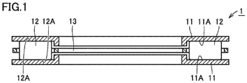
Fig. 1 is a diagram showing a structure in a cross-section along an axial direction of a thrust needle roller bearing 1. -
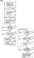
Fig. 2 is a flowchart schematically showing a method of manufacturing a rolling bearing ring according to the present embodiment. -
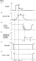
Fig. 3 is a waveform diagram for illustrating variation in various parameters in the method of manufacturing a rolling bearing ring according to the present embodiment. -
Fig. 4 is a diagram schematically showing a shape of a coil material as a steel material. -
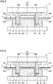
Fig. 5 is a diagram showing a cross-section along a vertical direction of apress machine 3. -
Fig. 6 is a diagram showing apressing portion 35A in a plan view. -
Fig. 7 is a cross-sectional view showing a state that a press die 30 is lowered from a state inFig. 5 to punch a ring-form member. -
Fig. 8 is a cross-sectional view showing a former step of forming performed after punching. -
Fig. 9 is a cross-sectional view showing a latter step of forming performed after punching. -
Fig. 10 is a diagram for illustrating resistance heating representing one example of a heating method. -
Fig. 11 is a diagram for illustrating induction heating representing another example of the heating method. -
Fig. 12 is a diagram for illustrating contact heating representing another example of the heating method. -
Fig. 13 is a first diagram for illustrating a modification of forming. -
Fig. 14 is a second diagram for illustrating the modification of forming. -
Fig. 15 is a diagram for illustrating a manufacturing method (preparation of a steel material) in a comparative example. -
Fig. 16 is a first diagram for illustrating the manufacturing method (punching) in the comparative example. -
Fig. 17 is a second diagram for illustrating the manufacturing method (punching) in the comparative example. -
Fig. 18 is a first diagram for illustrating the manufacturing method (forming) in the comparative example. -
Fig. 19 is a second diagram for illustrating the manufacturing method (forming) in the comparative example. -
Fig. 20 is a first diagram for illustrating the manufacturing method (carburization and quenching) in the comparative example. -
Fig. 21 is a second diagram for illustrating the manufacturing method (carburization and quenching) in the comparative example. -
Fig. 22 is a third diagram for illustrating the manufacturing method (carburization and quenching) in the comparative example. -
Fig. 23 is a diagram for illustrating the manufacturing method (press-tempering) in the comparative example. -
Fig. 24 is a diagram showing a construction of a press machine used for performing the method of manufacturing a rolling bearing ring according to the present embodiment. -
Fig. 25 shows a photograph of a rolling bearing ring according to an Example. -
Fig. 26 shows a photograph of a steel structure in the rolling bearing ring according to the Example. - An embodiment of the present invention will be described hereinafter with reference to the drawings. The same or corresponding elements in the drawings below have the same reference characters allotted and description thereof will not be repeated.
- A construction of a thrust
needle roller bearing 1 according to one embodiment of the present invention will initially be described.Fig. 1 shows a structure in a cross-section along an axial direction of thrustneedle roller bearing 1. Referring toFig. 1 , thrustneedle roller bearing 1 includes a pair of rolling bearing rings 11, a plurality ofneedle rollers 12, and aretainer 13. -
Rolling bearing ring 11 is composed, for example, of steel in which a concentration of carbon is not lower than 0.4 mass %, and is in a disc shape with a hole being provided in the center.Rolling bearing ring 11 has a rolling bearingring raceway surface 11A with which needleroller 12 is in contact at one main surface. The pair of rolling bearing rings 11 is arranged such that rolling bearingring raceway surfaces 11A are opposed to each other. An inner circumferential side of rollingbearing ring 11 is shallowly bent to preventrollers 12 from coming off.Rolling bearing ring 11 has a Vickers hardness not lower than 700 HV.Rolling bearing ring 11 has a flatness at rolling bearingring raceway surface 11A of approximately 10 µm. -
Needle roller 12 is composed, for example, of steel and has a roller rollingcontact surface 12A at an outer circumferential surface. As shown inFig. 1 ,needle roller 12 is arranged between the pair of rolling bearing rings 11 such that roller rollingcontact surface 12A is in contact with rolling bearingring raceway surface 11A. -
Retainer 13 is composed, for example, of a resin, and retains a plurality ofneedle rollers 12 at a prescribed pitch in a circumferential direction of rollingbearing ring 11. More specifically,retainer 13 has a plurality of pockets (not shown) in an annular shape provided at an equal interval in the circumferential direction.Retainer 13 accommodatesneedle roller 13 in the pocket. - A plurality of
needle rollers 12 are rollably retained byretainer 13 on an annular raceway along the circumferential direction of rollingbearing ring 11. With the construction above, thrustneedle roller bearing 1 is constructed such that a pair of rolling bearing rings 11 can rotate relatively to each other.Rolling bearing ring 11 is manufactured with a method of manufacturing a rolling bearing ring according to the present embodiment described below. -
Fig. 2 is a flowchart schematically showing the method of manufacturing a rolling bearing ring according to the present embodiment.Fig. 3 is a time chart for illustrating variation in various parameters in the method of manufacturing a rolling bearing ring according to the present embodiment.Fig. 3 shows (A) change over time in current supplied to a steel material, (B) change over time in temperature of the steel material, (C) a stroke (outer cylinder) of a press machine, (D) an amount of projection of an inner cylinder of the press machine, (E) a pressure of a hydraulic chuck, and (F) tensile force applied between first and second clamping portions. - The method of manufacturing a rolling bearing ring according to the present embodiment will be described below in the order of "S0 to S13" provided in
Figs. 2 and3 mainly with reference to the flowchart inFig. 2 and the time chart inFig. 3 . - Initially, a steel material which is a material for obtaining rolling
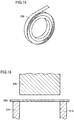
bearing ring 11 is prepared (S0).Fig. 4 is a diagram schematically showing a shape of a coil material as the steel material. As shown inFig. 4 , acoil material 2 is obtained by winding up like a coil, a rolled steel material in a form of a thin plate. -
Coil material 2 is composed of steel containing, for example, at least 0.4 mass % of carbon. More specifically,coil material 2 is composed of steel such as SAE1070 defined under SAE standards, S40C and S45C, S50C, S55C, and S60C defined under JIS as carbon steel for machine structural use, SUJ2 defined under JIS as high carbon chromium bearing steel, SK85 defined under JIS as carbon tool steel, SCM440 and SCM445 defined under JIS as low-alloyed steel for machine structural use, SKS5 defined under JIS as an alloy tool steel, SUP13 defined under JIS as a spring steel, or SUS440C defined under JIS as stainless steel.Coil material 2 is a steel material in a form of a thin plate having a thickness not greater than 2 mm. - Then, a
press machine 3 as a forming table for obtaining rollingbearing ring 11 fromcoil material 2 is prepared (S0) andcoil material 2 is set on press machine 3 (S1). A construction ofpress machine 3 will be illustrated and described here. -
Fig. 5 is a diagram showing a cross-section along a vertical direction (a direction of a stroke of the press) ofpress machine 3.Press machine 3 includes apress die 30, forming dies 31 and 32, and afirst clamping portion 33A and asecond clamping portion 33B. - Press die 30 is in a cylindrical shape. Press die 30 includes an
outer cylinder 30A and aninner cylinder 30B.Outer cylinder 30A andinner cylinder 30B includepressing portions portions coil material 2 between the pressing portions and upper end surfaces of forming dies 31 and 32. Press die 30 is arranged to face forming dies 31 and 32 in the vertical direction. Press die 30 can be caused to make a stroke toward forming dies 31 and 32 or to move away from forming dies 31 and 32 by a not-shown drive mechanism. Forming dies 31 and 32 are fixed to abase 36 of the press machine. -
Fig. 6 is a diagram showingpressing portion 35A in a plan view. As shown with a dashed line inFig. 6 , awater cooling circuit 35C serving as a passage for cooling water is provided inpressing portion 35A along the circumferential direction.Fig. 6 shows an arrow showing a flow of cooling water. By thus coolingpressing portion 35A by circulating cooling water,coil material 2 can rapidly be cooled (die quenched) whenpressing portion 35A is brought in contact withcoil material 2. A passage for cooling water may be provided for cooling not only in pressingportion 35A ofouter cylinder 30A but also similarly in formingdie 32 andpressing portion 35B ofinner cylinder 30B. - Referring again to
Fig. 5 , forming dies 31 and 32 are arranged to face press die 30 in the vertical direction. As shown inFig. 5 , formingdie 31 has a columnar shape. Forming die 32 is in a ring form and has an inner diameter greater than a diameter of formingdie 31. Forming die 32 is arranged outside forming die 31 such that a gap is provided between forming dies 31 and 32 in the radial direction. In formingdie 32, aprojection portion 32A projecting radially inward is formed in an inner circumferential portion thereof. -
Fig. 7 is a cross-sectional view showing a state that press die 30 is lowered from a state inFig. 5 to punch a ring-form member. - As shown in
Fig. 7 , when press die 30 makes a stroke toward forming dies 31 and 32, pressingportions - First clamping
portion 33A andsecond clamping portion 33B serve to fixcoil material 2 onpress machine 3 and to apply tensile force tocoil material 2. First clampingportion 33A andsecond clamping portion 33B are provided to be able to switch between a state in whichcoil material 2 is held in the vertical direction as shown inFig. 7 and a state in which it is not held as shown inFig. 5 . Though first clampingportion 33A andsecond clamping portion 33B may be in any construction, they may be provided, for example, as a hydraulic clamp or an air clamp. - First clamping
portion 33A andsecond clamping portion 33B are provided at positions where they are opposed to each other with press die 30 and forming dies 31 and 32 being interposed in a direction of extension ofcoil material 2. First clampingportion 33A is arranged on a supply side ofcoil material 2 in the direction of extension andsecond clamping portion 33B is arranged on an ejection side ofcoil material 2 in the direction of extension. - First clamping
portion 33A andsecond clamping portion 33B are provided to be relatively movable in the direction opposed to each other (the direction of extension of coil material 2). For example,first clamping portion 33A andsecond clamping portion 33B are each a hydraulic clamp including a hydraulic cylinder (not shown) and movably provided so as to move away from each other in the direction in which they are opposed to each other owing to the hydraulic cylinder. Thus,first clamping portion 33A andsecond clamping portion 33B can apply tensile force in the direction of extension ofcoil material 2 tocoil material 2 arranged between press die 30 and forming dies 31 and 32. Tensile force which can be applied tocoil material 2 by first clampingportion 33A andsecond clamping portion 33B is higher than 0 MPa and not higher than 500 MPa. Tensile force refers to stress in a direction of length of coil material 2 (stress for extendingcoil material 2, specifically, stress applied tocoil material 2 for clampingcoil material 2 for power feed and removing deformation due to thermal expansion). - A power feed terminal is provided for supply of a current to
coil material 2. The power feed terminal is connected to a direct-current (DC) power supply or an alternating-current (AC) power supply which is not shown and supplies a direct current or an alternating current tocoil material 2.Coil material 2 can be heated by heat generation resulting from supply of the current. Though the power feed terminal may be located, for example, on an inner side relative tofirst clamping portion 33A andsecond clamping portion 33B and provided to be able to be in contact with a portion ofcoil material 2 where tensile force is applied by first clampingportion 33A andsecond clamping portion 33B,first clamping portion 33A andsecond clamping portion 33B may also serve as power feed terminals. -
Press machine 3 sequentially operates as shown in the time chart inFig. 3 below. Initially, at time t1,coil material 2 is clamped by first clampingportion 33A andsecond clamping portion 33B of press machine 3 (S2). A pressure P1 for holdingcoil material 2 is supplied tofirst clamping portion 33A andsecond clamping portion 33B. - Then, at time t2, tensile force is applied to coil material 2 (S3). Specifically, at least one of
first clamping portion 33A andsecond clamping portion 33B is relatively moved so as to move away from the other thereof in the direction of extension ofcoil material 2. Thus, incoil material 2, tensile force in accordance with an amount of relative movement offirst clamping portion 33A andsecond clamping portion 33B (an amount of change in distance between first clampingportion 33A andsecond clamping portion 33B) is applied to a region located between respective portions held by first clampingportion 33A andsecond clamping portion 33B. Tensile force applied tocoil material 2 is, for example, higher than 0 MPa and not higher than 500 MPa. Relative positional relation between first clampingportion 33A andsecond clamping portion 33B is held at least until time t8 at which press-forming ends. Tensile force applied tocoil material 2 is held at least during a period in which heating and press-forming are performed. - Then, at time t3, electrical heating is started (S4). Initially, the power feed terminal is moved to be in contact with
coil material 2. Then, a current is supplied tocoil material 2 through the power feed terminal. Thus,coil material 2 is heated by heat generation (Joule heat) resulting from supply of a current (electrical heating). - As a result of feed of a prescribed current for a period between time t3 and time t4, a temperature is increased, and at time t5, a temperature of
coil material 2 reaches a target temperature (S5). The current is lowered at time t4 slightly before the target temperature is reached, andcoil material 2 is held for a certain period of time at the target temperature for a period from time t5 to t6 (S6). At time t6, electrical heating ofcoil material 2 onpress machine 3 is completed (S7). - A heating temperature (target temperature) of
coil material 2 is a temperature not lower than an A1 transformation point of steel formingcoil material 2, and it is, for example, 1000°C. The "A1 transformation point" refers to a point corresponding to a temperature at which a structure of steel starts transformation from ferrite to austenite when steel is heated. Therefore, the structure of steel which makes upcoil material 2 transforms to austenite as a result of electrical heating. - Then, press-forming of
coil material 2 is started (S8). Specifically, at time t7, press die 30 inFig. 7 makes a stroke toward forming dies 31 and 32. At this stage,outer cylinder 30A andinner cylinder 30B integrally make a stroke. Thus,pressing portions coil material 2 and a part ofcoil material 2 is punched into a ring form in the direction of thickness of coil material 2 (S9). A ring-form member 2A in the ring form is thus obtained. Thereafter, at time t8, ring-form member 2A is formed. -
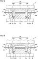
Fig. 8 is a cross-sectional view showing a former step of forming performed after punching.Fig. 9 is a cross-sectional view showing a latter step of forming performed after punching. - At time t8, as press die 30 makes a further stroke toward forming dies 31 and 32, pressing
portion 35A ofouter cylinder 30A is in contact withprojection portion 32A of formingdie 32 and reaches the bottom dead center (S10). The stroke ofouter cylinder 30A remains at rest at the bottom dead center andinner cylinder 30B projects downward fromouter cylinder 30A as shown inFig. 3 (D) . In a state shown inFig. 8 , ring-form member 2A is held betweenpressing portion 35A andprojection portion 32A. Holding force at this time is not lower than 0.2 MPa and preferably not lower than 1 MPa. - Referring further to
Fig. 9 , asinner cylinder 30B projects downward fromouter cylinder 30A, ring-form member 2A is drawn. An inner circumferential portion of ring-form member 2A is bent downward to be oriented in the direction of thickness of ring-form member 2A. Ring-form member 2A is thus subjected to multiple-stage pressing in press machine 3 (S11). As a result of this multiple-stage pressing, whileouter cylinder 30A presses an outer circumferential portion of ring-form member 2A,inner cylinder 30B projects fromouter cylinder 30A and the inner circumferential portion of ring-form member 2A is drawn byinner cylinder 30B, so that a formedobject 2B is formed. By drawing the inner circumferential portion while the outer circumferential portion is pressed, wrinkles or fractures caused in the outer circumferential portion of formedobject 2B can be prevented. Since drawing has to be performed while the temperature of ring-form member 2A is high, drawing should be completed immediately afterouter cylinder 30A reaches the bottom dead center. A time period shown as time t7 to t8 from start of punching until completion of drawing is, for example, within 0.1 second and preferably within 0.02 second. - Then, formed
object 2B is held for a certain period of time from time t8 to t9 while it is in contact with press machine 3 (press die 30 and forming dies 31 and 32). Here, since cooling water is supplied towater cooling circuit 35C in press die 30 as shown inFig. 6 , heat is removed from ring-form member 2A by cooled press die 30. A similar water cooling circuit may be provided also in formingdie 32. Thus, ring-form member 2A is quenched as being rapidly cooled to a temperature not higher than an Ms point. - The "Ms point (martensite transformation point)" refers to a point corresponding to a temperature at which conversion to martensite is started when steel which was converted to austenite is cooled. Consequently, the structure of steel which makes up
formed object 2B transforms into martensite. Quenching of formedobject 2B (die quenching) is thus completed at time t9 (S12). - Finally, at time t10, a pressure supplied to
first clamping portion 33A andsecond clamping portion 33B for holdingcoil material 2 is released andcoil material 2 which is a refuse material and formedobject 2B of which quenching has been completed are taken out ofpress machine 3. Tensile force applied tocoil material 2 is relaxed (S13) by relaxing clamping force between first clampingportion 33A andsecond clamping portion 33B. With the manufacturing method including steps SO to S13 as above, rollingbearing ring 11 is manufactured. - The method of manufacturing a rolling bearing ring according to the present embodiment is not limited as above but can variously be modified.
- For example, in a method of applying tensile force to
coil material 2, both offirst clamping portion 33A andsecond clamping portion 33B may be providedoutside press machine 3. - At least any method selected from the group consisting of indirect resistance heating, induction heating, contact heat transfer, and far-infrared heating can be adopted as the method of
heating coil material 2, without being limited to electrical heating. Each heating method will be described below in further detail. -
Fig. 10 is a diagram for illustrating resistance heating representing one example of a heating method. Two heating methods are available as resistance heating. One is a method of heating aheated object 100 with Joule heat generated as a result of direct power feed toheated object 100 having a resistance R1 as shown inFig. 10 (a) . Another is a method of indirectly heatingheated object 100 arranged around aheat generator 102 having a resistance R2 with Joule heat generated as a result of power feed to heatgenerator 102 as shown inFig. 10 (b) . - Referring to
Fig. 10 (a) , in the method of heatingheated object 100 by direct power feed, a current I is supplied from apower supply 101 toheated object 100 having resistance R1. Thus, heat generation (P = R1·I2) owing to supply of current I occurs inheated object 100 andheated object 100 is heated. In the present embodiment,coil material 2 may be heated by heat generation resulting from supply of a direct current from the power feed terminal tocoil material 2.Coil material 2 may be heated by heat generation resulting from supply of an alternating current from the power feed terminal tocoil material 2. - Referring to
Fig. 10 (b) , in the method of indirectly heatingheated object 100, current I is supplied frompower supply 101 toheat generator 102 having resistance R2. Thus, heat generation (P=R2·I2) resulting from supply of current I occurs inheat generator 102 andheat generator 102 is heated. In the present embodiment, a direct current or an alternating current may be supplied toheat generator 102. -
Fig. 11 is a diagram for illustrating induction heating representing another example of the heating method. Referring toFig. 11 , in induction heating, an alternating current is supplied from anAC power supply 103 to acoil 104 so that an alternating magnetic flux B is produced inheated object 100. An eddy current I is produced inheated object 100 in a direction cancelling alternating magnetic flux B. Then,heated object 100 is heated by heat generation resulting from eddy current I and a resistance R ofheated object 100. -
Fig. 12 is a diagram for illustrating contact heating representing another example of the heating method. Referring toFig. 12 , in contact heat transfer,heated object 100 is heated by heat transfer from aninternal heating roll 106 and anexternal heating roll 105. - Though not shown, in far-infrared heating, far-infrared energy is provided to a heated object by irradiating the heated object with far-infrared rays. Heat generation results from activation of vibration between atoms which make up the heated object and the heated object is thus heated.
- In the method of manufacturing a rolling bearing ring according to the present embodiment, as shown in
Fig. 9 , formedobject 2B is formed inpress machine 3 by bending by drawing the inner circumferential portion of ring-form member 2A so as to be oriented in the direction of thickness of ring-form member 2A, however, limitation thereto is not intended. For example, the outer circumferential portion rather than the inner circumferential portion of ring-form member 2A may be drawn. -
Fig. 13 is a first diagram for illustrating a modification of forming.Fig. 14 is a second diagram for illustrating the modification of forming. - In examples shown in
Figs. 13 and 14 , the outer circumferential portion of ring-form member 2A in the ring form is formed to manufacture a formed object 2C. In this case, aprojection portion 131A projecting radially inward on an inner circumferential surface of a formingdie 131 is formed. Therefore, when apress die 130 makes a stroke as in the embodiment above, the inner circumferential portion of ring-form member 2A in the ring form is held betweenprojection portion 131A and a tip end portion of aninner cylinder 130B. - Then, an
outer cylinder 130A of press die 130 makes a further stroke relative toinner cylinder 130B. Thus, as shown inFig. 14 , the inner circumferential portion of ring-form member 2A is bent by drawing so as to be oriented in the direction of thickness of ring-form member 2A to thereby form formed object 2C. By doing so as well, ring-form member 2A can be formed in the press machine before quenching and an effect the same as in the embodiment above can be achieved. - A function and effect of the method of manufacturing a rolling bearing ring according to the present embodiment will now be described with reference to a comparative example. A method of manufacturing a rolling bearing ring in the comparative example will initially be described with reference to
Figs. 15 to 23 . Referring toFig. 15 , initially, acoil material 200 obtained by winding up like a coil, a rolled steel material in a form of a thin plate is prepared. Then, referring toFigs. 16 and17 ,coil material 200 is set on adie 310 and adie 300 makes a stroke towarddie 310.Coil material 200 is thus punched. A formedobject 200A in a ring form is thus obtained. Then, referring toFigs. 18 and19 , formedobject 200A is set on adie 320 and adie 330 makes a stroke towarddie 320, so that an inner circumferential portion of formedobject 200A is formed. - Then, as shown in
Fig. 20 , in a setup step before heat treatment, a plurality of formedobjects 200A are aligned as being hung over abar 410. Thereafter, these formedobjects 200A are placed in acarburization furnace 400 shown inFig. 21 for carburization of formedobjects 200A. Then, as shown inFig. 22 , carburized formedobjects 200A are cooled by supplyingair blast 420 so that formed objects 200A are quenched. Finally, referring toFig. 23 , quenched formedobject 200A is press-tempered in a temperingfurnace 430. Since the method of manufacturing a rolling bearing ring in the comparative example includes many steps as above, cost for manufacturing a rolling bearing ring is high. - In contrast, in the method of manufacturing a rolling bearing ring according to the present embodiment, steps of heating, punching, forming, and quenching
coil material 2 are all performed as one step onpress machine 3. Therefore, the manufacturing process can be shorter than in the method of manufacturing a rolling bearing ring in the comparative example in which the steps are separately performed. Consequently, cost for manufacturing a rolling bearing ring can further be reduced and a more inexpensive rolling bearing ring can be provided. - In the method of manufacturing a rolling bearing ring according to the present embodiment, in the step of obtaining the rolling bearing ring, the steel material is heated and punched while tensile force is applied to the steel material at least in one direction along the surface of the steel material. Therefore, quality of working of the obtained rolling bearing ring can be improved as compared with an example in which the steel material is heated and punched while no tensile force is applied to the steel material in the step of obtaining the rolling bearing ring.
- In the method of manufacturing a rolling bearing ring according to the present embodiment, forming after punching is performed by drawing in multiple-stage pressing. As a result of multiple-stage pressing, ring-
form member 2A in the ring form is drawn while the outer circumference (or the inner circumference) thereof is pressed. Therefore, wrinkles are less likely, an angle of bending can also be close to a right angle, and working accuracy is satisfactory. - It could be confirmed that rolling
bearing ring 11 manufactured with the method of manufacturing a rolling bearing ring according to the present embodiment had high quality of working as a result of evaluation as below. -
Fig. 24 is a diagram showing a construction of a press machine used for performing the method of manufacturing a rolling bearing ring according to the present embodiment. -
Press machine 3 shown inFig. 24 is constructed such that first clampingportion 33A (which also serves as one power feed terminal) is connected to onecylinder 37 andsecond clamping portion 33B (which also serves as the other power feed terminal) is connected to anothercylinder 37. - While tensile force of 10 MPa was applied to
coil material 2 in the direction of extension with the use ofpress machine 3 shown inFig. 24 ,coil material 2 was subjected to direct resistance heating to 1000°C which was a temperature not lower than the A1 transformation point, and thereafter to die quenching. -
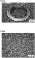
Rolling bearing ring 11 as shown in a photograph inFig. 25 was thus manufactured. A Vickers hardness of a plurality of rolling bearing rings 11 (steel material: SAE1070) thus manufactured was measured, and consequently, an average hardness was approximately 790 HV. A part of rollingbearing ring 11 was cut, a cross-section thereof was corroded with nital, and a microstructure in the cross-section was observed with an optical microscope. Then, a martensite structure as in a photograph inFig. 26 was observed. - A flatness of rolling
bearing ring 11 was measured with the use of Talyrond, and consequently the flatness was approximately 10 µm. In contrast, a rolling bearing ring obtained by heating and punchingcoil material 2 while no tensile force was applied thereto in the step of obtaining a rolling bearing ring in the present embodiment had a flatness of approximately 40 µm. - Thus, it was confirmed that, according to the method of manufacturing a rolling bearing ring according to the present embodiment, the manufacturing process was shortened and rolling
bearing ring 11 high in hardness and quality of working as a result of sufficient quenching could be manufactured. - Finally, the method of manufacturing a rolling bearing ring according to the present embodiment is summarized again with reference to the drawings. Referring to
Figs. 2 and5 , the method of manufacturing a rolling bearing ring according to the present embodiment includes a first step (S1 to S7) of setting a steel material heated to a temperature not lower than the A1 transformation point on a forming table and a second step (S8 to S12) of punching a ring-form member from the steel material and thereafter forming and quenching the ring-form member on the forming table. The forming table includes a first die (forming dies 31 and 32) and a second die (press die 30). The second die is constructed to be dividable intoinner cylinder 30B andouter cylinder 30A. In the second step, ring-form member 2A is punched fromcoil material 2 by arrangingcoil material 2 between the first die and the second die and pressing a tip end portion ofinner cylinder 30B and a tip end portion ofouter cylinder 30A againstcoil material 2. As shown inFigs. 5 to 9 , punched ring-form member 2A is formed and quenched by further pressing a tip end ofinner cylinder 30B against ring-form member 2A while ring-form member 2A is held betweenouter cylinder 30A and formingdie 32. - As shown in the modification, punched ring-
form member 2A may be formed and quenched by further pressing a tip end ofouter cylinder 130A against ring-form member 2A while it is held betweeninner cylinder 130B and formingdie 131. - According to the manufacturing method, punching, forming, and quenching can be performed in a short period of time without requiring an intermediate setup operation. Therefore, manufacturing can be inexpensive and working accuracy in forming is also satisfactory.
- Preferably, in the second step, punching is performed in a first stage and drawing as forming is performed together with quenching in a second stage.
- The manufacturing method is particularly suitable for a shape like a rolling bearing ring.
- More preferably, in the second step, a time period from start of punching of the ring-form member until completion of forming is within 0.1 second.
- Since punching and forming are performed in a short period of time and quenching by die quenching is immediately performed in the manufacturing method, the ring-form member is not gradually cooled before quenching and an effect of quenching is high.
- Preferably, holding force with which the ring-form member is held between any one of the inner cylinder and the outer cylinder and the first die in the second step is not lower than 0.2 MPa.
- Since holding force is thus high, wrinkles or fractures are less likely in drawing.
- Preferably, the steel material contains at least 0.4 mass % of carbon and has a thickness not greater than 2 mm, and a ring form is punched from the steel material in a direction of thickness.
- Since such a steel material is used, quenching is satisfactorily performed and the inside can be quenched also in die-quenching.
- It should be understood that the embodiment disclosed herein is illustrative and non-restrictive in every respect. The scope of the present invention is defined by the terms of the claims, rather than the description of the embodiment above, and is intended to include any modifications within the scope and meaning equivalent to the terms of the claims.
- 1 bearing; 2, 200 coil material; 2A, 2B, 2C, 200A formed object; 3 press machine; 11 rolling bearing ring; 11A rolling bearing ring raceway surface; 12 needle roller; 12A rolling contact surface; 13 retainer; 30, 130 press die; 30A, 130A outer cylinder; 30B, 130B inner cylinder; 31, 32, 131 forming die; 32A, 131A projection portion; 33A first clamping portion; 33B second clamping portion; 35A, 35B pressing portion; 35C water cooling circuit; 37 cylinder; 100 heated object; 101 power supply; 102 heat generator; 103 AC power supply; 104 coil; 105 external heating roll; 106 internal heating roll; 300, 310, 320, 330 die; 400 carburization furnace; and 430 tempering furnace
Claims (6)
- A method of manufacturing a rolling bearing ring comprising:a first step of setting a steel material heated to a temperature not lower than an A1 transformation point on a forming table; anda second step of punching a ring-form member from the steel material and thereafter forming and quenching the ring-form member on the forming table,the forming table including a first die and a second die,the second die being constructed to be dividable into an inner cylinder and an outer cylinder,in the second step, the ring-form member being punched from the steel material by arranging the steel material between the first die and the second die and pressing a tip end portion of the inner cylinder and a tip end portion of the outer cylinder against the steel material, andthe ring-form member being formed and quenched by further pressing a tip end of any one of the inner cylinder and the outer cylinder against the punched ring-form member while the ring-form member is held between any the other of the inner cylinder and the outer cylinder and the first die.
- The method of manufacturing a rolling bearing ring according to claim 1, wherein
in the second step, punching is performed in a first stage and drawing as forming is performed together with quenching in a second stage. - The method of manufacturing a rolling bearing ring according to claim 2, wherein
in the second step, a time period from start of the punching of the ring-form member until completion of the forming is within 0.1 second. - The method of manufacturing a rolling bearing ring according to any one of claims 1 to 3, wherein
holding force with which the ring-form member is held between any one of the inner cylinder and the outer cylinder and the first die in the second step is not lower than 0.2 MPa. - The method of manufacturing a rolling bearing ring according to any one of claims 1 to 4, wherein
the steel material contains at least 0.4 mass % of carbon and has a thickness not greater than 2 mm, and a ring form is punched from the steel material in a direction of thickness. - The method of manufacturing a rolling bearing ring according to any one of claims 1 to 5, wherein
the manufactured rolling bearing ring has a hardness not lower than 700 HV.
Applications Claiming Priority (2)
| Application Number | Priority Date | Filing Date | Title |
|---|---|---|---|
| JP2015176495A JP6537940B2 (en) | 2015-09-08 | 2015-09-08 | Bearing ring manufacturing method |
| PCT/JP2016/074476 WO2017043304A1 (en) | 2015-09-08 | 2016-08-23 | Bearing ring manufacturing method |
Publications (2)
| Publication Number | Publication Date |
|---|---|
| EP3348850A1 true EP3348850A1 (en) | 2018-07-18 |
| EP3348850A4 EP3348850A4 (en) | 2019-05-08 |
Family
ID=58239718
Family Applications (1)
| Application Number | Title | Priority Date | Filing Date |
|---|---|---|---|
| EP16844167.3A Withdrawn EP3348850A4 (en) | 2015-09-08 | 2016-08-23 | Bearing ring manufacturing method |
Country Status (5)
| Country | Link |
|---|---|
| US (1) | US10730098B2 (en) |
| EP (1) | EP3348850A4 (en) |
| JP (1) | JP6537940B2 (en) |
| CN (1) | CN108026972A (en) |
| WO (1) | WO2017043304A1 (en) |
Families Citing this family (4)
| Publication number | Priority date | Publication date | Assignee | Title |
|---|---|---|---|---|
| CN109127998A (en) * | 2018-10-26 | 2019-01-04 | 海安亚鼎机电制造有限公司 | For the manufacture craft of bearer ring |
| EP3999751B1 (en) | 2019-07-15 | 2024-04-17 | The Timken Company | Two-piece composite tapered roller bearing outer ring with interference fit |
| CN111570606B (en) * | 2020-05-22 | 2022-02-22 | 哈尔滨工业大学(威海) | Fine blanking die with integral strength and work hardening of blanking surface and fine blanking method |
| US11904376B2 (en) * | 2020-07-28 | 2024-02-20 | GM Global Technology Operations LLC | Energy-dissipating cover and methods for making the cover |
Family Cites Families (17)
| Publication number | Priority date | Publication date | Assignee | Title |
|---|---|---|---|---|
| JP2747650B2 (en) * | 1994-03-31 | 1998-05-06 | アイダエンジニアリング株式会社 | Plastic working method and apparatus |
| DE19952143A1 (en) | 1998-11-05 | 2000-05-11 | Luk Lamellen & Kupplungsbau | One-piece component forming primary flywheel pressing for fixing on crankshaft of internal combustion engine |
| JP4080182B2 (en) * | 2001-06-25 | 2008-04-23 | Ntn株式会社 | SHELL TYPE NEEDLE ROLLER BEARING AND MANUFACTURING METHOD THEREOF |
| US6658911B2 (en) | 2001-09-25 | 2003-12-09 | Sequa Can Machinery, Inc. | Method and apparatus for forming container end shells |
| CN100406151C (en) * | 2003-09-05 | 2008-07-30 | 株式会社丰技研 | Sheet material stamping forming method and stamping forming device |
| WO2005033346A1 (en) | 2003-10-06 | 2005-04-14 | Ntn Corporation | Thin-walled part producing method, bearing raceway ring, thrust needle roller bearing, rolling bearing raceway ring producing method, rolling bearing raceway ring, and rolling bearing |
| JP4627981B2 (en) * | 2003-12-12 | 2011-02-09 | Ntn株式会社 | Manufacturing method of thin bearing race |
| JP2007170447A (en) * | 2005-12-19 | 2007-07-05 | Ntn Corp | Method for manufacturing raceway ring for thrust roller bearing and device for manufacturing same |
| EP2447558B1 (en) | 2006-06-08 | 2013-05-29 | NSK Ltd. | Method for manufacturing a drawn cup needle roller bearing having a seal ring |
| CN101466957B (en) | 2006-06-08 | 2012-10-03 | 日本精工株式会社 | Drawn cup needle roller bearing with sealing ring and manufacturing method thereof |
| JP2008082435A (en) | 2006-09-27 | 2008-04-10 | Ntn Corp | Thrust roller bearing |
| JP4845813B2 (en) | 2007-06-01 | 2011-12-28 | アイシン高丘株式会社 | Press working equipment in die quench method |
| KR20100019500A (en) | 2007-06-15 | 2010-02-18 | 수미도모 메탈 인더스트리즈, 리미티드 | Process for manufacturing shaped article |
| DE102010033122B4 (en) * | 2010-08-03 | 2015-03-26 | Schaeffler Technologies Gmbh & Co. Kg | Axial rolling bearing, in particular axial needle bearing |
| JP5927018B2 (en) | 2011-04-26 | 2016-05-25 | Ntn株式会社 | Manufacturing method of machine parts |
| JP2013164093A (en) * | 2012-02-09 | 2013-08-22 | Nsk Ltd | Manufacturing method of race for thrust needle bearing |
| CN203649153U (en) | 2013-12-23 | 2014-06-18 | 北汽银翔汽车有限公司 | High-strength steel sheet stamping and hot forming die |
-
2015
- 2015-09-08 JP JP2015176495A patent/JP6537940B2/en not_active Expired - Fee Related
-
2016
- 2016-08-23 WO PCT/JP2016/074476 patent/WO2017043304A1/en not_active Ceased
- 2016-08-23 EP EP16844167.3A patent/EP3348850A4/en not_active Withdrawn
- 2016-08-23 CN CN201680051928.XA patent/CN108026972A/en active Pending
- 2016-08-23 US US15/758,223 patent/US10730098B2/en not_active Expired - Fee Related
Also Published As
| Publication number | Publication date |
|---|---|
| US20180243814A1 (en) | 2018-08-30 |
| WO2017043304A1 (en) | 2017-03-16 |
| JP2017053391A (en) | 2017-03-16 |
| EP3348850A4 (en) | 2019-05-08 |
| JP6537940B2 (en) | 2019-07-03 |
| CN108026972A (en) | 2018-05-11 |
| US10730098B2 (en) | 2020-08-04 |
Similar Documents
| Publication | Publication Date | Title |
|---|---|---|
| EP3167970B1 (en) | Method of manufacturing a rolling bearing ring and rolling bearing ring | |
| US10730098B2 (en) | Method of manufacturing rolling bearing ring | |
| EP3428467A1 (en) | Bearing ring manufacturing method | |
| US20200238360A1 (en) | Method of processing steel plate and punching machine | |
| JP2012517901A (en) | Method for manufacturing press-hardened metal components | |
| JP6758913B2 (en) | Orbital ring manufacturing method | |
| US11786951B2 (en) | Manufacturing method for metal component and manufacturing apparatus for metal component | |
| CN101107369A (en) | Method for manufacturing hot-formed steel product | |
| JP6423740B2 (en) | Manufacturing method of bearing ring | |
| CN102179464A (en) | Process for forming generator claw pole of vehicle | |
| JP6426385B2 (en) | Bearing ring manufacturing method | |
| JP2018167301A (en) | Machine component manufacturing method | |
| JP2013013907A (en) | Warm press forming method for metal plate | |
| DE102016107946B4 (en) | Method for manufacturing a hollow component, component and press for manufacturing a hollow component | |
| JP2017159354A (en) | Manufacturing method of raceway ring | |
| JP2019018215A (en) | Electromagnetic forming method of aluminum material | |
| JP6522444B2 (en) | Bearing ring manufacturing method | |
| CN108971890B (en) | Method for processing check ring | |
| CN204276646U (en) | Hot forming steel plate pierce punch dull die can be reduced | |
| JP2008284599A (en) | Manufacturing method of high strength steel | |
| US20250121423A1 (en) | Press system and method of manufacturing hot stamped structural component | |
| JP2017074612A (en) | Pipe expansion machine | |
| JP2019070176A (en) | Rolling sliding member and method for manufacturing the same and rolling bearing using the rolling sliding member | |
| JP2000237837A (en) | Heat treatment method of hollow cylinder for hollow roll | |
| JP2023142725A (en) | Manufacturing method of bearing parts |
Legal Events
| Date | Code | Title | Description |
|---|---|---|---|
| STAA | Information on the status of an ep patent application or granted ep patent |
Free format text: STATUS: THE INTERNATIONAL PUBLICATION HAS BEEN MADE |
|
| PUAI | Public reference made under article 153(3) epc to a published international application that has entered the european phase |
Free format text: ORIGINAL CODE: 0009012 |
|
| STAA | Information on the status of an ep patent application or granted ep patent |
Free format text: STATUS: REQUEST FOR EXAMINATION WAS MADE |
|
| 17P | Request for examination filed |
Effective date: 20180329 |
|
| AK | Designated contracting states |
Kind code of ref document: A1 Designated state(s): AL AT BE BG CH CY CZ DE DK EE ES FI FR GB GR HR HU IE IS IT LI LT LU LV MC MK MT NL NO PL PT RO RS SE SI SK SM TR |
|
| AX | Request for extension of the european patent |
Extension state: BA ME |
|
| DAV | Request for validation of the european patent (deleted) | ||
| DAX | Request for extension of the european patent (deleted) | ||
| RIC1 | Information provided on ipc code assigned before grant |
Ipc: B21D 53/10 20060101ALI20190220BHEP Ipc: B21D 25/00 20060101ALI20190220BHEP Ipc: C21D 9/40 20060101ALI20190220BHEP Ipc: F16C 33/64 20060101AFI20190220BHEP Ipc: B21D 22/02 20060101ALI20190220BHEP Ipc: B21D 28/02 20060101ALI20190220BHEP Ipc: F16C 19/30 20060101ALI20190220BHEP Ipc: F16C 19/46 20060101ALI20190220BHEP Ipc: C21D 1/18 20060101ALI20190220BHEP Ipc: C21D 1/42 20060101ALI20190220BHEP Ipc: B21D 24/16 20060101ALI20190220BHEP Ipc: B21D 28/00 20060101ALI20190220BHEP Ipc: C21D 9/00 20060101ALI20190220BHEP Ipc: B21D 19/08 20060101ALI20190220BHEP Ipc: B21D 53/16 20060101ALI20190220BHEP Ipc: C21D 1/40 20060101ALI20190220BHEP Ipc: B21D 22/06 20060101ALI20190220BHEP |
|
| RIC1 | Information provided on ipc code assigned before grant |
Ipc: B21D 53/10 20060101ALI20190227BHEP Ipc: C21D 1/40 20060101ALI20190227BHEP Ipc: B21D 19/08 20060101ALI20190227BHEP Ipc: B21D 28/00 20060101ALI20190227BHEP Ipc: B21D 25/00 20060101ALI20190227BHEP Ipc: F16C 33/64 20060101AFI20190227BHEP Ipc: F16C 19/46 20060101ALI20190227BHEP Ipc: B21D 22/02 20060101ALI20190227BHEP Ipc: B21D 28/02 20060101ALI20190227BHEP Ipc: F16C 19/30 20060101ALI20190227BHEP Ipc: C21D 9/00 20060101ALI20190227BHEP Ipc: B21D 53/16 20060101ALI20190227BHEP Ipc: B21D 22/06 20060101ALI20190227BHEP Ipc: C21D 9/40 20060101ALI20190227BHEP Ipc: C21D 1/18 20060101ALI20190227BHEP Ipc: B21D 24/16 20060101ALI20190227BHEP Ipc: C21D 1/42 20060101ALI20190227BHEP |
|
| A4 | Supplementary search report drawn up and despatched |
Effective date: 20190408 |
|
| RIC1 | Information provided on ipc code assigned before grant |
Ipc: F16C 33/64 20060101AFI20190402BHEP Ipc: B21D 22/06 20060101ALI20190402BHEP Ipc: C21D 9/40 20060101ALI20190402BHEP Ipc: B21D 53/16 20060101ALI20190402BHEP Ipc: B21D 28/00 20060101ALI20190402BHEP Ipc: C21D 9/00 20060101ALI20190402BHEP Ipc: F16C 19/46 20060101ALI20190402BHEP Ipc: F16C 19/30 20060101ALI20190402BHEP Ipc: B21D 28/02 20060101ALI20190402BHEP Ipc: C21D 1/40 20060101ALI20190402BHEP Ipc: B21D 25/00 20060101ALI20190402BHEP Ipc: B21D 22/02 20060101ALI20190402BHEP Ipc: B21D 19/08 20060101ALI20190402BHEP Ipc: C21D 1/18 20060101ALI20190402BHEP Ipc: C21D 1/42 20060101ALI20190402BHEP Ipc: B21D 24/16 20060101ALI20190402BHEP Ipc: B21D 53/10 20060101ALI20190402BHEP |
|
| STAA | Information on the status of an ep patent application or granted ep patent |
Free format text: STATUS: THE APPLICATION HAS BEEN WITHDRAWN |
|
| 18W | Application withdrawn |
Effective date: 20200603 |