EP3348823A1 - Control device - Google Patents
Control device Download PDFInfo
- Publication number
- EP3348823A1 EP3348823A1 EP16844072.5A EP16844072A EP3348823A1 EP 3348823 A1 EP3348823 A1 EP 3348823A1 EP 16844072 A EP16844072 A EP 16844072A EP 3348823 A1 EP3348823 A1 EP 3348823A1
- Authority
- EP
- European Patent Office
- Prior art keywords
- internal combustion
- combustion engine
- fuel
- purge
- control unit
- Prior art date
- Legal status (The legal status is an assumption and is not a legal conclusion. Google has not performed a legal analysis and makes no representation as to the accuracy of the status listed.)
- Granted
Links
Images


Classifications
-
- F—MECHANICAL ENGINEERING; LIGHTING; HEATING; WEAPONS; BLASTING
- F02—COMBUSTION ENGINES; HOT-GAS OR COMBUSTION-PRODUCT ENGINE PLANTS
- F02D—CONTROLLING COMBUSTION ENGINES
- F02D41/00—Electrical control of supply of combustible mixture or its constituents
- F02D41/0025—Controlling engines characterised by use of non-liquid fuels, pluralities of fuels, or non-fuel substances added to the combustible mixtures
- F02D41/003—Adding fuel vapours, e.g. drawn from engine fuel reservoir
- F02D41/0032—Controlling the purging of the canister as a function of the engine operating conditions
- F02D41/004—Control of the valve or purge actuator, e.g. duty cycle, closed loop control of position
-
- B—PERFORMING OPERATIONS; TRANSPORTING
- B60—VEHICLES IN GENERAL
- B60W—CONJOINT CONTROL OF VEHICLE SUB-UNITS OF DIFFERENT TYPE OR DIFFERENT FUNCTION; CONTROL SYSTEMS SPECIALLY ADAPTED FOR HYBRID VEHICLES; ROAD VEHICLE DRIVE CONTROL SYSTEMS FOR PURPOSES NOT RELATED TO THE CONTROL OF A PARTICULAR SUB-UNIT
- B60W10/00—Conjoint control of vehicle sub-units of different type or different function
- B60W10/02—Conjoint control of vehicle sub-units of different type or different function including control of driveline clutches
-
- B—PERFORMING OPERATIONS; TRANSPORTING
- B60—VEHICLES IN GENERAL
- B60W—CONJOINT CONTROL OF VEHICLE SUB-UNITS OF DIFFERENT TYPE OR DIFFERENT FUNCTION; CONTROL SYSTEMS SPECIALLY ADAPTED FOR HYBRID VEHICLES; ROAD VEHICLE DRIVE CONTROL SYSTEMS FOR PURPOSES NOT RELATED TO THE CONTROL OF A PARTICULAR SUB-UNIT
- B60W10/00—Conjoint control of vehicle sub-units of different type or different function
- B60W10/04—Conjoint control of vehicle sub-units of different type or different function including control of propulsion units
- B60W10/06—Conjoint control of vehicle sub-units of different type or different function including control of propulsion units including control of combustion engines
-
- B—PERFORMING OPERATIONS; TRANSPORTING
- B60—VEHICLES IN GENERAL
- B60W—CONJOINT CONTROL OF VEHICLE SUB-UNITS OF DIFFERENT TYPE OR DIFFERENT FUNCTION; CONTROL SYSTEMS SPECIALLY ADAPTED FOR HYBRID VEHICLES; ROAD VEHICLE DRIVE CONTROL SYSTEMS FOR PURPOSES NOT RELATED TO THE CONTROL OF A PARTICULAR SUB-UNIT
- B60W30/00—Purposes of road vehicle drive control systems not related to the control of a particular sub-unit, e.g. of systems using conjoint control of vehicle sub-units
- B60W30/18—Propelling the vehicle
- B60W30/18009—Propelling the vehicle related to particular drive situations
- B60W30/18072—Coasting
-
- F—MECHANICAL ENGINEERING; LIGHTING; HEATING; WEAPONS; BLASTING
- F02—COMBUSTION ENGINES; HOT-GAS OR COMBUSTION-PRODUCT ENGINE PLANTS
- F02D—CONTROLLING COMBUSTION ENGINES
- F02D29/00—Controlling engines, such controlling being peculiar to the devices driven thereby, the devices being other than parts or accessories essential to engine operation, e.g. controlling of engines by signals external thereto
- F02D29/02—Controlling engines, such controlling being peculiar to the devices driven thereby, the devices being other than parts or accessories essential to engine operation, e.g. controlling of engines by signals external thereto peculiar to engines driving vehicles; peculiar to engines driving variable pitch propellers
-
- F—MECHANICAL ENGINEERING; LIGHTING; HEATING; WEAPONS; BLASTING
- F02—COMBUSTION ENGINES; HOT-GAS OR COMBUSTION-PRODUCT ENGINE PLANTS
- F02D—CONTROLLING COMBUSTION ENGINES
- F02D29/00—Controlling engines, such controlling being peculiar to the devices driven thereby, the devices being other than parts or accessories essential to engine operation, e.g. controlling of engines by signals external thereto
- F02D29/04—Controlling engines, such controlling being peculiar to the devices driven thereby, the devices being other than parts or accessories essential to engine operation, e.g. controlling of engines by signals external thereto peculiar to engines driving pumps
-
- F—MECHANICAL ENGINEERING; LIGHTING; HEATING; WEAPONS; BLASTING
- F02—COMBUSTION ENGINES; HOT-GAS OR COMBUSTION-PRODUCT ENGINE PLANTS
- F02D—CONTROLLING COMBUSTION ENGINES
- F02D29/00—Controlling engines, such controlling being peculiar to the devices driven thereby, the devices being other than parts or accessories essential to engine operation, e.g. controlling of engines by signals external thereto
- F02D29/06—Controlling engines, such controlling being peculiar to the devices driven thereby, the devices being other than parts or accessories essential to engine operation, e.g. controlling of engines by signals external thereto peculiar to engines driving electric generators
-
- F—MECHANICAL ENGINEERING; LIGHTING; HEATING; WEAPONS; BLASTING
- F02—COMBUSTION ENGINES; HOT-GAS OR COMBUSTION-PRODUCT ENGINE PLANTS
- F02D—CONTROLLING COMBUSTION ENGINES
- F02D41/00—Electrical control of supply of combustible mixture or its constituents
- F02D41/0025—Controlling engines characterised by use of non-liquid fuels, pluralities of fuels, or non-fuel substances added to the combustible mixtures
- F02D41/003—Adding fuel vapours, e.g. drawn from engine fuel reservoir
- F02D41/0032—Controlling the purging of the canister as a function of the engine operating conditions
-
- F—MECHANICAL ENGINEERING; LIGHTING; HEATING; WEAPONS; BLASTING
- F02—COMBUSTION ENGINES; HOT-GAS OR COMBUSTION-PRODUCT ENGINE PLANTS
- F02D—CONTROLLING COMBUSTION ENGINES
- F02D41/00—Electrical control of supply of combustible mixture or its constituents
- F02D41/02—Circuit arrangements for generating control signals
- F02D41/021—Introducing corrections for particular conditions exterior to the engine
- F02D41/0215—Introducing corrections for particular conditions exterior to the engine in relation with elements of the transmission
- F02D41/022—Introducing corrections for particular conditions exterior to the engine in relation with elements of the transmission in relation with the clutch status
-
- F—MECHANICAL ENGINEERING; LIGHTING; HEATING; WEAPONS; BLASTING
- F02—COMBUSTION ENGINES; HOT-GAS OR COMBUSTION-PRODUCT ENGINE PLANTS
- F02D—CONTROLLING COMBUSTION ENGINES
- F02D41/00—Electrical control of supply of combustible mixture or its constituents
- F02D41/02—Circuit arrangements for generating control signals
- F02D41/04—Introducing corrections for particular operating conditions
- F02D41/042—Introducing corrections for particular operating conditions for stopping the engine
-
- F—MECHANICAL ENGINEERING; LIGHTING; HEATING; WEAPONS; BLASTING
- F02—COMBUSTION ENGINES; HOT-GAS OR COMBUSTION-PRODUCT ENGINE PLANTS
- F02D—CONTROLLING COMBUSTION ENGINES
- F02D41/00—Electrical control of supply of combustible mixture or its constituents
- F02D41/02—Circuit arrangements for generating control signals
- F02D41/04—Introducing corrections for particular operating conditions
- F02D41/08—Introducing corrections for particular operating conditions for idling
-
- F—MECHANICAL ENGINEERING; LIGHTING; HEATING; WEAPONS; BLASTING
- F02—COMBUSTION ENGINES; HOT-GAS OR COMBUSTION-PRODUCT ENGINE PLANTS
- F02D—CONTROLLING COMBUSTION ENGINES
- F02D41/00—Electrical control of supply of combustible mixture or its constituents
- F02D41/02—Circuit arrangements for generating control signals
- F02D41/04—Introducing corrections for particular operating conditions
- F02D41/12—Introducing corrections for particular operating conditions for deceleration
-
- F—MECHANICAL ENGINEERING; LIGHTING; HEATING; WEAPONS; BLASTING
- F02—COMBUSTION ENGINES; HOT-GAS OR COMBUSTION-PRODUCT ENGINE PLANTS
- F02D—CONTROLLING COMBUSTION ENGINES
- F02D41/00—Electrical control of supply of combustible mixture or its constituents
- F02D41/30—Controlling fuel injection
-
- F—MECHANICAL ENGINEERING; LIGHTING; HEATING; WEAPONS; BLASTING
- F02—COMBUSTION ENGINES; HOT-GAS OR COMBUSTION-PRODUCT ENGINE PLANTS
- F02M—SUPPLYING COMBUSTION ENGINES IN GENERAL WITH COMBUSTIBLE MIXTURES OR CONSTITUENTS THEREOF
- F02M25/00—Engine-pertinent apparatus for adding non-fuel substances or small quantities of secondary fuel to combustion-air, main fuel or fuel-air mixture
- F02M25/08—Engine-pertinent apparatus for adding non-fuel substances or small quantities of secondary fuel to combustion-air, main fuel or fuel-air mixture adding fuel vapours drawn from engine fuel reservoir
-
- B—PERFORMING OPERATIONS; TRANSPORTING
- B60—VEHICLES IN GENERAL
- B60W—CONJOINT CONTROL OF VEHICLE SUB-UNITS OF DIFFERENT TYPE OR DIFFERENT FUNCTION; CONTROL SYSTEMS SPECIALLY ADAPTED FOR HYBRID VEHICLES; ROAD VEHICLE DRIVE CONTROL SYSTEMS FOR PURPOSES NOT RELATED TO THE CONTROL OF A PARTICULAR SUB-UNIT
- B60W2510/00—Input parameters relating to a particular sub-units
- B60W2510/02—Clutches
- B60W2510/0208—Clutch engagement state, e.g. engaged or disengaged
-
- B—PERFORMING OPERATIONS; TRANSPORTING
- B60—VEHICLES IN GENERAL
- B60W—CONJOINT CONTROL OF VEHICLE SUB-UNITS OF DIFFERENT TYPE OR DIFFERENT FUNCTION; CONTROL SYSTEMS SPECIALLY ADAPTED FOR HYBRID VEHICLES; ROAD VEHICLE DRIVE CONTROL SYSTEMS FOR PURPOSES NOT RELATED TO THE CONTROL OF A PARTICULAR SUB-UNIT
- B60W2510/00—Input parameters relating to a particular sub-units
- B60W2510/06—Combustion engines, Gas turbines
- B60W2510/0638—Engine speed
- B60W2510/0647—Coasting condition
-
- B—PERFORMING OPERATIONS; TRANSPORTING
- B60—VEHICLES IN GENERAL
- B60W—CONJOINT CONTROL OF VEHICLE SUB-UNITS OF DIFFERENT TYPE OR DIFFERENT FUNCTION; CONTROL SYSTEMS SPECIALLY ADAPTED FOR HYBRID VEHICLES; ROAD VEHICLE DRIVE CONTROL SYSTEMS FOR PURPOSES NOT RELATED TO THE CONTROL OF A PARTICULAR SUB-UNIT
- B60W2520/00—Input parameters relating to overall vehicle dynamics
- B60W2520/04—Vehicle stop
-
- B—PERFORMING OPERATIONS; TRANSPORTING
- B60—VEHICLES IN GENERAL
- B60W—CONJOINT CONTROL OF VEHICLE SUB-UNITS OF DIFFERENT TYPE OR DIFFERENT FUNCTION; CONTROL SYSTEMS SPECIALLY ADAPTED FOR HYBRID VEHICLES; ROAD VEHICLE DRIVE CONTROL SYSTEMS FOR PURPOSES NOT RELATED TO THE CONTROL OF A PARTICULAR SUB-UNIT
- B60W2540/00—Input parameters relating to occupants
- B60W2540/10—Accelerator pedal position
- B60W2540/103—Accelerator thresholds, e.g. kickdown
-
- B—PERFORMING OPERATIONS; TRANSPORTING
- B60—VEHICLES IN GENERAL
- B60W—CONJOINT CONTROL OF VEHICLE SUB-UNITS OF DIFFERENT TYPE OR DIFFERENT FUNCTION; CONTROL SYSTEMS SPECIALLY ADAPTED FOR HYBRID VEHICLES; ROAD VEHICLE DRIVE CONTROL SYSTEMS FOR PURPOSES NOT RELATED TO THE CONTROL OF A PARTICULAR SUB-UNIT
- B60W2710/00—Output or target parameters relating to a particular sub-units
- B60W2710/02—Clutches
- B60W2710/021—Clutch engagement state
-
- B—PERFORMING OPERATIONS; TRANSPORTING
- B60—VEHICLES IN GENERAL
- B60W—CONJOINT CONTROL OF VEHICLE SUB-UNITS OF DIFFERENT TYPE OR DIFFERENT FUNCTION; CONTROL SYSTEMS SPECIALLY ADAPTED FOR HYBRID VEHICLES; ROAD VEHICLE DRIVE CONTROL SYSTEMS FOR PURPOSES NOT RELATED TO THE CONTROL OF A PARTICULAR SUB-UNIT
- B60W2710/00—Output or target parameters relating to a particular sub-units
- B60W2710/06—Combustion engines, Gas turbines
- B60W2710/0616—Position of fuel or air injector
- B60W2710/0622—Air-fuel ratio
-
- B—PERFORMING OPERATIONS; TRANSPORTING
- B60—VEHICLES IN GENERAL
- B60W—CONJOINT CONTROL OF VEHICLE SUB-UNITS OF DIFFERENT TYPE OR DIFFERENT FUNCTION; CONTROL SYSTEMS SPECIALLY ADAPTED FOR HYBRID VEHICLES; ROAD VEHICLE DRIVE CONTROL SYSTEMS FOR PURPOSES NOT RELATED TO THE CONTROL OF A PARTICULAR SUB-UNIT
- B60W2710/00—Output or target parameters relating to a particular sub-units
- B60W2710/06—Combustion engines, Gas turbines
- B60W2710/0644—Engine speed
- B60W2710/065—Idle condition
-
- B—PERFORMING OPERATIONS; TRANSPORTING
- B60—VEHICLES IN GENERAL
- B60W—CONJOINT CONTROL OF VEHICLE SUB-UNITS OF DIFFERENT TYPE OR DIFFERENT FUNCTION; CONTROL SYSTEMS SPECIALLY ADAPTED FOR HYBRID VEHICLES; ROAD VEHICLE DRIVE CONTROL SYSTEMS FOR PURPOSES NOT RELATED TO THE CONTROL OF A PARTICULAR SUB-UNIT
- B60W2710/00—Output or target parameters relating to a particular sub-units
- B60W2710/06—Combustion engines, Gas turbines
- B60W2710/0644—Engine speed
- B60W2710/0655—Coasting condition
-
- B—PERFORMING OPERATIONS; TRANSPORTING
- B60—VEHICLES IN GENERAL
- B60W—CONJOINT CONTROL OF VEHICLE SUB-UNITS OF DIFFERENT TYPE OR DIFFERENT FUNCTION; CONTROL SYSTEMS SPECIALLY ADAPTED FOR HYBRID VEHICLES; ROAD VEHICLE DRIVE CONTROL SYSTEMS FOR PURPOSES NOT RELATED TO THE CONTROL OF A PARTICULAR SUB-UNIT
- B60W2710/00—Output or target parameters relating to a particular sub-units
- B60W2710/30—Auxiliary equipments
- B60W2710/305—Auxiliary equipments target power to auxiliaries
-
- F—MECHANICAL ENGINEERING; LIGHTING; HEATING; WEAPONS; BLASTING
- F02—COMBUSTION ENGINES; HOT-GAS OR COMBUSTION-PRODUCT ENGINE PLANTS
- F02D—CONTROLLING COMBUSTION ENGINES
- F02D2200/00—Input parameters for engine control
- F02D2200/02—Input parameters for engine control the parameters being related to the engine
- F02D2200/06—Fuel or fuel supply system parameters
-
- F—MECHANICAL ENGINEERING; LIGHTING; HEATING; WEAPONS; BLASTING
- F02—COMBUSTION ENGINES; HOT-GAS OR COMBUSTION-PRODUCT ENGINE PLANTS
- F02D—CONTROLLING COMBUSTION ENGINES
- F02D2200/00—Input parameters for engine control
- F02D2200/60—Input parameters for engine control said parameters being related to the driver demands or status
- F02D2200/602—Pedal position
-
- F—MECHANICAL ENGINEERING; LIGHTING; HEATING; WEAPONS; BLASTING
- F02—COMBUSTION ENGINES; HOT-GAS OR COMBUSTION-PRODUCT ENGINE PLANTS
- F02D—CONTROLLING COMBUSTION ENGINES
- F02D41/00—Electrical control of supply of combustible mixture or its constituents
- F02D41/02—Circuit arrangements for generating control signals
- F02D41/14—Introducing closed-loop corrections
- F02D41/1438—Introducing closed-loop corrections using means for determining characteristics of the combustion gases; Sensors therefor
- F02D41/1444—Introducing closed-loop corrections using means for determining characteristics of the combustion gases; Sensors therefor characterised by the characteristics of the combustion gases
- F02D41/1454—Introducing closed-loop corrections using means for determining characteristics of the combustion gases; Sensors therefor characterised by the characteristics of the combustion gases the characteristics being an oxygen content or concentration or the air-fuel ratio
-
- Y—GENERAL TAGGING OF NEW TECHNOLOGICAL DEVELOPMENTS; GENERAL TAGGING OF CROSS-SECTIONAL TECHNOLOGIES SPANNING OVER SEVERAL SECTIONS OF THE IPC; TECHNICAL SUBJECTS COVERED BY FORMER USPC CROSS-REFERENCE ART COLLECTIONS [XRACs] AND DIGESTS
- Y02—TECHNOLOGIES OR APPLICATIONS FOR MITIGATION OR ADAPTATION AGAINST CLIMATE CHANGE
- Y02T—CLIMATE CHANGE MITIGATION TECHNOLOGIES RELATED TO TRANSPORTATION
- Y02T10/00—Road transport of goods or passengers
- Y02T10/60—Other road transportation technologies with climate change mitigation effect
Definitions
- the present invention relates to a control device, and more particularly, relates to an evaporative fuel purge control technique of an internal combustion engine.
- PTL 1 discloses a method for stopping fuel injection to an internal combustion engine by way of idling stop, and performing evaporative fuel purge during a period in which an internal combustion engine rotational speed becomes a predetermined value or less to realize both of reduction of fuel consumption by way of idling stop and evaporative fuel purge.
- An object of the present invention is to achieve sufficient evaporative fuel purge while achieving a fuel efficiency effect by stopping an engine by way of idling stop even when the evaporative fuel is frequently generated in a fuel tank or the evaporative fuel greatly accumulates in a canister.
- a control device includes: a purge control unit which controls a purge valve which emits a volatile fuel of a fuel tank or a canister to an intake pipe of an internal combustion engine; and a power transmission control unit which controls a power transmission mechanism between the internal combustion engine and a drive wheel, and, in a state where the power transmission control unit disconnects a clutch, and the vehicle is coasting, the purge control unit opens the evaporative fuel valve and purges the evaporative fuel to the intake pipe.
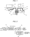
- FIG. 1 is a view illustrating an example of a purge control system of an internal combustion engine.
- an engine controller 114 controls an opening degree of a purge valve 106 and burn the evaporative fuel in an internal combustion engine 101.
- the engine controller 114 estimates an evaporative fuel accumulation amount accumulated in a canister 112 during stop of the internal combustion engine or a volatile fuel amount generated in the fuel tank 109 during an operation of the internal combustion engine 101, and, while an opening of a throttle 102 is small and a negative pressure is generated in an intake pipe 103, opens the purge control valve 106 and purges the evaporative fuel to the intake pipe 103 via connecting pipes 110 and 111.
- a drain valve 108 is closed when leakage of an evaporative fuel from the fuel tank is detected.
- purge control is performed during the operation of the engine, and therefore the drain valve 108 is almost in an opened state.
- a purge system can prevent the evaporative fuel generated in the fuel tank from leaking to the atmosphere.
- FIG. 2 illustrates an example of a purge control calculation block.
- An evaporative fuel concentration calculating unit 201 estimates the generation amount of evaporative fuel from the tank temperature and the remaining fuel amount, takes into account a correction coefficient of air-fuel ratio FB control when the purge valve is opened, and calculates a ratio of (evaporative fuel concentration) of the volatile fuel and air included in the purge emitted from the purge valve.
- a purge duty calculating unit 202 calculates an evaporative fuel flow rate (purge flow rate) which contributes to a target evaporative fuel combustion from the evaporative fuel concentration and the throttle opening to prevent an output of the internal combustion engine and a combustion air-fuel ratio from fluctuating greatly.
- the purge duty calculating unit 202 outputs the purge valve drive duty to prevent fluctuation of the purge flow rate from making the combustion of the internal combustion engine unstable.
- a purge air-fuel ratio correction coefficient calculating unit 203 makes correction to decrease an injector fuel injection amount by the amount that the combustion air-fuel ratio becomes rich by the evaporative fuel. Therefore, the purge air-fuel ratio correction coefficient calculating unit 203 calculates a purge air-fuel ratio correction coefficient (a rate of a decrease in the injector injection fuel) from the evaporative fuel concentration and the throttle opening.
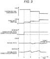
- FIG. 3 illustrates an example of a time chart during purge control.
- the present embodiment describes a case where the throttle opening is constant, a load of the internal combustion engine does not changed, either, the evaporative fuel concentration is high (e.g., 40% or more), the purge valve is opened large at a time, and an engine stalls. At a time A, the purge valve drive duty is increased to start purging the evaporative fuel.
- the air-fuel ratio feedback control increases the air-fuel ratio correction coefficient and lowers the evaporative fuel concentration (e.g., when the air-fuel ratio correction coefficient changes by approximately 10% on average), the evaporative fuel concentration is reduced, and the purge valve 106 is opened to control the purge flow rate to a predetermined value.
- the purge flow rate is determined by the throttle opening and the rotational speed of the internal combustion engine.
- the present embodiment discloses a solution which uses the idling driving (sailing idling driving) during coasting/deceleration.
- FIG. 4 illustrates an example of a power transmission control system which performs sailing idling driving.
- the power generated by an internal combustion engine 404 transmits to a drive wheel 403 via a torque converter 405, a clutch 406, and a CVT transmission 402.
- the power of the internal combustion engine 404 does not transmit to the drive wheel 403, and is used to coast or decelerate the vehicle.
- a transmission controller 401 disconnects the clutch 406 while the drive wheel 403 is rotating (driving), and the internal combustion engine 404 is controlled to the idling rotational speed.
- a compressor 408 of a generator and an air-conditioner is driven by a belt 407 even during the sailing driving. Therefore, by controlling these operating loads, it is possible to increase the internal combustion engine load during the sailing idling driving.
- the present embodiment will be described by using the CVT transmission. However, the present invention can be realized by using a transmission such as AMT or MT.
- FIG. 5 illustrates an example of a flowchart for realizing the present embodiment.
- step S501 whether or not a purge request is made is decided. For example, whether or not the purge request is made is decided based on whether or not the evaporative fuel concentration calculated by the engine controller 114 in FIG. 1 is higher than a predetermined value.
- the flow moves to step S502.
- step S502 in case of a sailing condition (e.g., the vehicle is driving and the accelerator opening is 0), the vehicle transitions to the coasting/decelerating state. That is, when the value of the accelerator opening sensor becomes the predetermined value or less as the sailing driving condition, it is desirable that the power transmission control unit disconnects the clutch 406 and the vehicle coasts.
- a sailing condition e.g., the vehicle is driving and the accelerator opening is 0
- a sailing condition different from step S502 is a request from cruise control. More specifically, while the cruise control is executed, a vehicle acceleration/deceleration command may be used in place of the accelerator opening. For example, at a time when there is no acceleration command, it may be determined that the sailing condition holds. If the sailing condition holds in step S502, the flow moves to step S503. In step S503, the transmission controller 401 in FIG. 4 performs control to transition to the sailing idling driving. The purge control as described in FIGS. 1 to 4 is performed.
- the control device includes a purge control unit (engine controller 114) which controls the purge valve 106 which emits a volatile fuel of the fuel tank 104 or the canister 112 to the intake pipe 103 of the internal combustion engine 101, and a power transmission control unit (transmission controller 401) which controls a power transmission mechanism (clutch 406) between the internal combustion engine 101 and the drive wheel 403. Further, in a state where the power transmission control unit disconnects the power transmission mechanism (the clutch 406 or a lock-up clutch of the torque converter 405) and the vehicle is coasting, the purge control unit (engine controller 114) opens the purge valve 106 and performs control to emit the evaporative fuel to the intake pipe 103. This evaporative fuel is desirably controlled to be emitted to the intake pipe 103 in a state where the power transmission control unit disconnects the power transmission mechanism and the vehicle is coasting and when an evaporative fuel emission request is made.
- engine controller 114 controls the purge valve 106 which emits a volatile fuel of the fuel tank
- a signal of the evaporative fuel emission request is desirably set to be sent when at least one of a volatile fuel concentration value in the fuel tank, a volatile fuel accumulation value of the canister and an evaporative fuel concentration value emitted from the purge valve becomes a predetermined value or more.
- the engine controller 114 and the transmission controller 401 are described as separate components. However, these controllers may be integrated.
- the purge control unit (engine controller 114) opens the purge valve 106 and performs control to emit the evaporative fuel to the intake pipe 103. It is desirable to set this predetermined rotational speed higher than the idling rotational speed while the vehicle stops.
- FIG. 6 illustrates an example of a purge control time chart during sailing idling.
- a control method for starting purging the evaporative fuel during the sailing idling driving will be described.
- the purge request threshold e.g. 10%
- the purge drive duty is set to 0 to close the purge valve is closed.
- the fuel injection is stopped.
- the clutch is disconnected.
- the fuel is injected again to transition to the sailing idling driving.
- the purge valve drive duty is controlled to purge the evaporative fuel. According to this control, a transition to the sailing idling is made by burning the purge fuel and transitioning to sailing idling. Consequently, it is possible to suppress emission deterioration due to the remaining purge fuel before the transition to sailing idling, and rotation fluctuation at the start of sailing idling driving.
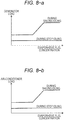
- FIG. 7 illustrates an example of rotational speed setting of the internal combustion engine during the sailing idling driving.
- the sailing idling driving by increasing the load of the internal combustion engine or increasing the rotational speed according to the evaporative fuel concentration, it is possible to actively control the purge flow rate. For example, when the evaporative fuel concentration is high as illustrated in FIG. 7-a , and when the idling rotational speed is increased, if the evaporative fuel concentration is high, it is possible to purge a more volatile fuel. Furthermore, by changing the idling rotational speed according to the vehicle speed, it is possible to purge the more evaporative fuel without making a driver feel strange.
- the idling rotational speed may be increased. According to this setting, by setting the idling rotational speed to the same speed as the engine brake, it is possible to increase the purge flow rate by simulating the rotational speed during engine braking.
- FIG. 8 illustrates an example of a method for setting a load of the internal combustion engine during the sailing idling driving.
- Fig. 8-a by increasing the generator load during sailing idling compared to vehicle stop idling, it is possible to increase the load of the internal combustion engine, and purge the more evaporative fuel.
- By setting the load according to the evaporative fuel concentration it is also possible to minimize deterioration of fuel efficiency due to the increase in the generator load.
- By accumulating generated power in the battery or causing another auxiliary device such as an air-conditioner described next to consume the power it is possible to minimize deterioration of the fuel efficiency.
- FIG. 8-a by increasing the generator load during sailing idling compared to vehicle stop idling, it is possible to increase the load of the internal combustion engine, and purge the more evaporative fuel.
- By setting the load according to the evaporative fuel concentration it is also possible to minimize deterioration of fuel efficiency due to the increase in the generator load.
- an upper limit and a lower limit are set to the generator load during sailing idling.
- the load is kept at the lower limit, and, when the evaporative fuel concentration is larger than the predetermined value, the load is kept at the upper limit.
- FIG. 9 illustrates another example of a method for setting the rotational speed of the internal combustion engine during sailing idling.
- the idling rotational speed is set according to the evaporative fuel concentration.
- the internal combustion engine control device engine controller 114 according to the present embodiment estimates or measures the evaporative fuel accumulation amount of the canister or the evaporative fuel volatilization amount of the fuel tank, and controls the idling rotational speed according to the estimation or the measurement value.
- the idling rotational speed may be lowered.
- FIG. 10 illustrates another example of a purge control time chart during the sailing idling.
- the evaporative fuel purge during the sailing idling driving is ended in response to a driver's acceleration request. It is necessary to synchronize the engine rotational speed with the wheel speed side rotational speed in order to connect the clutch during a transition from sailing to acceleration. Therefore, when the driver applies the accelerator at the time A, the purge valve is closed to reduce the evaporative fuel which becomes a disturbance for synchronization with the rotational speed. After the clutch is connected at the time B, the purge valve is opened again. Even when the more evaporative fuel is purged during the sailing driving, this control does not make combustion of the internal combustion engine unstable and the vehicle can transition to the acceleration state.
- FIG. 11 illustrates another example of the purge control time chart during the sailing idling.
- the control in case where the purge request is not met and canceled, and a transition is made from the sailing idling driving to the sailing stop driving will be described.
- the internal combustion engine control unit engine controller 114 according to the present embodiment performs sailing stop driving to stop fuel injection to the internal combustion engine 101 during coasting.
- the purge valve is opened. Consequently, it is possible to make the air-fuel ratio in the catalyst rich, and prevent emission of NOx to the atmosphere when the engine is started to accelerate.
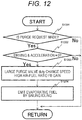
- FIG. 12 illustrates another example of a flowchart for realizing the present invention.
- the difference from FIG. 5 is step S1203, and the purge valve duty change rate and a gain of the air-fuel ratio feedback (air-fuel ratio FB) are made large compared to vehicle stop idling. That is, the internal combustion engine control unit (engine controller 114) increases an increase speed of the opening degree of the purge valve 106 compared to the idling driving while the vehicle stops. Alternatively, the internal combustion engine control unit (engine controller 114) increases the air-fuel ratio feedback response driving speed of the internal combustion engine 101 compared to the idling driving while the vehicle stops.
- FIG. 13 is another example of the purge control time chart during the sailing idling.
- a behavior during sailing idling is indicated by the solid line
- a behavior during vehicle stop idling is indicated by the dotted line
- these behaviors are overlaid and compared.
- During sailing idling it is possible to open the purge valve earlier compared to vehicle stop idling. This is because reflected heat from a ground is small a little during sailing compared to a time when the vehicle stops, and the fuel tank is cooled by a traveling wind and the amount of volatile fuel from the fuel tank is small. This control results in increasing and significantly fluctuating the internal combustion engine rotational speed during sailing idling compared to vehicle stop idling.
- FIG. 14 illustrates another example of a flowchart for realizing the present invention.
- the difference from FIG. 5 is that, when the purge concentration is the predetermined value or less in step S1402, the flow moves to step S1403 to ban evaporative fuel purge except for the sailing driving.
- FIG. 15 illustrates another example of the purge control time chart during the sailing idling.
- the purge valve drive duty and the purge air-fuel ratio correction coefficient become zero.
- the purge valve duty and the purge air-fuel ratio correction coefficient are controlled to purge the evaporative fuel.
- the purge valve 106 is closed.
- the internal combustion engine control unit (engine controller 114) according to the present embodiment bans evaporative fuel purge except for the sailing driving. According to the present configuration, when it is not necessary to quickly purge the evaporative fuel, by banning purge except for the sailing driving, it is possible to prevent deterioration of emission and drivability due to purge.
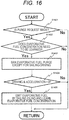
- FIG. 16 illustrates another example of a flowchart for realizing the present invention.
- the difference from FIG. 5 is that whether or not the evaporative fuel concentration needs to be learned is decided in step S1402, evaporative fuel purge except for the sailing driving is banned in step S1403 if necessary, and, when the sailing condition holds in step S1404, the evaporative fuel concentration is learned during the sailing idling driving in step S1405.
- FIG. 17 illustrates another example of the purge control time chart during the sailing idling.
- a great shift of the air-fuel ratio from the target air-fuel ratio while evaporative fuel purge is performed during driving at the time A triggers the evaporative fuel concentration learning request. For this reason, the evaporative fuel purge is banned in the interval from the time A to B (the purge valve duty is zero).
- the purge valve duty is zero.
- the air-fuel ratio is richer than the target air-fuel ratio at the time C. Therefore, the evaporative fuel concentration is corrected to the higher side and learned.
- the air-fuel ratio is near the target air-fuel ratio.
- a return of the air-fuel ratio correction coefficient to the purge ban interval (from the time A to the time B) before the sailing driving triggers ending of the evaporative fuel concentration learning to purge control during the sailing idling driving. According to this configuration, it is possible to learn the evaporative fuel concentration during the sailing driving, and prevent learning of the evaporative fuel concentration from deteriorating emission and drivability.
Landscapes
- Engineering & Computer Science (AREA)
- Chemical & Material Sciences (AREA)
- Combustion & Propulsion (AREA)
- Mechanical Engineering (AREA)
- General Engineering & Computer Science (AREA)
- Transportation (AREA)
- Automation & Control Theory (AREA)
- Supplying Secondary Fuel Or The Like To Fuel, Air Or Fuel-Air Mixtures (AREA)
- Control Of Vehicle Engines Or Engines For Specific Uses (AREA)
- Electrical Control Of Air Or Fuel Supplied To Internal-Combustion Engine (AREA)
Abstract
Description
- The present invention relates to a control device, and more particularly, relates to an evaporative fuel purge control technique of an internal combustion engine.
- Introduction of a low fuel consumption technique such as downsizing turbos and idling stop decreases an intake pipe negative pressure (pump loss) of an internal combustion engine, and results in difficulty in emitting (evaporative fuel purge) a volatile fuel (evaporative fuel) in a fuel tank by the negative pressure of the intake pipe of the internal combustion engine. Hence, PTL 1 discloses a method for stopping fuel injection to an internal combustion engine by way of idling stop, and performing evaporative fuel purge during a period in which an internal combustion engine rotational speed becomes a predetermined value or less to realize both of reduction of fuel consumption by way of idling stop and evaporative fuel purge.
- PTL 1: Japanese Patent Application Laid-Open No.
2012-26332 - However, according to PTL 1, it is only possible to perform evaporative fuel purge during a short period of time before the internal combustion engine actually stops after fuel supply to the internal combustion engine is stopped. There is a concern that, when the evaporative fuel is produced in the fuel tank or the evaporative fuel greatly accumulates in the canister, it is not possible to perform sufficient evaporative fuel purge and the volatile fuel leaks to an atmosphere. Furthermore, cases where vehicles hardly stop on expressways and in suburbs are not taken into account.
- The present invention intends to solve the above problem. An object of the present invention is to achieve sufficient evaporative fuel purge while achieving a fuel efficiency effect by stopping an engine by way of idling stop even when the evaporative fuel is frequently generated in a fuel tank or the evaporative fuel greatly accumulates in a canister.
- A control device includes: a purge control unit which controls a purge valve which emits a volatile fuel of a fuel tank or a canister to an intake pipe of an internal combustion engine; and a power transmission control unit which controls a power transmission mechanism between the internal combustion engine and a drive wheel, and, in a state where the power transmission control unit disconnects a clutch, and the vehicle is coasting, the purge control unit opens the evaporative fuel valve and purges the evaporative fuel to the intake pipe.
- By applying the present invention, it is possible to achieve sufficient evaporative fuel purge while achieving a fuel efficiency effect by stopping an engine by way of idling stop even when an evaporative fuel is frequently generated in a fuel tank frequently or the evaporative fuel greatly accumulates in a canister. In addition, by performing evaporative fuel purge during sailing driving, it is also possible to prevent deterioration of drivability and emission due to evaporative fuel purge.
-
- [
FIG. 1] FIG. 1 illustrates an example of a purge control system of an internal combustion engine. - [
FIG. 2] FIG. 2 illustrates an example of a purge control calculation block. - [
FIG. 3] FIG. 3 illustrates an example of a time chart during purge control. - [
FIG. 4] FIG. 4 illustrates an example of a power transmission control system which realizes the present invention. - [
FIG. 5] FIG. 5 illustrates an example of a flowchart for realizing the present invention. - [
FIG. 6] Fig. 6 illustrates an example of a purge control time chart during sailing idling. - [
FIG. 7-a] FIG. 7-a illustrates an example of a method for setting an internal combustion engine rotational speed during sailing idling. - [
FIG. 7-b] FIG. 7-b illustrates an example of a method for setting the internal combustion engine rotational speed during the sailing idling. - [
FIG. 8-a] FIG. 8-a illustrates an example of a method for setting an internal combustion engine load during the sailing idling. - [
FIG. 8-b] FIG. 8-b illustrates an example of the method for setting the internal combustion engine load during the sailing idling. - [
FIG. 9] FIG. 9 illustrates another example of the method for setting the internal combustion engine rotational speed during the sailing idling. - [
FIG. 10] FIG. 10 illustrates another example of a purge control time chart during the sailing idling. - [
FIG. 11] FIG. 11 illustrates another example of the purge control time chart during the sailing idling. - [
FIG. 12] FIG. 12 illustrates another example of a flowchart for realizing the present invention. - [
FIG. 13] FIG. 13 illustrates another example of the purge control time chart during sailing idling. - [
FIG. 14] FIG. 14 illustrates another example of a flowchart for realizing the present invention. - [
FIG. 15] FIG. 15 illustrates another example of the purge control time chart during the sailing idling. - [
FIG. 16] FIG. 16 illustrates another example of the flowchart for realizing the present invention. - [
FIG. 17] FIG. 17 illustrates another example of the purge control time chart during the sailing idling. - Hereinafter, embodiments of the present invention will be described in detail with reference to the drawings.
-
FIG. 1 is a view illustrating an example of a purge control system of an internal combustion engine. In order to prevent an evaporative fuel in afuel tank 104 from leaking to an atmosphere, anengine controller 114 controls an opening degree of apurge valve 106 and burn the evaporative fuel in aninternal combustion engine 101. Therefore, based on values of afuel level sensor 109 of thefuel tank 104, and a tank temperature/pressure sensor 113 which measures a temperature and a pressure in the fuel tank, theengine controller 114 estimates an evaporative fuel accumulation amount accumulated in acanister 112 during stop of the internal combustion engine or a volatile fuel amount generated in thefuel tank 109 during an operation of theinternal combustion engine 101, and, while an opening of athrottle 102 is small and a negative pressure is generated in anintake pipe 103, opens thepurge control valve 106 and purges the evaporative fuel to theintake pipe 103 via connectingpipes drain valve 108 is closed when leakage of an evaporative fuel from the fuel tank is detected. However, purge control is performed during the operation of the engine, and therefore thedrain valve 108 is almost in an opened state. A purge system can prevent the evaporative fuel generated in the fuel tank from leaking to the atmosphere. Next, a method for, when controlling an opening of thepurge valve 106 of a purge control system inFIG. 1 at a purge valve drive duty and purging the evaporative fuel, performing control to prevent an output of the internal combustion engine from becoming unstable will be described. -
FIG. 2 illustrates an example of a purge control calculation block. An evaporative fuelconcentration calculating unit 201 estimates the generation amount of evaporative fuel from the tank temperature and the remaining fuel amount, takes into account a correction coefficient of air-fuel ratio FB control when the purge valve is opened, and calculates a ratio of (evaporative fuel concentration) of the volatile fuel and air included in the purge emitted from the purge valve. A purgeduty calculating unit 202 calculates an evaporative fuel flow rate (purge flow rate) which contributes to a target evaporative fuel combustion from the evaporative fuel concentration and the throttle opening to prevent an output of the internal combustion engine and a combustion air-fuel ratio from fluctuating greatly. The purgeduty calculating unit 202 outputs the purge valve drive duty to prevent fluctuation of the purge flow rate from making the combustion of the internal combustion engine unstable. In addition, a purge air-fuel ratio correctioncoefficient calculating unit 203 makes correction to decrease an injector fuel injection amount by the amount that the combustion air-fuel ratio becomes rich by the evaporative fuel. Therefore, the purge air-fuel ratio correctioncoefficient calculating unit 203 calculates a purge air-fuel ratio correction coefficient (a rate of a decrease in the injector injection fuel) from the evaporative fuel concentration and the throttle opening. -
FIG. 3 illustrates an example of a time chart during purge control. The present embodiment describes a case where the throttle opening is constant, a load of the internal combustion engine does not changed, either, the evaporative fuel concentration is high (e.g., 40% or more), the purge valve is opened large at a time, and an engine stalls. At a time A, the purge valve drive duty is increased to start purging the evaporative fuel. When the fuel injection amount of the injector is decreased by the increase (approximately 30% at maximum) in the purge air-fuel ratio correction coefficient, the air-fuel ratio is kept at a stoichiometric, and it can be confirmed that the air-fuel ratio feedback control increases the air-fuel ratio correction coefficient and lowers the evaporative fuel concentration (e.g., when the air-fuel ratio correction coefficient changes by approximately 10% on average), the evaporative fuel concentration is reduced, and thepurge valve 106 is opened to control the purge flow rate to a predetermined value. Generally, the purge flow rate is determined by the throttle opening and the rotational speed of the internal combustion engine. Especially when the idling driving while the vehicle stops increases the purge flow rate, the evaporative fuel concentration is not constant, and therefore rotation fluctuates significantly. In the worst case, there is a risk of an accidental fire. Therefore, the present embodiment discloses a solution which uses the idling driving (sailing idling driving) during coasting/deceleration. -
FIG. 4 illustrates an example of a power transmission control system which performs sailing idling driving. The power generated by aninternal combustion engine 404 transmits to adrive wheel 403 via atorque converter 405, aclutch 406, and aCVT transmission 402. During the sailing idling driving, the power of theinternal combustion engine 404 does not transmit to thedrive wheel 403, and is used to coast or decelerate the vehicle. To transition to the sailing idling driving, atransmission controller 401 disconnects the clutch 406 while thedrive wheel 403 is rotating (driving), and theinternal combustion engine 404 is controlled to the idling rotational speed. Acompressor 408 of a generator and an air-conditioner is driven by abelt 407 even during the sailing driving. Therefore, by controlling these operating loads, it is possible to increase the internal combustion engine load during the sailing idling driving. The present embodiment will be described by using the CVT transmission. However, the present invention can be realized by using a transmission such as AMT or MT. -
FIG. 5 illustrates an example of a flowchart for realizing the present embodiment. In step S501, whether or not a purge request is made is decided. For example, whether or not the purge request is made is decided based on whether or not the evaporative fuel concentration calculated by theengine controller 114 inFIG. 1 is higher than a predetermined value. When the purge request is made, the flow moves to step S502. In step S502, in case of a sailing condition (e.g., the vehicle is driving and the accelerator opening is 0), the vehicle transitions to the coasting/decelerating state. That is, when the value of the accelerator opening sensor becomes the predetermined value or less as the sailing driving condition, it is desirable that the power transmission control unit disconnects the clutch 406 and the vehicle coasts. A sailing condition different from step S502 is a request from cruise control. More specifically, while the cruise control is executed, a vehicle acceleration/deceleration command may be used in place of the accelerator opening. For example, at a time when there is no acceleration command, it may be determined that the sailing condition holds. If the sailing condition holds in step S502, the flow moves to step S503. In step S503, thetransmission controller 401 inFIG. 4 performs control to transition to the sailing idling driving. The purge control as described inFIGS. 1 to 4 is performed. - As described above, the control device according to the present embodiment includes a purge control unit (engine controller 114) which controls the
purge valve 106 which emits a volatile fuel of thefuel tank 104 or thecanister 112 to theintake pipe 103 of theinternal combustion engine 101, and a power transmission control unit (transmission controller 401) which controls a power transmission mechanism (clutch 406) between theinternal combustion engine 101 and thedrive wheel 403. Further, in a state where the power transmission control unit disconnects the power transmission mechanism (the clutch 406 or a lock-up clutch of the torque converter 405) and the vehicle is coasting, the purge control unit (engine controller 114) opens thepurge valve 106 and performs control to emit the evaporative fuel to theintake pipe 103. This evaporative fuel is desirably controlled to be emitted to theintake pipe 103 in a state where the power transmission control unit disconnects the power transmission mechanism and the vehicle is coasting and when an evaporative fuel emission request is made. - A signal of the evaporative fuel emission request is desirably set to be sent when at least one of a volatile fuel concentration value in the fuel tank, a volatile fuel accumulation value of the canister and an evaporative fuel concentration value emitted from the purge valve becomes a predetermined value or more.
- In the present embodiment, the
engine controller 114 and thetransmission controller 401 are described as separate components. However, these controllers may be integrated. - In a state where the internal combustion engine control unit (engine controller 114) according to the present embodiment performs sailing idling driving for maintaining a rotational speed of the
internal combustion engine 101 at a predetermined rotational speed during the coasting, and the vehicle is coasting, the purge control unit (engine controller 114) opens thepurge valve 106 and performs control to emit the evaporative fuel to theintake pipe 103. It is desirable to set this predetermined rotational speed higher than the idling rotational speed while the vehicle stops. - As a result, when the vehicle coasts and decelerates, it is possible to emit the evaporative fuel, and realize both reduction of fuel consumption and purge the volatile fuel by way of idling stop. Next, the purge control according to the present invention will be described in more detail with reference to
FIGS. 6 to 11 . -
FIG. 6 illustrates an example of a purge control time chart during sailing idling. Here, a control method for starting purging the evaporative fuel during the sailing idling driving will be described. When the vehicle speed tends to decelerate and the evaporative fuel concentration is higher than the purge request threshold (e.g., 10%), it is decided that a purge request is made, and at a time when the accelerator opening becomes 0 and the sailing condition holds as at time A, a transition is made to the sailing idling driving. In this case, in order to quickly decrease the engine rotational speed to the idling rotational speed, the purge drive duty is set to 0 to close the purge valve is closed. At a time B when the purge stops, the fuel injection is stopped. Next, at a time C when combustion of the internal combustion engine stops and the rotational speed sufficiently lowers, the clutch is disconnected. The fuel is injected again to transition to the sailing idling driving. Subsequently, similar to description with reference toFIG. 3 , the evaporative fuel concentration is corrected according to the degree of increase in the air-fuel ratio correction coefficient, and the purge valve drive duty is controlled to purge the evaporative fuel. According to this control, a transition to the sailing idling is made by burning the purge fuel and transitioning to sailing idling. Consequently, it is possible to suppress emission deterioration due to the remaining purge fuel before the transition to sailing idling, and rotation fluctuation at the start of sailing idling driving. -
FIG. 7 illustrates an example of rotational speed setting of the internal combustion engine during the sailing idling driving. During the sailing idling driving, by increasing the load of the internal combustion engine or increasing the rotational speed according to the evaporative fuel concentration, it is possible to actively control the purge flow rate. For example, when the evaporative fuel concentration is high as illustrated inFIG. 7-a , and when the idling rotational speed is increased, if the evaporative fuel concentration is high, it is possible to purge a more volatile fuel. Furthermore, by changing the idling rotational speed according to the vehicle speed, it is possible to purge the more evaporative fuel without making a driver feel strange. From a viewpoint of setting the idling rotational speed which does not make the driver feel strange, when the deceleration is larger as illustrated inFIG. 7-b , the idling rotational speed may be increased. According to this setting, by setting the idling rotational speed to the same speed as the engine brake, it is possible to increase the purge flow rate by simulating the rotational speed during engine braking. -
FIG. 8 illustrates an example of a method for setting a load of the internal combustion engine during the sailing idling driving. InFig. 8-a , by increasing the generator load during sailing idling compared to vehicle stop idling, it is possible to increase the load of the internal combustion engine, and purge the more evaporative fuel. By setting the load according to the evaporative fuel concentration, it is also possible to minimize deterioration of fuel efficiency due to the increase in the generator load. By accumulating generated power in the battery or causing another auxiliary device such as an air-conditioner described next to consume the power, it is possible to minimize deterioration of the fuel efficiency. In addition, inFIG. 8-a , an upper limit and a lower limit are set to the generator load during sailing idling. When the evaporative fuel concentration is smaller than the predetermined value, the load is kept at the lower limit, and, when the evaporative fuel concentration is larger than the predetermined value, the load is kept at the upper limit. By changing the load upper limit, the lower limit and the predetermined value, it is possible to adjust fuel economy and adjust evaporative fuel purge. By setting a predetermined value for increasing the generator load to a lower evaporative fuel concentration, it is possible to purge the more evaporative fuel. InFIG. 8-b , by increasing an air-conditioning load during sailing idling compared to vehicle stop idling, it is possible to increase the load of the internal combustion engine, and purge the more evaporative fuel. In case of an electric air-conditioner compressor, it is possible to change the load of the internal combustion engine by increasing the above-mentioned generator load. In case of the mechanical air compressor, it is possible to change the load of the internal combustion engine by operating the compressor. -
FIG. 9 illustrates another example of a method for setting the rotational speed of the internal combustion engine during sailing idling. InFIG. 7-a , the idling rotational speed is set according to the evaporative fuel concentration. However, by setting the idle rotational speed based on the evaporative fuel accumulation amount of the canister and the fuel volatilization amount of the fuel tank instead of the evaporative fuel concentration, it is possible to realize the present invention. That is, the internal combustion engine control device (engine controller 114) according to the present embodiment estimates or measures the evaporative fuel accumulation amount of the canister or the evaporative fuel volatilization amount of the fuel tank, and controls the idling rotational speed according to the estimation or the measurement value. Here, by setting the idling rotational speed according to the vehicle speed instead of the deceleration illustrated inFIG. 7-b , it is possible to increase the purge flow rate without making the driver feel strange. Further, it is possible to adjust fuel consumption and purge according to the upper limit of the idling rotational speed. For example, to prioritize the improvement of fuel efficiency of the vehicle over the evaporative fuel purge, the upper limit of the rotational speed may be lowered. -
FIG. 10 illustrates another example of a purge control time chart during the sailing idling. Here, an example where the evaporative fuel purge during the sailing idling driving is ended in response to a driver's acceleration request will be described. It is necessary to synchronize the engine rotational speed with the wheel speed side rotational speed in order to connect the clutch during a transition from sailing to acceleration. Therefore, when the driver applies the accelerator at the time A, the purge valve is closed to reduce the evaporative fuel which becomes a disturbance for synchronization with the rotational speed. After the clutch is connected at the time B, the purge valve is opened again. Even when the more evaporative fuel is purged during the sailing driving, this control does not make combustion of the internal combustion engine unstable and the vehicle can transition to the acceleration state. -
FIG. 11 illustrates another example of the purge control time chart during the sailing idling. Here, the control in case where the purge request is not met and canceled, and a transition is made from the sailing idling driving to the sailing stop driving will be described. When the evaporative fuel concentration goes below the purge request threshold at the time A, and the purge request is canceled, the transition to the sailing stop driving for stopping the engine during sailing improves fuel efficiency. That is, the internal combustion engine control unit (engine controller 114) according to the present embodiment performs sailing stop driving to stop fuel injection to theinternal combustion engine 101 during coasting. In this case, until the time B when there is no negative pressure from stop of the fuel injection to theinternal combustion engine 101 to stop of rotation of the internal combustion engine, the purge valve is opened. Consequently, it is possible to make the air-fuel ratio in the catalyst rich, and prevent emission of NOx to the atmosphere when the engine is started to accelerate. -
FIG. 12 illustrates another example of a flowchart for realizing the present invention. The difference fromFIG. 5 is step S1203, and the purge valve duty change rate and a gain of the air-fuel ratio feedback (air-fuel ratio FB) are made large compared to vehicle stop idling. That is, the internal combustion engine control unit (engine controller 114) increases an increase speed of the opening degree of thepurge valve 106 compared to the idling driving while the vehicle stops. Alternatively, the internal combustion engine control unit (engine controller 114) increases the air-fuel ratio feedback response driving speed of theinternal combustion engine 101 compared to the idling driving while the vehicle stops. -
FIG. 13 is another example of the purge control time chart during the sailing idling. Here, a behavior during sailing idling is indicated by the solid line, a behavior during vehicle stop idling is indicated by the dotted line, and these behaviors are overlaid and compared. During sailing idling, it is possible to open the purge valve earlier compared to vehicle stop idling. This is because reflected heat from a ground is small a little during sailing compared to a time when the vehicle stops, and the fuel tank is cooled by a traveling wind and the amount of volatile fuel from the fuel tank is small. This control results in increasing and significantly fluctuating the internal combustion engine rotational speed during sailing idling compared to vehicle stop idling. It is possible to set the purge control duty change speed and the control gain of the air-fuel ratio control FB to such a degree that the driver does not notice during sailing. As a result, it is possible to purge the evaporative fuel during vehicle stop idling. -
FIG. 14 illustrates another example of a flowchart for realizing the present invention. The difference fromFIG. 5 is that, when the purge concentration is the predetermined value or less in step S1402, the flow moves to step S1403 to ban evaporative fuel purge except for the sailing driving. -
FIG. 15 illustrates another example of the purge control time chart during the sailing idling. At the time A when the evaporative fuel concentration goes below the purge ban decision threshold during driving (vehicle speed > 0), purging except for the sailing driving is banned. The purge valve drive duty and the purge air-fuel ratio correction coefficient become zero. Thereafter, when the sailing condition (vehicle speed> 0, and accelerator opening = 0) holds at the time B, and when the idling rotational speed is controlled at the time C, the purge valve duty and the purge air-fuel ratio correction coefficient are controlled to purge the evaporative fuel. When the sailing condition does not hold, thepurge valve 106 is closed. - When the volatile fuel concentration value in the fuel tank, the volatile fuel accumulation value of the canister or a value of the evaporative fuel concentration emitted from the purge valve becomes the predetermined value or less set higher than an evaporative fuel emission request, the internal combustion engine control unit (engine controller 114) according to the present embodiment bans evaporative fuel purge except for the sailing driving. According to the present configuration, when it is not necessary to quickly purge the evaporative fuel, by banning purge except for the sailing driving, it is possible to prevent deterioration of emission and drivability due to purge.
-
FIG. 16 illustrates another example of a flowchart for realizing the present invention. The difference fromFIG. 5 is that whether or not the evaporative fuel concentration needs to be learned is decided in step S1402, evaporative fuel purge except for the sailing driving is banned in step S1403 if necessary, and, when the sailing condition holds in step S1404, the evaporative fuel concentration is learned during the sailing idling driving in step S1405. -
FIG. 17 illustrates another example of the purge control time chart during the sailing idling. A great shift of the air-fuel ratio from the target air-fuel ratio while evaporative fuel purge is performed during driving at the time A triggers the evaporative fuel concentration learning request. For this reason, the evaporative fuel purge is banned in the interval from the time A to B (the purge valve duty is zero). From the time B when the sailing idling is started, the volatile fuel is purged, and the evaporative fuel concentration is learned. Here, the air-fuel ratio is richer than the target air-fuel ratio at the time C. Therefore, the evaporative fuel concentration is corrected to the higher side and learned. At a time D, the air-fuel ratio is near the target air-fuel ratio. A return of the air-fuel ratio correction coefficient to the purge ban interval (from the time A to the time B) before the sailing driving triggers ending of the evaporative fuel concentration learning to purge control during the sailing idling driving. According to this configuration, it is possible to learn the evaporative fuel concentration during the sailing driving, and prevent learning of the evaporative fuel concentration from deteriorating emission and drivability. -
- 101 internal combustion engine
- 102 throttle
- 103 intake pipe
- 104 fuel tank
- 106 purge valve
- 109 fuel level meter
- 112 canister
- 113 fuel tank pressure/temperature sensor
- 114 engine controller
- 401 transmission controller
- 402 CVT transmission
- 403 drive wheel
- 404 internal combustion engine
- 405 torque converter
- 406 clutch
- 407 belt
- 408 auxiliary machine (generator, and air-conditioner compressor)
Claims (16)
- A control device comprising:a purge control unit which controls a purge valve which emits a volatile fuel of a fuel tank or a canister to an intake pipe of an internal combustion engine; anda power transmission control unit which controls a power transmission mechanism between the internal combustion engine and a drive wheel,wherein, in a state where the power transmission control unit disconnects a clutch, and a vehicle is coasting, the purge control unit opens the purge valve and emits an evaporative fuel to the intake pipe.
- The control device according to claim 1, comprising an internal combustion engine control unit which performs sailing idling driving for maintaining a rotational speed of the internal combustion engine at a predetermined rotational speed during the coasting.
- The control device according to claim 1, comprising an internal combustion engine control unit which performs sailing stop driving for stopping fuel injection to the internal combustion engine during the coasting.
- The control device according to claim 1, wherein, in a state where the power transmission control unit disconnects the clutch, and the vehicle is coasting, and when an evaporative fuel emission request is made, the purge control unit opens the evaporative fuel valve and purges the evaporative fuel to the intake pipe.
- The control device according to claim 4, wherein a signal of the evaporative fuel emission request is sent when at least one of a volatile fuel concentration value in the fuel tank, a volatile fuel accumulation value of the canister and an evaporative fuel concentration value emitted from the purge valve becomes a predetermined value or more.
- The control device of the internal combustion engine according to claim 1, wherein, when a value of an accelerator opening sensor becomes a predetermined value or less, the power transmission control unit disconnects the clutch and the vehicle coasts.
- The control device according to claim 2, comprising an internal combustion engine control unit which sets the predetermined rotational speed higher than an idling rotational speed while the vehicle stops.
- The control device according to claim 2, comprising an internal combustion engine control unit which increases an auxiliary machine load of an air-conditioner output and a generator output during the sailing idling driving compared to idling while the vehicle stops.
- The control device according to claim 2, comprising an internal combustion engine control unit which estimates or measures an evaporative fuel accumulation amount of the canister or a fuel tank evaporative fuel volatilization amount, and controls an idling rotational speed according to the estimation value or the measurement value.
- The control device according to claim 2, comprising an internal combustion engine control unit which increases an increase speed of an opening degree of the purge valve compared to idling driving while the vehicle stops.
- The control device according to claim 10, comprising an internal combustion engine control unit which increases a feedback response speed of air-fuel ratio control of the internal combustion engine compared to the idling driving while the vehicle stops.
- The control device according to claim 2, comprising an internal combustion engine control unit which, when the purge request is not met, transitions from the sailing idling driving to sailing stop driving.
- The control device according to claim 12, comprising an internal combustion engine control unit which opens the purge valve until the internal combustion engine stops rotating after fuel injection to the internal combustion engine is stopped.
- The control device according to claim 1, comprising an internal combustion engine control unit which, when the sailing condition does not hold, closes the purge valve.
- The control device according to claim 1, comprising an internal combustion engine control unit which, when the volatile fuel concentration value in the fuel tank, the volatile fuel accumulation value of the canister or the evaporative fuel concentration value emitted from the purge valve becomes a predetermined value or less set higher than an evaporative fuel emission request, bans evaporative fuel purge except for sailing driving.
- The control device according to claim 1, comprising an internal combustion engine control unit which, when an evaporative fuel concentration learning request is met, bans evaporative fuel purge except for sailing driving, and learns an evaporative fuel concentration during sailing idling driving.
Applications Claiming Priority (2)
| Application Number | Priority Date | Filing Date | Title |
|---|---|---|---|
| JP2015179054A JP6506665B2 (en) | 2015-09-11 | 2015-09-11 | Control device |
| PCT/JP2016/072098 WO2017043208A1 (en) | 2015-09-11 | 2016-07-28 | Control device |
Publications (3)
| Publication Number | Publication Date |
|---|---|
| EP3348823A1 true EP3348823A1 (en) | 2018-07-18 |
| EP3348823A4 EP3348823A4 (en) | 2019-05-15 |
| EP3348823B1 EP3348823B1 (en) | 2020-06-24 |
Family
ID=58240765
Family Applications (1)
| Application Number | Title | Priority Date | Filing Date |
|---|---|---|---|
| EP16844072.5A Active EP3348823B1 (en) | 2015-09-11 | 2016-07-28 | Control device |
Country Status (5)
| Country | Link |
|---|---|
| US (1) | US10465619B2 (en) |
| EP (1) | EP3348823B1 (en) |
| JP (1) | JP6506665B2 (en) |
| CN (1) | CN107949696B (en) |
| WO (1) | WO2017043208A1 (en) |
Families Citing this family (6)
| Publication number | Priority date | Publication date | Assignee | Title |
|---|---|---|---|---|
| DE102017102367B4 (en) * | 2017-02-07 | 2023-10-12 | Volkswagen Aktiengesellschaft | Method for increasing the tank ventilation flush quantity by completely suppressing the injection of at least one cylinder |
| CN111033025B (en) * | 2017-08-29 | 2022-07-15 | 全耐塑料高级创新研究公司 | System and method for changing the opening speed of a fuel tank valve |
| JP2020016225A (en) * | 2018-07-27 | 2020-01-30 | 愛三工業株式会社 | Evaporative fuel processing device |
| KR20200069733A (en) * | 2018-12-07 | 2020-06-17 | 현대자동차주식회사 | Purge control method for fuel evaporation gas |
| CN112460637A (en) * | 2020-10-27 | 2021-03-09 | 中国船舶重工集团公司第七0三研究所 | Dual-fuel gas turbine bleed purging system |
| CN115217644B (en) * | 2021-05-10 | 2023-11-17 | 广州汽车集团股份有限公司 | Control method of automobile evaporation and emission device |
Family Cites Families (12)
| Publication number | Priority date | Publication date | Assignee | Title |
|---|---|---|---|---|
| JPH04358756A (en) * | 1991-03-29 | 1992-12-11 | Mazda Motor Corp | Evaporated fuel control device for engine |
| JPH07180621A (en) * | 1993-12-22 | 1995-07-18 | Nissan Motor Co Ltd | Evaporative fuel treatment system for spark ignition type internal combustion engine |
| JPH07229451A (en) * | 1994-02-18 | 1995-08-29 | Nippondenso Co Ltd | Fuel feed quantity control device of internal combustion engine |
| JP3761666B2 (en) * | 1997-02-26 | 2006-03-29 | 本田技研工業株式会社 | Evaporative fuel emission prevention device for internal combustion engine |
| JP2001098994A (en) * | 1999-09-30 | 2001-04-10 | Mazda Motor Corp | Vehicle control device and engine control device |
| JP4513975B2 (en) * | 2005-07-01 | 2010-07-28 | スズキ株式会社 | Purge control device |
| JP4687508B2 (en) * | 2006-03-06 | 2011-05-25 | 日産自動車株式会社 | Evaporated fuel processing apparatus and evaporated fuel processing method |
| KR100936983B1 (en) * | 2008-05-07 | 2010-01-15 | 현대자동차주식회사 | Exhaust gas control system and method |
| JP2009281281A (en) * | 2008-05-22 | 2009-12-03 | Honda Motor Co Ltd | Control device for vehicle |
| JP2012026332A (en) | 2010-07-22 | 2012-02-09 | Denso Corp | Control device for internal combustion engine |
| WO2012039047A1 (en) * | 2010-09-23 | 2012-03-29 | トヨタ自動車 株式会社 | Control device for internal combustion engine |
| US8892289B2 (en) * | 2012-05-04 | 2014-11-18 | Ford Global Technologies, Llc | Methods and systems for operating a vehicle driveline |
-
2015
- 2015-09-11 JP JP2015179054A patent/JP6506665B2/en not_active Expired - Fee Related
-
2016
- 2016-07-28 US US15/737,495 patent/US10465619B2/en not_active Expired - Fee Related
- 2016-07-28 WO PCT/JP2016/072098 patent/WO2017043208A1/en not_active Ceased
- 2016-07-28 CN CN201680050236.3A patent/CN107949696B/en not_active Expired - Fee Related
- 2016-07-28 EP EP16844072.5A patent/EP3348823B1/en active Active
Also Published As
| Publication number | Publication date |
|---|---|
| WO2017043208A1 (en) | 2017-03-16 |
| US20180171896A1 (en) | 2018-06-21 |
| EP3348823A4 (en) | 2019-05-15 |
| EP3348823B1 (en) | 2020-06-24 |
| JP2017053294A (en) | 2017-03-16 |
| CN107949696A (en) | 2018-04-20 |
| JP6506665B2 (en) | 2019-04-24 |
| CN107949696B (en) | 2020-04-03 |
| US10465619B2 (en) | 2019-11-05 |
Similar Documents
| Publication | Publication Date | Title |
|---|---|---|
| EP3348823B1 (en) | Control device | |
| US10047665B2 (en) | Methods and systems for boost control | |
| RU2671255C1 (en) | Method and system for delivering torque to a power take-off shaft device | |
| US9969397B2 (en) | Control device for vehicle | |
| CN110573716B (en) | Deceleration cylinder cutoff in hybrid vehicle | |
| CN105121242B (en) | Method for operating a hybrid vehicle | |
| JP2009180231A (en) | Powertrain control device | |
| CN106640394A (en) | Methods and systems for improving boost response | |
| US20180362044A1 (en) | Vehicle control device | |
| US9643610B2 (en) | Method and arrangement for controlling an automatic transmission unit | |
| US11248543B2 (en) | Vaporized-fuel treating apparatus | |
| JP2008179179A (en) | Powertrain control device | |
| US20130040780A1 (en) | Method for controlling the starting of a motor vehicle | |
| JP4784574B2 (en) | VEHICLE CONTROL DEVICE, CONTROL METHOD, PROGRAM FOR MAKING THE METHOD TO COMPUTER COMPUTER, AND RECORDING MEDIUM CONTAINING THE PROGRAM | |
| EP1953057A2 (en) | Control apparatus and control method for vehicle | |
| US11433870B2 (en) | Method for control and/or regulation of a hybrid powertrain of a motor vehicle with an exhaust gas recirculation system | |
| JP4274263B2 (en) | Vehicle control device | |
| JP5640639B2 (en) | Control device for internal combustion engine | |
| JP2014080934A (en) | Engine control device | |
| US10801435B2 (en) | Engine air-fuel ratio control device | |
| JP2626394B2 (en) | Slip control device for vehicle direct coupling clutch | |
| JP5601148B2 (en) | Control device for hybrid vehicle | |
| JP2012002193A (en) | Vehicle control device | |
| JP2002349324A (en) | Control device for internal combustion engine |
Legal Events
| Date | Code | Title | Description |
|---|---|---|---|
| STAA | Information on the status of an ep patent application or granted ep patent |
Free format text: STATUS: THE INTERNATIONAL PUBLICATION HAS BEEN MADE |
|
| PUAI | Public reference made under article 153(3) epc to a published international application that has entered the european phase |
Free format text: ORIGINAL CODE: 0009012 |
|
| STAA | Information on the status of an ep patent application or granted ep patent |
Free format text: STATUS: REQUEST FOR EXAMINATION WAS MADE |
|
| 17P | Request for examination filed |
Effective date: 20180411 |
|
| AK | Designated contracting states |
Kind code of ref document: A1 Designated state(s): AL AT BE BG CH CY CZ DE DK EE ES FI FR GB GR HR HU IE IS IT LI LT LU LV MC MK MT NL NO PL PT RO RS SE SI SK SM TR |
|
| AX | Request for extension of the european patent |
Extension state: BA ME |
|
| DAV | Request for validation of the european patent (deleted) | ||
| DAX | Request for extension of the european patent (deleted) | ||
| A4 | Supplementary search report drawn up and despatched |
Effective date: 20190412 |
|
| RIC1 | Information provided on ipc code assigned before grant |
Ipc: F02D 41/02 20060101ALI20190408BHEP Ipc: B60W 10/06 20060101ALI20190408BHEP Ipc: F02M 25/08 20060101AFI20190408BHEP Ipc: F02D 41/14 20060101ALI20190408BHEP Ipc: B60W 30/18 20120101ALI20190408BHEP Ipc: F02D 41/12 20060101ALI20190408BHEP Ipc: F02D 29/04 20060101ALI20190408BHEP Ipc: B60W 10/02 20060101ALI20190408BHEP Ipc: F02D 41/08 20060101ALI20190408BHEP Ipc: F02D 29/02 20060101ALI20190408BHEP Ipc: F02D 41/00 20060101ALI20190408BHEP Ipc: F02D 29/06 20060101ALI20190408BHEP Ipc: F02D 41/04 20060101ALI20190408BHEP |
|
| GRAP | Despatch of communication of intention to grant a patent |
Free format text: ORIGINAL CODE: EPIDOSNIGR1 |
|
| STAA | Information on the status of an ep patent application or granted ep patent |
Free format text: STATUS: GRANT OF PATENT IS INTENDED |
|
| INTG | Intention to grant announced |
Effective date: 20200109 |
|
| GRAS | Grant fee paid |
Free format text: ORIGINAL CODE: EPIDOSNIGR3 |
|
| GRAA | (expected) grant |
Free format text: ORIGINAL CODE: 0009210 |
|
| STAA | Information on the status of an ep patent application or granted ep patent |
Free format text: STATUS: THE PATENT HAS BEEN GRANTED |
|
| AK | Designated contracting states |
Kind code of ref document: B1 Designated state(s): AL AT BE BG CH CY CZ DE DK EE ES FI FR GB GR HR HU IE IS IT LI LT LU LV MC MK MT NL NO PL PT RO RS SE SI SK SM TR |
|
| REG | Reference to a national code |
Ref country code: GB Ref legal event code: FG4D |
|
| REG | Reference to a national code |
Ref country code: CH Ref legal event code: EP |
|
| REG | Reference to a national code |
Ref country code: DE Ref legal event code: R096 Ref document number: 602016038889 Country of ref document: DE |
|
| REG | Reference to a national code |
Ref country code: AT Ref legal event code: REF Ref document number: 1284122 Country of ref document: AT Kind code of ref document: T Effective date: 20200715 |
|
| REG | Reference to a national code |
Ref country code: IE Ref legal event code: FG4D |
|
| PG25 | Lapsed in a contracting state [announced via postgrant information from national office to epo] |
Ref country code: GR Free format text: LAPSE BECAUSE OF FAILURE TO SUBMIT A TRANSLATION OF THE DESCRIPTION OR TO PAY THE FEE WITHIN THE PRESCRIBED TIME-LIMIT Effective date: 20200925 Ref country code: NO Free format text: LAPSE BECAUSE OF FAILURE TO SUBMIT A TRANSLATION OF THE DESCRIPTION OR TO PAY THE FEE WITHIN THE PRESCRIBED TIME-LIMIT Effective date: 20200924 Ref country code: FI Free format text: LAPSE BECAUSE OF FAILURE TO SUBMIT A TRANSLATION OF THE DESCRIPTION OR TO PAY THE FEE WITHIN THE PRESCRIBED TIME-LIMIT Effective date: 20200624 Ref country code: SE Free format text: LAPSE BECAUSE OF FAILURE TO SUBMIT A TRANSLATION OF THE DESCRIPTION OR TO PAY THE FEE WITHIN THE PRESCRIBED TIME-LIMIT Effective date: 20200624 Ref country code: LT Free format text: LAPSE BECAUSE OF FAILURE TO SUBMIT A TRANSLATION OF THE DESCRIPTION OR TO PAY THE FEE WITHIN THE PRESCRIBED TIME-LIMIT Effective date: 20200624 |
|
| REG | Reference to a national code |
Ref country code: LT Ref legal event code: MG4D |
|
| PG25 | Lapsed in a contracting state [announced via postgrant information from national office to epo] |
Ref country code: BG Free format text: LAPSE BECAUSE OF FAILURE TO SUBMIT A TRANSLATION OF THE DESCRIPTION OR TO PAY THE FEE WITHIN THE PRESCRIBED TIME-LIMIT Effective date: 20200924 Ref country code: RS Free format text: LAPSE BECAUSE OF FAILURE TO SUBMIT A TRANSLATION OF THE DESCRIPTION OR TO PAY THE FEE WITHIN THE PRESCRIBED TIME-LIMIT Effective date: 20200624 Ref country code: LV Free format text: LAPSE BECAUSE OF FAILURE TO SUBMIT A TRANSLATION OF THE DESCRIPTION OR TO PAY THE FEE WITHIN THE PRESCRIBED TIME-LIMIT Effective date: 20200624 Ref country code: HR Free format text: LAPSE BECAUSE OF FAILURE TO SUBMIT A TRANSLATION OF THE DESCRIPTION OR TO PAY THE FEE WITHIN THE PRESCRIBED TIME-LIMIT Effective date: 20200624 |
|
| REG | Reference to a national code |
Ref country code: NL Ref legal event code: MP Effective date: 20200624 |
|
| REG | Reference to a national code |
Ref country code: AT Ref legal event code: MK05 Ref document number: 1284122 Country of ref document: AT Kind code of ref document: T Effective date: 20200624 |
|
| PG25 | Lapsed in a contracting state [announced via postgrant information from national office to epo] |
Ref country code: NL Free format text: LAPSE BECAUSE OF FAILURE TO SUBMIT A TRANSLATION OF THE DESCRIPTION OR TO PAY THE FEE WITHIN THE PRESCRIBED TIME-LIMIT Effective date: 20200624 Ref country code: AL Free format text: LAPSE BECAUSE OF FAILURE TO SUBMIT A TRANSLATION OF THE DESCRIPTION OR TO PAY THE FEE WITHIN THE PRESCRIBED TIME-LIMIT Effective date: 20200624 |
|
| PG25 | Lapsed in a contracting state [announced via postgrant information from national office to epo] |
Ref country code: AT Free format text: LAPSE BECAUSE OF FAILURE TO SUBMIT A TRANSLATION OF THE DESCRIPTION OR TO PAY THE FEE WITHIN THE PRESCRIBED TIME-LIMIT Effective date: 20200624 Ref country code: EE Free format text: LAPSE BECAUSE OF FAILURE TO SUBMIT A TRANSLATION OF THE DESCRIPTION OR TO PAY THE FEE WITHIN THE PRESCRIBED TIME-LIMIT Effective date: 20200624 Ref country code: SM Free format text: LAPSE BECAUSE OF FAILURE TO SUBMIT A TRANSLATION OF THE DESCRIPTION OR TO PAY THE FEE WITHIN THE PRESCRIBED TIME-LIMIT Effective date: 20200624 Ref country code: CZ Free format text: LAPSE BECAUSE OF FAILURE TO SUBMIT A TRANSLATION OF THE DESCRIPTION OR TO PAY THE FEE WITHIN THE PRESCRIBED TIME-LIMIT Effective date: 20200624 Ref country code: RO Free format text: LAPSE BECAUSE OF FAILURE TO SUBMIT A TRANSLATION OF THE DESCRIPTION OR TO PAY THE FEE WITHIN THE PRESCRIBED TIME-LIMIT Effective date: 20200624 Ref country code: IT Free format text: LAPSE BECAUSE OF FAILURE TO SUBMIT A TRANSLATION OF THE DESCRIPTION OR TO PAY THE FEE WITHIN THE PRESCRIBED TIME-LIMIT Effective date: 20200624 Ref country code: PT Free format text: LAPSE BECAUSE OF FAILURE TO SUBMIT A TRANSLATION OF THE DESCRIPTION OR TO PAY THE FEE WITHIN THE PRESCRIBED TIME-LIMIT Effective date: 20201026 Ref country code: ES Free format text: LAPSE BECAUSE OF FAILURE TO SUBMIT A TRANSLATION OF THE DESCRIPTION OR TO PAY THE FEE WITHIN THE PRESCRIBED TIME-LIMIT Effective date: 20200624 |
|
| PG25 | Lapsed in a contracting state [announced via postgrant information from national office to epo] |
Ref country code: PL Free format text: LAPSE BECAUSE OF FAILURE TO SUBMIT A TRANSLATION OF THE DESCRIPTION OR TO PAY THE FEE WITHIN THE PRESCRIBED TIME-LIMIT Effective date: 20200624 Ref country code: SK Free format text: LAPSE BECAUSE OF FAILURE TO SUBMIT A TRANSLATION OF THE DESCRIPTION OR TO PAY THE FEE WITHIN THE PRESCRIBED TIME-LIMIT Effective date: 20200624 Ref country code: IS Free format text: LAPSE BECAUSE OF FAILURE TO SUBMIT A TRANSLATION OF THE DESCRIPTION OR TO PAY THE FEE WITHIN THE PRESCRIBED TIME-LIMIT Effective date: 20201024 |
|
| REG | Reference to a national code |
Ref country code: CH Ref legal event code: PL |
|
| REG | Reference to a national code |
Ref country code: DE Ref legal event code: R082 Ref document number: 602016038889 Country of ref document: DE Representative=s name: MERH-IP MATIAS ERNY REICHL HOFFMANN PATENTANWA, DE Ref country code: DE Ref legal event code: R081 Ref document number: 602016038889 Country of ref document: DE Owner name: HITACHI ASTEMO, LTD., HITACHINAKA-SHI, JP Free format text: FORMER OWNER: HITACHI AUTOMOTIVE SYSTEMS, LTD., HITACHINAKA-SHI, IBARAKI, JP |
|
| REG | Reference to a national code |
Ref country code: DE Ref legal event code: R097 Ref document number: 602016038889 Country of ref document: DE |
|
| PG25 | Lapsed in a contracting state [announced via postgrant information from national office to epo] |
Ref country code: MC Free format text: LAPSE BECAUSE OF FAILURE TO SUBMIT A TRANSLATION OF THE DESCRIPTION OR TO PAY THE FEE WITHIN THE PRESCRIBED TIME-LIMIT Effective date: 20200624 |
|
| REG | Reference to a national code |
Ref country code: BE Ref legal event code: MM Effective date: 20200731 |
|
| PG25 | Lapsed in a contracting state [announced via postgrant information from national office to epo] |
Ref country code: DK Free format text: LAPSE BECAUSE OF FAILURE TO SUBMIT A TRANSLATION OF THE DESCRIPTION OR TO PAY THE FEE WITHIN THE PRESCRIBED TIME-LIMIT Effective date: 20200624 Ref country code: CH Free format text: LAPSE BECAUSE OF NON-PAYMENT OF DUE FEES Effective date: 20200731 Ref country code: LI Free format text: LAPSE BECAUSE OF NON-PAYMENT OF DUE FEES Effective date: 20200731 Ref country code: LU Free format text: LAPSE BECAUSE OF NON-PAYMENT OF DUE FEES Effective date: 20200728 |
|
| PLBE | No opposition filed within time limit |
Free format text: ORIGINAL CODE: 0009261 |
|
| STAA | Information on the status of an ep patent application or granted ep patent |
Free format text: STATUS: NO OPPOSITION FILED WITHIN TIME LIMIT |
|
| GBPC | Gb: european patent ceased through non-payment of renewal fee |
Effective date: 20200924 |
|
| PG25 | Lapsed in a contracting state [announced via postgrant information from national office to epo] |
Ref country code: BE Free format text: LAPSE BECAUSE OF NON-PAYMENT OF DUE FEES Effective date: 20200731 |
|
| 26N | No opposition filed |
Effective date: 20210325 |
|
| PG25 | Lapsed in a contracting state [announced via postgrant information from national office to epo] |
Ref country code: FR Free format text: LAPSE BECAUSE OF NON-PAYMENT OF DUE FEES Effective date: 20200824 |
|
| PG25 | Lapsed in a contracting state [announced via postgrant information from national office to epo] |
Ref country code: GB Free format text: LAPSE BECAUSE OF NON-PAYMENT OF DUE FEES Effective date: 20200924 Ref country code: IE Free format text: LAPSE BECAUSE OF NON-PAYMENT OF DUE FEES Effective date: 20200728 Ref country code: SI Free format text: LAPSE BECAUSE OF FAILURE TO SUBMIT A TRANSLATION OF THE DESCRIPTION OR TO PAY THE FEE WITHIN THE PRESCRIBED TIME-LIMIT Effective date: 20200624 |
|
| PG25 | Lapsed in a contracting state [announced via postgrant information from national office to epo] |
Ref country code: TR Free format text: LAPSE BECAUSE OF FAILURE TO SUBMIT A TRANSLATION OF THE DESCRIPTION OR TO PAY THE FEE WITHIN THE PRESCRIBED TIME-LIMIT Effective date: 20200624 Ref country code: MT Free format text: LAPSE BECAUSE OF FAILURE TO SUBMIT A TRANSLATION OF THE DESCRIPTION OR TO PAY THE FEE WITHIN THE PRESCRIBED TIME-LIMIT Effective date: 20200624 Ref country code: CY Free format text: LAPSE BECAUSE OF FAILURE TO SUBMIT A TRANSLATION OF THE DESCRIPTION OR TO PAY THE FEE WITHIN THE PRESCRIBED TIME-LIMIT Effective date: 20200624 |
|
| PG25 | Lapsed in a contracting state [announced via postgrant information from national office to epo] |
Ref country code: MK Free format text: LAPSE BECAUSE OF FAILURE TO SUBMIT A TRANSLATION OF THE DESCRIPTION OR TO PAY THE FEE WITHIN THE PRESCRIBED TIME-LIMIT Effective date: 20200624 |
|
| PGFP | Annual fee paid to national office [announced via postgrant information from national office to epo] |
Ref country code: DE Payment date: 20220531 Year of fee payment: 7 |
|
| REG | Reference to a national code |
Ref country code: DE Ref legal event code: R119 Ref document number: 602016038889 Country of ref document: DE |
|
| PG25 | Lapsed in a contracting state [announced via postgrant information from national office to epo] |
Ref country code: DE Free format text: LAPSE BECAUSE OF NON-PAYMENT OF DUE FEES Effective date: 20240201 |