EP3348797A1 - Flexible band electrical component mounts and methods - Google Patents
Flexible band electrical component mounts and methods Download PDFInfo
- Publication number
- EP3348797A1 EP3348797A1 EP17204155.0A EP17204155A EP3348797A1 EP 3348797 A1 EP3348797 A1 EP 3348797A1 EP 17204155 A EP17204155 A EP 17204155A EP 3348797 A1 EP3348797 A1 EP 3348797A1
- Authority
- EP
- European Patent Office
- Prior art keywords
- flexible band
- electrical component
- aircraft propulsor
- electrical components
- aircraft
- Prior art date
- Legal status (The legal status is an assumption and is not a legal conclusion. Google has not performed a legal analysis and makes no representation as to the accuracy of the status listed.)
- Granted
Links
Images



Classifications
-
- F—MECHANICAL ENGINEERING; LIGHTING; HEATING; WEAPONS; BLASTING
- F01—MACHINES OR ENGINES IN GENERAL; ENGINE PLANTS IN GENERAL; STEAM ENGINES
- F01D—NON-POSITIVE DISPLACEMENT MACHINES OR ENGINES, e.g. STEAM TURBINES
- F01D21/00—Shutting-down of machines or engines, e.g. in emergency; Regulating, controlling, or safety means not otherwise provided for
- F01D21/003—Arrangements for testing or measuring
-
- B—PERFORMING OPERATIONS; TRANSPORTING
- B64—AIRCRAFT; AVIATION; COSMONAUTICS
- B64D—EQUIPMENT FOR FITTING IN OR TO AIRCRAFT; FLIGHT SUITS; PARACHUTES; ARRANGEMENT OR MOUNTING OF POWER PLANTS OR PROPULSION TRANSMISSIONS IN AIRCRAFT
- B64D47/00—Equipment not otherwise provided for
-
- B—PERFORMING OPERATIONS; TRANSPORTING
- B64—AIRCRAFT; AVIATION; COSMONAUTICS
- B64D—EQUIPMENT FOR FITTING IN OR TO AIRCRAFT; FLIGHT SUITS; PARACHUTES; ARRANGEMENT OR MOUNTING OF POWER PLANTS OR PROPULSION TRANSMISSIONS IN AIRCRAFT
- B64D29/00—Power-plant nacelles, fairings or cowlings
-
- F—MECHANICAL ENGINEERING; LIGHTING; HEATING; WEAPONS; BLASTING
- F01—MACHINES OR ENGINES IN GENERAL; ENGINE PLANTS IN GENERAL; STEAM ENGINES
- F01D—NON-POSITIVE DISPLACEMENT MACHINES OR ENGINES, e.g. STEAM TURBINES
- F01D17/00—Regulating or controlling by varying flow
- F01D17/02—Arrangement of sensing elements
-
- F—MECHANICAL ENGINEERING; LIGHTING; HEATING; WEAPONS; BLASTING
- F01—MACHINES OR ENGINES IN GENERAL; ENGINE PLANTS IN GENERAL; STEAM ENGINES
- F01D—NON-POSITIVE DISPLACEMENT MACHINES OR ENGINES, e.g. STEAM TURBINES
- F01D25/00—Component parts, details, or accessories, not provided for in, or of interest apart from, other groups
- F01D25/24—Casings; Casing parts, e.g. diaphragms, casing fastenings
-
- F—MECHANICAL ENGINEERING; LIGHTING; HEATING; WEAPONS; BLASTING
- F01—MACHINES OR ENGINES IN GENERAL; ENGINE PLANTS IN GENERAL; STEAM ENGINES
- F01D—NON-POSITIVE DISPLACEMENT MACHINES OR ENGINES, e.g. STEAM TURBINES
- F01D25/00—Component parts, details, or accessories, not provided for in, or of interest apart from, other groups
- F01D25/28—Supporting or mounting arrangements, e.g. for turbine casing
-
- H—ELECTRICITY
- H05—ELECTRIC TECHNIQUES NOT OTHERWISE PROVIDED FOR
- H05K—PRINTED CIRCUITS; CASINGS OR CONSTRUCTIONAL DETAILS OF ELECTRIC APPARATUS; MANUFACTURE OF ASSEMBLAGES OF ELECTRICAL COMPONENTS
- H05K7/00—Constructional details common to different types of electric apparatus
- H05K7/02—Arrangements of circuit components or wiring on supporting structure
- H05K7/12—Resilient or clamping means for holding component to structure
-
- F—MECHANICAL ENGINEERING; LIGHTING; HEATING; WEAPONS; BLASTING
- F05—INDEXING SCHEMES RELATING TO ENGINES OR PUMPS IN VARIOUS SUBCLASSES OF CLASSES F01-F04
- F05D—INDEXING SCHEME FOR ASPECTS RELATING TO NON-POSITIVE-DISPLACEMENT MACHINES OR ENGINES, GAS-TURBINES OR JET-PROPULSION PLANTS
- F05D2220/00—Application
- F05D2220/30—Application in turbines
- F05D2220/32—Application in turbines in gas turbines
- F05D2220/323—Application in turbines in gas turbines for aircraft propulsion, e.g. jet engines
-
- F—MECHANICAL ENGINEERING; LIGHTING; HEATING; WEAPONS; BLASTING
- F05—INDEXING SCHEMES RELATING TO ENGINES OR PUMPS IN VARIOUS SUBCLASSES OF CLASSES F01-F04
- F05D—INDEXING SCHEME FOR ASPECTS RELATING TO NON-POSITIVE-DISPLACEMENT MACHINES OR ENGINES, GAS-TURBINES OR JET-PROPULSION PLANTS
- F05D2260/00—Function
- F05D2260/83—Testing, e.g. methods, components or tools therefor
Definitions
- Instrumentation is needed for monitoring of aircraft propulsor conditions during operation and/or during testing.
- instrumentation is generally mounted as small clusters on individual brackets.
- individual brackets are generally mounted on inlet bulkheads.
- space on inlet bulkheads of aircraft propulsors is generally limited and accordingly limit the amount of instruments that can be used at any one time.
- the fan 136 intakes and/or energizes air flowing into the nacelle 102, such as in an airflow direction 140A. Air that flows into the nacelle 102 via airflow direction 140A may flow through various internal flow paths within the nacelle 102.
- the electrical components 220A-C may be any electrical component.
- the electrical components 220A-C may be configured to determine a parameter of the aircraft propulsor 100.
- electrical components 220A-C may be, for example, transducers such as accelerometers (e.g., load cells, air flow sensors, potentiometers, and other transducers) as well as gyroscopes and/or other such sensors.
- Fig. 4 illustrates a perspective view of a further example of a flexible band electrical component mount in accordance with the disclosure.
- the aircraft propulsor 100 shown in Fig. 4 also includes a bulkhead 206 that includes pass-throughs 208A and 208B.
- Fig. 4 illustrates flexible band electrical component mounts 416A and 416B that includes flexible bands 430A and 430B, respectively, each with one or more electrical component openings (e.g., electrical component openings 432A-C and 442A-C) configured to hold one or more electrical components.
- electrical component openings e.g., electrical component openings 432A-C and 442A-C
- the flexible band 430A and 430B are the same band, connected, or different bands, they may be wrapped a plurality of times around itself, around one or another of the flexible bands 430A and/or 430B, and/or another such flexible band. Accordingly, the flexible bands may be "layered" as needed to hold the required number of electrical components.
- One portion of the flexible band may then be coupled to another portion of the flexible band in block 606. Coupling the portions of the flexible band together may hold the flexible band against the portion of the aircraft propulsor.
- the portions may be portions of the same flexible band, but in other examples, the portions may be portions of two or more different flexible bands.
- a strap may be wrapped around the flexible band or plurality of flexible bands to hold the one or more bands around the portion of the aircraft propulsor.
- wires of the electrical components may be organized.
- one or more wire organizers may be used to hold a plurality of wires to organize the wires.
- the wire organizers may hold the wires to aid in threading the wires through one or more pass-throughs located on a bulkhead of the aircraft propulsor.
- the electrical components may then electrically connect to one or more testing modules to, for example, deliver data to such testing modules.
- the testing modules may be located on the aircraft propulsor and/or may be remotely located and data may be delivered via, for example, one or more data connections.
Landscapes
- Engineering & Computer Science (AREA)
- Mechanical Engineering (AREA)
- General Engineering & Computer Science (AREA)
- Aviation & Aerospace Engineering (AREA)
- Microelectronics & Electronic Packaging (AREA)
- Clamps And Clips (AREA)
- Laminated Bodies (AREA)
- Installation Of Indoor Wiring (AREA)
- Testing Of Devices, Machine Parts, Or Other Structures Thereof (AREA)
Abstract
Description
- The disclosure relates generally to aircraft and more specifically to instrumentation mounting for aircraft propulsor testing.
- Instrumentation is needed for monitoring of aircraft propulsor conditions during operation and/or during testing. When a plurality of instruments are required, as on all modern aircraft propulsors, such instrumentation is generally mounted as small clusters on individual brackets. Such individual brackets are generally mounted on inlet bulkheads. However, space on inlet bulkheads of aircraft propulsors is generally limited and accordingly limit the amount of instruments that can be used at any one time.
- Systems and methods are disclosed for aircraft propulsor test systems that may include a flexible band electrical component mount. In certain examples, the flexible band electrical component mount may include a flexible band including at least one electrical component opening, where the electrical component opening is configured to receive an electrical component configured to determine a parameter associated with an aircraft propulsor, and where the flexible band is configured to surround at least a portion of the aircraft propulsor, and a band coupler configured to couple together at least two portions of the flexible band.
- In certain additional examples, an aircraft propulsor may be disclosed. The aircraft propulsor may include an engine, a plurality of electrical components configured to determine a parameter associated with the engine, a flexible band including a at least one electrical component opening, where the electrical component opening is configured to receive one or more of the electrical components, and where the flexible band is configured to surround at least a portion of the engine, a band coupler configured to couple together at least two portions of the flexible band, and a nacelle configured to surround the engine and the flexible band.
- In certain other examples, a method may be disclosed. The method may include disposing an electrical components configured to determine a parameter associated with an aircraft propulsor within an electrical component opening of a flexible band, surrounding at least a portion of the aircraft propulsor with the flexible band, and coupling together at least two portions of the flexible band.
- The scope of the invention is defined by the claims, which are incorporated into this section by reference. A more complete understanding of the disclosure will be afforded to those skilled in the art, as well as a realization of additional advantages thereof, by a consideration of the following detailed description of one or more implementations. Reference will be made to the appended sheets of drawings that will first be described briefly.
-
-
Fig. 1 illustrates a perspective view of an aircraft propulsor in accordance with an example of the disclosure. -
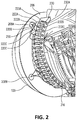
Fig. 2 illustrates a perspective view of an example of a flexible band electrical component mount in accordance with an example of the disclosure. -
Fig. 3 illustrates a perspective view of another example of a flexible band electrical component mount in accordance with an example of the disclosure. -
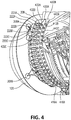
Fig. 4 illustrates a perspective view of a further example of a flexible band electrical component mount in accordance with the disclosure. -
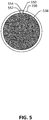
Fig. 5 illustrates a cutaway view of an aircraft propulsor with a flexible band electrical component mount in accordance with the disclosure. -
Fig. 6 is a flowchart detailing a technique for testing of aircraft propulsors with the flexible band electrical component mount in accordance with examples of the disclosure. - Examples of the disclosure and their advantages are best understood by referring to the detailed description that follows. It should be appreciated that like reference numerals are used to identify like elements illustrated in one or more of the figures.
- Flexible band electrical component mounts are described in the disclosure herein in accordance with one or more embodiments. The flexible band electrical component mount may allow instruments to be coupled to an aircraft propulsor. In certain examples, the flexible band electrical component mount may be configured to mount a high number of instruments (e.g., 50 or more instruments). The flexible band electrical component mount may include a flexible band that includes one or more electrical component openings, the electrical component opening configured to receive an electrical component (e.g., an instrument). The flexible band may be configured to wrap around a portion of the aircraft propulsor and may include a coupler to couple together at least two portions of the flexible band to hold the flexible band around the portion of the aircraft propulsor.
-
Fig. 1 illustrates a perspective view of an aircraft propulsor in accordance with an example of the disclosure.Aircraft propulsor 100 includes anacelle 102 and afan 136. In the example shown inFig. 1 , thenacelle 102 contains thefan 136 and other components of theaircraft propulsor 100 used to produce trust, but other examples of the aircraft propulsor may arrange the fan so that the fan is not contained by the nacelle (e.g., in, for example, a turboprop configuration). Thenacelle 102 may also include one or more portions that may be moved and/or removed to allow a technician or other personnel to access internal components of theaircraft propulsor 100 to, for example, insert and/or mount one or more electrical components (e.g., instruments) for monitoring one or more conditions of theaircraft propulsor 100. - The
fan 136 intakes and/or energizes air flowing into thenacelle 102, such as in anairflow direction 140A. Air that flows into thenacelle 102 viaairflow direction 140A may flow through various internal flow paths within thenacelle 102. -
Fig. 2 illustrates a perspective view of an example of a flexible band electrical component mount in accordance with an example of the disclosure. Theaircraft propulsor 100 shown inFig. 2 includes abulkhead 206. Thebulkhead 206 includes pass-throughs Fig. 2 shows theaircraft propulsor 100 with one or more portions of thenacelle 102 removed to allow mounting, removal, and/or access to electrical components coupled to theaircraft propulsor 100 via flexible bandelectrical component mount 216. - The flexible band
electrical component mount 216 includes aflexible band 230 with one or more electrical component openings, such aselectrical component openings 232A-C. Theflexible band 230 may be sized and/or configured to surround at least a portion of theaircraft propulsor 100. For example, theflexible band 230 may be configured to wrap around a perimeter of a core engine of the aircraft propulsor 100 (e.g., a portion of theaircraft propulsor 100 normally covered by a nacelle). - The
flexible band 230 includes one or more electrical component openings such aselectrical component openings 232A-C as well as other electrical component openings. Each of theelectrical component openings 232A-C may be configured to receive one or more electrical components. For example, each of theelectrical components 220A-C may be disposed within one of theelectrical component openings 232A-C. Each of theelectrical component openings 232A-C may, for example, be a cavity within theflexible band 230 configured to receive the one or more electrical components. In certain examples, theelectrical component openings 232A-C may be flexible and may allow for insertion of an electrical component into the electrical component opening. After the electrical component has been inserted, the electrical component opening may then hold the electrical component within the electrical component opening. In certain such examples, theelectrical component openings 232A-C may be sized smaller than the electrical component that the openings are configured to receive (e.g., the inner diameters of theelectrical component openings 232A-C are smaller than the outer diameters of theelectrical components 220A-C) and theelectrical components 220A-C may deform theelectrical component openings 232A-C when inserted. Such deformation may then hold theelectrical components 220A-C in place after insertion. - The
electrical components 220A-C may be any electrical component. In certain examples, theelectrical components 220A-C may be configured to determine a parameter of theaircraft propulsor 100. As such,electrical components 220A-C may be, for example, transducers such as accelerometers (e.g., load cells, air flow sensors, potentiometers, and other transducers) as well as gyroscopes and/or other such sensors. - Certain testing applications may require a plurality of electrical components. As aircraft propulsors become more complicated and as data acquisition technology advances, the amount of electrical components required to acquire data associated with the aircraft propulsor may increase. As such, techniques such as mounting brackets for electrical components on the bulkhead of the aircraft propulsor may not allow for enough electrical components to be mounted to fully monitor and/or acquire the needed data for modern aircraft propulsor data acquisition techniques.
- By contrast, the
flexible band 230 may be configured to hold a greater number of electrical components than other techniques. Also, theflexible band 230 may be configured to wrap around itself one or more times and, thus, allow for a longerflexible band 230 with a greater number of electrical component openings, further increasing the number of electrical components that may be carried by theflexible band 230. Accordingly, the flexible band electrical component mount may allow for a larger number of electrical components to be mounted. - In certain examples, such as during testing of aircraft propulsors, the nacelle or a portion of the nacelle may be removed and the testing procedure may be performed with the portion of the nacelle removed. With the nacelle removed, the
flexible band 230 may wrap around itself a larger amount of times than with the nacelle installed, and thus may be longer and allow for an even greater number of electrical components to be installed. - Referring back to
Fig. 2 , theelectrical components 220A-C includeswires 222A-C, respectively. Thewires 222A-C are routed through the pass-through 208A. In certain examples, thewires 222A-C are coupled together bywire organizer 250. Thewire organizer 250 may couple together thewires 222A-C, as well as other wires, to couple the wires together as one large bundle that may then be routed through the pass-through 208A. -
Fig. 3 illustrates a perspective view of another example of a flexible band electrical component mount in accordance with an example of the disclosure. Theaircraft propulsor 100 shown inFig. 3 also includes abulkhead 206 that includes pass-throughs Fig. 3 illustrates a flexible bandelectrical component mount 316 that includes aflexible band 330 with one or more electrical component openings (e.g.,electrical component openings 332A-C) configured to hold one or more electrical components (e.g.,electrical components 220A-C). - The
flexible band 330 is held against at least a portion of theaircraft propulsor 100 via astrap 340. Thestrap 340 may be, for example, an elastic strap that may wrap around a portion of the flexible band 330 (e.g., an outer perimeter of the flexible band 330). Thestrap 340 may be elastic and/or may be configured to wrap around theflexible band 330 so that theflexible band 330 is at least partially deformed to securely hold theflexible band 330 against theaircraft propulsor 100. In certain examples, thestrap 340 may be a continuous loop that is stretched over theaircraft propulsor 100 to secure theflexible band 330 against theaircraft propulsor 100. In other examples, thestrap 340 may include a first strap end and a second strap end and the first strap end and the second strap end may be secured to each other after wrapping thestrap 340 around theflexible band 330 to hold theflexible band 330 against theaircraft propulsor 100. -
Fig. 4 illustrates a perspective view of a further example of a flexible band electrical component mount in accordance with the disclosure. Theaircraft propulsor 100 shown inFig. 4 also includes abulkhead 206 that includes pass-throughs Fig. 4 illustrates flexible band electrical component mounts 416A and 416B that includesflexible bands electrical component openings 432A-C and 442A-C) configured to hold one or more electrical components. - As illustrated in
Fig. 4 , theflexible band 430A of theelectrical component mount 416A overlaps theflexible band 430B of theelectrical component mount 416B. In certain examples, theflexible band flexible band 430A may be a first portion andflexible band 430B may be a second portion of the same flexible band and such a flexible band may wrap around itself so that, for example,flexible band 430B is wrapped around the outside of theflexible band 430A), may be connected (e.g., the flexible band 430 may be connected to theflexible band 430A via one or more fasteners and may be wrapped around the outside of theflexible band 430A), and/or may be separate flexible bands (e.g., theflexible bands flexible band 430B may be wrapped around the outside of theflexible band 430A and, thus,flexible band 430B may be of a larger diameter thanflexible band 430A). Whether theflexible band flexible bands 430A and/or 430B, and/or another such flexible band. Accordingly, the flexible bands may be "layered" as needed to hold the required number of electrical components. - In certain additional examples, the
flexible bands flexible band 430B may include a first end and a second end and may be configured to wrap around theflexible band 430A. The first end and the second end may then be connected to each other and, when connected, may hold both theflexible band 430A and theflexible band 430B against a portion of the aircraft propulsor 100 (e.g., the core engine of the aircraft propulsor 100). Certain other such examples may include a strap that may wrap around theflexible band 430A and/or 430B to hold theflexible band 430A and/or 430B in place. - In other examples, the
flexible band flexible band 430A and/or 430B may be coupled to a second portion of theflexible band 430A and/or 430B. When coupled together, theflexible band 430A and/or 430B may positioned such that theflexible band 430A and/or 430B may be held against a portion of the aircraft propulsor 100 (e.g., the core engine of the aircraft propulsor 100). In certain examples, theflexible band 430A and/or 430B may be held in a manner that prevents theflexible band 430A and/or 430B from decoupling from the portion of theaircraft propulsor 100. For example, theflexible band 430A and/or 430B may fully wrap around the portion of theaircraft propulsor 100 and, thus, not be removed from the portion of theaircraft propulsor 100 unless the first portion is decoupled from the second portion. -
Fig. 5 illustrates a cutaway view of an aircraft propulsor with a flexible band electrical component mount in accordance with the disclosure.Fig. 5 illustrates acore engine 538 of an aircraft propulsor with aflexible band 230.Fig. 5 illustrates an example of coupling together theflexible band 230 so that it wraps around thecore engine 538. - In
Fig. 5 , theflexible band 230 is coupled to (e.g., wrapped around) thecore engine 538. Theflexible band 230 includes afirst end 550 and asecond end 552. Thefirst end 550 and thesecond end 552 may be coupled together via thecoupler 554. As such, when thefirst end 550 is coupled to thesecond end 552 via thecoupler 554, theflexible band 230 may be wrapped around thecore engine 538. In certain examples, theflexible band 230 may wrap around the core engine 538 a plurality of times and, thus, one portion of theflexible band 230 may overlap another portion of theflexible band 230. - The
coupler 554 may be, for example, a mechanical coupler such as one or more snaps, hooks, hinges, connectors, fasteners, adhesives, Velcro straps, and/or other such couplers. Also, in certain other examples, thecoupler 554 may be configured to couple together portions of two of more flexible bands. -
Fig. 6 is a flowchart detailing a technique for testing of aircraft propulsors with the flexible band electrical component mount in accordance with examples of the disclosure.
Inblock 602, electrical components are inserted into electrical component openings of a flexible band. In certain examples, each electrical component opening may be configured to receive one electrical component, but other examples may include one or more electrical component openings configured to receive more than one electrical component. - In
block 604, the flexible band may be positioned around at least a portion of the aircraft propulsor. For example, the flexible band may be hung off of a portion of the aircraft propulsor and/or may be wrapped around the portion of the aircraft propulsor. Additionally, in certain examples, a plurality of flexible bands may be positioned around at least a portion of the aircraft propulsor. In certain examples, the plurality of flexible bands may wrap around each other, but in other examples, the flexible bands may wrap around different portions of the aircraft propulsor. - One portion of the flexible band may then be coupled to another portion of the flexible band in
block 606. Coupling the portions of the flexible band together may hold the flexible band against the portion of the aircraft propulsor. In certain examples, the portions may be portions of the same flexible band, but in other examples, the portions may be portions of two or more different flexible bands. In certain other examples, a strap may be wrapped around the flexible band or plurality of flexible bands to hold the one or more bands around the portion of the aircraft propulsor. - In
block 608, wires of the electrical components may be organized. As such, one or more wire organizers may be used to hold a plurality of wires to organize the wires. In certain examples, the wire organizers may hold the wires to aid in threading the wires through one or more pass-throughs located on a bulkhead of the aircraft propulsor. After the wires are organized, the electrical components may then electrically connect to one or more testing modules to, for example, deliver data to such testing modules. The testing modules may be located on the aircraft propulsor and/or may be remotely located and data may be delivered via, for example, one or more data connections. - In
block 610, a test sequence may be performed using the one or more electrical components. During the test sequence, the aircraft propulsor may be operated and the one or more electrical components may output data. In certain examples, the data may be related to operation of the aircraft propulsor. Further, the disclosure comprises embodiments according to the following clauses: - Clause 1. An apparatus comprising:
- a flexible band comprising at least one electrical component opening, wherein the electrical component opening is configured to receive an electrical component configured to determine a parameter associated with an aircraft propulsor, and wherein the flexible band is configured to surround at least a portion of the aircraft propulsor; and
- a band coupler configured to couple together at least two portions of the flexible band.
- Clause 2. The apparatus of Clause 1, wherein the electrical component opening is configured to receive a transducer.
- Clause 3. The apparatus of any of Clauses 1-2, further comprising a strap configured to couple to the flexible band and hold the flexible band against the portion of the aircraft propulsor.
- Clause 4. The apparatus of any of Clauses 1-3, wherein the flexible band is configured to surround at least the portion of the aircraft propulsor a plurality of times.
- Clause 5. The apparatus of any of Clauses 1-4, wherein the flexible band comprises a plurality of electrical component openings each configured to receive an electrical component.
- Clause 6. The apparatus of Clause 5, further comprising a wire organizer configured to hold at least a plurality of wires coupled to the electrical components.
- Clause 7. The apparatus of any of Clauses 1-6, wherein the flexible band is configured to be disposed within a nacelle of the aircraft propulsor.
- Clause 8. An aircraft propulsor comprising:
- an engine;
- a plurality of electrical components configured to determine a parameter associated with the engine;
- a flexible band comprising a at least one electrical component opening, wherein the electrical component opening is configured to receive one or more of the electrical components, and wherein the flexible band is configured to surround at least a portion of the engine;
- a band coupler configured to couple together at least two portions of the flexible band; and
- a nacelle configured to surround the engine and the flexible band.
- Clause 9. The aircraft propulsor of Clause 8, wherein the electrical component is a transducer.
- Clause 10. The aircraft propulsor of any of Clauses 8-9, further comprising a strap configured to couple to the flexible band and hold the flexible band against the portion of the engine.
- Clause 11. The aircraft propulsor of any of Clauses 8-10, wherein the flexible band is configured to surround at least the portion of the engine a plurality of times.
- Clause 12. The aircraft propulsor of any of Clauses 8-11, further comprising a bulkhead coupled to the engine and comprising at least one pass-through, wherein at least one of the plurality of electrical components comprises a wire configured to route through the pass-through.
- Clause 13. The aircraft propulsor of Clause 12, wherein the flexible band comprises a plurality of electrical component openings each configured to receive an electrical component and further comprising a wire organizer configured to hold at least a plurality of wires coupled to the electrical components, wherein each of the plurality of wires is configured to route through the pass-through.
- Clause 14. A method comprising:
- disposing an electrical component configured to determine a parameter associated with an aircraft propulsor within an electrical component opening of a flexible band;
- surrounding at least a portion of the aircraft propulsor with the flexible band; and
- coupling together at least two portions of the flexible band.
- Clause 15. The method of Clause 14, wherein at least one of the electrical components is a transducer.
- Clause 16. The method of any of Clauses 14-15, further comprising disposing a plurality of electrical components within a plurality of electrical component openings.
- Clause 17. The method of Clause 16, wherein each of the plurality of electrical components is disposed within one of the electrical component openings.
- Clause 18. The method of Clause 16, further comprising:
- threading a plurality of wire through a pass-through of a bulkhead of the aircraft propulsor, wherein each of the plurality of wires is coupled to one of the electrical components.
- Clause 19. The method of Clause 18, further comprising:
- coupling a wire organizer to a plurality of the wires to hold the plurality of wires.
- Clause 20. The method of any of Clauses 14-19, further comprising:
- coupling a strap to the flexible band to hold the flexible band against the portion of the engine.
- Examples described above illustrate but do not limit the invention. It should also be understood that numerous modifications and variations are possible in accordance with the principles of the present invention. Accordingly, the scope of the invention is defined only by the following claims.
Claims (15)
- An aircraft propulsor (100) comprising:an engine;a plurality of electrical components (220A-C) configured to determine a parameter associated with the engine;a flexible band (230) comprising a at least one electrical component opening (232A-C), wherein the electrical component opening (232A-C)is configured to receive one or more of the electrical components (220A-C), and wherein the flexible band (230) is configured to surround at least a portion of the engine;a band coupler (554) configured to couple together at least two portions of the flexible band (230); anda nacelle configured to surround the engine and the flexible band (230).
- The aircraft propulsor (100) of claim 1, wherein the electrical component (220A-C) is a transducer.
- The aircraft propulsor (100) of claims 1 or 2, further comprising a strap (340) configured to couple to the flexible band (230) and hold the flexible band (230) against the portion of the engine.
- The aircraft propulsor of any one of claims 1-3, wherein the flexible band (230) is configured to surround at least the portion of the engine a plurality of times.
- The aircraft propulsor of any one of claims 1-4, further comprising a bulkhead (206) coupled to the engine and comprising at least one pass-through (208A and 208B), wherein at least one of the plurality of electrical components (220A-C) comprises a wire configured to route through the pass-through (208A and 208B).
- The aircraft propulsor of claim 5, wherein the flexible band (230) comprises a plurality of electrical component openings (232A-C) each configured to receive an electrical component (220A-C).
- The apparatus of claim 6, further comprising a wire organizer (250) configured to hold at least a plurality of wires coupled to the electrical components.
- The apparatus of any one of claims 1-7, wherein the flexible band (230) is configured to be disposed within a nacelle of the aircraft propulsor (100).
- A method comprising:disposing an electrical component (220A-C)configured to determine a parameter associated with an aircraft propulsor (100) within an electrical component opening (232A-C)of a flexible band (230);surrounding at least a portion of the aircraft propulsor (100) with the flexible band (230); andcoupling together at least two portions of the flexible band (230).
- The method of claim 9, wherein at least one of the electrical components (220A-C) is a transducer.
- The method of claims 9 or 10, further comprising disposing a plurality of electrical components (220A-C) within a plurality of electrical component openings (232A-C).
- The method of claim 11, wherein each of the plurality of electrical components (220A-C) is disposed within one of the electrical component openings (232A-C).
- The method of claim 11, further comprising:threading a plurality of wire through a pass-through (208A and 208B) of a bulkhead (206) of the aircraft propulsor (100), wherein each of the plurality of wires is coupled to one of the electrical components (220A-C).
- The method of claim 13, further comprising:coupling a wire organizer (250) to a plurality of the wires to hold the plurality of wires.
- The method of any one of claims 9-14, further comprising:coupling a strap (340) to the flexible band (230) to hold the flexible band (230) against the portion of the engine.
Applications Claiming Priority (1)
| Application Number | Priority Date | Filing Date | Title |
|---|---|---|---|
| US15/408,190 US10822995B2 (en) | 2017-01-17 | 2017-01-17 | Flexible band electrical component mounts and methods |
Publications (2)
| Publication Number | Publication Date |
|---|---|
| EP3348797A1 true EP3348797A1 (en) | 2018-07-18 |
| EP3348797B1 EP3348797B1 (en) | 2019-09-11 |
Family
ID=60574390
Family Applications (1)
| Application Number | Title | Priority Date | Filing Date |
|---|---|---|---|
| EP17204155.0A Active EP3348797B1 (en) | 2017-01-17 | 2017-11-28 | Flexible band electrical component mounts and methods |
Country Status (3)
| Country | Link |
|---|---|
| US (1) | US10822995B2 (en) |
| EP (1) | EP3348797B1 (en) |
| CN (1) | CN108327920B (en) |
Families Citing this family (3)
| Publication number | Priority date | Publication date | Assignee | Title |
|---|---|---|---|---|
| US11125157B2 (en) | 2017-09-22 | 2021-09-21 | The Boeing Company | Advanced inlet design |
| BR102022003769A2 (en) | 2021-05-04 | 2022-11-16 | The Boeing Company | NACELE ENTRY STRUCTURE OF AN ENGINE ASSEMBLY |
| US11885228B2 (en) * | 2022-02-09 | 2024-01-30 | General Electric Company | System and method for inspecting fan blade tip clearance relative to an abradable fan case |
Citations (3)
| Publication number | Priority date | Publication date | Assignee | Title |
|---|---|---|---|---|
| US20130161093A1 (en) * | 2011-12-22 | 2013-06-27 | Rolls-Royce Plc | Electrical harness |
| US20130294900A1 (en) * | 2012-05-03 | 2013-11-07 | Rohr, Inc. | Mounting system for a nacelle fire detection system |
| EP2708703A2 (en) * | 2012-09-12 | 2014-03-19 | General Electric Company | Mounting device and method of assembling the same |
Family Cites Families (10)
| Publication number | Priority date | Publication date | Assignee | Title |
|---|---|---|---|---|
| US4991431A (en) | 1990-01-31 | 1991-02-12 | General Motors Corporation | Method of monitoring a mount system for an aircraft engine |
| US5664810A (en) * | 1995-09-26 | 1997-09-09 | The Boeing Company | Fireproof electrical wire housing |
| US20100095525A1 (en) * | 2008-10-22 | 2010-04-22 | Shaw Alan Terence | Gas turbine combustor repair using a make-up ring |
| GB2476244B (en) | 2009-12-16 | 2013-04-03 | Rolls Royce Plc | A transducer assembly |
| GB2498006B (en) * | 2011-12-22 | 2014-07-09 | Rolls Royce Plc | Gas turbine engine systems |
| US9478896B2 (en) * | 2011-12-22 | 2016-10-25 | Rolls-Royce Plc | Electrical connectors |
| US20140161151A1 (en) * | 2012-12-12 | 2014-06-12 | John Proctor | Line & pipe flexible temperature sensor assembly |
| US9733130B2 (en) * | 2013-05-10 | 2017-08-15 | Illinois Tool Works Inc. | Temperature sensor belt |
| EP3055541B1 (en) * | 2013-10-07 | 2021-12-08 | Rohr, Inc. | Hybrid inner fixed structure with metallic and composite construction |
| CN204301890U (en) * | 2014-12-30 | 2015-04-29 | 江苏由甲申田新能源科技有限公司 | A kind of rubber sheath formula temperature sensor |
-
2017
- 2017-01-17 US US15/408,190 patent/US10822995B2/en active Active
- 2017-11-28 EP EP17204155.0A patent/EP3348797B1/en active Active
- 2017-12-25 CN CN201711416603.XA patent/CN108327920B/en active Active
Patent Citations (3)
| Publication number | Priority date | Publication date | Assignee | Title |
|---|---|---|---|---|
| US20130161093A1 (en) * | 2011-12-22 | 2013-06-27 | Rolls-Royce Plc | Electrical harness |
| US20130294900A1 (en) * | 2012-05-03 | 2013-11-07 | Rohr, Inc. | Mounting system for a nacelle fire detection system |
| EP2708703A2 (en) * | 2012-09-12 | 2014-03-19 | General Electric Company | Mounting device and method of assembling the same |
Also Published As
| Publication number | Publication date |
|---|---|
| US20180202313A1 (en) | 2018-07-19 |
| US10822995B2 (en) | 2020-11-03 |
| EP3348797B1 (en) | 2019-09-11 |
| CN108327920B (en) | 2023-03-24 |
| CN108327920A (en) | 2018-07-27 |
Similar Documents
| Publication | Publication Date | Title |
|---|---|---|
| EP3348797B1 (en) | Flexible band electrical component mounts and methods | |
| US9204497B2 (en) | Electrical structure having a grounding plane | |
| EP3385509B1 (en) | Wave guide with fluid passages | |
| US9478896B2 (en) | Electrical connectors | |
| US20140044400A1 (en) | Fiber management frames having modular tray holder | |
| US20140326058A1 (en) | Engine health monitoring | |
| CN103828139B (en) | Cable assembly and its communication equipment for connecting user's line and data/address bus | |
| EP3086194B1 (en) | Electronic module integration for harsh environment machines | |
| US4580910A (en) | Engine exhaust gas test harness | |
| US20020177978A1 (en) | Digital data acquisition system for manitoring and remote testing of gas and steam turbine performance parameters | |
| CN103837939B (en) | Connecting device | |
| US20260104444A1 (en) | Locomotive engine injection harness tester | |
| EP2423696A1 (en) | Generator tester | |
| US9151921B2 (en) | Apparatus for making uniform optical fiber bundles in power generators | |
| KR100717480B1 (en) | tester | |
| CN216894642U (en) | Cooling device and aeroengine test system | |
| US6973250B2 (en) | Method of and apparatus for managing a length of optical fibre | |
| CN203480861U (en) | Multi-core cable | |
| CN116209819A (en) | Turbine engine including improved wire harness support | |
| US20060179933A1 (en) | Pressure testing assemblies for use in flow bodies and methods of testing flow bodies | |
| CN223691928U (en) | A force sensor calibration device | |
| EP3220096A1 (en) | Flex circuit connector configuration | |
| CN116222754B (en) | Fault investigation method for marine gas turbine vibration monitoring system | |
| JP3662674B2 (en) | Optical fiber cable closure | |
| CN208926380U (en) | A kind of sense of hearing directive property acoustic measurement bracket |
Legal Events
| Date | Code | Title | Description |
|---|---|---|---|
| PUAI | Public reference made under article 153(3) epc to a published international application that has entered the european phase |
Free format text: ORIGINAL CODE: 0009012 |
|
| STAA | Information on the status of an ep patent application or granted ep patent |
Free format text: STATUS: EXAMINATION IS IN PROGRESS |
|
| 17P | Request for examination filed |
Effective date: 20171128 |
|
| AK | Designated contracting states |
Kind code of ref document: A1 Designated state(s): AL AT BE BG CH CY CZ DE DK EE ES FI FR GB GR HR HU IE IS IT LI LT LU LV MC MK MT NL NO PL PT RO RS SE SI SK SM TR |
|
| AX | Request for extension of the european patent |
Extension state: BA ME |
|
| GRAP | Despatch of communication of intention to grant a patent |
Free format text: ORIGINAL CODE: EPIDOSNIGR1 |
|
| INTG | Intention to grant announced |
Effective date: 20190617 |
|
| GRAS | Grant fee paid |
Free format text: ORIGINAL CODE: EPIDOSNIGR3 |
|
| STAA | Information on the status of an ep patent application or granted ep patent |
Free format text: STATUS: GRANT OF PATENT IS INTENDED |
|
| GRAA | (expected) grant |
Free format text: ORIGINAL CODE: 0009210 |
|
| STAA | Information on the status of an ep patent application or granted ep patent |
Free format text: STATUS: THE PATENT HAS BEEN GRANTED |
|
| AK | Designated contracting states |
Kind code of ref document: B1 Designated state(s): AL AT BE BG CH CY CZ DE DK EE ES FI FR GB GR HR HU IE IS IT LI LT LU LV MC MK MT NL NO PL PT RO RS SE SI SK SM TR |
|
| REG | Reference to a national code |
Ref country code: GB Ref legal event code: FG4D |
|
| REG | Reference to a national code |
Ref country code: CH Ref legal event code: EP |
|
| REG | Reference to a national code |
Ref country code: AT Ref legal event code: REF Ref document number: 1178717 Country of ref document: AT Kind code of ref document: T Effective date: 20190915 |
|
| REG | Reference to a national code |
Ref country code: DE Ref legal event code: R096 Ref document number: 602017006963 Country of ref document: DE Ref country code: IE Ref legal event code: FG4D |
|
| REG | Reference to a national code |
Ref country code: NL Ref legal event code: MP Effective date: 20190911 |
|
| REG | Reference to a national code |
Ref country code: LT Ref legal event code: MG4D |
|
| PG25 | Lapsed in a contracting state [announced via postgrant information from national office to epo] |
Ref country code: FI Free format text: LAPSE BECAUSE OF FAILURE TO SUBMIT A TRANSLATION OF THE DESCRIPTION OR TO PAY THE FEE WITHIN THE PRESCRIBED TIME-LIMIT Effective date: 20190911 Ref country code: HR Free format text: LAPSE BECAUSE OF FAILURE TO SUBMIT A TRANSLATION OF THE DESCRIPTION OR TO PAY THE FEE WITHIN THE PRESCRIBED TIME-LIMIT Effective date: 20190911 Ref country code: LT Free format text: LAPSE BECAUSE OF FAILURE TO SUBMIT A TRANSLATION OF THE DESCRIPTION OR TO PAY THE FEE WITHIN THE PRESCRIBED TIME-LIMIT Effective date: 20190911 Ref country code: NO Free format text: LAPSE BECAUSE OF FAILURE TO SUBMIT A TRANSLATION OF THE DESCRIPTION OR TO PAY THE FEE WITHIN THE PRESCRIBED TIME-LIMIT Effective date: 20191211 Ref country code: BG Free format text: LAPSE BECAUSE OF FAILURE TO SUBMIT A TRANSLATION OF THE DESCRIPTION OR TO PAY THE FEE WITHIN THE PRESCRIBED TIME-LIMIT Effective date: 20191211 Ref country code: SE Free format text: LAPSE BECAUSE OF FAILURE TO SUBMIT A TRANSLATION OF THE DESCRIPTION OR TO PAY THE FEE WITHIN THE PRESCRIBED TIME-LIMIT Effective date: 20190911 |
|
| PG25 | Lapsed in a contracting state [announced via postgrant information from national office to epo] |
Ref country code: ES Free format text: LAPSE BECAUSE OF FAILURE TO SUBMIT A TRANSLATION OF THE DESCRIPTION OR TO PAY THE FEE WITHIN THE PRESCRIBED TIME-LIMIT Effective date: 20190911 Ref country code: GR Free format text: LAPSE BECAUSE OF FAILURE TO SUBMIT A TRANSLATION OF THE DESCRIPTION OR TO PAY THE FEE WITHIN THE PRESCRIBED TIME-LIMIT Effective date: 20191212 Ref country code: RS Free format text: LAPSE BECAUSE OF FAILURE TO SUBMIT A TRANSLATION OF THE DESCRIPTION OR TO PAY THE FEE WITHIN THE PRESCRIBED TIME-LIMIT Effective date: 20190911 Ref country code: LV Free format text: LAPSE BECAUSE OF FAILURE TO SUBMIT A TRANSLATION OF THE DESCRIPTION OR TO PAY THE FEE WITHIN THE PRESCRIBED TIME-LIMIT Effective date: 20190911 Ref country code: AL Free format text: LAPSE BECAUSE OF FAILURE TO SUBMIT A TRANSLATION OF THE DESCRIPTION OR TO PAY THE FEE WITHIN THE PRESCRIBED TIME-LIMIT Effective date: 20190911 |
|
| REG | Reference to a national code |
Ref country code: AT Ref legal event code: MK05 Ref document number: 1178717 Country of ref document: AT Kind code of ref document: T Effective date: 20190911 |
|
| PG25 | Lapsed in a contracting state [announced via postgrant information from national office to epo] |
Ref country code: PL Free format text: LAPSE BECAUSE OF FAILURE TO SUBMIT A TRANSLATION OF THE DESCRIPTION OR TO PAY THE FEE WITHIN THE PRESCRIBED TIME-LIMIT Effective date: 20190911 Ref country code: RO Free format text: LAPSE BECAUSE OF FAILURE TO SUBMIT A TRANSLATION OF THE DESCRIPTION OR TO PAY THE FEE WITHIN THE PRESCRIBED TIME-LIMIT Effective date: 20190911 Ref country code: IT Free format text: LAPSE BECAUSE OF FAILURE TO SUBMIT A TRANSLATION OF THE DESCRIPTION OR TO PAY THE FEE WITHIN THE PRESCRIBED TIME-LIMIT Effective date: 20190911 Ref country code: NL Free format text: LAPSE BECAUSE OF FAILURE TO SUBMIT A TRANSLATION OF THE DESCRIPTION OR TO PAY THE FEE WITHIN THE PRESCRIBED TIME-LIMIT Effective date: 20190911 Ref country code: AT Free format text: LAPSE BECAUSE OF FAILURE TO SUBMIT A TRANSLATION OF THE DESCRIPTION OR TO PAY THE FEE WITHIN THE PRESCRIBED TIME-LIMIT Effective date: 20190911 Ref country code: EE Free format text: LAPSE BECAUSE OF FAILURE TO SUBMIT A TRANSLATION OF THE DESCRIPTION OR TO PAY THE FEE WITHIN THE PRESCRIBED TIME-LIMIT Effective date: 20190911 Ref country code: PT Free format text: LAPSE BECAUSE OF FAILURE TO SUBMIT A TRANSLATION OF THE DESCRIPTION OR TO PAY THE FEE WITHIN THE PRESCRIBED TIME-LIMIT Effective date: 20200113 |
|
| PG25 | Lapsed in a contracting state [announced via postgrant information from national office to epo] |
Ref country code: SM Free format text: LAPSE BECAUSE OF FAILURE TO SUBMIT A TRANSLATION OF THE DESCRIPTION OR TO PAY THE FEE WITHIN THE PRESCRIBED TIME-LIMIT Effective date: 20190911 Ref country code: SK Free format text: LAPSE BECAUSE OF FAILURE TO SUBMIT A TRANSLATION OF THE DESCRIPTION OR TO PAY THE FEE WITHIN THE PRESCRIBED TIME-LIMIT Effective date: 20190911 Ref country code: IS Free format text: LAPSE BECAUSE OF FAILURE TO SUBMIT A TRANSLATION OF THE DESCRIPTION OR TO PAY THE FEE WITHIN THE PRESCRIBED TIME-LIMIT Effective date: 20200224 Ref country code: CZ Free format text: LAPSE BECAUSE OF FAILURE TO SUBMIT A TRANSLATION OF THE DESCRIPTION OR TO PAY THE FEE WITHIN THE PRESCRIBED TIME-LIMIT Effective date: 20190911 |
|
| REG | Reference to a national code |
Ref country code: DE Ref legal event code: R097 Ref document number: 602017006963 Country of ref document: DE |
|
| PLBE | No opposition filed within time limit |
Free format text: ORIGINAL CODE: 0009261 |
|
| STAA | Information on the status of an ep patent application or granted ep patent |
Free format text: STATUS: NO OPPOSITION FILED WITHIN TIME LIMIT |
|
| PG2D | Information on lapse in contracting state deleted |
Ref country code: IS |
|
| PG25 | Lapsed in a contracting state [announced via postgrant information from national office to epo] |
Ref country code: MC Free format text: LAPSE BECAUSE OF FAILURE TO SUBMIT A TRANSLATION OF THE DESCRIPTION OR TO PAY THE FEE WITHIN THE PRESCRIBED TIME-LIMIT Effective date: 20190911 Ref country code: LU Free format text: LAPSE BECAUSE OF NON-PAYMENT OF DUE FEES Effective date: 20191128 Ref country code: DK Free format text: LAPSE BECAUSE OF FAILURE TO SUBMIT A TRANSLATION OF THE DESCRIPTION OR TO PAY THE FEE WITHIN THE PRESCRIBED TIME-LIMIT Effective date: 20190911 Ref country code: IS Free format text: LAPSE BECAUSE OF FAILURE TO SUBMIT A TRANSLATION OF THE DESCRIPTION OR TO PAY THE FEE WITHIN THE PRESCRIBED TIME-LIMIT Effective date: 20200112 |
|
| 26N | No opposition filed |
Effective date: 20200615 |
|
| REG | Reference to a national code |
Ref country code: BE Ref legal event code: MM Effective date: 20191130 |
|
| PG25 | Lapsed in a contracting state [announced via postgrant information from national office to epo] |
Ref country code: SI Free format text: LAPSE BECAUSE OF FAILURE TO SUBMIT A TRANSLATION OF THE DESCRIPTION OR TO PAY THE FEE WITHIN THE PRESCRIBED TIME-LIMIT Effective date: 20190911 |
|
| PG25 | Lapsed in a contracting state [announced via postgrant information from national office to epo] |
Ref country code: IE Free format text: LAPSE BECAUSE OF NON-PAYMENT OF DUE FEES Effective date: 20191128 |
|
| PG25 | Lapsed in a contracting state [announced via postgrant information from national office to epo] |
Ref country code: BE Free format text: LAPSE BECAUSE OF NON-PAYMENT OF DUE FEES Effective date: 20191130 |
|
| PG25 | Lapsed in a contracting state [announced via postgrant information from national office to epo] |
Ref country code: CY Free format text: LAPSE BECAUSE OF FAILURE TO SUBMIT A TRANSLATION OF THE DESCRIPTION OR TO PAY THE FEE WITHIN THE PRESCRIBED TIME-LIMIT Effective date: 20190911 |
|
| REG | Reference to a national code |
Ref country code: CH Ref legal event code: PL |
|
| PG25 | Lapsed in a contracting state [announced via postgrant information from national office to epo] |
Ref country code: MT Free format text: LAPSE BECAUSE OF FAILURE TO SUBMIT A TRANSLATION OF THE DESCRIPTION OR TO PAY THE FEE WITHIN THE PRESCRIBED TIME-LIMIT Effective date: 20190911 Ref country code: HU Free format text: LAPSE BECAUSE OF FAILURE TO SUBMIT A TRANSLATION OF THE DESCRIPTION OR TO PAY THE FEE WITHIN THE PRESCRIBED TIME-LIMIT; INVALID AB INITIO Effective date: 20171128 |
|
| PG25 | Lapsed in a contracting state [announced via postgrant information from national office to epo] |
Ref country code: CH Free format text: LAPSE BECAUSE OF NON-PAYMENT OF DUE FEES Effective date: 20201130 Ref country code: LI Free format text: LAPSE BECAUSE OF NON-PAYMENT OF DUE FEES Effective date: 20201130 |
|
| PG25 | Lapsed in a contracting state [announced via postgrant information from national office to epo] |
Ref country code: TR Free format text: LAPSE BECAUSE OF FAILURE TO SUBMIT A TRANSLATION OF THE DESCRIPTION OR TO PAY THE FEE WITHIN THE PRESCRIBED TIME-LIMIT Effective date: 20190911 |
|
| PG25 | Lapsed in a contracting state [announced via postgrant information from national office to epo] |
Ref country code: MK Free format text: LAPSE BECAUSE OF FAILURE TO SUBMIT A TRANSLATION OF THE DESCRIPTION OR TO PAY THE FEE WITHIN THE PRESCRIBED TIME-LIMIT Effective date: 20190911 |
|
| GRAP | Despatch of communication of intention to grant a patent |
Free format text: ORIGINAL CODE: EPIDOSNIGR1 |
|
| P01 | Opt-out of the competence of the unified patent court (upc) registered |
Effective date: 20230516 |
|
| PGFP | Annual fee paid to national office [announced via postgrant information from national office to epo] |
Ref country code: DE Payment date: 20251128 Year of fee payment: 9 |
|
| PGFP | Annual fee paid to national office [announced via postgrant information from national office to epo] |
Ref country code: GB Payment date: 20251127 Year of fee payment: 9 |
|
| PGFP | Annual fee paid to national office [announced via postgrant information from national office to epo] |
Ref country code: FR Payment date: 20251125 Year of fee payment: 9 |