EP3348521A1 - Process of electrochemical oxidation - Google Patents
Process of electrochemical oxidation Download PDFInfo
- Publication number
- EP3348521A1 EP3348521A1 EP17305040.2A EP17305040A EP3348521A1 EP 3348521 A1 EP3348521 A1 EP 3348521A1 EP 17305040 A EP17305040 A EP 17305040A EP 3348521 A1 EP3348521 A1 EP 3348521A1
- Authority
- EP
- European Patent Office
- Prior art keywords
- pulse
- train
- duration
- time
- current pulse
- Prior art date
- Legal status (The legal status is an assumption and is not a legal conclusion. Google has not performed a legal analysis and makes no representation as to the accuracy of the status listed.)
- Withdrawn
Links
- 238000000034 method Methods 0.000 title claims abstract description 68
- 230000008569 process Effects 0.000 title claims abstract description 59
- 238000006056 electrooxidation reaction Methods 0.000 title claims abstract description 18
- 239000003344 environmental pollutant Substances 0.000 claims abstract description 15
- 231100000719 pollutant Toxicity 0.000 claims abstract description 15
- 239000003792 electrolyte Substances 0.000 claims abstract description 11
- XLYOFNOQVPJJNP-UHFFFAOYSA-N water Substances O XLYOFNOQVPJJNP-UHFFFAOYSA-N 0.000 claims description 33
- GWEVSGVZZGPLCZ-UHFFFAOYSA-N Titan oxide Chemical compound O=[Ti]=O GWEVSGVZZGPLCZ-UHFFFAOYSA-N 0.000 claims description 24
- 230000007423 decrease Effects 0.000 claims description 21
- 229910003460 diamond Inorganic materials 0.000 claims description 16
- 239000010432 diamond Substances 0.000 claims description 16
- ZOXJGFHDIHLPTG-UHFFFAOYSA-N Boron Chemical compound [B] ZOXJGFHDIHLPTG-UHFFFAOYSA-N 0.000 claims description 12
- 229910052796 boron Inorganic materials 0.000 claims description 12
- 230000000737 periodic effect Effects 0.000 claims description 12
- BASFCYQUMIYNBI-UHFFFAOYSA-N platinum Substances [Pt] BASFCYQUMIYNBI-UHFFFAOYSA-N 0.000 claims description 12
- XOLBLPGZBRYERU-UHFFFAOYSA-N tin dioxide Chemical compound O=[Sn]=O XOLBLPGZBRYERU-UHFFFAOYSA-N 0.000 claims description 10
- 229910001220 stainless steel Inorganic materials 0.000 claims description 9
- OKTJSMMVPCPJKN-UHFFFAOYSA-N Carbon Chemical compound [C] OKTJSMMVPCPJKN-UHFFFAOYSA-N 0.000 claims description 8
- 229910052697 platinum Inorganic materials 0.000 claims description 8
- YADSGOSSYOOKMP-UHFFFAOYSA-N lead dioxide Inorganic materials O=[Pb]=O YADSGOSSYOOKMP-UHFFFAOYSA-N 0.000 claims description 7
- 239000010935 stainless steel Substances 0.000 claims description 7
- 239000010936 titanium Substances 0.000 claims description 7
- 229910045601 alloy Inorganic materials 0.000 claims description 6
- 239000000956 alloy Substances 0.000 claims description 6
- 239000000463 material Substances 0.000 claims description 6
- 230000001174 ascending effect Effects 0.000 claims description 5
- 239000000975 dye Substances 0.000 claims description 4
- 244000052769 pathogen Species 0.000 claims description 4
- 239000000575 pesticide Substances 0.000 claims description 4
- 239000002699 waste material Substances 0.000 claims description 4
- VGVRPFIJEJYOFN-UHFFFAOYSA-N 2,3,4,6-tetrachlorophenol Chemical class OC1=C(Cl)C=C(Cl)C(Cl)=C1Cl VGVRPFIJEJYOFN-UHFFFAOYSA-N 0.000 claims description 3
- 229910052799 carbon Inorganic materials 0.000 claims description 3
- 229910002804 graphite Inorganic materials 0.000 claims description 3
- 239000010439 graphite Substances 0.000 claims description 3
- 239000004009 herbicide Substances 0.000 claims description 3
- 239000002917 insecticide Substances 0.000 claims description 3
- 229910052745 lead Inorganic materials 0.000 claims description 3
- RBXVOQPAMPBADW-UHFFFAOYSA-N nitrous acid;phenol Chemical class ON=O.OC1=CC=CC=C1 RBXVOQPAMPBADW-UHFFFAOYSA-N 0.000 claims description 3
- 239000003921 oil Substances 0.000 claims description 3
- 239000010826 pharmaceutical waste Substances 0.000 claims description 3
- 150000002989 phenols Chemical class 0.000 claims description 3
- 230000000063 preceeding effect Effects 0.000 claims description 3
- 239000004094 surface-active agent Substances 0.000 claims description 3
- 239000004576 sand Substances 0.000 claims description 2
- CIWBSHSKHKDKBQ-JLAZNSOCSA-N Ascorbic acid Chemical compound OC[C@H](O)[C@H]1OC(=O)C(O)=C1O CIWBSHSKHKDKBQ-JLAZNSOCSA-N 0.000 description 52
- 229960005070 ascorbic acid Drugs 0.000 description 26
- 235000010323 ascorbic acid Nutrition 0.000 description 26
- 239000011668 ascorbic acid Substances 0.000 description 26
- 230000003647 oxidation Effects 0.000 description 21
- 238000007254 oxidation reaction Methods 0.000 description 21
- RZVAJINKPMORJF-UHFFFAOYSA-N Acetaminophen Chemical compound CC(=O)NC1=CC=C(O)C=C1 RZVAJINKPMORJF-UHFFFAOYSA-N 0.000 description 16
- 229960005489 paracetamol Drugs 0.000 description 16
- 238000004140 cleaning Methods 0.000 description 15
- 239000002957 persistent organic pollutant Substances 0.000 description 9
- 150000002894 organic compounds Chemical class 0.000 description 7
- 230000009467 reduction Effects 0.000 description 7
- 239000000126 substance Substances 0.000 description 5
- UFHFLCQGNIYNRP-UHFFFAOYSA-N Hydrogen Chemical compound [H][H] UFHFLCQGNIYNRP-UHFFFAOYSA-N 0.000 description 4
- 238000002484 cyclic voltammetry Methods 0.000 description 4
- 238000005265 energy consumption Methods 0.000 description 4
- 238000002474 experimental method Methods 0.000 description 4
- 229910052739 hydrogen Inorganic materials 0.000 description 4
- 239000001257 hydrogen Substances 0.000 description 4
- 239000002894 chemical waste Substances 0.000 description 3
- 239000000356 contaminant Substances 0.000 description 3
- 238000005260 corrosion Methods 0.000 description 3
- 230000007797 corrosion Effects 0.000 description 3
- 239000007772 electrode material Substances 0.000 description 3
- 230000007613 environmental effect Effects 0.000 description 3
- 239000000383 hazardous chemical Substances 0.000 description 3
- 238000001179 sorption measurement Methods 0.000 description 3
- CURLTUGMZLYLDI-UHFFFAOYSA-N Carbon dioxide Chemical compound O=C=O CURLTUGMZLYLDI-UHFFFAOYSA-N 0.000 description 2
- 229910021607 Silver chloride Inorganic materials 0.000 description 2
- 230000004913 activation Effects 0.000 description 2
- VSCWAEJMTAWNJL-UHFFFAOYSA-K aluminium trichloride Chemical compound Cl[Al](Cl)Cl VSCWAEJMTAWNJL-UHFFFAOYSA-K 0.000 description 2
- 239000012736 aqueous medium Substances 0.000 description 2
- 230000015271 coagulation Effects 0.000 description 2
- 238000005345 coagulation Methods 0.000 description 2
- 150000001875 compounds Chemical class 0.000 description 2
- 238000005516 engineering process Methods 0.000 description 2
- 238000005189 flocculation Methods 0.000 description 2
- 230000016615 flocculation Effects 0.000 description 2
- 239000012535 impurity Substances 0.000 description 2
- 238000004519 manufacturing process Methods 0.000 description 2
- 239000000123 paper Substances 0.000 description 2
- 238000012552 review Methods 0.000 description 2
- HKZLPVFGJNLROG-UHFFFAOYSA-M silver monochloride Chemical compound [Cl-].[Ag+] HKZLPVFGJNLROG-UHFFFAOYSA-M 0.000 description 2
- 238000004065 wastewater treatment Methods 0.000 description 2
- 229910021578 Iron(III) chloride Inorganic materials 0.000 description 1
- -1 Platinum metals Chemical class 0.000 description 1
- HHAYSTJGIFAXHD-UHFFFAOYSA-L [Cu].[Cu+2].[O-]S([O-])(=O)=O Chemical compound [Cu].[Cu+2].[O-]S([O-])(=O)=O HHAYSTJGIFAXHD-UHFFFAOYSA-L 0.000 description 1
- 239000002253 acid Substances 0.000 description 1
- MXWJVTOOROXGIU-UHFFFAOYSA-N atrazine Chemical compound CCNC1=NC(Cl)=NC(NC(C)C)=N1 MXWJVTOOROXGIU-UHFFFAOYSA-N 0.000 description 1
- 230000015572 biosynthetic process Effects 0.000 description 1
- 239000001569 carbon dioxide Substances 0.000 description 1
- 229910002092 carbon dioxide Inorganic materials 0.000 description 1
- 238000012512 characterization method Methods 0.000 description 1
- 238000003889 chemical engineering Methods 0.000 description 1
- 238000004891 communication Methods 0.000 description 1
- 230000003247 decreasing effect Effects 0.000 description 1
- 238000010612 desalination reaction Methods 0.000 description 1
- 230000000249 desinfective effect Effects 0.000 description 1
- 238000011161 development Methods 0.000 description 1
- ZOMNIUBKTOKEHS-UHFFFAOYSA-L dimercury dichloride Chemical class Cl[Hg][Hg]Cl ZOMNIUBKTOKEHS-UHFFFAOYSA-L 0.000 description 1
- 239000012153 distilled water Substances 0.000 description 1
- 239000003651 drinking water Substances 0.000 description 1
- 235000020188 drinking water Nutrition 0.000 description 1
- 238000004070 electrodeposition Methods 0.000 description 1
- 230000008030 elimination Effects 0.000 description 1
- 238000003379 elimination reaction Methods 0.000 description 1
- 238000005530 etching Methods 0.000 description 1
- 235000003891 ferrous sulphate Nutrition 0.000 description 1
- 239000011790 ferrous sulphate Substances 0.000 description 1
- 239000004931 filters and membranes Substances 0.000 description 1
- 230000036541 health Effects 0.000 description 1
- TUJKJAMUKRIRHC-UHFFFAOYSA-N hydroxyl Chemical compound [OH] TUJKJAMUKRIRHC-UHFFFAOYSA-N 0.000 description 1
- 238000005342 ion exchange Methods 0.000 description 1
- RBTARNINKXHZNM-UHFFFAOYSA-K iron trichloride Chemical compound Cl[Fe](Cl)Cl RBTARNINKXHZNM-UHFFFAOYSA-K 0.000 description 1
- 230000007246 mechanism Effects 0.000 description 1
- 238000005374 membrane filtration Methods 0.000 description 1
- 229910052751 metal Inorganic materials 0.000 description 1
- 239000002184 metal Substances 0.000 description 1
- VUZPPFZMUPKLLV-UHFFFAOYSA-N methane;hydrate Chemical compound C.O VUZPPFZMUPKLLV-UHFFFAOYSA-N 0.000 description 1
- 239000000203 mixture Substances 0.000 description 1
- 230000000877 morphologic effect Effects 0.000 description 1
- 230000001537 neural effect Effects 0.000 description 1
- 239000007800 oxidant agent Substances 0.000 description 1
- 238000011160 research Methods 0.000 description 1
- 238000012827 research and development Methods 0.000 description 1
- 230000002441 reversible effect Effects 0.000 description 1
- 150000003839 salts Chemical class 0.000 description 1
- 239000007787 solid Substances 0.000 description 1
- 241000894007 species Species 0.000 description 1
- 238000010561 standard procedure Methods 0.000 description 1
- 238000004659 sterilization and disinfection Methods 0.000 description 1
- 230000000638 stimulation Effects 0.000 description 1
- 239000004753 textile Substances 0.000 description 1
- 231100000331 toxic Toxicity 0.000 description 1
- 230000002588 toxic effect Effects 0.000 description 1
- 238000012546 transfer Methods 0.000 description 1
- 239000002351 wastewater Substances 0.000 description 1
Images

Classifications
-
- C—CHEMISTRY; METALLURGY
- C02—TREATMENT OF WATER, WASTE WATER, SEWAGE, OR SLUDGE
- C02F—TREATMENT OF WATER, WASTE WATER, SEWAGE, OR SLUDGE
- C02F1/00—Treatment of water, waste water, or sewage
- C02F1/46—Treatment of water, waste water, or sewage by electrochemical methods
- C02F1/461—Treatment of water, waste water, or sewage by electrochemical methods by electrolysis
- C02F1/467—Treatment of water, waste water, or sewage by electrochemical methods by electrolysis by electrochemical disinfection; by electrooxydation or by electroreduction
- C02F1/4672—Treatment of water, waste water, or sewage by electrochemical methods by electrolysis by electrochemical disinfection; by electrooxydation or by electroreduction by electrooxydation
-
- C—CHEMISTRY; METALLURGY
- C02—TREATMENT OF WATER, WASTE WATER, SEWAGE, OR SLUDGE
- C02F—TREATMENT OF WATER, WASTE WATER, SEWAGE, OR SLUDGE
- C02F1/00—Treatment of water, waste water, or sewage
- C02F1/46—Treatment of water, waste water, or sewage by electrochemical methods
- C02F1/461—Treatment of water, waste water, or sewage by electrochemical methods by electrolysis
- C02F1/46104—Devices therefor; Their operating or servicing
- C02F1/46109—Electrodes
- C02F2001/46133—Electrodes characterised by the material
- C02F2001/46138—Electrodes comprising a substrate and a coating
- C02F2001/46147—Diamond coating
-
- C—CHEMISTRY; METALLURGY
- C02—TREATMENT OF WATER, WASTE WATER, SEWAGE, OR SLUDGE
- C02F—TREATMENT OF WATER, WASTE WATER, SEWAGE, OR SLUDGE
- C02F2101/00—Nature of the contaminant
- C02F2101/30—Organic compounds
-
- C—CHEMISTRY; METALLURGY
- C02—TREATMENT OF WATER, WASTE WATER, SEWAGE, OR SLUDGE
- C02F—TREATMENT OF WATER, WASTE WATER, SEWAGE, OR SLUDGE
- C02F2101/00—Nature of the contaminant
- C02F2101/30—Organic compounds
- C02F2101/306—Pesticides
-
- C—CHEMISTRY; METALLURGY
- C02—TREATMENT OF WATER, WASTE WATER, SEWAGE, OR SLUDGE
- C02F—TREATMENT OF WATER, WASTE WATER, SEWAGE, OR SLUDGE
- C02F2101/00—Nature of the contaminant
- C02F2101/30—Organic compounds
- C02F2101/308—Dyes; Colorants; Fluorescent agents
-
- C—CHEMISTRY; METALLURGY
- C02—TREATMENT OF WATER, WASTE WATER, SEWAGE, OR SLUDGE
- C02F—TREATMENT OF WATER, WASTE WATER, SEWAGE, OR SLUDGE
- C02F2101/00—Nature of the contaminant
- C02F2101/30—Organic compounds
- C02F2101/32—Hydrocarbons, e.g. oil
-
- C—CHEMISTRY; METALLURGY
- C02—TREATMENT OF WATER, WASTE WATER, SEWAGE, OR SLUDGE
- C02F—TREATMENT OF WATER, WASTE WATER, SEWAGE, OR SLUDGE
- C02F2101/00—Nature of the contaminant
- C02F2101/30—Organic compounds
- C02F2101/36—Organic compounds containing halogen
-
- C—CHEMISTRY; METALLURGY
- C02—TREATMENT OF WATER, WASTE WATER, SEWAGE, OR SLUDGE
- C02F—TREATMENT OF WATER, WASTE WATER, SEWAGE, OR SLUDGE
- C02F2103/00—Nature of the water, waste water, sewage or sludge to be treated
- C02F2103/26—Nature of the water, waste water, sewage or sludge to be treated from the processing of plants or parts thereof
- C02F2103/28—Nature of the water, waste water, sewage or sludge to be treated from the processing of plants or parts thereof from the paper or cellulose industry
-
- C—CHEMISTRY; METALLURGY
- C02—TREATMENT OF WATER, WASTE WATER, SEWAGE, OR SLUDGE
- C02F—TREATMENT OF WATER, WASTE WATER, SEWAGE, OR SLUDGE
- C02F2103/00—Nature of the water, waste water, sewage or sludge to be treated
- C02F2103/34—Nature of the water, waste water, sewage or sludge to be treated from industrial activities not provided for in groups C02F2103/12 - C02F2103/32
- C02F2103/343—Nature of the water, waste water, sewage or sludge to be treated from industrial activities not provided for in groups C02F2103/12 - C02F2103/32 from the pharmaceutical industry, e.g. containing antibiotics
-
- C—CHEMISTRY; METALLURGY
- C02—TREATMENT OF WATER, WASTE WATER, SEWAGE, OR SLUDGE
- C02F—TREATMENT OF WATER, WASTE WATER, SEWAGE, OR SLUDGE
- C02F2201/00—Apparatus for treatment of water, waste water or sewage
- C02F2201/46—Apparatus for electrochemical processes
- C02F2201/461—Electrolysis apparatus
- C02F2201/46105—Details relating to the electrolytic devices
- C02F2201/4612—Controlling or monitoring
- C02F2201/46125—Electrical variables
- C02F2201/4614—Current
-
- C—CHEMISTRY; METALLURGY
- C02—TREATMENT OF WATER, WASTE WATER, SEWAGE, OR SLUDGE
- C02F—TREATMENT OF WATER, WASTE WATER, SEWAGE, OR SLUDGE
- C02F2201/00—Apparatus for treatment of water, waste water or sewage
- C02F2201/46—Apparatus for electrochemical processes
- C02F2201/461—Electrolysis apparatus
- C02F2201/46105—Details relating to the electrolytic devices
- C02F2201/4612—Controlling or monitoring
- C02F2201/4615—Time
-
- C—CHEMISTRY; METALLURGY
- C02—TREATMENT OF WATER, WASTE WATER, SEWAGE, OR SLUDGE
- C02F—TREATMENT OF WATER, WASTE WATER, SEWAGE, OR SLUDGE
- C02F2201/00—Apparatus for treatment of water, waste water or sewage
- C02F2201/46—Apparatus for electrochemical processes
- C02F2201/461—Electrolysis apparatus
- C02F2201/46105—Details relating to the electrolytic devices
- C02F2201/4616—Power supply
- C02F2201/46175—Electrical pulses
Definitions
- the present invention is about electrochemical cleaning.
- the invention relates to a novel process for electrochemical cleaning of polluted water. This process consists in a specific signal applied to the electrodes in a multiple electrode setup.
- BDD electrodes Boron-doped diamond electrodes
- aqueous electrolytes > 3 V
- corrosion resistance in aggressive media morphological and structural stability at high electrical voltage, low adsorption, low base current and biocompatibility.
- BDD elecrodes are for instance described in Kiran et al. (Journal of the Electrochemical Society, 160 (2) H1-H7 (2013 )).
- OH* generated are oxidants and they oxidize the organic molecule (R) to carbon dioxide and water.
- R organic molecule
- Electrochemical (waste) water treatment technique has undergone rapid development. However, the power consumed for organic pollutant removal has to remain minimal in order to penetrate wide market range, where coagulation and flocculation is still used. Influence of various parameters such as current density, pH, temperature, electrode material and electrolyte affect the efficiency of electrochemical water treatment.
- Electrochemical water treatment is usually performed by passing electric current through the water using suitable electrodes ( Kraft, Alexander, Platinum metals review 52.3 (2008): 177-185 ).
- the electric current dissociates water and lead to the electrochemical production of disinfecting species, OH*, causing elimination of a broad-range of organic contaminants ( Chaplin, Brian P., Environmental Science: Processes & Impacts 16.6 (2014): 1182-1203 ).
- SnO 2 , Ti/SnO 2 -Sb-Ce, PbO 2 , Ce-PbO 2 , boron doped diamond electrodes can be widely applied in water treatment by electrochemical oxidation processes ( Lin, Hui, et al., Environmental science & technology, 47.22 (2013): 13039-13046 ).
- Electrodes possess superior qualities when considered to other common electrodes such as an inert surface with low adsorption properties, remarkable corrosion stability and an extremely wide potential window in aqueous medium, resulting in the electrochemical production of OH* in much larger extent ( Kiran, Raphael, et al., Journal of The Electrochemical Society 160.1 (2013): H67-H73 ).
- Pulsed electrochemical techniques have been used in electrodeposition, etching, neural stimulation and activation of the electrode ( Ghaemi, M., and L. Binder, Journal of power sources 111.2 (2002): 248-254 ; Liu, Y., et al., Solid state communications 127.8 (2003): 583-588 ; Negi, Sandeep, et al., Journal of neuroscience methods 186.1 (2010): 8-17 , Kiran, Raphael, et al., Journal of The Electrochemical Society 160.1 (2013): H67-H73 ).
- the Applicant has developed a novel process, wherein the water treatment energy consumption is decreased by several folds.
- the process, object of this invention is a novel, energy efficient electrochemical oxidation process of organic pollutants in aqueous media, based on application of at least one train of positive current pulses, optionally comprising at least one negative pulse, instead of applying a single pulse.
- the process of the invention allows to oxidise more pollutant or contaminant in water for a same amount of energy spent than a process where a single current pulse or alternate current pulse is applied.
- the process according to the invention allows to spend up to several times less energy for the same amount of contaminant oxidised.
- the invention relates to a process of electrochemical oxidation of a pollutant in an aqueous electrolyte using a multiple-electrode setup comprising at least a working electrode and at least a counter electrode and applying at least one train of current pulse, said train of current pulse comprises n pulses, n being an integer superior or equal to 2, n being identical or different from one train of current pulse to another, wherein:
- the trains of current pulse are identical or different.
- the process comprises more than 2 trains of current pulse, preferably more than 500 and more preferably more than 1000.
- each off period of time during which the setup is turned off has a different duration.
- the at least one train of current pulse is either descending, ascending or unsorted train of current pulse wherein:
- a power supply can either be from a voltage source and/or a current source.
- the process of the invention comprises at least one train of current pulse. The skilled person would at ease understand how to reproduce the process of the invention with trains of voltage or potential pulses.
- pulse a short-term variation of a physical magnitude (voltage. current, etc.) with a return to the initial state.
- pulse refers to a short voltage or current variation for a total time from 100 milliseconds to 600 seconds, followed by a return to the initial state (usually with amplitude equal to zero) of the voltage or current value.
- the "amplitude” of a pulse refers to the maximum value of the anodic or cathodic current (or voltage) reached during an anodic or cathodic current (or voltage) pulse relative to a base line, usually equal to zero.
- positive pulse a pulse for which the amplitude relative to the base line increases and returns to the base line after a certain duration, from 100 milliseconds to 600 seconds.
- a “negative pulse” may be considered as being a wave for which the amplitude reduces relative to the base line and returns to the base line after a duration, from 100 milliseconds to 300 seconds.
- aqueous electrolyte an aqueous conducting solution.
- the electrolyte is a salt, an acid or a base dissolved in the solution.
- the electrolyte is the pollutant.
- pollutant an organic substance that is dissolved in or in mixture with the aqueous electrolyte.
- the pollutant may further contain inorganic substance(s).
- a pollutant is considered to be the molecule or compound that will be oxidised during the process of the invention.
- An "unsorted train of current pulse” can be understood as a random ascending or a random descending train of current pulse. It means that each single positive pulse of the random train of current pulse has a different amplitude and/or duration.
- the amplitude of the positive pulses increases or decreases by 5 to 30 %, preferably by 5 to 20 % and more preferably by 5 to 15 % from one pulse to another in function of time.
- the amplitude of the positive pulses increases or decreases by 10 % from one pulse to another in function of time.
- the duration of the positive pulses increases or decreases by 5 to 30 %, preferably by 5 to 20 % and more preferably by 5 to 15 % from one pulse to another in function of time.
- the duration of the positive pulses increases or decreases by 10 % from one pulse to another in function of time.
- the duration of the off periods of time between two positive pulses increases or decreases by 5 to 30 %, preferably by 5 to 20 % and more preferably by 5 to 15 % from one off period to another in function of time.
- the duration of the off periods of time between two positive pulses increases or decreases by 10 % from one off period to another in function of time.
- the duration of the first off period of time is comprised between 85 and 95 %, preferably 90 % of the duration of the first positive pulse of the at least one train of current pulse.
- each positive pulse of the at least one train of current pulse has an amplitude ⁇ 0.1 mA.cm -2 .
- each positive pulse of the at least one train of current pulse has a amplitude ⁇ 1 mA.cm -2 .
- each positive pulse of the at least one train of current pulse has a duration ⁇ 100 ms.
- each positive pulse of the at least one train of current pulse has a duration ⁇ 1 s.
- the amplitude of the first positive pulse is comprised between 1 and 50 mA.cm -2 , preferably between 5 and 25 mA.cm -2 and more preferably between 10 and 20 mA.cm -2 and the amplitude of pulses is defined such as the amplitude of a positive pulse m is equal to 70 to 95 % preferably 80 to 95 % and more preferably 85 to 95 % of the amplitude of a positive pulse m-1, m being an integer and 1 ⁇ m ⁇ n.
- the amplitude of the first positive pulse is comprised between 10 and 15 mA.cm -2 .
- the amplitude of the first positive pulse is 13.3 mA.cm -2 .
- the duration of the first positive pulse is comprised between 1 and 600 seconds, preferably between 2 and 20 seconds, more preferably between 3 and 10 seconds and the duration of positive pulses is defined such as the duration of a positive pulse m is equal to 70 to 95 % preferably 80 to 95 % and more preferably 85 to 95 % of the duration of a positive pulse m-1, m being an integer and 1 ⁇ m ⁇ n.
- the duration of the first positive pulse is comprised between 3 and 8 seconds.
- the duration of the first positive pulse is 6 seconds.
- the duration of the first off period of time is comprised between between 1 and 600 seconds, preferably between 2 and 20 seconds, more preferably between 3 and 10 seconds and the duration of the off periods of time is defined such as the duration of the off period of time p is equal to 70 to 95 % preferably 80 to 95 % and more preferably 85 to 95 % of the the off period of time p-1, p being an integer and 1 ⁇ p ⁇ n.
- the duration of the first off period of time is comprised between 3 and 8 seconds.
- the duration of the first off period of time is 6 seconds, preferably 5.4 seconds.
- the amplitude of the first positive pulse is comprised between 1 and 30 mA.cm -2 , preferably between 1 and 25 mA.cm -2 and more preferably between 1 and 10 mA.cm -2 and the amplitude of positive pulses is defined such as the amplitude of a positive pulse m-1 is equal to 70 to 95 % preferably 80 to 95 % and more preferably 85 to 95 % of the amplitude of a positive pulse m, m being an integer and 1 ⁇ m ⁇ n.
- the duration of the first positive pulse is comprised between 1 to 600 seconds, preferably between 1 and 20 seconds, more preferably between 31 and 10 seconds and the duration of positive pulses is defined such as the duration of a positive pulse m-1 is equal to 70 to 95 %, preferably 80 to 95 % and more preferably 85 to 95 % of the duration of a positive pulse m, m being an integer and 1 ⁇ m ⁇ n.
- the duration of the first off period of time is comprised between between 1 and 600 seconds, preferably between 1 and 20 seconds, more preferably between 1 and 10 seconds and the duration of the off periods of time is defined such as the duration of the off period of time p-1 is equal to 70 to 95 % preferably 80 to 95 % and more preferably 85 to 95 % of the off period of time p, p being an integer and 1 ⁇ p ⁇ n.
- the duration of each train of current pulse is comprised between 30 and 5000 seconds, preferably between 40 and 200 seconds and more preferably between 50 and 100 seconds.
- the duration of each train of current pulse is comprised between 50 and 80 seconds, prefereably 60 seconds.
- the total off period of time in the at least one train of current pulse is more than 1 % of the total duration of the at least one train of current pulse, preferably more than 10 % and more preferably more than 50 %.
- the sum of the durations of the pulses in the at least one train of current pulse is more than 99 % of the total duration of said train of current pulse, preferably more than 90 % and more preferably more than 50 %.
- the at least one negative pulse is the last pulse of the at least one train of current pulse.
- the number of negative pulses is always smaller than the number of positive pulses.
- the number of negative pulses is always smaller than the number of positive pulses.
- the ratio: (number of negative pulses)/(number of positive pulses) is ⁇ 0.5, preferably ⁇ 0.3 and more preferably ⁇ 0.15.
- each train of current pulse comprises a negative pulse, preferably the negative pulse is the last pulse of each train of current pulse.
- the amplitude of the negative pulse is comprised between 1 and 50 mA.cm -2 , preferably between 5 and 30 mA.cm -2 and more preferably between 5 and 15 mA.cm -2 .
- the amplitude of the negative pulse is 10 mA.cm -2 .
- the duration of the negative pulse is comprised between 0.01 and 50 s, preferably between 0.1 and 10 sand more preferably between 0.02 and 1 s.
- the duration of the negative pulse is 0.5 s.
- the pulses shape is periodic or aperiodic, preferably periodic and of triangle, square, sinusoidal, saw tooth or wave shape and more preferably periodic and of square shape.
- the positive pulses shape is periodic or aperiodic, preferably periodic and of triangle, square, sinusoidal, saw tooth or wave shape and more preferably periodic and of square shape.
- the negative pulses shape is periodic or aperiodic, preferably periodic and of triangle, square, sinusoidal, saw tooth or wave shape and more preferably periodic and of square shape.
- the positive pulses shape and the negative pulses shape is identical or different.
- the amplitude of the pulses in the at least one train of current pulse is comprised between 0.1 and 1000 mA.cm -2 , preferably between 1 and 100 mA.cm -2 , and more preferably between 5 and 50 mA.cm -2 .
- a train of voltage pulse is applied and the potential of the pulses in the at least one train of current pulse is comprised between 0.1 and 100 V, preferably between 0.5 and 50 V, and more preferably between 1 and 24 V.
- the number n of pulses of the at least one train of current pulse is comprised between 2 and 10000, preferably between 2 and 1000, more preferably between 2 and 100 and in a favoured embodiment between 2 and 20.
- the number n of pulses of the at least one train of current pulse is comprised between 5 and 15, preferably between 5 and 10.
- each train of current pulse consist in n-1 positive pulses, n-1 off periods of time during which the setup is turned off and one negative pulse, each positive pulse is followed by an off period of time and the negative pulse is the last pulse of each train of current pulse.
- each train of current pulse is a descending train of current pulse and each train of current pulse consist in n-1 positive pulses, n-1 off periods of time during which the setup is turned off and one negative pulse, each positive pulse is followed by an off period of time and the negative pulse is the last pulse of each train of current pulse.
- each train of current pulse is a descending train of current pulse and each train of current pulse consist in n-1 positive pulses, n-1 off periods of time during which the setup is turned off and one negative pulse, each positive pulse is followed by an off period of time, the negative pulse is the last pulse of each train of current pulse, n is comprised between 5 and 15 and the amplitude of the first pulse is comprised between 10 and 20 mA.cm -2 .
- the process comprises more than 10 trains of current pulse, preferably more than 100, each train of current pulse is a descending train of current pulse and each train of current pulse consist in n-1 positive pulses, n-1 off periods of time during which the setup is turned off and one negative pulse, each positive pulse is followed by an off period of time, the negative pulse is the last pulse of each train of current pulse, n is comprised between 5 and 15 and the amplitude of the first pulse is comprised between 10 and 20 mA.cm -2 .
- the process comprises more than 600 trains of current pulse, each train of current pulse is a descending train of current pulse and each train of current pulse consist in n-1 positive pulses, n-1 off periods of time during which the setup is turned off and one negative pulse, each positive pulse is followed by an off period of time and the negative pulse is the last pulse of each train of current pulse, n is between 5 and 10 and the amplitude of the first pulse is between 10 and 15 mA.cm -2 .
- the setup is a multiple-electrode setup.
- a multiple-electrode setup When a multiple-electrode setup is used to oxidize the organic pollutant, there can be one or more working electrode and they can be current source through which current of same or different amplitude flows, there can be one or more than one counter electrode and they can be current sink through which current of same or different amplitude flows.
- the setup used to oxidize organic impurities is a two-electrode setup (comprising a working and a counter electrode).
- the working electrode is the current source (organic pollutants are oxidized in the vicinity of the working electrode) and the counter electrode is the current sink.
- the setup used to oxidize organic impurities is a three-electrode setup (comprising a working, a counter and a reference electrode).
- the working electrode is the current source (organic pollutants are oxidized in the vicinity of the working electrode) and the counter electrode is the current sink and the reference electrode is held at constant potential.
- the working electrode is water treatment electrode material.
- the counter electrode is water treatment electrode material.
- the working electrode is chosen from the group comprising boron doped diamond, diamond like carbon, graphite, Ti, TiO 2 , Pt, Pb, PbO 2 , SnO 2 , their alloys or combination of these materials electrodes.
- the counter electrode is chosen from the group comprising boron doped diamond, stainless steel, platinum, Ti, TiO 2 , Au, their alloys or of combination of these materials electrodes.
- the reference electrode is a chosen from the group comprising standard hydrogen electrode, normal hydrogen electrode, reversible hydrogen electrode, saturated calomel electrode, copper-copper(II) sulphate electrode and silver chloride electrode.
- the working electrode is a boron doped diamond electrode and the counter electrode is chosen from the group consisting of stainless steel, platinum, Ti, TiO 2 , Au, their alloys or of combination of these materials electrodes.
- the working electrode is chosen from the group consisting of diamond like carbon, graphite, Ti, TiO 2 , Pt, Pb, PbO 2 , SnO 2 , their alloys or combination of these materials electrodes and the counter electrode is a boron doped diamond electrode.
- the working electrode a boron doped diamond electrode and the counter electrode is a boron doped diamond electrode.
- the dimension of the electrodes is comprised between 0.01 and 100,000 cm 2 , preferably between 1 and 1,000 cm 2 and more preferably between 1 and 500 cm 2 .
- the dimension of the electrodes is comprised between 1 and 200 cm 2 , preferably between 50 and 150 cm 2 , more preferably between 80 and 120 and most preferably 100 cm 2 .
- the working and counter electrodes are separated by a distance of between 1 and 8 mm, preferably 1 and 5 mm and more preferably 1 and 3 mm.
- the electrolyte is the pollutant.
- the pollutant is an organic molecule, preferably chosen in the group comprising phenols, chlorophenols, nitrophenols, dyes, surfactants, oil, waste from pulp and paper industry, pathogens, pesticides, insecticides, herbicides, pharmaceutical wastes, micropollutants.
- the invention relates to a clean water obtained according to the process of the invention
- the clean water contains less than 20 % of pollutant compared to the water before being cleaned, preferably less than 10 %.
- the invention also relates to the multiple electrode setup wherein the at least one train of current pulse is applied.
- the electrochemical oxidations were conducted using an electrolytic flow cell under applying a train of current/voltage pulse.
- Distilled water containing organic compounds (ascorbic acid and paracetamol solutions) was circulated through the electrolytic cell by means of a pump working with a flow rate of 600 m 3 .h -1 .
- BDD, TiO 2 and stainless steel were used as working and counter electrodes. Both electrodes were of circular disks with area of 75 cm 2 and the distance between the cathode and anode is kept 1 mm.
- a two-electrode setup consisting of the working electrode (BDD, TiO 2 or stainless steel) and counter electrode (BDD, TiO 2 or stainless steel) was employed for the electrochemical oxidation of organic compounds.
- BDD working electrode
- BDD counter electrode
- AA ascorbic acid
- paracetamol paracetamol
- the oxidation process consists of applying a sequence of trains of current pulse of finite amplitude for a finite duration on the working electrode.
- a train of current pulse contains a positive pulse of amplitude 13.3 mA.cm -2 and a duration of 6 seconds (s) and the system is turned off for 5.4 s, followed by a positive pulse of amplitude 12 mA.cm -2 and a duration of 5.4 s and the system is turned off for 4.9 s, followed by a positive pulse of amplitude 10.8 mA.cm -2 and a duration of 4.9 s and the system is turned off for 4.4 s, followed by a positive pulse of amplitude 9.7 mA.cm -2 and a duration of 4.4 s and the system is turned off for 3.9 s, followed by a positive pulse of amplitude 8.7 mA.cm -2 and a duration of 3.9 s and the system is turned off for 3.5 s, followed by a positive pulse of amplitude 7.9 mA.cm -2 and a duration of 3.5 s and the system is turned off for 3.2 s, followed by a
- the above train of current pulse is repeated 720 times.
- the control of the experiment is the same system with application of a single current pulse of amplitude 13.3 mA.cm -2 for a duration of 297 minutes, which corresponds to the same energy spent to oxidise 20 mg of organic compound dissolved in one litre of water.
- the pulsed cleaning and control experiment resulted in different yield as depicted in Table 1.
- the oxidation process is paused for a duration of 5 minutes, at an interval when the total charged applied is 19.8 C.cm -2 , in order to measure the concentration of organic compound.
- the concentration of organic compound is measured according to cyclic voltammetry.
- the concentration of organic compounds was quantified using cyclic voltammetry (CV) after each hour of electrochemical oxidation.
- CV cyclic voltammetry
- a three-electrode setup consisting of BDD as the working electrode, platinum as the counter electrode and silver chloride as the reference electrode was employed for the CV characterization.
- AA 20 mg was dissolved in one litre of water and was circulated through the electrolytic cell with a flow rate of 600 m 3 h -1 .
- BDD was used as working and counter electrodes for electrochemical oxidation of AA and a three-electrode setup (as mention in example 2) was used for quantifying AA.
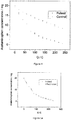
- the figure 2 shows comparison of concentration of AA in the effluent during each 19.6 C of charged applied to the system for both pulsed cleaning and control. It is observed that the reduction of concentration of AA is exponentially decaying for both set of trials.
- the total energy required to oxidise AA completely using the process according to the invention is 36 kWh whereas that of control is 119 kWh.
- the process according to the invention consumes about 3.3 times less energy.
- the figure 4 shows comparison of concentration of paracetamol in the effluent during each 19.6 C of charged applied to the system for both pulsed cleaning and control. It is observed that the reduction of concentration of paracetamol is exponentially decaying for both set of trials.
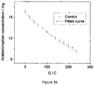
- the figures 5a and 5b show comparison of concentration of paracetamol in the effluent during each 19.6 C of charged applied to the system for both pulsed cleaning and control. It is observed that the reduction of concentration of paracetamol is of exponentially decaying for both set of trials. Table 2 shows comparison of oxidation of paracetamol for both cases. Table 2: Comparison of pulsed trails and control in oxidising paracetamol in effluent. Example 4 trials Percentage reduction of paracetamol Energy consumed (Wh) Energy consumption for 100% oxidation (Wh) Pulsed (invention) 97 % 25 33 Control 57 % 25 82
- the total energy required to oxidise paracetamol completely using the process according to the invention is 33 kWh whereas that of control is 82 kWh.
- the process according to the invention consumes about 2.5 times less energy.
- Example 5 Oxidation of ascorbic acid using different electrode combinations
- AA 20 mg was dissolved in one litre of water and was circulated through the electrolytic cell with a flow rate of 600 m 3 .h -1 .
- BDD was used as working and counter electrodes for electrochemical oxidation of AA and a three-electrode setup (as mention in example 2) was used for quantifying AA.
- the total amount of charged transferred is 99 C for both pulsed and control trials.
- Table 3 shows the percentage reduction in AA concentration when a charge of 99 C was transferred to the system. This experiment elaborated that the pulsed cleaning is applicable also to other electrodes. Table 3: Concentration of AA before and after transfer of 99 C of charge for both pulsed and control trials.
- Electrochemical treatment being an energy-intense process despite attracting a great deal of attention due to the control simplicity, it has been demonstrated in the examples, the process of the invention allows to increase the energy efficiency of cleaning. Contrary to the other electrochemical techniques commonly reported in the literature, the process electrochemical cleaning according to the invention is minimum resource consuming and do not produce any chemical wastes.
Landscapes
- Chemical & Material Sciences (AREA)
- Chemical Kinetics & Catalysis (AREA)
- Electrochemistry (AREA)
- General Chemical & Material Sciences (AREA)
- Life Sciences & Earth Sciences (AREA)
- Hydrology & Water Resources (AREA)
- Engineering & Computer Science (AREA)
- Environmental & Geological Engineering (AREA)
- Water Supply & Treatment (AREA)
- Organic Chemistry (AREA)
- Water Treatment By Electricity Or Magnetism (AREA)
Abstract
The invention relates to a process of electrochemical oxidation of a pollutant in an aqueous electrolyte using a multiple-electrode setup comprising at least a working electrode and at least a counter electrode and applying at least one train of current pulse, said train of current pulse comprises n pulses, n being an integer superior or equal to 2, n being identical or different from one train of current pulse to another,
wherein:
- each train of current pulse comprises positive pulses and may optionally comprise one negative pulse,
- each positive pulse has a different amplitude and/or duration,
- each positive pulse is followed by an off period of time during which the setup is turned off.
wherein:
- each train of current pulse comprises positive pulses and may optionally comprise one negative pulse,
- each positive pulse has a different amplitude and/or duration,
- each positive pulse is followed by an off period of time during which the setup is turned off.
Description
- The present invention is about electrochemical cleaning. In particular, the invention relates to a novel process for electrochemical cleaning of polluted water. This process consists in a specific signal applied to the electrodes in a multiple electrode setup.
- Toxic and non-biodegradable organic pollutants, pathogens and micropollutants in drinking water pose serious health risks, making it an absolute necessity to develop innovative, efficient wastewater treatment techniques and better water management systems. Conventional water treatment processes, such as flocculation (coagulation) and chemical treatment (poly-aluminium chloride, ferric chloride, ferrous sulphate, etc.), produce large quantities of chemical waste products. Ion exchange, activated carbon adsorption and membrane filtration are expensive and require frequent replacement of filters and membranes. These techniques are, therefore, insufficiently adapted to meet the dramatic increase in demand for high-quality water for domestic and industrial purposes. In contrast, the electrochemical disinfection and treatment (electrochemical oxidation) of organic contaminated water has recently gained widespread interest.
- The electrochemical oxidation employing conventional electrodes such as PbO2, Ti/PbO2, SnO2, etc. have low corrosion resistance and low physicochemical stability. Boron-doped diamond electrodes (BDD electrodes), is, currently, the focus of research and development of wastewater treatment because they have superior electroanalytical properties: an extremely wide potential window in aqueous electrolytes (> 3 V), corrosion resistance in aggressive media, morphological and structural stability at high electrical voltage, low adsorption, low base current and biocompatibility. BDD elecrodes are for instance described in Kiran et al. (Journal of the Electrochemical Society, 160 (2) H1-H7 (2013)).
- During electrochemical cleaning, two types of phenomena are occurring: direct anodic oxidation, electrogeneration of active species such as OH* (Hydroxyl radical). OH* can also destroy the microbes. The formation OH* is explained by the following chemical equation (Nasr, B., Abdellatif, G., Cañizares, P., Sáez, C., Lobato, J., & Rodrigo, M. A. (2005), Environmental science & technology, 39(18), 7234-7239):
H2O → OH* + H+ + e-
- OH* generated are oxidants and they oxidize the organic molecule (R) to carbon dioxide and water.
OH* + R → mCO2 + nH2O + e-
- Electrochemical (waste) water treatment technique has undergone rapid development. However, the power consumed for organic pollutant removal has to remain minimal in order to penetrate wide market range, where coagulation and flocculation is still used. Influence of various parameters such as current density, pH, temperature, electrode material and electrolyte affect the efficiency of electrochemical water treatment.
- Electrochemical water treatment is usually performed by passing electric current through the water using suitable electrodes (Kraft, Alexander, Platinum metals review 52.3 (2008): 177-185). The electric current dissociates water and lead to the electrochemical production of disinfecting species, OH*, causing elimination of a broad-range of organic contaminants (Chaplin, Brian P., Environmental Science: Processes & Impacts 16.6 (2014): 1182-1203). SnO2, Ti/SnO2-Sb-Ce, PbO2, Ce-PbO2, boron doped diamond electrodes can be widely applied in water treatment by electrochemical oxidation processes (Lin, Hui, et al., Environmental science & technology, 47.22 (2013): 13039-13046). These electrodes possess superior qualities when considered to other common electrodes such as an inert surface with low adsorption properties, remarkable corrosion stability and an extremely wide potential window in aqueous medium, resulting in the electrochemical production of OH* in much larger extent (Kiran, Raphael, et al., Journal of The Electrochemical Society 160.1 (2013): H67-H73).
- An example of organic pollutants that can be destroyed through electrochemical oxidation include: phenols, chlorophenols, nitrophenols, dyes, surfactants, oil, waste from pulp and paper industry, pathogens, pesticides, insecticides, herbicides, pharmaceutical wastes, micropollutants, etc.
- However, high energy consumption of electrochemical oxidation limits its industrial application. As per the generally accepted mechanism, water is discharged by maintaining anode at potentials above 1.23 V v/s SHE (standard hydrogen electrode). A single current pulse of
current density - Similar protocols (of application of single pulse) were used for electrochemical oxidation of textile dyes (4 to 50 mA.cm-2) (Tsantaki, Eleni, et al., Journal of hazardous materials 207 (2012): 91-96), pharmaceutical effluent (20 to 100 A.cm-2) (Urtiaga, A. M., et al., Desalination 331 (2013): 26-34), oil (1.4 - 1.54 V v/s SHE, current density of 50 mA.cm-2) (Chatzisymeon, E., et al., Journal of Hazardous Materials 167.1 (2009): 268-274, pesticide atrazine (mA.cm-2) (Malpass, G. R. P., et al., Journal of hazardous materials 137.1 (2006): 565-572). Other parameters influencing the oxidation efficiency were also reported in the literature, such as the influence of pH, electrolyte concentration or temperature (De Sucre, V. Smith, and A. P. Watkinson, The Canadian Journal of Chemical Engineering 59.1 (1981): 52-59; Saracco, Guido, et al., Electrochimica Acta 46.2 (2000): 373-380; Martinez-Huitle, Carlos A., and Sergio Ferro., Chemical Society Reviews 35.12 (2006): 1324-1340).
- In contrast with the techniques reported in the prior art, influence of the pulsed current density on the efficiency of electrochemical oxidation has never been investigated. Pulsed electrochemical techniques have been used in electrodeposition, etching, neural stimulation and activation of the electrode (Ghaemi, M., and L. Binder, Journal of power sources 111.2 (2002): 248-254; Liu, Y., et al., Solid state communications 127.8 (2003): 583-588; Negi, Sandeep, et al., Journal of neuroscience methods 186.1 (2010): 8-17, Kiran, Raphael, et al., Journal of The Electrochemical Society 160.1 (2013): H67-H73).
- In Kiran etal. the authors have demonstrated an electrochemical treatment technique where a train of short cathodic and anodic pulses were applied to clean fouled electrodes. This technique is to revive the lost electrochemical properties of a boron doped diamond electrode that has been fouled in organic media or aged in air. The duration of the aforementioned activation is very short (the order of milliseconds) and such a process is not capable of performing water treatment.
- Therefore, there is a need for an electrochemical cleaning process that allows to perform water treatment while consuming less energy than the conventional electrochemical cleaning process.
- The Applicant has developed a novel process, wherein the water treatment energy consumption is decreased by several folds. The process, object of this invention, is a novel, energy efficient electrochemical oxidation process of organic pollutants in aqueous media, based on application of at least one train of positive current pulses, optionally comprising at least one negative pulse, instead of applying a single pulse.
- The applicant has surprisingly observed that the process of the invention allows to oxidise more pollutant or contaminant in water for a same amount of energy spent than a process where a single current pulse or alternate current pulse is applied. In the end, the process according to the invention allows to spend up to several times less energy for the same amount of contaminant oxidised.
- The process of the invention presents the advantages of:
- producing few and even no chemical wastes;
- consuming less energy than usual electrochemical cleaning systems.
- In one embodiment, the invention relates to a process of electrochemical oxidation of a pollutant in an aqueous electrolyte using a multiple-electrode setup comprising at least a working electrode and at least a counter electrode and applying at least one train of current pulse, said train of current pulse comprises n pulses, n being an integer superior or equal to 2, n being identical or different from one train of current pulse to another,
wherein: - each train of current pulse comprises positive pulses and may optionally comprise at least one negative pulse,
- each positive pulse has a different amplitude and/or duration,
- each positive pulse is followed by an off period of time during which the setup is turned off.
- When the process comprises more than one train of current pulse, the trains of current pulse are identical or different.
- The is no limitation for the number of trains of current pulse, the skilled artisan will apply as many trains of current pulse that are necessary to oxidize the required amount of pollutant.
- In one embodiment, the process comprises more than 2 trains of current pulse, preferably more than 500 and more preferably more than 1000.
- In one embodiment, each off period of time during which the setup is turned off has a different duration.
- In one embodiment, the at least one train of current pulse is either descending, ascending or unsorted train of current pulse wherein:
- o in a descending train of current pulse, the amplitude of the positive pulses decreases from one pulse to another in function of time, the duration of the positive pulses decreases from one pulse to another in function of time and/or the duration of the off periods of time between two positive pulses decreases from one off period to another in function of time,
- o in an ascending train of current pulse, the amplitude of the positive pulses increases from one pulse to another in function of time, the duration of the positive pulses increases from one pulse to another in function of time and/or the duration of the off periods of time between two positive pulses increases from one off period to another in function of time,
- o in an unsorted train of current pulse, the amplitude of the positive pulses increases or decreases from one pulse to another in function of time, the duration of the positive pulses increases or decreases from one pulse to another in function of time and/or the duration of the off periods of time between two positive pulses increases or decreases from one off period to another in function of time.
- In the context of the invention, a power supply can either be from a voltage source and/or a current source. The process of the invention comprises at least one train of current pulse. The skilled person would at ease understand how to reproduce the process of the invention with trains of voltage or potential pulses.
- It is meant by "pulse", a short-term variation of a physical magnitude (voltage. current, etc.) with a return to the initial state. Within the scope of the invention, "pulse" refers to a short voltage or current variation for a total time from 100 milliseconds to 600 seconds, followed by a return to the initial state (usually with amplitude equal to zero) of the voltage or current value. The "amplitude" of a pulse refers to the maximum value of the anodic or cathodic current (or voltage) reached during an anodic or cathodic current (or voltage) pulse relative to a base line, usually equal to zero.
- It is meant by "positive pulse", a pulse for which the amplitude relative to the base line increases and returns to the base line after a certain duration, from 100 milliseconds to 600 seconds. A "negative pulse" may be considered as being a wave for which the amplitude reduces relative to the base line and returns to the base line after a duration, from 100 milliseconds to 300 seconds.
- It is meant by "aqueous electrolyte", an aqueous conducting solution. In one embodiment, the electrolyte is a salt, an acid or a base dissolved in the solution. In one embodiment, the electrolyte is the pollutant.
- It is meant by "pollutant", an organic substance that is dissolved in or in mixture with the aqueous electrolyte. In an embodiment, the pollutant may further contain inorganic substance(s).
- In the context of the invention, a pollutant is considered to be the molecule or compound that will be oxidised during the process of the invention.
- An "unsorted train of current pulse" according to the invention can be understood as a random ascending or a random descending train of current pulse. It means that each single positive pulse of the random train of current pulse has a different amplitude and/or duration.
- In one embodiment, in the at least one train of current pulse the amplitude of the positive pulses increases or decreases by 5 to 30 %, preferably by 5 to 20 % and more preferably by 5 to 15 % from one pulse to another in function of time.
- In one embodiment, in the at least one train of current pulse the amplitude of the positive pulses increases or decreases by 10 % from one pulse to another in function of time.
- In one embodiment, in the at least one train of current pulse the duration of the positive pulses increases or decreases by 5 to 30 %, preferably by 5 to 20 % and more preferably by 5 to 15 % from one pulse to another in function of time.
- In one embodiment, in the at least one train of current pulse the duration of the positive pulses increases or decreases by 10 % from one pulse to another in function of time.
- In one embodiment, in the at least one train of current pulse the duration of the off periods of time between two positive pulses increases or decreases by 5 to 30 %, preferably by 5 to 20 % and more preferably by 5 to 15 % from one off period to another in function of time.
- In one embodiment, in the at least one train of current pulse the duration of the off periods of time between two positive pulses increases or decreases by 10 % from one off period to another in function of time.
- In one embodiment, the duration of the first off period of time is comprised between 85 and 95 %, preferably 90 % of the duration of the first positive pulse of the at least one train of current pulse.
- In one embodiment, each positive pulse of the at least one train of current pulse has an amplitude ≥ 0.1 mA.cm-2.
- In one embodiment, each positive pulse of the at least one train of current pulse has a amplitude ≥ 1 mA.cm-2.
- In one embodiment, each positive pulse of the at least one train of current pulse has a duration ≥ 100 ms.
- In one embodiment, each positive pulse of the at least one train of current pulse has a duration ≥ 1 s.
- In one embodiment, in the at least one train of current pulse, the amplitude of the first positive pulse is comprised between 1 and 50 mA.cm-2, preferably between 5 and 25 mA.cm-2 and more preferably between 10 and 20 mA.cm-2 and the amplitude of pulses is defined such as the amplitude of a positive pulse m is equal to 70 to 95 % preferably 80 to 95 % and more preferably 85 to 95 % of the amplitude of a positive pulse m-1, m being an integer and 1 ≤ m ≤ n.
- In one embodiment, in the at least one train of current pulse, the amplitude of the first positive pulse is comprised between 10 and 15 mA.cm-2.
- In one embodiment, in the at least one train of current pulse, the amplitude of the first positive pulse is 13.3 mA.cm-2.
- In one embodiment, in the at least one train of current pulse, the duration of the first positive pulse is comprised between 1 and 600 seconds, preferably between 2 and 20 seconds, more preferably between 3 and 10 seconds and the duration of positive pulses is defined such as the duration of a positive pulse m is equal to 70 to 95 % preferably 80 to 95 % and more preferably 85 to 95 % of the duration of a positive pulse m-1, m being an integer and 1 ≤ m ≤ n.
- In one embodiment, wherein in the at least one train of current pulse, the duration of the first positive pulse is comprised between 3 and 8 seconds.
- In one embodiment, wherein in the at least one train of current pulse, the duration of the first positive pulse is 6 seconds.
- In one embodiment, in the at least one train of current pulse, the duration of the first off period of time is comprised between between 1 and 600 seconds, preferably between 2 and 20 seconds, more preferably between 3 and 10 seconds and the duration of the off periods of time is defined such as the duration of the off period of time p is equal to 70 to 95 % preferably 80 to 95 % and more preferably 85 to 95 % of the the off period of time p-1, p being an integer and 1 ≤ p ≤ n.
- In one embodiment, in the at least one train of current pulse, the duration of the first off period of time is comprised between 3 and 8 seconds.
- In one embodiment, in the at least one train of current pulse, the duration of the first off period of time is 6 seconds, preferably 5.4 seconds.
- In one embodiment, in the at least one train of current pulse, the amplitude of the first positive pulse is comprised between 1 and 30 mA.cm-2, preferably between 1 and 25 mA.cm-2 and more preferably between 1 and 10 mA.cm-2 and the amplitude of positive pulses is defined such as the amplitude of a positive pulse m-1 is equal to 70 to 95 % preferably 80 to 95 % and more preferably 85 to 95 % of the amplitude of a positive pulse m, m being an integer and 1 ≤ m ≤ n.
- In one embodiment, in the at least one train of current pulse, the duration of the first positive pulse is comprised between 1 to 600 seconds, preferably between 1 and 20 seconds, more preferably between 31 and 10 seconds and the duration of positive pulses is defined such as the duration of a positive pulse m-1 is equal to 70 to 95 %, preferably 80 to 95 % and more preferably 85 to 95 % of the duration of a positive pulse m, m being an integer and 1 ≤ m ≤ n.
- In one embodiment, in the at least one train of current pulse, the duration of the first off period of time is comprised between between 1 and 600 seconds, preferably between 1 and 20 seconds, more preferably between 1 and 10 seconds and the duration of the off periods of time is defined such as the duration of the off period of time p-1 is equal to 70 to 95 % preferably 80 to 95 % and more preferably 85 to 95 % of the off period of time p, p being an integer and 1 ≤ p ≤ n.
- In one embodiment, the duration of each train of current pulse is comprised between 30 and 5000 seconds, preferably between 40 and 200 seconds and more preferably between 50 and 100 seconds.
- In one embodiment, the duration of each train of current pulse is comprised between 50 and 80 seconds, prefereably 60 seconds.
- In one embodiment, the total off period of time in the at least one train of current pulse is more than 1 % of the total duration of the at least one train of current pulse, preferably more than 10 % and more preferably more than 50 %.
- In one embodiment, the sum of the durations of the pulses in the at least one train of current pulse is more than 99 % of the total duration of said train of current pulse, preferably more than 90 % and more preferably more than 50 %.
- In one embodiment, the at least one negative pulse is the last pulse of the at least one train of current pulse.
- In the process, according to the invention, the number of negative pulses is always smaller than the number of positive pulses. In a train of current pulse, the number of negative pulses is always smaller than the number of positive pulses.
- In one embodiment, in each train of current pulse, the ratio: (number of negative pulses)/(number of positive pulses) is ≤ 0.5, preferably ≤ 0.3 and more preferably ≤ 0.15.
- In one embodiment, each train of current pulse comprises a negative pulse, preferably the negative pulse is the last pulse of each train of current pulse.
- In one embodiment, the amplitude of the negative pulse is comprised between 1 and 50 mA.cm-2, preferably between 5 and 30 mA.cm-2 and more preferably between 5 and 15 mA.cm-2.
- In one embodiment, the amplitude of the negative pulse is 10 mA.cm-2.
- In one embodiment, the duration of the negative pulse is comprised between 0.01 and 50 s, preferably between 0.1 and 10 sand more preferably between 0.02 and 1 s.
- In one embodiment, the duration of the negative pulse is 0.5 s.
- In one embodiment, the pulses shape is periodic or aperiodic, preferably periodic and of triangle, square, sinusoidal, saw tooth or wave shape and more preferably periodic and of square shape.
- In one embodiment, the positive pulses shape is periodic or aperiodic, preferably periodic and of triangle, square, sinusoidal, saw tooth or wave shape and more preferably periodic and of square shape.
- In one embodiment, the negative pulses shape is periodic or aperiodic, preferably periodic and of triangle, square, sinusoidal, saw tooth or wave shape and more preferably periodic and of square shape.
- The positive pulses shape and the negative pulses shape is identical or different.
- In one embodiment, the amplitude of the pulses in the at least one train of current pulse is comprised between 0.1 and 1000 mA.cm-2, preferably between 1 and 100 mA.cm-2, and more preferably between 5 and 50 mA.cm-2.
- In one embodiment, a train of voltage pulse is applied and the potential of the pulses in the at least one train of current pulse is comprised between 0.1 and 100 V, preferably between 0.5 and 50 V, and more preferably between 1 and 24 V.
- All the embodiments described for the process comprising at least one train of current pulse are applicable to the process comprising at least one train of voltage pulse.
- In one embodiment, the number n of pulses of the at least one train of current pulse is comprised between 2 and 10000, preferably between 2 and 1000, more preferably between 2 and 100 and in a favoured embodiment between 2 and 20.
- In one embodiment, the number n of pulses of the at least one train of current pulse is comprised between 5 and 15, preferably between 5 and 10.
- In one embodiment, wherein the number n of pulses of the at least one train of current pulse is 7.
- In one embodiment, each train of current pulse consist in n-1 positive pulses, n-1 off periods of time during which the setup is turned off and one negative pulse, each positive pulse is followed by an off period of time and the negative pulse is the last pulse of each train of current pulse.
- In one embodiment, each train of current pulse is a descending train of current pulse and each train of current pulse consist in n-1 positive pulses, n-1 off periods of time during which the setup is turned off and one negative pulse, each positive pulse is followed by an off period of time and the negative pulse is the last pulse of each train of current pulse.
- In one embodiment, each train of current pulse is a descending train of current pulse and each train of current pulse consist in n-1 positive pulses, n-1 off periods of time during which the setup is turned off and one negative pulse, each positive pulse is followed by an off period of time, the negative pulse is the last pulse of each train of current pulse, n is comprised between 5 and 15 and the amplitude of the first pulse is comprised between 10 and 20 mA.cm-2.
- In one embodiment, the process comprises more than 10 trains of current pulse, preferably more than 100, each train of current pulse is a descending train of current pulse and each train of current pulse consist in n-1 positive pulses, n-1 off periods of time during which the setup is turned off and one negative pulse, each positive pulse is followed by an off period of time, the negative pulse is the last pulse of each train of current pulse, n is comprised between 5 and 15 and the amplitude of the first pulse is comprised between 10 and 20 mA.cm-2.
- In one embodiment, the process comprises more than 600 trains of current pulse, each train of current pulse is a descending train of current pulse and each train of current pulse consist in n-1 positive pulses, n-1 off periods of time during which the setup is turned off and one negative pulse, each positive pulse is followed by an off period of time and the negative pulse is the last pulse of each train of current pulse, n is between 5 and 10 and the amplitude of the first pulse is between 10 and 15 mA.cm-2.
- According to the invention, the setup is a multiple-electrode setup. When a multiple-electrode setup is used to oxidize the organic pollutant, there can be one or more working electrode and they can be current source through which current of same or different amplitude flows, there can be one or more than one counter electrode and they can be current sink through which current of same or different amplitude flows. Preferably, the setup used to oxidize organic impurities is a two-electrode setup (comprising a working and a counter electrode). The working electrode is the current source (organic pollutants are oxidized in the vicinity of the working electrode) and the counter electrode is the current sink.
- In one embodiment, the setup used to oxidize organic impurities is a three-electrode setup (comprising a working, a counter and a reference electrode). The working electrode is the current source (organic pollutants are oxidized in the vicinity of the working electrode) and the counter electrode is the current sink and the reference electrode is held at constant potential.
- In one embodiment, the working electrode is water treatment electrode material.
- In one embodiment, the counter electrode is water treatment electrode material.
- In one embodiment, the working electrode is chosen from the group comprising boron doped diamond, diamond like carbon, graphite, Ti, TiO2, Pt, Pb, PbO2, SnO2, their alloys or combination of these materials electrodes.
- In one embodiment, the counter electrode is chosen from the group comprising boron doped diamond, stainless steel, platinum, Ti, TiO2, Au, their alloys or of combination of these materials electrodes.
- In one embodiment, the reference electrode is a chosen from the group comprising standard hydrogen electrode, normal hydrogen electrode, reversible hydrogen electrode, saturated calomel electrode, copper-copper(II) sulphate electrode and silver chloride electrode.
- In one embodiment, the working electrode is a boron doped diamond electrode and the counter electrode is chosen from the group consisting of stainless steel, platinum, Ti, TiO2, Au, their alloys or of combination of these materials electrodes.
- In one embodiment, the working electrode is chosen from the group consisting of diamond like carbon, graphite, Ti, TiO2, Pt, Pb, PbO2, SnO2, their alloys or combination of these materials electrodes and the counter electrode is a boron doped diamond electrode.
- In a preferred embodiment, the working electrode a boron doped diamond electrode and the counter electrode is a boron doped diamond electrode.
- In one embodiment, the dimension of the electrodes is comprised between 0.01 and 100,000 cm2, preferably between 1 and 1,000 cm2 and more preferably between 1 and 500 cm2.
- In one embodiment, the dimension of the electrodes is comprised between 1 and 200 cm2, preferably between 50 and 150 cm2, more preferably between 80 and 120 and most preferably 100 cm2.
- Process according to any of preceeding claims, wherein the working and counter electrodes are separated by a distance of between 0.01 and 10,000 mm, preferably 0.1 and 100 mm and more preferably 0.5 and 10 mm.
- In one embodiment, the working and counter electrodes are separated by a distance of between 1 and 8 mm, preferably 1 and 5 mm and more preferably 1 and 3 mm.
- In one embodiment, the electrolyte is the pollutant.
- In one embodiment, the pollutant is an organic molecule, preferably chosen in the group comprising phenols, chlorophenols, nitrophenols, dyes, surfactants, oil, waste from pulp and paper industry, pathogens, pesticides, insecticides, herbicides, pharmaceutical wastes, micropollutants.
- In one embodiment, the invention relates to a clean water obtained according to the process of the invention,
- In one embodiment, the clean water contains less than 20 % of pollutant compared to the water before being cleaned, preferably less than 10 %.
- The invention also relates to the multiple electrode setup wherein the at least one train of current pulse is applied.
-
-
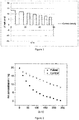
Figure 1 shows a typical descending pulse train that is applied to the working electrodes for the oxidation of organic pollutant, where J is the current density in mA.cm-2, t is the time in seconds. -
Figure 2 shows the concentration of ascorbic acid (AA) in mg versus charge (Q) in coulombs transferred to the working electrode during the oxidation process of example 3. The pulsed trial uses the pulsing conditions mentioned in example 2 and control uses single pulse for the entire operation. -
Figures 3a and 3b represent the concentration of ascorbic acid (AA) in mg versus charge (Q) in coulombs transferred to the working electrode during the oxidation process of example 3 for both pulsed (3a) and control trials (3b) along with fitted curve. -
Figure 4 represents the concentration of paracetamol in mg versus charge (Q) in coulombs transferred to the working electrode during the oxidation process of example 4. The pulsed trial uses the pulsing conditions mentioned in example 2 and control uses single pulse for the entire operation. -
Figures 5a and5b show the concentration of paracetamol in mg versus charge (Q) in coulombs transferred to the working electrode during the oxidation process of example 4 for both pulsed (5a) and control trials (5b) along with fitted curve. - The following examples illustrate, in a non-limitative way the invention.
- The electrochemical oxidations were conducted using an electrolytic flow cell under applying a train of current/voltage pulse. Distilled water containing organic compounds (ascorbic acid and paracetamol solutions) was circulated through the electrolytic cell by means of a pump working with a flow rate of 600 m3.h-1. BDD, TiO2 and stainless steel were used as working and counter electrodes. Both electrodes were of circular disks with area of 75 cm2 and the distance between the cathode and anode is kept 1 mm.
- A two-electrode setup consisting of the working electrode (BDD, TiO2 or stainless steel) and counter electrode (BDD, TiO2 or stainless steel) was employed for the electrochemical oxidation of organic compounds. In order to simulate organic pollutants, two organic compounds were used: ascorbic acid (AA) and paracetamol. Their solutions were prepared daily by dissolving 20 mg of respective compound in one litre of water.
- The oxidation process consists of applying a sequence of trains of current pulse of finite amplitude for a finite duration on the working electrode.
- A train of current pulse contains a positive pulse of amplitude 13.3 mA.cm-2 and a duration of 6 seconds (s) and the system is turned off for 5.4 s, followed by a positive pulse of
amplitude 12 mA.cm-2 and a duration of 5.4 s and the system is turned off for 4.9 s, followed by a positive pulse of amplitude 10.8 mA.cm-2 and a duration of 4.9 s and the system is turned off for 4.4 s, followed by a positive pulse of amplitude 9.7 mA.cm-2 and a duration of 4.4 s and the system is turned off for 3.9 s, followed by a positive pulse of amplitude 8.7 mA.cm-2 and a duration of 3.9 s and the system is turned off for 3.5 s, followed by a positive pulse of amplitude 7.9 mA.cm-2 and a duration of 3.5 s and the system is turned off for 3.2 s, followed by a positive pulse of amplitude 7.1 mA.cm-2 and a duration of 3.2 s and the system is turned off for 2.9 s, followed by a negative pulse ofamplitude 10 mA.cm-2 and a duration of 0.5 s. - The above train of current pulse is repeated 720 times.
- The control of the experiment is the same system with application of a single current pulse of amplitude 13.3 mA.cm-2 for a duration of 297 minutes, which corresponds to the same energy spent to oxidise 20 mg of organic compound dissolved in one litre of water. However, the pulsed cleaning and control experiment resulted in different yield as depicted in Table 1.
- The oxidation process is paused for a duration of 5 minutes, at an interval when the total charged applied is 19.8 C.cm-2, in order to measure the concentration of organic compound. The concentration of organic compound is measured according to cyclic voltammetry.
- The concentration of organic compounds was quantified using cyclic voltammetry (CV) after each hour of electrochemical oxidation. A three-electrode setup consisting of BDD as the working electrode, platinum as the counter electrode and silver chloride as the reference electrode was employed for the CV characterization.
- This standard procedure is described in Kim et al., Biosensors and Bioelectronics 25.10 (2010): 2366-2369 or Masawat, Prinya, et al., Talanta 58.6 (2002): 1221-1234.
- Oxidation peaks were obtained from CV at scan rate = 200 mV.s-1, where the working electrode was scanned from -0.5 V to 2 V vs AgCI.
- 20 mg of AA was dissolved in one litre of water and was circulated through the electrolytic cell with a flow rate of 600 m3 h-1. BDD was used as working and counter electrodes for electrochemical oxidation of AA and a three-electrode setup (as mention in example 2) was used for quantifying AA.
- The oxidation was performed according to example 1.
- The
figure 2 shows comparison of concentration of AA in the effluent during each 19.6 C of charged applied to the system for both pulsed cleaning and control. It is observed that the reduction of concentration of AA is exponentially decaying for both set of trials.Figures 3a and 3b show the exponential fit of both pulsed and control trials. The equation of fit for pulsed and control trials are y = -0.4 + 20.2 e -x/78.9, R2 = 99.94 % and y = -0.7 + 20.4 e -x/292.9, R2 =99.63 % respectively. - The total energy spent for the oxidation of AA is 28 kWh. For the same amount of energy, using the pulsed cleaning 98 % of AA was oxidation, whereas only 59% of AA was oxidised in the control trial. Table 1 shows the difference in percentage reduction of AA for each of the trial.
Table 1: Comparison of pulsed trails and control in oxidating ascorbic acid in effluent. Example 3 trials Percentage reduction of AA Energy consumed (Wh) Energy consumption for 100% oxidation (Wh) Pulsed (invention) 98% 28 36 Control 59% 28 119 - As per the fitting parameters, the total energy required to oxidise AA completely using the process according to the invention is 36 kWh whereas that of control is 119 kWh. The process according to the invention consumes about 3.3 times less energy.
- 20 mg of paracetamol was dissolved in one litre of water and was circulated through the electrolytic cell with a flow rate of 600 m3.h-1. BDD was used as working and counter electrodes for electrochemical oxidation of paracetamol and a three-electrode setup (as mention in example 2) was used for quantifying paracetamol.
- The oxidation was performed according to example 1.
- The
figure 4 shows comparison of concentration of paracetamol in the effluent during each 19.6 C of charged applied to the system for both pulsed cleaning and control. It is observed that the reduction of concentration of paracetamol is exponentially decaying for both set of trials.Figure 5 shows the exponential fit of both pulsed and control trials. The equation of fit for pulsed and control trials are y = -0.6 + 20.7 e -x/88.8, R2 = 99.45 % and y = -2.3 + 21.6 e -x/339.7 R2 = 99.92 % respectively. - The
figures 5a and5b show comparison of concentration of paracetamol in the effluent during each 19.6 C of charged applied to the system for both pulsed cleaning and control. It is observed that the reduction of concentration of paracetamol is of exponentially decaying for both set of trials. Table 2 shows comparison of oxidation of paracetamol for both cases.Table 2: Comparison of pulsed trails and control in oxidising paracetamol in effluent. Example 4 trials Percentage reduction of paracetamol Energy consumed (Wh) Energy consumption for 100% oxidation (Wh) Pulsed (invention) 97 % 25 33 Control 57 % 25 82 - As per the fitting data, the total energy required to oxidise paracetamol completely using the process according to the invention is 33 kWh whereas that of control is 82 kWh. The process according to the invention consumes about 2.5 times less energy.
- 20 mg of AA was dissolved in one litre of water and was circulated through the electrolytic cell with a flow rate of 600 m3.h-1. BDD was used as working and counter electrodes for electrochemical oxidation of AA and a three-electrode setup (as mention in example 2) was used for quantifying AA. The total amount of charged transferred is 99 C for both pulsed and control trials.
- The experiment was repeated using TiO2 as working and counter electrode, as well as using stainless steel. Table 3 shows the percentage reduction in AA concentration when a charge of 99 C was transferred to the system. This experiment elaborated that the pulsed cleaning is applicable also to other electrodes.
Table 3: Concentration of AA before and after transfer of 99 C of charge for both pulsed and control trials. Electrode Cleaning Before After % difference BDD Pulsed (invention) 19.73 ± 0.06 5.53 ± 0.25 72% BDD Control 19.93 ± 0.15 13.87 ± 0.12 30 % Stainless steal Pulsed (invention) 19.73 ± 0.12 16.80 ± 0.46 15 % Stainless steal Control 20.06 ± 0.21 18.60 ± 0.44 7 % TiO2 Pulsed (invention) 19.76 ± 0.31 14.03 ± 0.68 29 % TiO2 Control 20.03 ± 0.57 17.03 ± 0.32 15 % - Electrochemical treatment being an energy-intense process despite attracting a great deal of attention due to the control simplicity, it has been demonstrated in the examples, the process of the invention allows to increase the energy efficiency of cleaning. Contrary to the other electrochemical techniques commonly reported in the literature, the process electrochemical cleaning according to the invention is minimum resource consuming and do not produce any chemical wastes.
Claims (15)
- Process of electrochemical oxidation of a pollutant in an aqueous electrolyte using a multiple-electrode setup comprising at least a working electrode and at least a counter electrode and applying at least one train of current pulse, said train of current pulse comprises n pulses, n being an integer superior or equal to 2, n being identical or different from one train of current pulse to another,
wherein,- each train of current pulse comprises positive pulses and may optionally comprise at least one negative pulse,- each positive pulse has a different amplitude and/or duration,- each positive pulse is followed by an off period of time during which the setup is turned off, preferably each off period of time during which the setup is turned off has a different duration,- the trains of current pulse are identical or different. - Process according to claim 1 or 2, wherein the at least one train of current pulse is either descending, ascending or unsorted train of current pulse wherein:o in a descending train of current pulse, the amplitude of the positive pulses decreases from one pulse to another in function of time, the duration of the positive pulses decreases from one pulse to another in function of time and/or the duration of the off periods of time between two positive pulses decreases from one off period to another in function of time,o in an ascending train of current pulse, the amplitude of the positive pulses increases from one pulse to another in function of time, the duration of the positive pulses increases from one pulse to another in function of time and/or the duration of the off periods of time between two positive pulses increases from one off period to another in function of time,o in an unsorted train of current pulse, the amplitude of the positive pulses increases or decreases from one pulse to another in function of time, the duration of the positive pulses increases or decreases from one pulse to another in function of time and/or the duration of the off periods of time between two positive pulses increases or decreases from one off period to another in function of time.
- Process according to claim 1, wherein in the at least one train of current pulse the amplitude of the positive pulses increases or decreases by 5 to 30 %, preferably by 5 to 20 % and more preferably by 5 to 15 % from one pulse to another in function of time.
- Process according to claim 1, wherein in the at least one train of current pulse the duration of the positive pulses increases or decreases by 5 to 30 %, preferably by 5 to 20 % and more preferably by 5 to 15 % from one pulse to another in function of time.
- Process according to claim 1, wherein in the at least one train of current pulse the duration of the off periods of time between two positive pulses increases or decreases by 5 to 30 %, preferably by 5 to 20 % and more preferably by 5 to 15 % from one off period to another in function of time.
- Process according to claim 1, wherein in the at least one train of current pulse, the amplitude of the first positive pulse is comprised between 1 and 50 mA.cm-2, preferably between 5 and 25 mA.cm-2 and more preferably between 10 and 20 mA.cm-2 and the amplitude of pulses is defined such as the amplitude of a positive pulse m is equal to 70 to 95 % preferably 80 to 95 and more preferably 85 to 95 of the amplitude of a positive pulse m-1, m being an integer and 1 ≤ m ≤ n.
- Process according to claim 1, wherein in the at least one train of current pulse, the duration of the first positive pulse is comprised between 1 and 600 seconds, preferably between 2 and 20 seconds, more preferably between 3 and 10 seconds and the duration of positive pulses is defined such as the duration of a positive pulse m is equal to 70 to 95 % preferably 80 to 95 and more preferably 85 to 95 of the duration of a positive pulse m-1, m being an integer and 1 ≤ m ≤ n.
- Process according to claim 1, wherein in the at least one train of current pulse, the duration of the first off period of time is comprised between between 1 and 600 seconds, preferably between 2 and 20 seconds, more preferably between 3 and 10 seconds and the duration of the off periods of time is defined such as the duration of the off period of time p is equal to 70 to 95 % preferably 80 to 95 % and more preferably 85 to 95 % of the the off period of time p-1, p being an integer and 1 ≤ p ≤ n.
- Process according to claim 1, wherein the duration of each train of current pulse is comprised between 30 and 5000 seconds, preferably between 40 and 200 seconds and more preferably between 50 and 100 seconds.
- Process according to claim 1, wherein each train of current pulse comprises a negative pulse, preferably the negative pulse is the last pulse of each train of current pulse, the amplitude of the negative pulse is comprised between 1 and 50 mA.cm-2, preferably between 5 and 30 mA.cm-2 and more preferably between 5 and 15 mA.cm-2 and the duration of the negative pulse is comprised between 0.01 and 50 s, preferably between 0.1 and 10 sand more preferably between 0.02 and 1 s.
- Process according to claim 1, wherein the pulses shape is periodic or aperiodic, preferably periodic and of triangle, square, sinusoidal, saw tooth or wave shape and more preferably periodic and of square shape.
- Process according to claim 1, wherein the number n of pulses of the at least one train of current pulse is comprised between 2 and 10000, preferably between 2 and 1000, more preferably between 2 and 100 and in a favoured embodiment between 2 and 20.
- Process according to the preceeding claim, wherein the working electrode is chosen from the group comprising boron doped diamond, diamond like carbon, graphite, Ti, TiO2, Pt, Pb, PbO2, SnO2, their alloys or combination of these materials electrodes, preferably the working electrode is a boron doped diamond electrode, and the counter electrode is chosen from the group comprising boron doped diamond, stainless steel, platinum, Ti, TiO2, Au, their alloys or of combination of these materials electrodes, preferably the counter electrode is a boron doped diamond electrode.
- Process according to claim 1, wherein the pollutant is an organic molecule, preferably chosen in the group comprising phenols, chlorophenols, nitrophenols, dyes, surfactants, oil, waste from pulp and paper industry, pathogens, pesticides, insecticides, herbicides, pharmaceutical wastes, micropollutants.
- A clean water obtained according to the process of any preceeding claims, preferably said clean water contains less than 20 % of pollutant compared to the water before being cleaned, preferably less than 10 %.
Priority Applications (1)
| Application Number | Priority Date | Filing Date | Title |
|---|---|---|---|
| EP17305040.2A EP3348521A1 (en) | 2017-01-12 | 2017-01-12 | Process of electrochemical oxidation |
Applications Claiming Priority (1)
| Application Number | Priority Date | Filing Date | Title |
|---|---|---|---|
| EP17305040.2A EP3348521A1 (en) | 2017-01-12 | 2017-01-12 | Process of electrochemical oxidation |
Publications (1)
| Publication Number | Publication Date |
|---|---|
| EP3348521A1 true EP3348521A1 (en) | 2018-07-18 |
Family
ID=57868189
Family Applications (1)
| Application Number | Title | Priority Date | Filing Date |
|---|---|---|---|
| EP17305040.2A Withdrawn EP3348521A1 (en) | 2017-01-12 | 2017-01-12 | Process of electrochemical oxidation |
Country Status (1)
| Country | Link |
|---|---|
| EP (1) | EP3348521A1 (en) |
Cited By (3)
| Publication number | Priority date | Publication date | Assignee | Title |
|---|---|---|---|---|
| CN109060911A (en) * | 2018-09-12 | 2018-12-21 | 南昌航空大学 | A kind of electrode modified material siliver chromate/graphene oxide preparation method of detectable 4- nitrophenol |
| WO2020085987A1 (en) * | 2018-10-26 | 2020-04-30 | Safe Water Scandinavia Ab | Method and arrangement for treating water in a pool |
| CN115464546A (en) * | 2021-05-25 | 2022-12-13 | 株式会社电装 | Surface treatment equipment and surface treatment method for SiC substrate |
Citations (4)
| Publication number | Priority date | Publication date | Assignee | Title |
|---|---|---|---|---|
| EP0060193A1 (en) * | 1981-03-06 | 1982-09-15 | Claude Freyne | Water treatment device using electrical impulses of a variable current strength |
| EP0468478A2 (en) * | 1990-07-26 | 1992-01-29 | House Food Industrial Co., Ltd. | Method for sterilizing an aqueous medium |
| EP2560921A1 (en) * | 2010-04-22 | 2013-02-27 | Periso SA | Method and device for treatment of water against the formation of bacteria and algae |
| US20150247248A1 (en) * | 2014-03-02 | 2015-09-03 | Johannes A. Thomassen | Apparatus, system, and method for a dynamic rotational electrochemical reactor |
-
2017
- 2017-01-12 EP EP17305040.2A patent/EP3348521A1/en not_active Withdrawn
Patent Citations (4)
| Publication number | Priority date | Publication date | Assignee | Title |
|---|---|---|---|---|
| EP0060193A1 (en) * | 1981-03-06 | 1982-09-15 | Claude Freyne | Water treatment device using electrical impulses of a variable current strength |
| EP0468478A2 (en) * | 1990-07-26 | 1992-01-29 | House Food Industrial Co., Ltd. | Method for sterilizing an aqueous medium |
| EP2560921A1 (en) * | 2010-04-22 | 2013-02-27 | Periso SA | Method and device for treatment of water against the formation of bacteria and algae |
| US20150247248A1 (en) * | 2014-03-02 | 2015-09-03 | Johannes A. Thomassen | Apparatus, system, and method for a dynamic rotational electrochemical reactor |
Non-Patent Citations (20)
| Title |
|---|
| CHAPLIN; BRIAN P., ENVIRONMENTAL SCIENCE: PROCESSES & IMPACTS, vol. 16.6, 2014, pages 1182 - 1203 |
| CHATZISYMEON, E. ET AL., JOURNAL OF HAZARDOUS MATERIALS, vol. 167.1, 2009, pages 268 - 274 |
| DE SUCRE; V. SMITH; A. P. WATKINSON, THE CANADIAN JOURNAL OF CHEMICAL ENGINEERING, vol. 59.1, 1981, pages 52 - 59 |
| GHAEMI, M.; L. BINDER, JOURNAL OF POWER SOURCES, vol. 111.2, 2002, pages 248 - 254 |
| JUNJUN WEI ET AL: "Electrochemical oxidation of phenol at boron-doped diamond electrode in pulse current mode", ELECTROCHIMICA ACTA, ELSEVIER SCIENCE PUBLISHERS, BARKING, GB, vol. 56, no. 15, 1 April 2011 (2011-04-01), pages 5310 - 5315, XP028374321, ISSN: 0013-4686, [retrieved on 20110412], DOI: 10.1016/J.ELECTACTA.2011.04.006 * |
| KIM ET AL., BIOSENSORS AND BIOELECTRONICS, vol. 25.10, 2010, pages 2366 - 2369 |
| KIRAN ET AL., JOURNAL OF THE ELECTROCHEMICAL SOCIETY, vol. 160, no. 2, 2013, pages H1 - H7 |
| KIRAN; RAPHAEL ET AL., JOURNAL OF THE ELECTROCHEMICAL SOCIETY, vol. 160.1, 2013, pages H67 - H73 |
| KRAFT; ALEXANDER, PLATINUM METALS REVIEW, vol. 52.3, 2008, pages 177 - 185 |
| LIN; HUI ET AL., ENVIRONMENTAL SCIENCE & TECHNOLOGY, vol. 47.22, 2013, pages 13039 - 13046 |
| LIU, Y. ET AL., SOLID STATE COMMUNICATIONS, vol. 127.8, 2003, pages 583 - 588 |
| MALPASS, G. R. P. ET AL., JOURNAL OF HAZARDOUS MATERIALS, vol. 137.1, 2006, pages 565 - 572 |
| MARTINEZ-HUITLE; CARLOS A.; SERGIO FERRO., CHEMICAL SOCIETY REVIEWS, vol. 35.12, 2006, pages 1324 - 1340 |
| MASAWAT; PRINYA ET AL., TALANTA, vol. 58.6, 2002, pages 1221 - 1234 |
| NASR, B.; ABDELLATIF, G.; CANIZARES, P.; SAEZ, C.; LOBATO, J.; RODRIGO, M. A, ENVIRONMENTAL SCIENCE & TECHNOLOGY, vol. 39, no. 18, 2005, pages 7234 - 7239 |
| NEGI; SANDEEP ET AL., JOURNAL OF NEUROSCIENCE METHODS, vol. 186.1, 2010, pages 8 - 17 |
| SARACCO; GUIDO ET AL., ELECTROCHIMICA ACTA, vol. 46.2, 2000, pages 373 - 380 |
| TSANTAKI; ELENI ET AL., JOURNAL OF HAZARDOUS MATERIALS, vol. 207, 2012, pages 91 - 96 |
| URTIAGA, A. M. ET AL., DESALINATION, vol. 331, 2013, pages 26 - 34 |
| ZHU; XIUPING; JINREN NI; PENG LAI, WATER RESEARCH, vol. 43.17, 2009, pages 4347 - 4355 |
Cited By (4)
| Publication number | Priority date | Publication date | Assignee | Title |
|---|---|---|---|---|
| CN109060911A (en) * | 2018-09-12 | 2018-12-21 | 南昌航空大学 | A kind of electrode modified material siliver chromate/graphene oxide preparation method of detectable 4- nitrophenol |
| WO2020085987A1 (en) * | 2018-10-26 | 2020-04-30 | Safe Water Scandinavia Ab | Method and arrangement for treating water in a pool |
| AU2019366845B2 (en) * | 2018-10-26 | 2025-10-02 | Safe Water Scandinavia Ab | Method and arrangement for treating water in a pool |
| CN115464546A (en) * | 2021-05-25 | 2022-12-13 | 株式会社电装 | Surface treatment equipment and surface treatment method for SiC substrate |
Similar Documents
| Publication | Publication Date | Title |
|---|---|---|
| Labiadh et al. | Comparative depollution of Methyl Orange aqueous solutions by electrochemical incineration using TiRuSnO2, BDD and PbO2 as high oxidation power anodes | |
| Vaghela et al. | Laboratory studies of electrochemical treatment of industrial azo dye effluent | |
| Drogui et al. | Oxidising and disinfecting by hydrogen peroxide produced in a two-electrode cell | |
| Barrera-Díaz et al. | Electrochemical treatment applied to food-processing industrial wastewater | |
| Peng et al. | Degradation of methylisothiazolinone biocide using a carbon fiber felt-based flow-through electrode system (FES) via anodic oxidation | |
| Ghime et al. | Removal of organic compounds found in the wastewater through electrochemical advanced oxidation processes: a review | |
| Xu et al. | Decolourization and degradation of CI Acid Red 73 by anodic oxidation and the synergy technology of anodic oxidation coupling nanofiltration | |
| Ramalingam et al. | Effective removal of nitrates from the drinking water by chemical and electrochemical methods | |
| Barbari et al. | Photocatalytically-assisted electrooxidation of herbicide fenuron using a new bifunctional electrode PbO2/SnO2-Sb2O3/Ti//Ti/TiO2 | |
| Sakalis et al. | A comparative study of platinised titanium and niobe/synthetic diamond as anodes in the electrochemical treatment of textile wastewater | |
| Othmani et al. | Use of alternating current for colored water purification by anodic oxidation with SS/PbO2 and Pb/PbO2 electrodes | |
| DE10216860A1 (en) | Electrolysis cell manufacturing hydrogen peroxide is fed with air and low concentration solution of salts | |
| Ahmadi et al. | Inactivation of E. coli using a novel TiO 2 nanotube electrode | |
| KR20170107642A (en) | A porous 3-dimensional mono-polar electrodes, an electrolyzer having the porous 3-dimensional mono-polar electrodes, and water treatment method using the electrolyzer having the porous 3-dimensional mono-polar electrodes | |
| EP3348521A1 (en) | Process of electrochemical oxidation | |
| Saha et al. | The production and quantification of hydroxyl radicals at economically feasible tin-chloride modified graphite electrodes | |
| Wirzal et al. | Degradation of ampicillin and penicillin G using anodic oxidation | |
| Trigueiro et al. | Inactivation, lysis and degradation by-products of Saccharomyces cerevisiae by electrooxidation using DSA | |
| Ghalwa et al. | Electrochemical degradation of tramadol hydrochloride: Novel use of potentiometric carbon paste electrodes as a tracer | |
| Motoc et al. | Electrochemical degradation of pharmaceutical effluents on carbon-based electrodes. | |
| Appia et al. | Electrooxidation of simulated wastewater containing pharmaceutical amoxicillin on thermally prepared IrO2/Ti electrode | |
| Bandara et al. | Indium tin oxide coated conducting glass electrode for electrochemical destruction of textile colorants | |
| Tien et al. | Electrochemical water treatment technology in Viet Nam: achievement &future development | |
| KR20160120377A (en) | Electrode manufacturing method having a carbon nano-plane structure | |
| CN104843911A (en) | Method for degrading malachite green waste water |
Legal Events
| Date | Code | Title | Description |
|---|---|---|---|
| PUAI | Public reference made under article 153(3) epc to a published international application that has entered the european phase |
Free format text: ORIGINAL CODE: 0009012 |
|
| AK | Designated contracting states |
Kind code of ref document: A1 Designated state(s): AL AT BE BG CH CY CZ DE DK EE ES FI FR GB GR HR HU IE IS IT LI LT LU LV MC MK MT NL NO PL PT RO RS SE SI SK SM TR |
|
| AX | Request for extension of the european patent |
Extension state: BA ME |
|
| STAA | Information on the status of an ep patent application or granted ep patent |
Free format text: STATUS: THE APPLICATION IS DEEMED TO BE WITHDRAWN |
|
| 18D | Application deemed to be withdrawn |
Effective date: 20190119 |