EP3348496A2 - Seal assembly system, bag - Google Patents
Seal assembly system, bag Download PDFInfo
- Publication number
- EP3348496A2 EP3348496A2 EP18000029.1A EP18000029A EP3348496A2 EP 3348496 A2 EP3348496 A2 EP 3348496A2 EP 18000029 A EP18000029 A EP 18000029A EP 3348496 A2 EP3348496 A2 EP 3348496A2
- Authority
- EP
- European Patent Office
- Prior art keywords
- collar
- bag
- inner layer
- outer layer
- lid
- Prior art date
- Legal status (The legal status is an assumption and is not a legal conclusion. Google has not performed a legal analysis and makes no representation as to the accuracy of the status listed.)
- Granted
Links
Images





Classifications
-
- B—PERFORMING OPERATIONS; TRANSPORTING
- B65—CONVEYING; PACKING; STORING; HANDLING THIN OR FILAMENTARY MATERIAL
- B65D—CONTAINERS FOR STORAGE OR TRANSPORT OF ARTICLES OR MATERIALS, e.g. BAGS, BARRELS, BOTTLES, BOXES, CANS, CARTONS, CRATES, DRUMS, JARS, TANKS, HOPPERS, FORWARDING CONTAINERS; ACCESSORIES, CLOSURES, OR FITTINGS THEREFOR; PACKAGING ELEMENTS; PACKAGES
- B65D33/00—Details of, or accessories for, sacks or bags
- B65D33/16—End- or aperture-closing arrangements or devices
-
- B—PERFORMING OPERATIONS; TRANSPORTING
- B65—CONVEYING; PACKING; STORING; HANDLING THIN OR FILAMENTARY MATERIAL
- B65D—CONTAINERS FOR STORAGE OR TRANSPORT OF ARTICLES OR MATERIALS, e.g. BAGS, BARRELS, BOTTLES, BOXES, CANS, CARTONS, CRATES, DRUMS, JARS, TANKS, HOPPERS, FORWARDING CONTAINERS; ACCESSORIES, CLOSURES, OR FITTINGS THEREFOR; PACKAGING ELEMENTS; PACKAGES
- B65D88/00—Large containers
- B65D88/16—Large containers flexible
- B65D88/1612—Flexible intermediate bulk containers [FIBC]
- B65D88/1668—Flexible intermediate bulk containers [FIBC] closures for top or bottom openings
-
- B—PERFORMING OPERATIONS; TRANSPORTING
- B65—CONVEYING; PACKING; STORING; HANDLING THIN OR FILAMENTARY MATERIAL
- B65D—CONTAINERS FOR STORAGE OR TRANSPORT OF ARTICLES OR MATERIALS, e.g. BAGS, BARRELS, BOTTLES, BOXES, CANS, CARTONS, CRATES, DRUMS, JARS, TANKS, HOPPERS, FORWARDING CONTAINERS; ACCESSORIES, CLOSURES, OR FITTINGS THEREFOR; PACKAGING ELEMENTS; PACKAGES
- B65D88/00—Large containers
- B65D88/16—Large containers flexible
-
- B—PERFORMING OPERATIONS; TRANSPORTING
- B65—CONVEYING; PACKING; STORING; HANDLING THIN OR FILAMENTARY MATERIAL
- B65D—CONTAINERS FOR STORAGE OR TRANSPORT OF ARTICLES OR MATERIALS, e.g. BAGS, BARRELS, BOTTLES, BOXES, CANS, CARTONS, CRATES, DRUMS, JARS, TANKS, HOPPERS, FORWARDING CONTAINERS; ACCESSORIES, CLOSURES, OR FITTINGS THEREFOR; PACKAGING ELEMENTS; PACKAGES
- B65D2588/00—Large container
- B65D2588/16—Large container flexible
- B65D2588/162—Flexible intermediate bulk containers [FIBC]
- B65D2588/165—FIBC on a pallet base
-
- B—PERFORMING OPERATIONS; TRANSPORTING
- B65—CONVEYING; PACKING; STORING; HANDLING THIN OR FILAMENTARY MATERIAL
- B65D—CONTAINERS FOR STORAGE OR TRANSPORT OF ARTICLES OR MATERIALS, e.g. BAGS, BARRELS, BOTTLES, BOXES, CANS, CARTONS, CRATES, DRUMS, JARS, TANKS, HOPPERS, FORWARDING CONTAINERS; ACCESSORIES, CLOSURES, OR FITTINGS THEREFOR; PACKAGING ELEMENTS; PACKAGES
- B65D88/00—Large containers
- B65D88/16—Large containers flexible
- B65D88/1612—Flexible intermediate bulk containers [FIBC]
- B65D88/1618—Flexible intermediate bulk containers [FIBC] double-walled or with linings
Definitions
- the present invention relates to a hermetic seal assembly for a bag or flexible container.
- FIBCs flexible, intermediate bulk containers
- Bulk bags can be lifted, moved, or transported by forklift trucks and other material handling equipment having hooks or tines.
- the cloth for the bulk bags is usually woven of strong, tape-like man-made plastic fibers (e.g., polypropylene, among others), though natural fibers can be employed.
- Flexible intermediate bulk containers have come into widespread use for receiving, storing, transporting, and discharging flowable materials of all types.
- a bulk bag is provided according to claim 10.
- the bag has a cube-like shape that is configured to hold a volume of a material, the bag having a front side, a back side opposite to the front side, a left side, a right side opposite the left side, a top side, and a bottom side opposite the top side.
- the bag includes an opening on the top side of the bag, wherein the opening is formed by at least one of the inner layer or the outer layer.
- the bag includes an inner layer that is configured to provide an airtight enclosure for the material, wherein the airtight enclosure can be accessed via the opening.
- the bag includes an outer layer that is positioned around the inner layer, wherein the outer layer provides structural support and integrity with a ribbon weave.
- FIG. 2 illustrates the lid 104 affixed or releaseably coupled to the collar 102.
- the lid 104 can include a top side 118 and a bottom side 120 and a sidewall there between, wherein the bottom side 120 includes a gap 128 that is configured to receive with a portion of the lip 110 on the collar 102. It is to be appreciated that the gap 128 can be positioned on the bottom side 120 of the lid 104, wherein the gap 128 and the lip 110 utilize a tongue-and-groove connectivity.
- the lid 104 can be configured to be releaseably coupled to the collar 102 and such connectivity can be selected with sound engineering judgment without departing from the scope of the subject innovation.
- a shape of the bag 500 can be selected with sound engineering judgement without departing from the scope of the subject innovation, wherein the shape is configured to store or house a volume of material.
- the shape of the bag 500 can be cube-like, with a front side, back side opposite the front side, a left side, a right side opposite the left side, a top side, and a bottom side opposite the top side.
- the bag 500 can include at least one opening to which an inside of the bag 500 can be accessed.
- the bag 500 can include an open end, wherein at least one of the front side, back side, left side, right side, top side, or bottom side is open.
- the invention described herein generally pertains to a system and method related to a hermetic seal assembly used with a bag to provide a hermetic seal for the bag that can be opened and closed while maintaining the hermetic seal for the bag and materials stored therein.
- the hermetic seal assembly can include a lid and a collar, wherein the collar can be releasably affixed to the bag or integrated into an opening of the bag.
Landscapes
- Engineering & Computer Science (AREA)
- Mechanical Engineering (AREA)
- Packages (AREA)
- Bag Frames (AREA)
- Closures For Containers (AREA)
- Closing Of Containers (AREA)
- Supplying Of Containers To The Packaging Station (AREA)
Abstract
Description
- In general, the present invention relates to a hermetic seal assembly for a bag or flexible container.
- More specifically, the invention relates to a seal assembly system for a bulk bag, and to a bag, according to the preamble of claim 1, respectively 10.
- The use of large bags of fabric, commonly called flexible, intermediate bulk containers (FIBCs) or simply bulk bags, has become commonplace for transporting bulk quantities of materials (e.g., powdered materials, granular materials, liquids, etc.). Bulk bags can be lifted, moved, or transported by forklift trucks and other material handling equipment having hooks or tines. The cloth for the bulk bags is usually woven of strong, tape-like man-made plastic fibers (e.g., polypropylene, among others), though natural fibers can be employed. Flexible intermediate bulk containers have come into widespread use for receiving, storing, transporting, and discharging flowable materials of all types.
- Bulk bags can also be fabricated to include an inner layer to prevent atmospheric infiltration or prevention of exposure to ambient humidity conditions. Often, a foil laminate can be included as an inner layer to limit moisture pickup. For example, a bulk bag can house a flux material that is susceptible to moisture pickup and can lead to diffusible hydrogen in the weld metal. Although the bulk bag having an inner layer of foil laminate can limit exposure to moisture, the foil laminate effectiveness is reduced upon opening of the bulk bag.
- Accordingly, an improved bulk bag assembly, system, or methodology addressing these concerns is needed.
- In accordance with an embodiment of the present invention, a seal assembly system for a bulk bag is provided according to claim 1. The seal assembly can include a bag that stores a material, the bag includes an opening. The bag includes an inner layer and an outer layer, wherein the inner layer is a foil laminate and the outer layer is a ribbon-woven structure made of polypropylene. A collar having a top end and a bottom end opposite thereto, an internal wall that defines a through passage that extends between the top end and the bottom end. The collar can include a lip on the top end and a web on the bottom end, wherein the lip is on the perimeter of the top end and the web extends outwards from the bottom end and substantially parallel. The web of the collar is integrated to the inner layer and the outer layer at the opening. A lid can be provided that is configured to releaseably attach to the lip of the collar to provide a hermetic seal at the opening.
- In accordance with an embodiment of the present invention, a bulk bag is provided according to claim 10. The bag has a cube-like shape that is configured to hold a volume of a material, the bag having a front side, a back side opposite to the front side, a left side, a right side opposite the left side, a top side, and a bottom side opposite the top side. The bag includes an opening on the top side of the bag, wherein the opening is formed by at least one of the inner layer or the outer layer. The bag includes an inner layer that is configured to provide an airtight enclosure for the material, wherein the airtight enclosure can be accessed via the opening. The bag includes an outer layer that is positioned around the inner layer, wherein the outer layer provides structural support and integrity with a ribbon weave. The opening includes a neck formed by at least one of the inner layer or the outer layer. The bag includes a collar having a top end and a bottom end opposite thereto, an internal wall that defines a through passage that extends between the top end and the bottom end, an external wall opposite the internal wall, and the collar having a thickness and a diameter for the through passage. The collar can be positioned over the neck and with at least one of the inner layer or the outer layer folded over a lip of the collar, wherein at least one of the inner layer or the outer layer are folded onto the external wall of the collar. The bag further includes a lid that is releaseably coupled to the collar, wherein the lid when attached to the collar applies a force to press the lid, the outer layer, the inner layer, and the lip of the collar together.
- In accordance with an embodiment of the present invention, a hermetic seal assembly system is provided that includes at least the following: a bag that stores a material, the bag having a first end and a second end opposite thereto, and an opening at the first end; the bag includes an inner layer and an outer layer, wherein the inner layer is a foil laminate and the outer layer is a ribbon-woven structure made of polypropylene; a collar having a top end and a bottom end opposite thereto, an internal wall that defines a through passage that extends between the top end and the bottom end; the collar further includes an external wall; the collar having: a lip on the top end; a web that is perpendicular and outwardly extending from the external wall; and a support rib in between the lip and the web; the collar is affixed around a portion of the bag such that the outer layer is in contact with the internal wall and the external wall; a compression member that is configured to be positioned around the collar to compress the outer layer and the inner layer toward the external wall of the collar; and a lid that is configured to releaseably attach to the lip of the collar to provide a hermetic seal at the opening, wherein the lip is in contact with the outer layer, the lid is in contact with the inner layer, and the lid can couple to the lip with the outer layer and the inner layer in between.
- These and other objects features and embodiments of this invention will be evident when viewed in light of the drawings, detailed description and appended claims.
- The invention may take physical form in certain parts and arrangements of parts, a preferred embodiment of which will be described in detail in the specification and illustrated in the accompanying drawings which form a part hereof, and wherein:
-
FIG. 1 illustrates a hermetic seal assembly having a lid detached from a collar; -
FIG. 2 illustrates a hermetic seal assembly having a lid attached to a collar; -
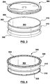
FIG. 3 illustrates a top view of a hermetic seal assembly having a lid detached from a collar; -
FIG. 4 illustrates a bottom view of a collar of a hermetic seal assembly; -
FIG. 5 illustrates a bag with a laminated polypropylene sheet or film; -
FIG. 6 illustrates a ribbon-woven structure of a bag; -
FIG. 7 illustrates a container bag; -
FIG. 8 illustrates a hermetic seal assembly integrated to a side of a bag having an opening; -
FIG. 9 illustrates a collar of a hermetic seal assembly affixed around an open end of a bag; -
FIG. 10 illustrates a hermetic seal assembly that seals an open end of a bag; -
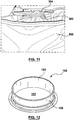
FIG. 11 illustrates a hermetic seal assembly that seals an opening of a bag; -
FIG. 12 illustrates a perspective view of a collar of a hermetic seal assembly; -
FIG. 13 illustrates a top view of a collar of a hermetic seal assembly; -
FIG. 14 illustrates a bottom view of a collar of a hermetic seal assembly; -
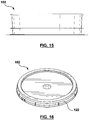
FIG. 15 illustrates a front side view of a collar of a hermetic seal assembly, wherein a back view, left view, and right view are mirror-images thereof; -
FIG. 16 illustrates a perspective view of a lid of a hermetic seal assembly; -
FIG. 17 illustrates a bottom view of a lid of a hermetic seal assembly; -
FIG. 18 illustrates a top view of a lid of a hermetic seal assembly; -
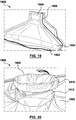
FIG. 19 illustrates a view of an outer layer and an inner layer of a bag having a neck and an opening; -
FIG. 20 illustrates a view of an opening on a bag having an outer layer and an inner layer; and -
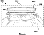
FIG. 21 illustrates a view of a hermetic seal assembly used with a bag having one or more layers with a compression member to facilitates connectivity. - Embodiments of the invention relate to methods and systems that relate to a hermetic seal assembly used with a bulk bag to provide a hermetic seal for the bulk bag that can be opened and closed while maintaining the hermetic seal for the bulk bag and materials stored therein. The hermetic seal assembly can include a lid and a collar, wherein the collar can be releasably affixed to a portion of the bulk bag or integrated into an opening of the bulk bag.
- "Welding" or "weld" as used herein including any other formatives of these words will refer to depositing of molten material through the operation of an electric arc including but not limited to submerged arc, GTAW, GMAW, MAG, MIG, TIG welding, any high energy heat source (e.g., a laser, an electron beam, among others), or any electric arc used with a welding system. Moreover, the welding operation can be on a workpiece that includes a coating such as, but not limited to, a galvanized coating.
- "Component" or "Controller" as used herein can be a portion of hardware, a portion of software, or a combination thereof that can include or utilize at least a processor and a portion of memory, wherein the memory includes an instruction to execute.
- "Bag" as used herein can be a bulk bag, a container bag, and/or an item that houses a material, wherein the material housed or stored can be a solid, liquid, gas, or a combination thereof. The bag can include an inner layer and an outer layer, wherein the inner layer provides a barrier to atmospheric conditions and the outer layer provides durability and rigidity. In an embodiment, the outer layer can be a ribbon-woven structure. The inner layer and/or the outer layer can be made of any suitable materials chosen with sound engineering judgment. In an example, the bag can include one or more chambers in which each chamber stores or houses a material. For example, a bag can include a first chamber that stores or houses a first material, a second chamber that stores or houses a second material, and a third chamber that houses or stores a third material. In such example, each chamber can include an appropriate material for the respective layer based at least in part upon the material contained therein. It is to be further appreciated that each layer of the bag can include a thickness, wherein the thickness can be based on at least one of the material stored within such chamber or the material of which the layer is fabricated. The bag can be a shape and a size, wherein the bag includes at least one of an open end or an opening. It is to be appreciated that the bag can include one or more open ends. In another example, it is to be appreciated that the bag can include one or more openings. The bag can be configured to define a volume and having a shape with at least one opening to access or dispense/fill.
- While the embodiments discussed herein have been related to the systems and methods discussed above, these embodiments are intended to be exemplary and are not intended to limit the applicability of these embodiments to only those discussions set forth herein. The control systems and methodologies discussed herein are equally applicable to, and can be utilized in, systems and methods related to arc welding, laser welding, brazing, soldering, plasma cutting, waterjet cutting, laser cutting, and any other systems or methods using similar control methodology, without departing from the spirit or scope of the above discussed inventions. The embodiments and discussions herein can be readily incorporated into any of these systems and methodologies by those of skill in the art. By way of example and not limitation, a power supply as used herein (e.g., welding power supply, among others) can be a power supply for a device that performs welding, arc welding, laser welding, brazing, soldering, plasma cutting, waterjet cutting, laser cutting, among others. Thus, one of sound engineering and judgment can choose power supplies other than a welding power supply without departing from the intended scope of coverage of the embodiments of the subject invention.
- Additionally, the hermetic seal assembly described herein can relate to any environment in which a bag is used and the contents of such bag need not be related to a welding environment or welding system.
- With reference to the drawings, like reference numerals designate identical or corresponding parts throughout the several views. However, the inclusion of like elements in different views does not mean a given embodiment necessarily includes such elements or that all embodiments of the invention include such elements. The examples and figures are illustrative only and not meant to limit the invention, which is measured by the scope and spirit of the claims.
-
FIGs. 1 through 4 and12 through 18 illustrate ahermetic seal assembly 100 that includes acollar 102 and alid 104. Thecollar 102 can include atop end 106 and abottom end 108 opposite thereto. Thecollar 102 can include a through passage 103 (shown inFIG. 12 ) between thetop end 106 and thebottom end 108. Thecollar 102 can be utilized with a hermetic seal assembly for a bag in which thecollar 102 is affixed to the opening of the bag or placed around an open end of a bag. Thelid 104 can be releaseably coupled to thecollar 102, wherein thelid 104 can include atop side 118, abottom side 120, a sidewall in between the top side and the bottom side, and anoverhang 122 on the perimeter of thelid 104. In an embodiment, thelid 104 can include a locking mechanism that can be removed on a first opening of thelid 104 from thecollar 102. - The
collar 102 can include aninternal wall 124 and anexternal wall 126. In an embodiment, thecollar 102 and thelid 104 can be circular in shape. It is to be appreciated that the shape of thecollar 102 and thelid 104 can be chosen with sound engineering judgment and the shape of thecollar 102 and/or thelid 104 is not limiting on the subject innovation. Thecollar 102 can include alip 110 on thetop end 106, wherein thelip 110 is configured to mate with agap portion 128 on a bottom side of thelid 104. Theexternal wall 126 of thecollar 102 can further include aweb 111 that is used to integrate or couple at least one of a portion of the bag or a layer of the bag. In particular, an opening of the bag can include a perimeter, wherein theweb 111 is heat welded such that a perimeter of theweb 111 matches to the perimeter of the opening of the bag. Theweb 111 can include afirst portion 114 for rigidity and asecond portion 116 that, upon heat welding, integrates with at least one of the bag or the one or more bag layers (e.g., inner layer, outer layer, additional layer, combination thereof). It is to be appreciated that thefirst portion 114 has a first thickness and thesecond portion 116 has a second thickness, wherein the first thickness is greater than the second thickness. - The
collar 102 can further include asupport rib 112 that is located on theexternal wall 126 of thecollar 102 and in between thelip 110 and theweb 111. Thesupport rib 112 can be used to provide support of the hermetic seal assembly and/or the bag during filling, refilling, emptying, accessing contents of the bag, cleaning, among others. Moreover, a portion of the bag can be integrated or coupled to thecollar 102 on theexternal wall 126 at a location between thesupport rib 112 and thebottom end 108 or theweb 111. - In an embodiment, the
collar 104 can be integrated to an opening of a bag (discussed in more detail below and shown in at leastFIG. 8 ). In particular, thecollar 102 can be integrated with or coupled to at least one of the bag or the one or more layers of the bag in which a perimeter of thebottom end 108 of thecollar 102 is integrated to a perimeter of an opening of the bag. It is to be appreciated that thecollar 102 can be coupled to a portion of the bag or a portion of the opening of the bag. In another embodiment, thecollar 102 can be placed around an open end of the bag in which the bag is folded outward over thecollar 102, wherein thelid 104 compresses and seals the folded portion of the bag between thelid 103 and thelip 110 of the collar 102 (discussed below and shown in at leastFIGs. 9-11 ). In such embodiment, the portion of the open end of the bag can be integrated or coupled to a portion of the collar. Continuing with such embodiment, a portion of the bag where the opening is located can be placed through the throughpassage 103. A portion of the bag that is through thecollar 102 can be turned inside out (e.g., folded) over thecollar 102 and thelid 104 can be releaseably affixed to thecollar 102 such that the bag is pinched in between thelid 104 and the collar while closing the opening. - As discussed above, the
hermetic seal assembly 100 can include thecollar 102 and thelid 104, wherein each can include respective shapes and dimensions such that thelid 104 can releaseably couple to thecollar 102. In an embodiment, thecollar 102 can include an inner diameter of approximately 10 inches to 14 inches. Moreover, the height (e.g., between thetop end 106 and the bottom end 108) of thecollar 102 can be approximately 1 inch to 5 inches. Theweb 111 can have a width from theexternal wall 126 outwardly of approximately 1 inch to 5 inches. Moreover, thefirst thickness 114 of theweb 111 can be approximately 1/8 inch and thesecond thickness 116 can be .015 of an inch. However, it is to be appreciated that the diameter, height, shape, and/or size of the collar or any components of the hermetic seal assembly (e.g., lid, web, etc.) can be chosen with sound engineering judgment without departing from the scope of the subject innovation. - In an embodiment, the
web 111 can be inserted between the inner layer of the bag and the outer layer of the bag, wherein the web is integrated to a portion of the inner layer or the outer layer. In another embodiment, the inner layer and the outer layer can be integrated together and integrated or coupled to a portion of thecollar 102 such that a bottom side of theweb 111 is integrated or coupled thereto. In another embodiment, the inner layer and the outer layer can be integrated together and integrated or coupled to a portion of thecollar 102 such that a top side of theweb 111 is integrated or coupled thereto. -
FIG. 2 illustrates thelid 104 affixed or releaseably coupled to thecollar 102. Thelid 104 can include atop side 118 and abottom side 120 and a sidewall there between, wherein thebottom side 120 includes agap 128 that is configured to receive with a portion of thelip 110 on thecollar 102. It is to be appreciated that thegap 128 can be positioned on thebottom side 120 of thelid 104, wherein thegap 128 and thelip 110 utilize a tongue-and-groove connectivity. Thelid 104 can be configured to be releaseably coupled to thecollar 102 and such connectivity can be selected with sound engineering judgment without departing from the scope of the subject innovation. By way of example and not limitation, thelid 104 can be coupled with thecollar 102 by at least one of a male-to-female coupling, a threading connection, a pressure-fit connection, a tongue-and-groove connection, among others. -
FIG. 3 illustrates a top perspective view of an embodiment of ahermetic seal assembly 300 that includes acollar 302 and alid 304 that are attachable to an open end of a bag by inserting the open end of the bag through thecollar 302, folding the ends around thecollar 302, and using thelid 304 to press the portion of the bag against the top end of thecollar 302.FIG. 4 illustrates a bottom perspective view of thehermetic seal assembly 300. Thecollar 302 can include atop end 306 and abottom end 308 opposite thereto. Thecollar 302 can include a throughpassage 303 between thetop end 306 and thebottom end 308. Thecollar 302 can be utilized with a hermetic seal assembly for a bag in which a portion of the bag is placed through the throughpassage 303 of thecollar 302. Thelid 304 can be releaseably coupled to thecollar 302. In an embodiment, thelid 304 can include a locking mechanism that can be removed on a first opening of thelid 304 from thecollar 302. - The
collar 302 can include aninternal wall 324 and anexternal wall 326. In an embodiment, thecollar 302 and thelid 304 can be circular in shape. It is to be appreciated that the shape of thecollar 302 and thelid 304 can be chosen with sound engineering judgment and the shape of thecollar 302 and/or thelid 304 is not limiting on the subject innovation. Thecollar 302 can include alip 310 on thetop end 306, wherein thelip 310 is configured to mate with a gap or rim portion on a bottom side of thelid 304. - The
collar 302 can further include asupport rib 312 that is located on theexternal wall 326 of thecollar 302 and in between thelip 310 and thebottom end 308 Thesupport rib 312 can be used to provide support of the hermetic seal assembly and/or the bag during filling, refilling, emptying, accessing contents of the bag, cleaning, among others. - It is to be appreciated that the
lid 104 can be used with thecollar 102 or thecollar 302. In another embodiment, it is to be appreciated that thelid 304 can be used with thecollar 302 or thecollar 102. In other words, the lid can be universal or specific to an embodiment of the collar of a hermetic seal assembly. -
FIG. 5 illustrates an embodiment of a ribbon-wovenbag 500. Thebag 500 can be a ribbon-woven polypropylene bag structure, all of the refuse at a typical jobsite can be contained safely within a bag formed with the ribbon weaving so that the bag can be a one-use bag which is provided folded up at the jobsite and then opened and filled. Once filled, thebag 500 is capable of being lifted by its top and transported to a refuse disposal location. Thebag 500 can have aside 502 comprised ofwoven ribbons 504 running longitudinally andribbons 506 running laterally.Bag 500 can include aclosed end 510 and anopen end 508. In an embodiment, theclosed end 510 can be folded upon itself as illustrated and stitched at the bottom of the bag via stitching 512 to complete thebag 500. Thebag 500 can include theopen end 508, theclosed end 510 opposite thereto, theside 502, a back side (opposite the front side 502), a left side, and a right side. Thebag 500 can house or store a volume. As discussed above, thebag 500 can include one or more layers. For instance, thebag 500 can include an inner layer that is hermetically sealed and an outer layer outside the inner layer, wherein the outer layer is ribbon-woven having the sidewalls (e.g., front, back, left, right) and theopen end 508 and theclosed end 510. This is further illustrated inFigs. 19-21 . - A shape of the
bag 500 can be selected with sound engineering judgement without departing from the scope of the subject innovation, wherein the shape is configured to store or house a volume of material. In an embodiment, the shape of thebag 500 can be cube-like, with a front side, back side opposite the front side, a left side, a right side opposite the left side, a top side, and a bottom side opposite the top side. In an example, thebag 500 can include at least one opening to which an inside of thebag 500 can be accessed. In another example, thebag 500 can include an open end, wherein at least one of the front side, back side, left side, right side, top side, or bottom side is open. - Turning to
FIG. 6 , a portion of theribbon weave 600 for thebag 500 is illustrated. In an embodiment, the width of the ribbons can be between two (2) and eight (8) millimeters but the width can be selected with sound engineering judgment based on at least the material to be housed/stored in the bag. For example, it is to be appreciated that the tighter the weave, meaning the less wide the ribbon, the greater will be the physical strength characteristics of the bag. The utilization of the wider ribbon can translate to less weaving is involved and therefor the bag may be lighter than the tighter weave. - Turning to
FIG. 9, 10 , and11 , utilizing thecollar 302 andlid 304 with thebag 500 is illustrated. Thecollar 302 andlid 304 can be used with thebag 500 in which theopen end 508 of thebag 500 is placed through thecollar 302, and in particular, theopen end 508 is inserted into the through passage 303 (shown inFIG. 3 ). The portion of theopen end 508 of thebag 500 is inserted through thetop end 306 and is fanned out around thelip 310 of thecollar 302. Thelid 304 can be placed onto thecollar 302 to pinch the perimeter of the opening of thebag 500 between thelid 304 and thelip 310 of thecollar 302. In particular, thelip 310 is in contact with a portion of anouter layer 501 of the bag 500 (folded over the collar 302) and thelid 304 is in contact with aninner layer 503 of the bag 500 (shown inFIGs. 10 and11 ). This connectivity allows thecollar 302 and thelid 304 to provide a hermetic seal for the opening of thebag 500, wherein thelid 304 is sealable and resealable. Thecollar 302 and thelid 304 can be utilized with a bag that has an opening (such as the opening 508) and is adaptable and/or usable with bags without any changes structural changes or modifications to the bag. - Turning to
FIG. 7 , abag 700 is illustrated in a perspective view.Bag 700 can be typically shipped or transported on apallet 702. Thebag 700 can include one ormore loops 704 adjacent anupper surface 706. For example, the one ormore loops 704 can facilitate moving thebag 700 to and from different locations. Thebag 700 can include sidewalls 708 (e.g., front, back, left, right). Thebag 700 can further include a top side and a bottom side opposite thereto, wherein the top side can include an opening. In other embodiment, thebag 700 can include an open end on the top side in which acollar 302 andlid 304 can be utilized to provide a hermetic seal. -
FIG. 8 illustrates thecollar 102 integrated into abag 700, wherein thelid 104 is shown attached to the collar providing a hermetic seal. In particular, thecollar 102 is integrated to a top side of thebag 700 but it is to be appreciated that thecollar 102 can be integrated into any side or location of thebag 700. For example, the hermetic seal assembly (e.g.,collar 102, lid 104) can be on a sidewall of thebag 700 or a bottom side of thebag 700. -
FIGs. 12 through 15 illustrate thecollar 102. In particular,FIG. 12 is a perspective view of thecollar 102.FIG. 13 illustrates a top view of thecollar 102 of a hermetic seal assembly.FIG. 14 illustrates a bottom view of thecollar 102 of a hermetic seal assembly.FIG. 15 illustrates a front side view of thecollar 102 of a hermetic seal assembly, wherein a back view, left view, and right view are mirror-images thereof. -
FIGs. 16 through 18 illustrate a lid that is used with the hermetic seal assembly in accordance with the subject innovation.FIG. 16 is a perspective view of a lid used with the hermetic seal assembly.FIG. 17 illustrates a bottom view of a lid of a hermetic seal assembly.FIG. 18 illustrates a top view of a lid of a hermetic seal assembly. - As discussed above, a portion of the collar 102 (shown in
Fig. 1 ) can be integrated or coupled to a portion of a bag. In another embodiment, a portion of the collar 302 (shown inFig. 3 ) can be integrated or coupled to a portion of a bag. It is to be appreciated that the integration or coupling can be selected with sound engineering judgment without departing from the scope of the subject innovation. By way of example and not limitation, the integrating of a portion of a collar to a portion of a bag can be, but is not limited to, hot plate welding, flat platen welding, impulse welding, hot bar welding, interweaving of a portion of the bag and a portion of the collar, inserting a portion of the collar in between one or more layers of the bag, melting a portion of the bag onto the collar, melting a portion of the collar onto the bag, a combination thereof. In another embodiment, a portion of the collar can be coupled to a portion of the bag, wherein such coupling can be, but is not limited to, glue, taped, adhered, bolted, riveted, or a combination thereof. - In still another embodiment, the
collar 302 can be releaseably coupled to an exterior layer or an outer layer of the bag after being inserted into thecollar 302 through theopening 303. The one or more layers of the bag can be integrated with or coupled to at least one of anexternal wall 326 of thecollar 302, aninterior wall 324 of thecollar 302, thelip 310, thebottom end 308, thesupport rib 312, or a combination thereof. - In an embodiment, an open end of the bag can include a compression member 1914 that facilitates connectivity between the bag and the
collar 302. For example, with an open end of the bag being inserted through thecollar 302 and being folded over thelip 310 of the collar, a compression member 1914 can be placed to maintain a force so a portion of the folded bag is coupled to a portion of thecollar 302. It is to be appreciated that the compression member 1914 can be integrated or woven into the open end of the bag or a separate component not woven or part of the bag. The compression member 1914 can apply a force that squeezes a portion of the bag to couple to a portion of thecollar 302. - Turning to
FIGs. 19-21 , the hermetic seal assembly system is illustrated.Fig. 19 illustrates a portion of abag 1900, wherein the bag has a cube-like shape (e.g., a bottom, a left side, a right side, a front side, a back side, and a top) with an opening on the top. InFig. 19 , the bag is illustrated having anouter layer 1902 and aninner layer 1904. By way of example and not limitation theinner layer 1902 can be a foil laminate and theouter layer 1904 can be a ribbon-woven polypropylene structure. It is to be appreciated that thebag 1900 can include one or more layers and theouter layer 1902 and theinner layer 1904 are not to be limited on the subject innovation. Moreover, theouter layer 1902 can be fabricated from a first material and theinner layer 1904 can be fabricated from a second material, wherein the first material can be chosen with sound engineering judgment to provide the bag with structural strength, integrity, and durability and the second material can be chosen with sound engineering judgment to prevent air from entering theinner layer 1904 or contaminating the material stored or housed within theinner layer 1904. For instance, theouter layer 1902 can be a ribbon weave with one or more materials in ribbon or fiber form. In another instance, theinner layer 1904 can be a plastic or other airtight material. - The
inner layer 1904 can be created to be an airtight and/or hermetic seal for thebag 1900 which does not allow exposure of contents of theinner layer 1904. Theinner layer 1904 can be created from one or more sheets of material and coupled together to create a shape having a volume that stores a material. By way of example and not limitation, the shape of theinner layer 1904 of the bag can be a cube such that the cube is formed with 6 (six) sheets of material that are coupled together at seams to form the cube-like shape. As discussed, theinner layer 1904 can include an opening that is hermetically sealed but can be opened or broken when contents of the bag are ready for use. It is to be appreciated that theouter layer 1902 can include an exterior and an interior, wherein the interior is in contact with exterior of theinner layer 1904 and the exterior is exposed to elements outside the bag. Further, it is to be appreciated that theinner layer 1904 can include an exterior and an interior, wherein the interior is in contact with the materials stored therein and the exterior is in contact with the interior of theouter layer 1902. If an additional layer is included with thebag 1900, the additional layer can be positioned in between theouter layer 1902 and theinner layer 1904. -
FIG. 19 illustrates thebag 1900 with theouter layer 1902 removed on the top side of the bag to expose and illustrate theinner layer 1904 and anopening 1908. In an embodiment, theinner layer 1904 can be fabricated with seams to form the shape of thebag 1900 such that theopening 1908 is positioned on the top side of thebag 1900 and in the center of the top side. Theopening 1908 can be formed from theinner layer 1904 which creates aneck 1906. It is to be appreciated that theouter layer 1902 surrounds theinner layer 1904 and would have an opening that corresponds to theopening 1908 yet theouter layer 1902 is partially shown in order to illustrate theinner layer 1902. -
FIG. 20 illustrates a view of thebag 1900 and the neck of theouter layer 1902 and theinner layer 1904 folded.FIG. 20 illustrates thebag 1900 having theouter layer 1902 and theinner layer 1904, both are folded creating anouter layer fold 1912 and aninner layer fold 1910. Theopening 1908 can be further exposed while reducing a size of theneck 1906 by rolling or folding theinner layer 1904 and theouter layer 1902. In an embodiment, theinner layer 1904 can be rolled or folded separately from the outer layer 1902 (as shown inFIG. 20 ). In another embodiment, theouter layer 1902 and theinner layer 1904 can be folded or rolled together (as shown inFIG. 21 ). In either embodiment, thecollar 302 can be positioned over theopening 1908 to allow the rolled or folded portion of the layer(s) to be positioned on theexternal wall 326 of thecollar 302, wherein thelip 310 of thecollar 302 is in contact with at least one of an exterior of theinner layer 1904 or an exterior of theouter layer 1902. For example, if theouter layer 1902 and theinner layer 1904 are folded or rolled together over thelip 310 of thecollar 302, thelip 310 is in contact with an exterior of theouter layer 1902. In another example, if theinner layer 1904 is folded or rolled separately over thelip 310 of thecollar 302, thelip 310 will be in contact with an exterior of theinner layer 1904. The number of folds or rolls can be selected with sound engineering judgment so as to reduce theneck 1908 so thecollar 302 can fit over the opening and allow thelid 304 to couple to the collar while such coupling pinches the layer(s) of the bag together. It is to be appreciated that excess material of the bag from folding or rolling can be removed or cut off from thebag 1900. -
FIG. 21 illustrates thecollar 302 coupled to the folded layers (e.g., theouter layer 1902, the inner layer 1904), wherein the coupling is such that thecollar 302 is placed over theopening 1908 and the folded layers are placed on theexterior surface 324 of thecollar 302. Thecollar 302 can be affixed or coupled to thebag 1900 at the position where the layers are folded and at theopening 1908. The coupling can be such that theouter layer 1902 and theinner layer 1904 are folded over thelip 310, theouter layer 1902 is in contact with thelip 310, and theinner layer 1904 is exposed to outside thebag 1900. Thelid 304 can be affixed to thelip 310 of the collar to pinch the layers of the bag between thelid 304 and thelip 310 of thecollar 302. Thecompression member 1912 can be further positioned around thecollar 302 and the folded layers to press the folded layers against theexternal wall 326. It is to be appreciated that thecompression member 1912 can be a rubber material, a polymer, a synthetic material, a natural material, a clamp, a bungie cord, a rope, a string, a ratchet straps, tie downs, a plastic member that is shrink wrapped, an elastic band, among others. - In an embodiment, the collar is a first shape having a first size and the opening of the bag is the first shape having a second size, wherein the first size is greater than the second size. In an embodiment, the web extending outwardly from the bottom end. In an embodiment, the web includes a first thickness and a second thickness, wherein the first thickness is greater than the second thickness and positioned proximate to the bottom end in comparison to the second thickness. In an embodiment, a portion of the web is integrated between one or more layers of the bag. In an embodiment, a portion of the web is integrated to the inner layer of the bag. In an embodiment, a portion of the web is coupled to the outer layer, and the outer layer is coupled to the inner layer. In an embodiment, a portion of the web is coupled to the inner layer of the bag. In an embodiment, the seal assembly further comprises a heat weld that secures a portion of the collar to a portion of the bag. In an embodiment, the seal assembly further comprises a support rib on an external wall of the collar in between the lip and the web.
- The aforementioned systems, components, (e.g., hermetic
seal assembly system 100,hermetic seal assembly 300,collar 102,lid 104,collar 302,lid 304,bag 500,bag 700,bag 1900,compression member 1912, among others), and the like have been described with respect to interaction between several components and/or elements. It should be appreciated that such devices and elements can include those elements or sub-elements specified therein, some of the specified elements or sub-elements, and/or additional elements. Further yet, one or more elements and/or sub-elements may be combined into a single component to provide aggregate functionality. The elements may also interact with one or more other elements not specifically described herein. - While the embodiments discussed herein have been related to the systems and methods discussed above, these embodiments are intended to be exemplary and are not intended to limit the applicability of these embodiments to only those discussions set forth herein. The control systems and methodologies discussed herein are equally applicable to, and can be utilized in, systems and methods related to arc welding, laser welding, brazing, soldering, plasma cutting, waterjet cutting, laser cutting, and any other systems or methods using similar control methodology, without departing from the spirit or scope of the above discussed inventions. The embodiments and discussions herein can be readily incorporated into any of these systems and methodologies by those of skill in the art. By way of example and not limitation, a power supply as used herein (e.g., welding power supply, among others) can be a power supply for a device that performs welding, arc welding, laser welding, brazing, soldering, plasma cutting, waterjet cutting, laser cutting, among others. Thus, one of sound engineering and judgment can choose power supplies other than a welding power supply departing from the intended scope of coverage of the embodiments of the subject invention.
- The above examples are merely illustrative of several possible embodiments of various aspects of the present invention, wherein equivalent alterations and/or modifications will occur to others skilled in the art upon reading and understanding this specification and the annexed drawings. In particular regard to the various functions performed by the above described components (assemblies, devices, systems, circuits, and the like), the terms (including a reference to a "means") used to describe such components are intended to correspond, unless otherwise indicated, to any component, such as hardware, software, or combinations thereof, which performs the specified function of the described component (e.g., that is functionally equivalent), even though not structurally equivalent to the disclosed structure which performs the function in the illustrated implementations of the invention. In addition although a particular feature of the invention may have been disclosed with respect to only one of several implementations, such feature may be combined with one or more other features of the other implementations as may be desired and advantageous for any given or particular application. Also, to the extent that the terms "including", "includes", "having", "has", "with", or variants thereof are used in the detailed description and/or in the claims, such terms are intended to be inclusive in a manner similar to the term "comprising."
- This written description uses examples to disclose the invention, including the best mode, and also to enable one of ordinary skill in the art to practice the invention, including making and using any devices or systems and performing any incorporated methods. The patentable scope of the invention is defined by the claims, and may include other examples that occur to those skilled in the art. Such other examples are intended to be within the scope of the claims if they have structural elements that are not different from the literal language of the claims, or if they include equivalent structural elements with insubstantial differences from the literal language of the claims.
- In the specification and claims, reference will be made to a number of terms that have the following meanings. The singular forms "a", "an" and "the" include plural referents unless the context clearly dictates otherwise. Approximating language, as used herein throughout the specification and claims, may be applied to modify a quantitative representation that could permissibly vary without resulting in a change in the basic function to which it is related. Accordingly, a value modified by a term such as "about" is not to be limited to the precise value specified. In some instances, the approximating language may correspond to the precision of an instrument for measuring the value. Moreover, unless specifically stated otherwise, a use of the terms "first," "second," etc., do not denote an order or importance, but rather the terms "first," "second," etc., are used to distinguish one element from another.
- As used herein, the terms "may" and "may be" indicate a possibility of an occurrence within a set of circumstances; a possession of a specified property, characteristic or function; and/or qualify another verb by expressing one or more of an ability, capability, or possibility associated with the qualified verb. Accordingly, usage of "may" and "may be" indicates that a modified term is apparently appropriate, capable, or suitable for an indicated capacity, function, or usage, while taking into account that in some circumstances the modified term may sometimes not be appropriate, capable, or suitable. For example, in some circumstances an event or capacity can be expected, while in other circumstances the event or capacity cannot occur - this distinction is captured by the terms "may" and "may be."
- The best mode for carrying out the invention has been described for purposes of illustrating the best mode known to the applicant at the time and enable one of ordinary skill in the art to practice the invention, including making and using devices or systems and performing incorporated methods. The examples are illustrative only and not meant to limit the invention, as measured by the scope and merit of the claims. The invention has been described with reference to preferred and alternate embodiments. Obviously, modifications and alterations will occur to others upon the reading and understanding of the specification. It is intended to include all such modifications and alterations insofar as they come within the scope of the appended claims or the equivalents thereof. The patentable scope of the invention is defined by the claims, and may include other examples that occur to one of ordinary skill in the art. Such other examples are intended to be within the scope of the claims if they have structural elements that do not differentiate from the literal language of the claims, or if they include equivalent structural elements with insubstantial differences from the literal language of the claims.
- The invention described herein generally pertains to a system and method related to a hermetic seal assembly used with a bag to provide a hermetic seal for the bag that can be opened and closed while maintaining the hermetic seal for the bag and materials stored therein. The hermetic seal assembly can include a lid and a collar, wherein the collar can be releasably affixed to the bag or integrated into an opening of the bag.
REFERENCE NUMERALS 100 seal assembly 312 support rib 102 collar 324 internal wall 103 passage 326 external wall 104 lid 500 bag 106 top end 502 side 108 bottom end 504 woven ribbon 110 lip 506 ribbon 111 web 508 open end 112 support rib 510 closed end 114 first portion 512 stitching 116 second portion 600 ribbon weave 118 top side 700 bag 120 bottom side 704 loop 122 overhang 706 upper surface 124 internal wall 708 sidewalls 126 external wall 1900 bag 128 gap 1902 outer layer 300 seal assemby 1904 inner layer 302 collar 1906 neck 304 lid 1908 opening 306 top end 1910 inner layer fold 308 bottom end 1912 outer layer fold 310 lip 1914 compression member
Claims (15)
- A seal assembly system for a bulk bag, comprising:a bag (700) that stores a material, the bag includes an opening;the bag (700) includes an inner layer (1904) and an outer layer (1902), whereinthe inner layer (1904) is a foil laminate and the outer layer (1902) is a ribbon-woven structure (600) made of polypropylene;a collar (302) having a top end (306) and a bottom end (308) opposite thereto, an internal wall (324) that defines a through passage that extends between the top end (306) and the bottom end (308);characterized bythe collar (302) having:a lip (310) on the top end;a web on the bottom end (308); andthe web of the collar (302) is integrated to the inner layer (1904) and the outer layer (1902) at the opening; anda lid (304) that is configured to releaseably attach to the lip (310) of the collar (302) to provide a hermetic seal at the opening.
- The seal assembly system of claim 1, the collar (302) is a first shape having a first size and the opening of the bag (700) is the first shape having a second size, wherein the first size is greater than the second size.
- The seal assembly system of claim 1 or 2, the web extending outwardly from the bottom end (308).
- The seal assembly system of one of the claims 1 to 3, the web includes a first thickness and a second thickness, wherein the first thickness is greater than the second thickness and positioned proximate to the bottom end (308) in comparison to the second thickness.
- The seal assembly system of one of the claims 1 to 4, a portion of the web is integrated between one or more layers (1902, 1904) of the bag (700).
- The seal assembly system of one of the claims 1 to 5, a portion of the web is integrated and/or coupled to the inner layer (1904) of the bag (700).
- The seal assembly system of one of the claims 1 to 6, a portion of the web is coupled to the outer layer (1902), and the outer layer (1902) is coupled to the inner layer (1904).
- The seal assembly system of one of the claims 1 to 7, further comprising a heat weld that secures a portion of the collar (302) to a portion of the bag (700).
- The seal assembly system of one of the claims 1 to 8, further comprising a support rib (312) on an external wall (326) of the collar (302) in between the lip (310) and the web.
- A bag (700) having a cube-like shape that is configured to hold a volume of a material, the bag (700) having a front side, a back side opposite to the front side, a left side, a right side opposite the left side, a top side, and a bottom side opposite the top side;
the bag comprising:an inner layer (1704) that is configured to provide an airtight enclosure for the material, wherein the airtight enclosure can be accessed via the opening;an outer layer (1702) that is positioned around the inner layer (1702), wherein the outer layer (1702) provides structural support and integrity with a ribbon weave; andan opening on the top side of the bag (700), wherein the opening is formed by at least one of the inner layer (1704) or the outer layer (1702);characterized in that
the opening includes a neck (1906) formed by at least one of the inner layer (1904) or the outer layer (1902);a collar (302) having a top end (306) and a bottom end (308) opposite thereto, an internal wall (324) that defines a through passage that extends between the top end (306) and the bottom end (308), an external wall (326) opposite the internal wall (324), and the collar (302) having a thickness and a diameter for the through passage;the collar (302) positioned over the neck (1906) and with at least one of the inner layer (1904) or the outer layer (1902) folded over a lip (310) of the collar (302), wherein at least one of the inner layer (1904) or the outer layer (1902) are folded onto the external wall (326) of the collar (302); anda lid (304) that is releaseably coupled to the collar (302), the lid (304) when attached to the collar (302) applies a force to press the lid (304), the outer layer (1904), the inner layer (1902), and the lip (310) of the collar (302) together. - The bag of claim 10, wherein the outer layer (1902) is a polypropylene and/or wherein the inner layer (1904) is a foil laminate.
- The bag of claim 10 or 11, further comprising a compression member that compresses one of the inner layer or the outer layer to the external wall of the collar to maintain connectivity upon detachment of the lid from the collar, wherein the compression member preferably is a polymer.
- The bag of one claims 10 to 12, wherein the lip (110) of the collar (302) is in contact with an exterior of the outer layer (1902) and a bottom portion of the lid (304) is in contact with an interior of the inner layer (1904) when the lid (304) is coupled to the lip (110) of the collar (302); or wherein the lip (110) of the collar (302) is in contact with an exterior of the inner layer (1904) and a bottom portion of the lid (304) is in contact with an interior of the inner layer (1904) when the lid is coupled to the lip (110) of the collar (302).
- The bag of one of the claims 10 to 13, further comprising a portion of the neck of the bag (700) is integrated to a portion of the collar (302); and/or wherein the collar is a first shape having a first size and the opening of the bag is the first shape having a second size, wherein the first size is greater than the second size.
- A seal assembly system for a bulk bag, comprising:a bag that stores a material having a first end and a second end opposite thereto, the bag includes an opening at the first end;the bag includes an inner layer and an outer layer, wherein the inner layer is a foil laminate and the outer layer is a ribbon-woven structure made of polypropylene;a collar having a top end and a bottom end opposite thereto, an internal wall that defines a through passage that extends between the top end and the bottom end;the collar further includes an external wall;
the collar having:a lip on the top end;a web that is perpendicular and outward from the external wall; anda support rib in between the lip and the web;the collar is affixed around a portion of the bag such that the outer layer is in contact with the internal wall and the external wall;a compression member that is configured to be positioned around the collar to compress the outer layer and the inner layer toward the external wall of the collar; anda lid that is configured to releaseably attach to the lip of the collar to provide a hermetic seal at the opening, wherein the lip is in contact with the outer layer, the lid is in contact with the inner layer, and the lid couples to the lip with the outer layer and the inner layer in between.
Priority Applications (1)
| Application Number | Priority Date | Filing Date | Title |
|---|---|---|---|
| PL18000029T PL3348496T3 (en) | 2017-01-17 | 2018-01-16 | Seal assembly system |
Applications Claiming Priority (2)
| Application Number | Priority Date | Filing Date | Title |
|---|---|---|---|
| US201762447129P | 2017-01-17 | 2017-01-17 | |
| US15/785,551 US11167917B2 (en) | 2017-01-17 | 2017-10-17 | Hermetic seal for foil-lined FIBC (bulk bag) |
Publications (3)
| Publication Number | Publication Date |
|---|---|
| EP3348496A2 true EP3348496A2 (en) | 2018-07-18 |
| EP3348496A3 EP3348496A3 (en) | 2018-10-03 |
| EP3348496B1 EP3348496B1 (en) | 2019-11-27 |
Family
ID=61005683
Family Applications (1)
| Application Number | Title | Priority Date | Filing Date |
|---|---|---|---|
| EP18000029.1A Active EP3348496B1 (en) | 2017-01-17 | 2018-01-16 | Seal assembly system |
Country Status (9)
| Country | Link |
|---|---|
| US (1) | US11167917B2 (en) |
| EP (1) | EP3348496B1 (en) |
| JP (1) | JP6673946B2 (en) |
| CN (1) | CN108328091B (en) |
| BR (1) | BR102018000803B1 (en) |
| CA (1) | CA2991884C (en) |
| MX (1) | MX383278B (en) |
| PL (1) | PL3348496T3 (en) |
| RU (1) | RU2018101295A (en) |
Cited By (3)
| Publication number | Priority date | Publication date | Assignee | Title |
|---|---|---|---|---|
| CN111532570A (en) * | 2019-02-06 | 2020-08-14 | 林肯环球股份有限公司 | Hermetic seal for foil lined FIBC (bulk bag) |
| US10968036B2 (en) | 2017-01-17 | 2021-04-06 | Lincoln Global, Inc. | Hermetic seal for foil-lined FIBC (bulk bag) |
| US11167917B2 (en) | 2017-01-17 | 2021-11-09 | Lincoln Global, Inc. | Hermetic seal for foil-lined FIBC (bulk bag) |
Families Citing this family (1)
| Publication number | Priority date | Publication date | Assignee | Title |
|---|---|---|---|---|
| US20240180741A1 (en) * | 2022-12-05 | 2024-06-06 | Brian Zimmerman | Ostomy bag and method of using same |
Family Cites Families (36)
| Publication number | Priority date | Publication date | Assignee | Title |
|---|---|---|---|---|
| US2695741A (en) * | 1953-06-16 | 1954-11-30 | Stephen L Haley | Air evacuator for plastic bags |
| US3445055A (en) * | 1966-04-28 | 1969-05-20 | Parker Pace Corp | Reinforced laminated plastic materials |
| FR2002101A1 (en) | 1968-02-17 | 1969-10-03 | Pirelli | Extending conical base for flexible container - for cohesive particulate materials, for complete discharge through limited bore outlet |
| US4018253A (en) | 1975-10-09 | 1977-04-19 | Seth Ian Kaufman | Home vacuum apparatus for freezer bags |
| US4441622A (en) | 1980-04-18 | 1984-04-10 | Holdt J W Von | Threaded port and plug having access apertures |
| ZA819032B (en) * | 1981-01-07 | 1982-11-24 | Wrightcel Ltd | Container |
| EP0168974A3 (en) * | 1984-06-20 | 1987-02-04 | Bowater Packaging Limited | Lining for a flexible bulk container |
| US4833008A (en) * | 1985-10-04 | 1989-05-23 | B.A.G. Corporation | Metalized fabric |
| JPS62191698U (en) * | 1986-05-23 | 1987-12-05 | ||
| DE3938414C2 (en) * | 1989-08-19 | 1994-04-14 | Eurea Verpackung | Bulk goods container made of a woven carrier bag and carrier devices attached to it |
| US5743425A (en) * | 1995-01-26 | 1998-04-28 | Ellis; John N. | Permanently attachable bucket lid with airtight seal |
| US5851072A (en) * | 1996-11-26 | 1998-12-22 | Custom Packaging Systems, Inc. | Spout construction for bulk box liquid liner |
| US5882119A (en) * | 1997-02-24 | 1999-03-16 | Fadal, Ii; Robert E. | Portable liquid containers |
| DE29818049U1 (en) * | 1998-11-13 | 1999-05-12 | Eurea Verpackungsgesellschaft mbH & Co KG, 48432 Rheine | Flexible transport container |
| US6554810B1 (en) | 2000-07-12 | 2003-04-29 | Peter J. Wilk | Collapsible emesis container |
| US6692260B2 (en) | 2001-01-26 | 2004-02-17 | B G Products, Inc. | Business method and device for marketing automobile fluid replacement services |
| US20030016885A1 (en) | 2001-07-23 | 2003-01-23 | Cornelius Chow | Closure device and method of manufacture |
| US7125168B2 (en) * | 2002-12-18 | 2006-10-24 | Scholle Corporation | Large container having an outer bag and inner linear method of manufacturing same |
| CA2443480A1 (en) * | 2003-09-30 | 2005-03-30 | Syn-Tex Convertors Ltd. | A form for containing settable filler material during setting |
| GB0411660D0 (en) | 2004-05-25 | 2004-06-30 | Crackerbag S Ltd | Apparatus and method for transporting material |
| US7798711B2 (en) * | 2004-07-27 | 2010-09-21 | Cdf Corporation | Flexible liner for FIBC or bag-in-box container systems |
| US20060096985A1 (en) | 2004-11-09 | 2006-05-11 | Stolzman Michael D | Venting lid with safety seal |
| DE602005012776D1 (en) | 2004-11-18 | 2009-04-02 | Pathtainer Systems Internat Pt | Two-piece closure for a container |
| US8075189B2 (en) * | 2006-06-21 | 2011-12-13 | Bosch Pouch Systems Ag | Method for attaching a spout to a flexible film pouch |
| US20090230258A1 (en) | 2008-03-11 | 2009-09-17 | Mcfadden Jeff Noel | Portable tree or pole/post mounted recreational trash bag holder with lid |
| US20100096398A1 (en) * | 2008-10-16 | 2010-04-22 | Wilton Industries, Inc. | Pour and seal assembly and method of using the same |
| FR2942777B1 (en) * | 2009-03-06 | 2016-02-05 | Sartorius Stedim Biotech Sa | SELF-TIGHTENING SKIRT MOUNTING FOR THE FITTING OF, OR CONNECTION TO, AN ANNULAR, QUICK-SETTING AND REMOVAL COLLAR, INTENDED FOR BIOPHARMACEUTICALS |
| EP2421764B2 (en) | 2009-04-24 | 2022-01-05 | N.V. Nutricia | Container assembly having stacking provisions |
| US9061815B2 (en) * | 2010-09-22 | 2015-06-23 | Signode Industrial Group Llc | Container assembly and methods for making and using same |
| EP2644527B1 (en) * | 2010-11-22 | 2016-08-17 | Hosokawa Yoko Co., Ltd. | Bag with attached mouth member and connection structure of said bag |
| WO2012177645A2 (en) * | 2011-06-20 | 2012-12-27 | Graco Minnesota Inc. | Pour spout adapter assembly for pumping system |
| US9592944B2 (en) | 2011-08-29 | 2017-03-14 | Liqui-Box Corporation | Aseptic duckbill flip-cap fitment for a collapsible container |
| AU2013277125A1 (en) * | 2012-06-22 | 2015-01-22 | Danny Ness | Bulk bag apparatus |
| JP6199663B2 (en) | 2013-08-27 | 2017-09-20 | 日本マタイ株式会社 | Flexible container |
| CN106219037A (en) * | 2016-08-31 | 2016-12-14 | 徐晟伟 | A kind of sealer of plastic packaging bag |
| US11167917B2 (en) | 2017-01-17 | 2021-11-09 | Lincoln Global, Inc. | Hermetic seal for foil-lined FIBC (bulk bag) |
-
2017
- 2017-10-17 US US15/785,551 patent/US11167917B2/en active Active
-
2018
- 2018-01-12 CA CA2991884A patent/CA2991884C/en active Active
- 2018-01-15 BR BR102018000803-0A patent/BR102018000803B1/en active IP Right Grant
- 2018-01-15 MX MX2018000638A patent/MX383278B/en unknown
- 2018-01-15 RU RU2018101295A patent/RU2018101295A/en not_active Application Discontinuation
- 2018-01-16 CN CN201810037932.1A patent/CN108328091B/en active Active
- 2018-01-16 EP EP18000029.1A patent/EP3348496B1/en active Active
- 2018-01-16 PL PL18000029T patent/PL3348496T3/en unknown
- 2018-01-16 JP JP2018004610A patent/JP6673946B2/en active Active
Non-Patent Citations (1)
| Title |
|---|
| None |
Cited By (5)
| Publication number | Priority date | Publication date | Assignee | Title |
|---|---|---|---|---|
| US10968036B2 (en) | 2017-01-17 | 2021-04-06 | Lincoln Global, Inc. | Hermetic seal for foil-lined FIBC (bulk bag) |
| US11167917B2 (en) | 2017-01-17 | 2021-11-09 | Lincoln Global, Inc. | Hermetic seal for foil-lined FIBC (bulk bag) |
| CN111532570A (en) * | 2019-02-06 | 2020-08-14 | 林肯环球股份有限公司 | Hermetic seal for foil lined FIBC (bulk bag) |
| EP3693294A3 (en) * | 2019-02-06 | 2020-09-23 | Lincoln Global, Inc. | Hermetic seal for foil-lined fibc , bag |
| CN111532570B (en) * | 2019-02-06 | 2023-08-11 | 林肯环球股份有限公司 | Hermetic seal for foil lined bulk bags |
Also Published As
| Publication number | Publication date |
|---|---|
| EP3348496B1 (en) | 2019-11-27 |
| PL3348496T3 (en) | 2020-06-01 |
| US11167917B2 (en) | 2021-11-09 |
| MX383278B (en) | 2025-03-13 |
| EP3348496A3 (en) | 2018-10-03 |
| JP6673946B2 (en) | 2020-04-01 |
| RU2018101295A3 (en) | 2020-12-28 |
| MX2018000638A (en) | 2018-11-09 |
| RU2018101295A (en) | 2019-07-17 |
| BR102018000803B1 (en) | 2023-01-10 |
| US20180201438A1 (en) | 2018-07-19 |
| JP2018115032A (en) | 2018-07-26 |
| CN108328091A (en) | 2018-07-27 |
| CA2991884C (en) | 2025-12-09 |
| BR102018000803A2 (en) | 2018-10-30 |
| CA2991884A1 (en) | 2018-07-17 |
| CN108328091B (en) | 2019-11-12 |
Similar Documents
| Publication | Publication Date | Title |
|---|---|---|
| CA2991884C (en) | Hermetic seal for foil-lined bulk bag | |
| US5762421A (en) | Reusable bulk bag with liner | |
| US10968036B2 (en) | Hermetic seal for foil-lined FIBC (bulk bag) | |
| KR100310473B1 (en) | Grain insect storage method and grain storage container | |
| CN103282289B (en) | Comprise silk housing apparatus and the structure of container and bag | |
| US4830191A (en) | Intermediate bulk containers | |
| KR102492023B1 (en) | flexible intermediate bulk container and manufacturing method of thereof | |
| JP3245031B2 (en) | Bag body and bag-in-box for bag-in-box | |
| JPH0680149A (en) | Flexible bag-form container | |
| ES2256737T3 (en) | PACKING FOR FILTER MATERIAL (FILTER-TOW) HIGHLY COMPRESSED AND PROCEDURE FOR PRODUCTION. | |
| EP3693294A2 (en) | Hermetic seal for foil-lined fibc , bag | |
| US20120099809A1 (en) | Protective device for a draining valve fitted on bags intended for the transport and handling of liquid or quasi-liquid substances | |
| KR102431254B1 (en) | plastic liner with inner lining | |
| EP1940701A1 (en) | Container for a fluid | |
| WO2023196423A1 (en) | Outer cover for a flexible tank and optimized flexible tank for a 40 foot shipping container without a bulkhead | |
| US20160355331A1 (en) | Flexible Large Container With A Seam-Free Useful Space | |
| EP1568622A1 (en) | Transport tank and method for transporting cargo | |
| AU2013201046A1 (en) | Gusseted Bag | |
| US7490990B2 (en) | Inner bag for transport tank | |
| JP3417668B2 (en) | Transportation device and transportation method for fine powder | |
| CN212891932U (en) | Lining for container | |
| WO2019232602A1 (en) | Constructive arrangement in paper bag | |
| JPH11268762A (en) | Bag in box | |
| JP2018111532A (en) | Foldable container container | |
| JP2008296933A (en) | Three-layer paper bag |
Legal Events
| Date | Code | Title | Description |
|---|---|---|---|
| PUAI | Public reference made under article 153(3) epc to a published international application that has entered the european phase |
Free format text: ORIGINAL CODE: 0009012 |
|
| STAA | Information on the status of an ep patent application or granted ep patent |
Free format text: STATUS: THE APPLICATION HAS BEEN PUBLISHED |
|
| AK | Designated contracting states |
Kind code of ref document: A2 Designated state(s): AL AT BE BG CH CY CZ DE DK EE ES FI FR GB GR HR HU IE IS IT LI LT LU LV MC MK MT NL NO PL PT RO RS SE SI SK SM TR |
|
| AX | Request for extension of the european patent |
Extension state: BA ME |
|
| PUAL | Search report despatched |
Free format text: ORIGINAL CODE: 0009013 |
|
| AK | Designated contracting states |
Kind code of ref document: A3 Designated state(s): AL AT BE BG CH CY CZ DE DK EE ES FI FR GB GR HR HU IE IS IT LI LT LU LV MC MK MT NL NO PL PT RO RS SE SI SK SM TR |
|
| AX | Request for extension of the european patent |
Extension state: BA ME |
|
| RIC1 | Information provided on ipc code assigned before grant |
Ipc: B65D 88/16 20060101AFI20180829BHEP |
|
| STAA | Information on the status of an ep patent application or granted ep patent |
Free format text: STATUS: REQUEST FOR EXAMINATION WAS MADE |
|
| 17P | Request for examination filed |
Effective date: 20190402 |
|
| RBV | Designated contracting states (corrected) |
Designated state(s): AL AT BE BG CH CY CZ DE DK EE ES FI FR GB GR HR HU IE IS IT LI LT LU LV MC MK MT NL NO PL PT RO RS SE SI SK SM TR |
|
| GRAP | Despatch of communication of intention to grant a patent |
Free format text: ORIGINAL CODE: EPIDOSNIGR1 |
|
| STAA | Information on the status of an ep patent application or granted ep patent |
Free format text: STATUS: GRANT OF PATENT IS INTENDED |
|
| INTG | Intention to grant announced |
Effective date: 20190705 |
|
| GRAS | Grant fee paid |
Free format text: ORIGINAL CODE: EPIDOSNIGR3 |
|
| GRAA | (expected) grant |
Free format text: ORIGINAL CODE: 0009210 |
|
| STAA | Information on the status of an ep patent application or granted ep patent |
Free format text: STATUS: THE PATENT HAS BEEN GRANTED |
|
| AK | Designated contracting states |
Kind code of ref document: B1 Designated state(s): AL AT BE BG CH CY CZ DE DK EE ES FI FR GB GR HR HU IE IS IT LI LT LU LV MC MK MT NL NO PL PT RO RS SE SI SK SM TR |
|
| REG | Reference to a national code |
Ref country code: GB Ref legal event code: FG4D |
|
| REG | Reference to a national code |
Ref country code: CH Ref legal event code: EP |
|
| REG | Reference to a national code |
Ref country code: AT Ref legal event code: REF Ref document number: 1206444 Country of ref document: AT Kind code of ref document: T Effective date: 20191215 |
|
| REG | Reference to a national code |
Ref country code: DE Ref legal event code: R096 Ref document number: 602018001300 Country of ref document: DE |
|
| REG | Reference to a national code |
Ref country code: IE Ref legal event code: FG4D |
|
| REG | Reference to a national code |
Ref country code: SE Ref legal event code: TRGR |
|
| REG | Reference to a national code |
Ref country code: NL Ref legal event code: MP Effective date: 20191127 |
|
| REG | Reference to a national code |
Ref country code: LT Ref legal event code: MG4D |
|
| PG25 | Lapsed in a contracting state [announced via postgrant information from national office to epo] |
Ref country code: NL Free format text: LAPSE BECAUSE OF FAILURE TO SUBMIT A TRANSLATION OF THE DESCRIPTION OR TO PAY THE FEE WITHIN THE PRESCRIBED TIME-LIMIT Effective date: 20191127 Ref country code: GR Free format text: LAPSE BECAUSE OF FAILURE TO SUBMIT A TRANSLATION OF THE DESCRIPTION OR TO PAY THE FEE WITHIN THE PRESCRIBED TIME-LIMIT Effective date: 20200228 Ref country code: LT Free format text: LAPSE BECAUSE OF FAILURE TO SUBMIT A TRANSLATION OF THE DESCRIPTION OR TO PAY THE FEE WITHIN THE PRESCRIBED TIME-LIMIT Effective date: 20191127 Ref country code: FI Free format text: LAPSE BECAUSE OF FAILURE TO SUBMIT A TRANSLATION OF THE DESCRIPTION OR TO PAY THE FEE WITHIN THE PRESCRIBED TIME-LIMIT Effective date: 20191127 Ref country code: BG Free format text: LAPSE BECAUSE OF FAILURE TO SUBMIT A TRANSLATION OF THE DESCRIPTION OR TO PAY THE FEE WITHIN THE PRESCRIBED TIME-LIMIT Effective date: 20200227 Ref country code: LV Free format text: LAPSE BECAUSE OF FAILURE TO SUBMIT A TRANSLATION OF THE DESCRIPTION OR TO PAY THE FEE WITHIN THE PRESCRIBED TIME-LIMIT Effective date: 20191127 Ref country code: NO Free format text: LAPSE BECAUSE OF FAILURE TO SUBMIT A TRANSLATION OF THE DESCRIPTION OR TO PAY THE FEE WITHIN THE PRESCRIBED TIME-LIMIT Effective date: 20200227 |
|
| PG25 | Lapsed in a contracting state [announced via postgrant information from national office to epo] |
Ref country code: HR Free format text: LAPSE BECAUSE OF FAILURE TO SUBMIT A TRANSLATION OF THE DESCRIPTION OR TO PAY THE FEE WITHIN THE PRESCRIBED TIME-LIMIT Effective date: 20191127 Ref country code: RS Free format text: LAPSE BECAUSE OF FAILURE TO SUBMIT A TRANSLATION OF THE DESCRIPTION OR TO PAY THE FEE WITHIN THE PRESCRIBED TIME-LIMIT Effective date: 20191127 Ref country code: IS Free format text: LAPSE BECAUSE OF FAILURE TO SUBMIT A TRANSLATION OF THE DESCRIPTION OR TO PAY THE FEE WITHIN THE PRESCRIBED TIME-LIMIT Effective date: 20200327 |
|
| PG25 | Lapsed in a contracting state [announced via postgrant information from national office to epo] |
Ref country code: AL Free format text: LAPSE BECAUSE OF FAILURE TO SUBMIT A TRANSLATION OF THE DESCRIPTION OR TO PAY THE FEE WITHIN THE PRESCRIBED TIME-LIMIT Effective date: 20191127 |
|
| PG25 | Lapsed in a contracting state [announced via postgrant information from national office to epo] |
Ref country code: RO Free format text: LAPSE BECAUSE OF FAILURE TO SUBMIT A TRANSLATION OF THE DESCRIPTION OR TO PAY THE FEE WITHIN THE PRESCRIBED TIME-LIMIT Effective date: 20191127 Ref country code: DK Free format text: LAPSE BECAUSE OF FAILURE TO SUBMIT A TRANSLATION OF THE DESCRIPTION OR TO PAY THE FEE WITHIN THE PRESCRIBED TIME-LIMIT Effective date: 20191127 Ref country code: EE Free format text: LAPSE BECAUSE OF FAILURE TO SUBMIT A TRANSLATION OF THE DESCRIPTION OR TO PAY THE FEE WITHIN THE PRESCRIBED TIME-LIMIT Effective date: 20191127 Ref country code: PT Free format text: LAPSE BECAUSE OF FAILURE TO SUBMIT A TRANSLATION OF THE DESCRIPTION OR TO PAY THE FEE WITHIN THE PRESCRIBED TIME-LIMIT Effective date: 20200419 |
|
| REG | Reference to a national code |
Ref country code: DE Ref legal event code: R097 Ref document number: 602018001300 Country of ref document: DE |
|
| PG25 | Lapsed in a contracting state [announced via postgrant information from national office to epo] |
Ref country code: SM Free format text: LAPSE BECAUSE OF FAILURE TO SUBMIT A TRANSLATION OF THE DESCRIPTION OR TO PAY THE FEE WITHIN THE PRESCRIBED TIME-LIMIT Effective date: 20191127 Ref country code: SK Free format text: LAPSE BECAUSE OF FAILURE TO SUBMIT A TRANSLATION OF THE DESCRIPTION OR TO PAY THE FEE WITHIN THE PRESCRIBED TIME-LIMIT Effective date: 20191127 Ref country code: MC Free format text: LAPSE BECAUSE OF FAILURE TO SUBMIT A TRANSLATION OF THE DESCRIPTION OR TO PAY THE FEE WITHIN THE PRESCRIBED TIME-LIMIT Effective date: 20191127 |
|
| PLBE | No opposition filed within time limit |
Free format text: ORIGINAL CODE: 0009261 |
|
| STAA | Information on the status of an ep patent application or granted ep patent |
Free format text: STATUS: NO OPPOSITION FILED WITHIN TIME LIMIT |
|
| REG | Reference to a national code |
Ref country code: BE Ref legal event code: MM Effective date: 20200131 |
|
| PG25 | Lapsed in a contracting state [announced via postgrant information from national office to epo] |
Ref country code: LU Free format text: LAPSE BECAUSE OF NON-PAYMENT OF DUE FEES Effective date: 20200116 Ref country code: FR Free format text: LAPSE BECAUSE OF NON-PAYMENT OF DUE FEES Effective date: 20200127 Ref country code: ES Free format text: LAPSE BECAUSE OF FAILURE TO SUBMIT A TRANSLATION OF THE DESCRIPTION OR TO PAY THE FEE WITHIN THE PRESCRIBED TIME-LIMIT Effective date: 20191127 |
|
| 26N | No opposition filed |
Effective date: 20200828 |
|
| PG25 | Lapsed in a contracting state [announced via postgrant information from national office to epo] |
Ref country code: SI Free format text: LAPSE BECAUSE OF FAILURE TO SUBMIT A TRANSLATION OF THE DESCRIPTION OR TO PAY THE FEE WITHIN THE PRESCRIBED TIME-LIMIT Effective date: 20191127 Ref country code: BE Free format text: LAPSE BECAUSE OF NON-PAYMENT OF DUE FEES Effective date: 20200131 |
|
| PG25 | Lapsed in a contracting state [announced via postgrant information from national office to epo] |
Ref country code: IT Free format text: LAPSE BECAUSE OF FAILURE TO SUBMIT A TRANSLATION OF THE DESCRIPTION OR TO PAY THE FEE WITHIN THE PRESCRIBED TIME-LIMIT Effective date: 20191127 Ref country code: IE Free format text: LAPSE BECAUSE OF NON-PAYMENT OF DUE FEES Effective date: 20200116 |
|
| REG | Reference to a national code |
Ref country code: CH Ref legal event code: PL |
|
| PG25 | Lapsed in a contracting state [announced via postgrant information from national office to epo] |
Ref country code: CH Free format text: LAPSE BECAUSE OF NON-PAYMENT OF DUE FEES Effective date: 20210131 Ref country code: LI Free format text: LAPSE BECAUSE OF NON-PAYMENT OF DUE FEES Effective date: 20210131 |
|
| REG | Reference to a national code |
Ref country code: AT Ref legal event code: UEP Ref document number: 1206444 Country of ref document: AT Kind code of ref document: T Effective date: 20191127 |
|
| PG25 | Lapsed in a contracting state [announced via postgrant information from national office to epo] |
Ref country code: TR Free format text: LAPSE BECAUSE OF FAILURE TO SUBMIT A TRANSLATION OF THE DESCRIPTION OR TO PAY THE FEE WITHIN THE PRESCRIBED TIME-LIMIT Effective date: 20191127 Ref country code: MT Free format text: LAPSE BECAUSE OF FAILURE TO SUBMIT A TRANSLATION OF THE DESCRIPTION OR TO PAY THE FEE WITHIN THE PRESCRIBED TIME-LIMIT Effective date: 20191127 Ref country code: CY Free format text: LAPSE BECAUSE OF FAILURE TO SUBMIT A TRANSLATION OF THE DESCRIPTION OR TO PAY THE FEE WITHIN THE PRESCRIBED TIME-LIMIT Effective date: 20191127 |
|
| PG25 | Lapsed in a contracting state [announced via postgrant information from national office to epo] |
Ref country code: MK Free format text: LAPSE BECAUSE OF FAILURE TO SUBMIT A TRANSLATION OF THE DESCRIPTION OR TO PAY THE FEE WITHIN THE PRESCRIBED TIME-LIMIT Effective date: 20191127 |
|
| GBPC | Gb: european patent ceased through non-payment of renewal fee |
Effective date: 20220116 |
|
| PG25 | Lapsed in a contracting state [announced via postgrant information from national office to epo] |
Ref country code: GB Free format text: LAPSE BECAUSE OF NON-PAYMENT OF DUE FEES Effective date: 20220116 |
|
| PGFP | Annual fee paid to national office [announced via postgrant information from national office to epo] |
Ref country code: PL Payment date: 20230103 Year of fee payment: 6 |
|
| PG25 | Lapsed in a contracting state [announced via postgrant information from national office to epo] |
Ref country code: PL Free format text: LAPSE BECAUSE OF NON-PAYMENT OF DUE FEES Effective date: 20240116 |
|
| PGFP | Annual fee paid to national office [announced via postgrant information from national office to epo] |
Ref country code: SE Payment date: 20260121 Year of fee payment: 9 |
|
| PGFP | Annual fee paid to national office [announced via postgrant information from national office to epo] |
Ref country code: DE Payment date: 20260120 Year of fee payment: 9 |
|
| PGFP | Annual fee paid to national office [announced via postgrant information from national office to epo] |
Ref country code: AT Payment date: 20260119 Year of fee payment: 9 |
|
| PGFP | Annual fee paid to national office [announced via postgrant information from national office to epo] |
Ref country code: CZ Payment date: 20260102 Year of fee payment: 9 |