EP3348471A1 - Lifting surface - Google Patents
Lifting surface Download PDFInfo
- Publication number
- EP3348471A1 EP3348471A1 EP17382018.4A EP17382018A EP3348471A1 EP 3348471 A1 EP3348471 A1 EP 3348471A1 EP 17382018 A EP17382018 A EP 17382018A EP 3348471 A1 EP3348471 A1 EP 3348471A1
- Authority
- EP
- European Patent Office
- Prior art keywords
- lifting surface
- movable
- discontinuity
- lifting
- conduit
- Prior art date
- Legal status (The legal status is an assumption and is not a legal conclusion. Google has not performed a legal analysis and makes no representation as to the accuracy of the status listed.)
- Granted
Links
Images


Classifications
-
- B—PERFORMING OPERATIONS; TRANSPORTING
- B64—AIRCRAFT; AVIATION; COSMONAUTICS
- B64C—AEROPLANES; HELICOPTERS
- B64C23/00—Influencing air flow over aircraft surfaces, not otherwise provided for
- B64C23/06—Influencing air flow over aircraft surfaces, not otherwise provided for by generating vortices
-
- B—PERFORMING OPERATIONS; TRANSPORTING
- B64—AIRCRAFT; AVIATION; COSMONAUTICS
- B64C—AEROPLANES; HELICOPTERS
- B64C23/00—Influencing air flow over aircraft surfaces, not otherwise provided for
- B64C23/06—Influencing air flow over aircraft surfaces, not otherwise provided for by generating vortices
- B64C23/065—Influencing air flow over aircraft surfaces, not otherwise provided for by generating vortices at the wing tips
-
- B—PERFORMING OPERATIONS; TRANSPORTING
- B64—AIRCRAFT; AVIATION; COSMONAUTICS
- B64C—AEROPLANES; HELICOPTERS
- B64C21/00—Influencing air flow over aircraft surfaces by affecting boundary layer flow
- B64C21/10—Influencing air flow over aircraft surfaces by affecting boundary layer flow using other surface properties, e.g. roughness
-
- B—PERFORMING OPERATIONS; TRANSPORTING
- B64—AIRCRAFT; AVIATION; COSMONAUTICS
- B64C—AEROPLANES; HELICOPTERS
- B64C2230/00—Boundary layer controls
- B64C2230/08—Boundary layer controls by influencing fluid flow by means of surface cavities, i.e. net fluid flow is null
-
- B—PERFORMING OPERATIONS; TRANSPORTING
- B64—AIRCRAFT; AVIATION; COSMONAUTICS
- B64C—AEROPLANES; HELICOPTERS
- B64C2230/00—Boundary layer controls
- B64C2230/26—Boundary layer controls by using rib lets or hydrophobic surfaces
-
- Y—GENERAL TAGGING OF NEW TECHNOLOGICAL DEVELOPMENTS; GENERAL TAGGING OF CROSS-SECTIONAL TECHNOLOGIES SPANNING OVER SEVERAL SECTIONS OF THE IPC; TECHNICAL SUBJECTS COVERED BY FORMER USPC CROSS-REFERENCE ART COLLECTIONS [XRACs] AND DIGESTS
- Y02—TECHNOLOGIES OR APPLICATIONS FOR MITIGATION OR ADAPTATION AGAINST CLIMATE CHANGE
- Y02T—CLIMATE CHANGE MITIGATION TECHNOLOGIES RELATED TO TRANSPORTATION
- Y02T50/00—Aeronautics or air transport
- Y02T50/10—Drag reduction
Definitions
- the invention is related to a lifting surface having vortex generators in its surface.
- a vortex generator is an aerodynamic surface, consisting of a small vane or bump that creates a vortex. Vortex generators delay flow separation and aerodynamic stalling thus improving the effectiveness of lifting/control surfaces.
- Vortex generators are positioned in such a way that they have an angle of attack with respect to the local airflow.
- a vortex generator creates a tip vortex which draws energetic, rapidly-moving air from outside the slow-moving boundary layer into contact with the aircraft skin.
- the boundary layer normally thickens as it moves along the aircraft surface, reducing the effectiveness of trailing-edge control surfaces.
- Vortex generators can be used to remedy this problem, among others, by re-energizing the boundary layer allowing the airfoil to operate at higher angles-of-attack without airflow separation.
- vortex generators are known and have been used for over many years, they continue being one of the most effective flow control devices. Nevertheless, it is also known that if they are fixed for improving performance in one flight regimen, they use to penalize the performance in other operational conditions.
- the control surface object of the invention comprises:
- the circulation of said airflow is possible both due to an active opening and closing of the openings or through a passive action due to the existence of a spanwise pressure gradient in the upper and lower faces of the lifting surface.
- the openings are preferably located in the trailing edge. As the two openings are spanwise separated a given distance, when the openings are open, due to the aforementioned pressure gradient, an airflow goes along the conduit. An internal air current is created by pressure difference between two "trailing edge" span positions with openings.
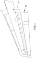
- Figure 1 shows a schematic perspective view of a complete lifting surface having a trailing edge (10) and a control surface (11) being two movable discontinuities (1) located in the trailing edge (10) of the lifting surface, therefore upstream the control surface (11) in the direction of the coming flow. Additionally, two openings (3) are also shown.
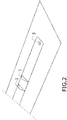
- Figure 2 shows a schematic perspective view of a a part of the surface of the lifting surface shown in figure 1 .
- openings (3) Another possibility would be having more than two openings (3) and controlling the opening and closing of the openings (3) to allow the activation of only some of the movable discontinuities (1).
- the opening and closing of the openings (3) can be made actively or passively, i.e. the openings can be activated by an order or by passive means related to the pressure gradient.
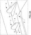
- Figure 3 shows the spanwise conduit (2) and a first embodiment of the discontinuities (1).
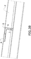
- Figure 3A shows the movable discontinuity (1) in an active position and figure 3B in a pasive position.
- the movable discontinuity (1) comprises a first part (4) movable between an active position in which it is deployed from the surface of the lifting surface and a passive position in which it is located into a recess of the lifting surface keeping the continuity of the skin as shown in figure 3B .
- the movable discontinuity (1) comprises a hinge line (5) for moving the first part (4) between the active and passive positions.
- the movable discontinuity (1) further comprises a second part (6) movable between an active position in which it is located in the recess of the lifting surface thus covering said recess and a passive position in which it is located into the conduit (2). Said second part (6) therefore covers the orifice leaved by the deployment of the first part (4) and therefore when the vortex generator is out of the recess, said recess remains covered.
- the air flowing in the interior of the conduit (2) pushes the first part (4) to be deployed and therefore it acts as a vortex generator.
- a philosophy with "stops" can be implemented to avoid over rotation beyond the active or passive positions of the movable discontinuity, like, for instance, to include some marks on the lifting surface.
- Vortex generators shapes can be different, i.e., rectangular, triangular, ogive, parabolic, gothic, inverse triangular, ... and the figures included are only representative of a possible shape, not being limited to this.
- Figures 4 and 5 show another embodiment of the movable discontinuities (1).
- the discontinuity (1) comprises a part of a flexible skin (7) of the lifting surface, said flexible skin (7) being movable between a passive position in which it is located flush with the rest of the theoretical profile of the lifting surface and an active position in which it departs from the surface of the lifting surface.
- the flexible skin (7) is sucked in forming a recess into the surface of the lifting surface and thus forming a vortex generator.
- the recess is formed between two consecutive ribs (8) of the trailing edge (10) in the embodiment shown in figure 4 .
- the vortex generators are not “bumps” going out but “depressions” produced by an internal suction due to the lower pressure inside the conduit (2).
- the pressure decreases due to the air current and therefore the pressure inside the conduit (2) is less than outside it.
- the openings (3) would preferably be located in the surface of the lifting surface having a negative pressure gradient or what is the same, wherein the suction pressures are produced instead than in the positive pressures face of the lifting surface.
Landscapes
- Engineering & Computer Science (AREA)
- Aviation & Aerospace Engineering (AREA)
- Structures Of Non-Positive Displacement Pumps (AREA)
- Types And Forms Of Lifts (AREA)
- Invalid Beds And Related Equipment (AREA)
Abstract
• a movable discontinuity (1) located in the surface of the lifting surface, the movable discontinuity (1) being movable between:
o an active position in which the movable discontinuity (1) acts as vortex generator, and
o a passive position in which the movable discontinuity (1) is integrated into the surface of the lifting surface,
• a conduit (2) located in the spanwise direction of the lifting surface and in communication with the movable discontinuity (1), the lifting surface comprising at least two openings (3) in its surface spanwise distant from each other in communication with the conduit (2),
the movable discontinuity (1) and the conduit (2) being configured such that when an airflow goes through the conduit (2), this airflow activates the movable discontinuity (1) to act as a vortex generator of the lifting surface.
Description
- The invention is related to a lifting surface having vortex generators in its surface.
- A vortex generator is an aerodynamic surface, consisting of a small vane or bump that creates a vortex. Vortex generators delay flow separation and aerodynamic stalling thus improving the effectiveness of lifting/control surfaces.
- Vortex generators are positioned in such a way that they have an angle of attack with respect to the local airflow. A vortex generator creates a tip vortex which draws energetic, rapidly-moving air from outside the slow-moving boundary layer into contact with the aircraft skin. The boundary layer normally thickens as it moves along the aircraft surface, reducing the effectiveness of trailing-edge control surfaces. Vortex generators can be used to remedy this problem, among others, by re-energizing the boundary layer allowing the airfoil to operate at higher angles-of-attack without airflow separation.
- In terms of aircraft operability, the main benefits of using these devices apply to:
- Increment in maximum take-off weight.
- Increment in maximum landing weight.
- Aircraft noise reduction.
- Efficiency increment of aircraft control surfaces.
- Although vortex generators are known and have been used for over many years, they continue being one of the most effective flow control devices. Nevertheless, it is also known that if they are fixed for improving performance in one flight regimen, they use to penalize the performance in other operational conditions.
- The control surface object of the invention comprises:
- a movable discontinuity located in the surface of the lifting surface; the movable discontinuity being movable between:
- o an active position in which the movable discontinuity acts as vortex generator, and
- o a passive position in which the movable discontinuity is integrated into the surface of the lifting surface without acting as vortex generator,
- a conduit located in the spanwise direction of the lifting surface and being located in communication with the movable discontinuity, the lifting surface comprising at least two openings in its surface spanwise distant from each other in communication with the conduit such that when the openings are open an airflow enters through one of the openings and exits from the other opening,
- The circulation of said airflow is possible both due to an active opening and closing of the openings or through a passive action due to the existence of a spanwise pressure gradient in the upper and lower faces of the lifting surface.
- The openings are preferably located in the trailing edge. As the two openings are spanwise separated a given distance, when the openings are open, due to the aforementioned pressure gradient, an airflow goes along the conduit. An internal air current is created by pressure difference between two "trailing edge" span positions with openings.
- To complete the description and in order to provide for a better understanding of the invention, a set of drawings is provided. Said drawings form an integral part of the description and illustrate preferred embodiments of the invention. The drawings comprise the following figures.
-
Figure 1 shows a schematic perspective view of a lifting surface having a trailing edge and a control surface. -
Figure 2 shows a schematic perspective view of a part of the surface of a lifting surface. -
Figures 3A and3B show a schematic perspective view of a cross section of a first embodiment of the discontinuities and its conduit. -
Figure 4 shows a schematic perspective view from the upper face of the upper skin of a lifting surface showing another embodiment of two movable discontinuities in an active position. -
Figure 5 shows a schematic transversal view of two movable discontinuities in an active and a passive position. -
Figure 6 shows an aircraft having a lifting surface according to the invention. -
Figure 1 shows a schematic perspective view of a complete lifting surface having a trailing edge (10) and a control surface (11) being two movable discontinuities (1) located in the trailing edge (10) of the lifting surface, therefore upstream the control surface (11) in the direction of the coming flow. Additionally, two openings (3) are also shown.Figure 2 shows a schematic perspective view of a a part of the surface of the lifting surface shown infigure 1 . - Another possibility would be having more than two openings (3) and controlling the opening and closing of the openings (3) to allow the activation of only some of the movable discontinuities (1). The opening and closing of the openings (3) can be made actively or passively, i.e. the openings can be activated by an order or by passive means related to the pressure gradient.
-
Figure 3 shows the spanwise conduit (2) and a first embodiment of the discontinuities (1).Figure 3A shows the movable discontinuity (1) in an active position andfigure 3B in a pasive position. - The movable discontinuity (1) comprises a first part (4) movable between an active position in which it is deployed from the surface of the lifting surface and a passive position in which it is located into a recess of the lifting surface keeping the continuity of the skin as shown in
figure 3B . The movable discontinuity (1) comprises a hinge line (5) for moving the first part (4) between the active and passive positions. - The movable discontinuity (1) further comprises a second part (6) movable between an active position in which it is located in the recess of the lifting surface thus covering said recess and a passive position in which it is located into the conduit (2). Said second part (6) therefore covers the orifice leaved by the deployment of the first part (4) and therefore when the vortex generator is out of the recess, said recess remains covered.
- The air flowing in the interior of the conduit (2) pushes the first part (4) to be deployed and therefore it acts as a vortex generator. In case of being needed, a philosophy with "stops" can be implemented to avoid over rotation beyond the active or passive positions of the movable discontinuity, like, for instance, to include some marks on the lifting surface.
- Vortex generators shapes can be different, i.e., rectangular, triangular, ogive, parabolic, gothic, inverse triangular, ... and the figures included are only representative of a possible shape, not being limited to this.
-
Figures 4 and 5 show another embodiment of the movable discontinuities (1). - The discontinuity (1) comprises a part of a flexible skin (7) of the lifting surface, said flexible skin (7) being movable between a passive position in which it is located flush with the rest of the theoretical profile of the lifting surface and an active position in which it departs from the surface of the lifting surface.
- In the shown embodiment, the flexible skin (7) is sucked in forming a recess into the surface of the lifting surface and thus forming a vortex generator. Particularly, the recess is formed between two consecutive ribs (8) of the trailing edge (10) in the embodiment shown in
figure 4 . - In this embodiment the vortex generators are not "bumps" going out but "depressions" produced by an internal suction due to the lower pressure inside the conduit (2). When the air moves into the conduit (2), the pressure decreases due to the air current and therefore the pressure inside the conduit (2) is less than outside it.
- Once the internal suction disappears, the skin that is flexible enough to allow the deformation but stiff enough to accept the pretension, returns to the equilibrium position as can be seen in
figure 5 . - The openings (3) would preferably be located in the surface of the lifting surface having a negative pressure gradient or what is the same, wherein the suction pressures are produced instead than in the positive pressures face of the lifting surface.
Claims (11)
- Lifting surface characterised in that it comprises:• a movable discontinuity (1) located in the surface of the lifting surface, the movable discontinuity (1) being movable between:o an active position in which the movable discontinuity (1) acts as vortex generator, ando a passive position in which the movable discontinuity (1) is integrated into the surface of the lifting surface without acting as vortex generator,• a conduit (2) located in the spanwise direction of the lifting surface and being located in communication with the movable discontinuity (1), the lifting surface comprising at least two openings (3) in its surface spanwise distant from each other in communication with the conduit (2) arranged such that when the openings (3) are open an airflow enters through one of the openings (3) and exits from the other opening (3),the movable discontinuity (1) and the conduit (2) being configured such that when an airflow goes through the conduit (2), this airflow activates the movable discontinuity (1) to act as a vortex generator of the lifting surface.
- Lifting surface, according to claim 1, wherein the movable discontinuity (1) is located in the trailing edge (10) of the lifting surface.
- Lifting surface, according to any preceding claim, wherein it comprises a plurality of openings (3) in its surface spanwise distant from each other in communication with the conduit (2).
- Lifting surface, according to any preceding claim, wherein the openings (3) are located in the surface of the lifting surface having a negative pressure gradient.
- Lifting surface, according to any preceding claim, wherein the movable discontinuity (1) comprises a first part (4) movable between the active position in which it is deployed from the surface of the lifting surface and a passive position in which it is located into a recess of the lifting surface.
- Lifting surface, according to claim 5, wherein the movable discontinuity (1) comprises a hinge line (5) for moving the first part (4) between the active and passive positions.
- Lifting surface, according to any preceding claim 5 or 6, wherein the movable discontinuity (1) further comprises a second part (6) rigidly connected to the first part (4) and movable between the active position in which it is located in a recess of the lifting surface covering said recess and a passive position in which it is located into the conduit (2).
- Lifting surface, according to any preceding claim 1 to 5, wherein the discontinuity (1) comprises a part of a flexible skin of the surface of the lifting surface, said flexible skin (7) being movable between the pasive position in which the flexible skin (7) is located following the aerodynamic profile of the lifting surface and the active position in which the flexible skin (7) departs from the aerodynamic surface of the lifting surface to act as a vortex generator.
- Lifting surface, according to claim 8, wherein the flexible skin (7) is sucked in into a recess in the surface of the lifting surface.
- Lifting surface, according to claim 9, wherein the recess is located between two consecutive ribs (8).
- Aircraft, comprising a lifting surface according to any preceding claim.
Priority Applications (4)
| Application Number | Priority Date | Filing Date | Title |
|---|---|---|---|
| EP17382018.4A EP3348471B1 (en) | 2017-01-17 | 2017-01-17 | Lifting surface |
| ES17382018T ES2761024T3 (en) | 2017-01-17 | 2017-01-17 | Lifting surface |
| CN201810036685.3A CN108482647B (en) | 2017-01-17 | 2018-01-15 | Lifting surface |
| US15/872,460 US11052996B2 (en) | 2017-01-17 | 2018-01-16 | Lifting surface |
Applications Claiming Priority (1)
| Application Number | Priority Date | Filing Date | Title |
|---|---|---|---|
| EP17382018.4A EP3348471B1 (en) | 2017-01-17 | 2017-01-17 | Lifting surface |
Publications (2)
| Publication Number | Publication Date |
|---|---|
| EP3348471A1 true EP3348471A1 (en) | 2018-07-18 |
| EP3348471B1 EP3348471B1 (en) | 2019-09-04 |
Family
ID=57838307
Family Applications (1)
| Application Number | Title | Priority Date | Filing Date |
|---|---|---|---|
| EP17382018.4A Active EP3348471B1 (en) | 2017-01-17 | 2017-01-17 | Lifting surface |
Country Status (4)
| Country | Link |
|---|---|
| US (1) | US11052996B2 (en) |
| EP (1) | EP3348471B1 (en) |
| CN (1) | CN108482647B (en) |
| ES (1) | ES2761024T3 (en) |
Families Citing this family (2)
| Publication number | Priority date | Publication date | Assignee | Title |
|---|---|---|---|---|
| US11149766B2 (en) * | 2018-08-24 | 2021-10-19 | Quest Engines, LLC | Controlled turbulence system |
| CN111619789B (en) * | 2020-05-08 | 2021-10-08 | 中国科学院空天信息创新研究院 | Device and method for controlling airflow on upper surface of blade |
Citations (3)
| Publication number | Priority date | Publication date | Assignee | Title |
|---|---|---|---|---|
| US3586267A (en) * | 1967-12-22 | 1971-06-22 | Sundberg Alf M M I | Arrangement in and relating to aircraft |
| US5755408A (en) * | 1995-04-03 | 1998-05-26 | Schmidt; Robert N. | Fluid flow control devices |
| WO1999050141A1 (en) * | 1998-03-30 | 1999-10-07 | Orbital Research Inc. | Deployable flow control device |
Family Cites Families (9)
| Publication number | Priority date | Publication date | Assignee | Title |
|---|---|---|---|---|
| US2951662A (en) * | 1958-04-21 | 1960-09-06 | Republic Aviat Corp | Boundary layer control means for obtaining high lift for aircraft |
| US3261576A (en) * | 1962-06-14 | 1966-07-19 | Olin Mathieson | Aircraft structure |
| US6209824B1 (en) * | 1997-09-17 | 2001-04-03 | The Boeing Company | Control surface for an aircraft |
| US7748958B2 (en) * | 2006-12-13 | 2010-07-06 | The Boeing Company | Vortex generators on rotor blades to delay an onset of large oscillatory pitching moments and increase maximum lift |
| US8152109B2 (en) * | 2007-11-29 | 2012-04-10 | Silich Bert A | Method and system for controlling fluid flow in relation to a foil and harnessing energy therefrom |
| US9638176B2 (en) * | 2013-05-10 | 2017-05-02 | The Boeing Company | Vortex generator using shape memory alloys |
| US9789956B2 (en) * | 2014-09-19 | 2017-10-17 | The Boeing Company | Vortex generators responsive to ambient conditions |
| DE102015101765A1 (en) * | 2015-02-06 | 2016-08-11 | Airbus Operations Gmbh | Vortex generator arrangement |
| US10730611B2 (en) * | 2018-07-02 | 2020-08-04 | Larry Utt | Short take off and landing aircraft with adjustable vortices device |
-
2017
- 2017-01-17 ES ES17382018T patent/ES2761024T3/en active Active
- 2017-01-17 EP EP17382018.4A patent/EP3348471B1/en active Active
-
2018
- 2018-01-15 CN CN201810036685.3A patent/CN108482647B/en active Active
- 2018-01-16 US US15/872,460 patent/US11052996B2/en active Active
Patent Citations (3)
| Publication number | Priority date | Publication date | Assignee | Title |
|---|---|---|---|---|
| US3586267A (en) * | 1967-12-22 | 1971-06-22 | Sundberg Alf M M I | Arrangement in and relating to aircraft |
| US5755408A (en) * | 1995-04-03 | 1998-05-26 | Schmidt; Robert N. | Fluid flow control devices |
| WO1999050141A1 (en) * | 1998-03-30 | 1999-10-07 | Orbital Research Inc. | Deployable flow control device |
Also Published As
| Publication number | Publication date |
|---|---|
| EP3348471B1 (en) | 2019-09-04 |
| ES2761024T3 (en) | 2020-05-18 |
| CN108482647A (en) | 2018-09-04 |
| CN108482647B (en) | 2022-09-09 |
| US20180201361A1 (en) | 2018-07-19 |
| US11052996B2 (en) | 2021-07-06 |
Similar Documents
| Publication | Publication Date | Title |
|---|---|---|
| US9278753B2 (en) | Wing for an aircraft, aircraft and method for reducing aerodynamic drag and improving maximum lift | |
| US9908617B2 (en) | Active flow control for transonic flight | |
| US10906631B2 (en) | Lifting surface | |
| CN104703878B (en) | There is the aircraft wing of the system forming laminar boundary flow | |
| US20050230565A1 (en) | Arrangement for generating vortexes | |
| EP2316728A2 (en) | Prismatic-shaped vortex generators | |
| US6123296A (en) | Self-actuated flow control system | |
| EP2886453B1 (en) | Boundary layer control system and aircraft having such a boundary layer control system | |
| ES2991416T3 (en) | Blade vortex generator | |
| WO2015198296A2 (en) | Air intake structure and airflow control system | |
| US20170217568A1 (en) | Flow Body For An Aircraft For Passive Boundary Layer Suction | |
| EP1931566B1 (en) | Oscillating vane actuator apparatus and method for active flow control | |
| US20160031550A1 (en) | Submerged vortex generator | |
| WO2008057586A2 (en) | Oscillating vane actuator apparatus and method for active flow control | |
| EP2242685B2 (en) | Improved slat configuration for fixed-wing aircraft | |
| EP3348471B1 (en) | Lifting surface | |
| US9803619B2 (en) | Wind turbine blade and method of controlling the lift of such a blade | |
| US11453477B2 (en) | Wing leading edge device and a wing having such a wing leading edge device | |
| US20070029403A1 (en) | Dual point active flow control system for controlling air vehicle attitude during transonic flight | |
| US10919614B2 (en) | Airfoil with a main wing and a high-lift body | |
| US20230286647A1 (en) | Leading edge flap |
Legal Events
| Date | Code | Title | Description |
|---|---|---|---|
| PUAI | Public reference made under article 153(3) epc to a published international application that has entered the european phase |
Free format text: ORIGINAL CODE: 0009012 |
|
| STAA | Information on the status of an ep patent application or granted ep patent |
Free format text: STATUS: THE APPLICATION HAS BEEN PUBLISHED |
|
| AK | Designated contracting states |
Kind code of ref document: A1 Designated state(s): AL AT BE BG CH CY CZ DE DK EE ES FI FR GB GR HR HU IE IS IT LI LT LU LV MC MK MT NL NO PL PT RO RS SE SI SK SM TR |
|
| AX | Request for extension of the european patent |
Extension state: BA ME |
|
| STAA | Information on the status of an ep patent application or granted ep patent |
Free format text: STATUS: REQUEST FOR EXAMINATION WAS MADE |
|
| 17P | Request for examination filed |
Effective date: 20181221 |
|
| RBV | Designated contracting states (corrected) |
Designated state(s): AL AT BE BG CH CY CZ DE DK EE ES FI FR GB GR HR HU IE IS IT LI LT LU LV MC MK MT NL NO PL PT RO RS SE SI SK SM TR |
|
| GRAP | Despatch of communication of intention to grant a patent |
Free format text: ORIGINAL CODE: EPIDOSNIGR1 |
|
| STAA | Information on the status of an ep patent application or granted ep patent |
Free format text: STATUS: GRANT OF PATENT IS INTENDED |
|
| RIC1 | Information provided on ipc code assigned before grant |
Ipc: B64C 23/06 20060101AFI20190226BHEP |
|
| INTG | Intention to grant announced |
Effective date: 20190402 |
|
| GRAS | Grant fee paid |
Free format text: ORIGINAL CODE: EPIDOSNIGR3 |
|
| GRAA | (expected) grant |
Free format text: ORIGINAL CODE: 0009210 |
|
| STAA | Information on the status of an ep patent application or granted ep patent |
Free format text: STATUS: THE PATENT HAS BEEN GRANTED |
|
| AK | Designated contracting states |
Kind code of ref document: B1 Designated state(s): AL AT BE BG CH CY CZ DE DK EE ES FI FR GB GR HR HU IE IS IT LI LT LU LV MC MK MT NL NO PL PT RO RS SE SI SK SM TR |
|
| REG | Reference to a national code |
Ref country code: GB Ref legal event code: FG4D |
|
| REG | Reference to a national code |
Ref country code: CH Ref legal event code: EP |
|
| REG | Reference to a national code |
Ref country code: AT Ref legal event code: REF Ref document number: 1174981 Country of ref document: AT Kind code of ref document: T Effective date: 20190915 |
|
| REG | Reference to a national code |
Ref country code: DE Ref legal event code: R096 Ref document number: 602017006771 Country of ref document: DE |
|
| REG | Reference to a national code |
Ref country code: IE Ref legal event code: FG4D |
|
| REG | Reference to a national code |
Ref country code: NL Ref legal event code: MP Effective date: 20190904 |
|
| REG | Reference to a national code |
Ref country code: LT Ref legal event code: MG4D |
|
| PG25 | Lapsed in a contracting state [announced via postgrant information from national office to epo] |
Ref country code: NO Free format text: LAPSE BECAUSE OF FAILURE TO SUBMIT A TRANSLATION OF THE DESCRIPTION OR TO PAY THE FEE WITHIN THE PRESCRIBED TIME-LIMIT Effective date: 20191204 Ref country code: FI Free format text: LAPSE BECAUSE OF FAILURE TO SUBMIT A TRANSLATION OF THE DESCRIPTION OR TO PAY THE FEE WITHIN THE PRESCRIBED TIME-LIMIT Effective date: 20190904 Ref country code: LT Free format text: LAPSE BECAUSE OF FAILURE TO SUBMIT A TRANSLATION OF THE DESCRIPTION OR TO PAY THE FEE WITHIN THE PRESCRIBED TIME-LIMIT Effective date: 20190904 Ref country code: HR Free format text: LAPSE BECAUSE OF FAILURE TO SUBMIT A TRANSLATION OF THE DESCRIPTION OR TO PAY THE FEE WITHIN THE PRESCRIBED TIME-LIMIT Effective date: 20190904 Ref country code: BG Free format text: LAPSE BECAUSE OF FAILURE TO SUBMIT A TRANSLATION OF THE DESCRIPTION OR TO PAY THE FEE WITHIN THE PRESCRIBED TIME-LIMIT Effective date: 20191204 Ref country code: SE Free format text: LAPSE BECAUSE OF FAILURE TO SUBMIT A TRANSLATION OF THE DESCRIPTION OR TO PAY THE FEE WITHIN THE PRESCRIBED TIME-LIMIT Effective date: 20190904 |
|
| PG25 | Lapsed in a contracting state [announced via postgrant information from national office to epo] |
Ref country code: GR Free format text: LAPSE BECAUSE OF FAILURE TO SUBMIT A TRANSLATION OF THE DESCRIPTION OR TO PAY THE FEE WITHIN THE PRESCRIBED TIME-LIMIT Effective date: 20191205 Ref country code: AL Free format text: LAPSE BECAUSE OF FAILURE TO SUBMIT A TRANSLATION OF THE DESCRIPTION OR TO PAY THE FEE WITHIN THE PRESCRIBED TIME-LIMIT Effective date: 20190904 Ref country code: LV Free format text: LAPSE BECAUSE OF FAILURE TO SUBMIT A TRANSLATION OF THE DESCRIPTION OR TO PAY THE FEE WITHIN THE PRESCRIBED TIME-LIMIT Effective date: 20190904 Ref country code: RS Free format text: LAPSE BECAUSE OF FAILURE TO SUBMIT A TRANSLATION OF THE DESCRIPTION OR TO PAY THE FEE WITHIN THE PRESCRIBED TIME-LIMIT Effective date: 20190904 |
|
| REG | Reference to a national code |
Ref country code: AT Ref legal event code: MK05 Ref document number: 1174981 Country of ref document: AT Kind code of ref document: T Effective date: 20190904 |
|
| PG25 | Lapsed in a contracting state [announced via postgrant information from national office to epo] |
Ref country code: RO Free format text: LAPSE BECAUSE OF FAILURE TO SUBMIT A TRANSLATION OF THE DESCRIPTION OR TO PAY THE FEE WITHIN THE PRESCRIBED TIME-LIMIT Effective date: 20190904 Ref country code: IT Free format text: LAPSE BECAUSE OF FAILURE TO SUBMIT A TRANSLATION OF THE DESCRIPTION OR TO PAY THE FEE WITHIN THE PRESCRIBED TIME-LIMIT Effective date: 20190904 Ref country code: PT Free format text: LAPSE BECAUSE OF FAILURE TO SUBMIT A TRANSLATION OF THE DESCRIPTION OR TO PAY THE FEE WITHIN THE PRESCRIBED TIME-LIMIT Effective date: 20200106 Ref country code: PL Free format text: LAPSE BECAUSE OF FAILURE TO SUBMIT A TRANSLATION OF THE DESCRIPTION OR TO PAY THE FEE WITHIN THE PRESCRIBED TIME-LIMIT Effective date: 20190904 Ref country code: AT Free format text: LAPSE BECAUSE OF FAILURE TO SUBMIT A TRANSLATION OF THE DESCRIPTION OR TO PAY THE FEE WITHIN THE PRESCRIBED TIME-LIMIT Effective date: 20190904 Ref country code: NL Free format text: LAPSE BECAUSE OF FAILURE TO SUBMIT A TRANSLATION OF THE DESCRIPTION OR TO PAY THE FEE WITHIN THE PRESCRIBED TIME-LIMIT Effective date: 20190904 Ref country code: EE Free format text: LAPSE BECAUSE OF FAILURE TO SUBMIT A TRANSLATION OF THE DESCRIPTION OR TO PAY THE FEE WITHIN THE PRESCRIBED TIME-LIMIT Effective date: 20190904 |
|
| REG | Reference to a national code |
Ref country code: ES Ref legal event code: FG2A Ref document number: 2761024 Country of ref document: ES Kind code of ref document: T3 Effective date: 20200518 |
|
| PG25 | Lapsed in a contracting state [announced via postgrant information from national office to epo] |
Ref country code: CZ Free format text: LAPSE BECAUSE OF FAILURE TO SUBMIT A TRANSLATION OF THE DESCRIPTION OR TO PAY THE FEE WITHIN THE PRESCRIBED TIME-LIMIT Effective date: 20190904 Ref country code: SM Free format text: LAPSE BECAUSE OF FAILURE TO SUBMIT A TRANSLATION OF THE DESCRIPTION OR TO PAY THE FEE WITHIN THE PRESCRIBED TIME-LIMIT Effective date: 20190904 Ref country code: SK Free format text: LAPSE BECAUSE OF FAILURE TO SUBMIT A TRANSLATION OF THE DESCRIPTION OR TO PAY THE FEE WITHIN THE PRESCRIBED TIME-LIMIT Effective date: 20190904 Ref country code: IS Free format text: LAPSE BECAUSE OF FAILURE TO SUBMIT A TRANSLATION OF THE DESCRIPTION OR TO PAY THE FEE WITHIN THE PRESCRIBED TIME-LIMIT Effective date: 20200224 |
|
| REG | Reference to a national code |
Ref country code: DE Ref legal event code: R097 Ref document number: 602017006771 Country of ref document: DE |
|
| PLBE | No opposition filed within time limit |
Free format text: ORIGINAL CODE: 0009261 |
|
| STAA | Information on the status of an ep patent application or granted ep patent |
Free format text: STATUS: NO OPPOSITION FILED WITHIN TIME LIMIT |
|
| PG2D | Information on lapse in contracting state deleted |
Ref country code: IS |
|
| PG25 | Lapsed in a contracting state [announced via postgrant information from national office to epo] |
Ref country code: DK Free format text: LAPSE BECAUSE OF FAILURE TO SUBMIT A TRANSLATION OF THE DESCRIPTION OR TO PAY THE FEE WITHIN THE PRESCRIBED TIME-LIMIT Effective date: 20190904 Ref country code: IS Free format text: LAPSE BECAUSE OF FAILURE TO SUBMIT A TRANSLATION OF THE DESCRIPTION OR TO PAY THE FEE WITHIN THE PRESCRIBED TIME-LIMIT Effective date: 20200105 |
|
| 26N | No opposition filed |
Effective date: 20200605 |
|
| PG25 | Lapsed in a contracting state [announced via postgrant information from national office to epo] |
Ref country code: SI Free format text: LAPSE BECAUSE OF FAILURE TO SUBMIT A TRANSLATION OF THE DESCRIPTION OR TO PAY THE FEE WITHIN THE PRESCRIBED TIME-LIMIT Effective date: 20190904 Ref country code: MC Free format text: LAPSE BECAUSE OF FAILURE TO SUBMIT A TRANSLATION OF THE DESCRIPTION OR TO PAY THE FEE WITHIN THE PRESCRIBED TIME-LIMIT Effective date: 20190904 |
|
| REG | Reference to a national code |
Ref country code: CH Ref legal event code: PL |
|
| REG | Reference to a national code |
Ref country code: BE Ref legal event code: MM Effective date: 20200131 |
|
| PG25 | Lapsed in a contracting state [announced via postgrant information from national office to epo] |
Ref country code: LU Free format text: LAPSE BECAUSE OF NON-PAYMENT OF DUE FEES Effective date: 20200117 |
|
| PG25 | Lapsed in a contracting state [announced via postgrant information from national office to epo] |
Ref country code: CH Free format text: LAPSE BECAUSE OF NON-PAYMENT OF DUE FEES Effective date: 20200131 Ref country code: BE Free format text: LAPSE BECAUSE OF NON-PAYMENT OF DUE FEES Effective date: 20200131 Ref country code: LI Free format text: LAPSE BECAUSE OF NON-PAYMENT OF DUE FEES Effective date: 20200131 |
|
| PG25 | Lapsed in a contracting state [announced via postgrant information from national office to epo] |
Ref country code: IE Free format text: LAPSE BECAUSE OF NON-PAYMENT OF DUE FEES Effective date: 20200117 |
|
| REG | Reference to a national code |
Ref country code: ES Ref legal event code: FD2A Effective date: 20210602 |
|
| PG25 | Lapsed in a contracting state [announced via postgrant information from national office to epo] |
Ref country code: ES Free format text: LAPSE BECAUSE OF NON-PAYMENT OF DUE FEES Effective date: 20200118 |
|
| PG25 | Lapsed in a contracting state [announced via postgrant information from national office to epo] |
Ref country code: TR Free format text: LAPSE BECAUSE OF FAILURE TO SUBMIT A TRANSLATION OF THE DESCRIPTION OR TO PAY THE FEE WITHIN THE PRESCRIBED TIME-LIMIT Effective date: 20190904 Ref country code: MT Free format text: LAPSE BECAUSE OF FAILURE TO SUBMIT A TRANSLATION OF THE DESCRIPTION OR TO PAY THE FEE WITHIN THE PRESCRIBED TIME-LIMIT Effective date: 20190904 Ref country code: CY Free format text: LAPSE BECAUSE OF FAILURE TO SUBMIT A TRANSLATION OF THE DESCRIPTION OR TO PAY THE FEE WITHIN THE PRESCRIBED TIME-LIMIT Effective date: 20190904 |
|
| PG25 | Lapsed in a contracting state [announced via postgrant information from national office to epo] |
Ref country code: MK Free format text: LAPSE BECAUSE OF FAILURE TO SUBMIT A TRANSLATION OF THE DESCRIPTION OR TO PAY THE FEE WITHIN THE PRESCRIBED TIME-LIMIT Effective date: 20190904 |
|
| PGFP | Annual fee paid to national office [announced via postgrant information from national office to epo] |
Ref country code: GB Payment date: 20260123 Year of fee payment: 10 |
|
| PGFP | Annual fee paid to national office [announced via postgrant information from national office to epo] |
Ref country code: DE Payment date: 20260121 Year of fee payment: 10 |
|
| PGFP | Annual fee paid to national office [announced via postgrant information from national office to epo] |
Ref country code: FR Payment date: 20260123 Year of fee payment: 10 |