EP3348470A1 - Configuration of a t junction of a flow obstacle on a wall bounding a flow - Google Patents
Configuration of a t junction of a flow obstacle on a wall bounding a flow Download PDFInfo
- Publication number
- EP3348470A1 EP3348470A1 EP17151606.5A EP17151606A EP3348470A1 EP 3348470 A1 EP3348470 A1 EP 3348470A1 EP 17151606 A EP17151606 A EP 17151606A EP 3348470 A1 EP3348470 A1 EP 3348470A1
- Authority
- EP
- European Patent Office
- Prior art keywords
- flow
- junction
- obstacle
- concavity
- wall
- Prior art date
- Legal status (The legal status is an assumption and is not a legal conclusion. Google has not performed a legal analysis and makes no representation as to the accuracy of the status listed.)
- Granted
Links
Images

Classifications
-
- B—PERFORMING OPERATIONS; TRANSPORTING
- B64—AIRCRAFT; AVIATION; COSMONAUTICS
- B64C—AEROPLANES; HELICOPTERS
- B64C1/00—Fuselages; Constructional features common to fuselages, wings, stabilising surfaces or the like
- B64C1/26—Attaching the wing or tail units or stabilising surfaces
-
- B—PERFORMING OPERATIONS; TRANSPORTING
- B64—AIRCRAFT; AVIATION; COSMONAUTICS
- B64C—AEROPLANES; HELICOPTERS
- B64C1/00—Fuselages; Constructional features common to fuselages, wings, stabilising surfaces or the like
- B64C1/36—Fuselages; Constructional features common to fuselages, wings, stabilising surfaces or the like adapted to receive antennas or radomes
-
- B—PERFORMING OPERATIONS; TRANSPORTING
- B64—AIRCRAFT; AVIATION; COSMONAUTICS
- B64C—AEROPLANES; HELICOPTERS
- B64C21/00—Influencing air flow over aircraft surfaces by affecting boundary layer flow
-
- B—PERFORMING OPERATIONS; TRANSPORTING
- B64—AIRCRAFT; AVIATION; COSMONAUTICS
- B64D—EQUIPMENT FOR FITTING IN OR TO AIRCRAFT; FLIGHT SUITS; PARACHUTES; ARRANGEMENT OR MOUNTING OF POWER PLANTS OR PROPULSION TRANSMISSIONS IN AIRCRAFT
- B64D27/00—Arrangement or mounting of power plants in aircraft; Aircraft characterised by the type or position of power plants
- B64D27/02—Aircraft characterised by the type or position of power plants
-
- Y—GENERAL TAGGING OF NEW TECHNOLOGICAL DEVELOPMENTS; GENERAL TAGGING OF CROSS-SECTIONAL TECHNOLOGIES SPANNING OVER SEVERAL SECTIONS OF THE IPC; TECHNICAL SUBJECTS COVERED BY FORMER USPC CROSS-REFERENCE ART COLLECTIONS [XRACs] AND DIGESTS
- Y02—TECHNOLOGIES OR APPLICATIONS FOR MITIGATION OR ADAPTATION AGAINST CLIMATE CHANGE
- Y02T—CLIMATE CHANGE MITIGATION TECHNOLOGIES RELATED TO TRANSPORTATION
- Y02T50/00—Aeronautics or air transport
- Y02T50/10—Drag reduction
Definitions
- the present invention relates to a T junction of a flow obstacle on a wall bounding a flow, the flow having a main flow direction.
- the present invention relates to a T junction comprising a concavity of the wall neighboring the flow obstacle, the concavity terminating at a first distance downstream the flow obstacle.
- the flow obstacle may, for example, be a wing attached to a fuselage of an airplane, the wall bounding the flow being the wall of the airplane.
- US 2009/0078830 A1 discloses an aircraft including a fuselage and two wings to which engine nacelles are attached and that are each connected laterally to the fuselage on each side thereof by a central fairing.
- the central fairing includes, facing each wing, two opposed surfaces connected one to a suction face side and the other to a pressure face side of the wing and that extend longitudinally along the fuselage.
- At least one of the two surfaces include at least one local geometric deformation configured to generate lateral aerodynamic disturbances on the central fairing towards the wing to control the flow of air over the wing.
- These geometric deformations have a form of a local concavity or hollow extending primarily in the longitudinal direction of the fuselage and secondarily in a direction perpendicular thereto.
- lateral perturbations are created that propagate from the central fairing towards the wing tip and have the form of compression waves of the flow, initiating a weak shock.
- the pressure waves are generated to make it possible to reorganize the pressure field over the wing structure at a distance, particularly after replacing the existing engines of the airplane by larger engines resulting in some degradation of the aerodynamic performances of the remotorized airplane.
- US patent 6,149,101 discloses a wing in combination with a fuselage having a body which is elongated in the direction of flight.
- the body has an indentation proximate the wing.
- the body indentation is adapted to a wing thickening in the direction of flight to minimize a variation of the combined volume of the body and the wing in the direction of flight to reduce a combined volume wave drag.
- the present invention provides a T junction comprising the feature of independent claim 1.
- Dependent claims 2 to 11 are directed to preferred embodiments of the T junction.
- Claims 12 to 14 are related to airplanes comprising the T junction, and claim 15 is related to a vehicle comprising the T junction.
- the starting point of the present invention is a T junction of a flow obstacle on a wall bounding a flow, the flow having a main flow direction.
- the flow along the wall forms a boundary layer.
- an adverse pressure gradient is caused which results in a reversal and a separation of the flow.
- the boundary layer rolls up and forms what is known as a horse shoe vortex.
- the horse shoe vortex is then convected downstream of the obstacle by the flow.
- the horse shoe vortex contributes to the drag with an additional component known as interference drag.
- the T junction according to the invention comprises a concavity of the wall neighboring the flow obstacle.
- This concavity starts at a distance upstream the flow obstacle in the main flow direction and terminates at a same or other distance downstream the flow obstacle in the main flow direction.
- the invention is a concave shape wall contour serving for passive drag-reduction.
- the concavity acts favorably on the flow in the T junction by decreasing the peak vorticity of the horse shoe vortex.
- the concavity accommodates the horse shoe vortex and offers a pocket to the horse shoe vortex in which it stabilizes. This leaves the flow outside the concavity undisturbed, thus lowering the drag of the obstacle in the vicinity of the T junction.
- the concavity effectively increases the boundary layer thickness and decreases the velocity of the flow outside the boundary layer. This, in turn, increases the horse shoe vortex size but lowers the viscous dissipation due to the horse shoe vortex. This reduces the transfer of streamwise momentum to the cross plane of the T junction. Downstream of the flow obstacle, at the end of the concavity, the flow is accelerated due to the concavity shape and the boundary layer gets thinner resulting in less momentum loss than a configuration without concavity.
- the sides of the concavity create counter-rotating vortices whose sense of rotation is opposite to the rotation in the legs of the horse shoe vortex.
- the interaction of these additional vortices in the wake will also reduce the shear experienced by the horse shoe vortex and therefore also leads to reduced dissipation losses.
- the concavity extends beyond the actual intersection of the flow obstacle and the wall, the cavity is shaped in such way that it only influences the flow in the proximity of the T junction.
- the concavity starts at a distance between 20 % and 80 % of a length of the obstacle in the main flow direction upstream of the obstacle leading edge.
- the concavity typically terminates at a distance between 50 % and 110 % of the length of the obstacle in the main flow direction downstream of an obstacle trailing edge.
- the length of the obstacle in the main flow direction is defined as that distance between the most upstream and the most downstream points of that part of the flow obstacle that is attached to the wall.
- the concavity may extend from the flow obstacle up to a distance between 50 % and 100 % of the length of the obstacle in the main flow direction.
- the optimum value of this distance will depend on the shape of the flow obstacle and the size of an disturbance of the flow created by the flow obstacle.
- the wall bounding the flow extends all around the flow obstacle - which may, for example, not be the case with a wing attached to the bottom or the top of the fuselage of an airplane -, the concavity may extend all around the flow obstacle. Then, the two sides of the cavity will create two counter-rotating vortices whose senses of rotation are opposite to the rotation in the legs of the horse shoe vortex.
- a maximum depth of the cavity - which is the maximum depth displayed by the actual cavity - is in a range of 50 % to 200 % of the boundary layer thickness of the flow over the wall upstream the flow obstacle, where it is not yet affected by the flow obstacle.
- the concavity may comprise two overlapping partial concavities both extending along the main flow direction, each on one side of the obstacle.
- a longitudinal ridge may be formed between the overlapping partial concavities.
- the concavity may be a single concavity not subdivided by any ridges.
- a circumference of the concavity in the wall may essentially be a rectangular with rounded edges. This particularly applies to a flow obstacle elongated in the main flow direction.
- a length of such an elongated flow obstacle in the main flow direction may be at least twice a thickness of the flow obstacle transversal to the main flow direction.
- the elongation factor of such an elongated flow obstacle may also be much higher than 2.
- the flow obstacle may however also have any other cross-sectional shape. For example, it may be a cylinder.
- each wing meeting with a wall of the fuselage may form a T junction according to the present invention.
- the T junction according to the present invention may also be designated as an anti-fairing.
- any engine pylon attached to a wing or the fuselage of the airplane and meeting with the wall of the fuselage or the wing may form a T junction according to the present invention.
- any sensor or antenna attached to a wing or the fuselage of the airplane and meeting with the wall of the fuselage or the wing may form a T junction according to the present invention.
- the sensor or antenna meeting with a wall of the body may also form a T junction according to the present invention.
- the concavity according to the present invention is designed for subsonic flow conditions. It may be assumed, however, that the working mechanism will also be effective at transonic flow conditions.
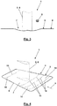
- the T junction 1 schematically depicted in Figs. 1 to 4 may be the junction of a wing 2 on a wall 3 of a fuselage 4 of an airplane.
- the wall 3 bounds a flow having a main flow direction 5, to which the wing 2 is a flow obstacle 6.
- the wall 3 is provided with a concavity 7.
- the concavity 7 extends all around the flow obstacle 6.
- a circumference 8 of the concavity 7 essentially is a rectangular with rounded edges. Upstream of the flow obstacle 6, the concavity 7 starts at a distance 9.
- This distance 9 is in a range of 20 % to 80 % of a length 10 of the flow obstacle 6 in the main flow direction 5. Downstream the flow obstacle 6, the concavity 7 terminates at a distance 11 which is in a range of 50 % to 110 % of the length 10. On both sides of the flow obstacle 6 the concavity 7 laterally extends over distances 12. Although the distances 12 are equal in the figures, they may be different when the flow obstacle 6 is asymmetric, for example.
- a maximum depth 13 of the concavity 7 is in a range of 50 % to 200 % of a boundary layer thickness of the flow before the boundary layer of the flow is affected by the flow obstacle 6.
- the concavity 7 may comprise two overlapping partial concavities 14 separated by a ridge 15 as illustrated by contour lines 16 in Fig. 4 .
Landscapes
- Engineering & Computer Science (AREA)
- Aviation & Aerospace Engineering (AREA)
- Mechanical Engineering (AREA)
- Aerodynamic Tests, Hydrodynamic Tests, Wind Tunnels, And Water Tanks (AREA)
Abstract
Description
- The present invention relates to a T junction of a flow obstacle on a wall bounding a flow, the flow having a main flow direction. Particularly, the present invention relates to a T junction comprising a concavity of the wall neighboring the flow obstacle, the concavity terminating at a first distance downstream the flow obstacle.
- The flow obstacle may, for example, be a wing attached to a fuselage of an airplane, the wall bounding the flow being the wall of the airplane.
- J. Brezillon and R.P. Dwight: Aerodynamic Shape Optimization Using the Discrete Adjoint of the Navier-Strokes Equations: Applications towards Complex 3D Configurations, see https:\\ aerodynamics.lr.tudelft.nl/~rdwight/pub/BreDwi2009.pdf, disclose results of a fuselage drag-minimization optimization. These results include an optimization of the fuselage shape at the wing-body intersection of an airplane, with parts of the flow bounding wall going into the fuselage. These parts start downstream the leading edge of the wing, extend along the upper side of the wing and terminate behind the trailing edge of the wing.
-
US 2009/0078830 A1 discloses an aircraft including a fuselage and two wings to which engine nacelles are attached and that are each connected laterally to the fuselage on each side thereof by a central fairing. The central fairing includes, facing each wing, two opposed surfaces connected one to a suction face side and the other to a pressure face side of the wing and that extend longitudinally along the fuselage. At least one of the two surfaces include at least one local geometric deformation configured to generate lateral aerodynamic disturbances on the central fairing towards the wing to control the flow of air over the wing. These geometric deformations have a form of a local concavity or hollow extending primarily in the longitudinal direction of the fuselage and secondarily in a direction perpendicular thereto. By means of this geometric deformation, lateral perturbations are created that propagate from the central fairing towards the wing tip and have the form of compression waves of the flow, initiating a weak shock. The pressure waves are generated to make it possible to reorganize the pressure field over the wing structure at a distance, particularly after replacing the existing engines of the airplane by larger engines resulting in some degradation of the aerodynamic performances of the remotorized airplane. -
US patent 6,149,101 discloses a wing in combination with a fuselage having a body which is elongated in the direction of flight. The body has an indentation proximate the wing. The body indentation is adapted to a wing thickening in the direction of flight to minimize a variation of the combined volume of the body and the wing in the direction of flight to reduce a combined volume wave drag. - There still is a need of a T junction of a flow obstacle on a wall bounding a flow which, when for example applied in an airplane at the T junctions of the wings on the fuselage, effectively reduces the additional drag due to this junction. The drag, for example of a wing/flat-plate configuration, is higher than the sum of the drag of the corresponding wing alone and the drag of the corresponding flat-plate alone.
- The present invention provides a T junction comprising the feature of
independent claim 1. Dependent claims 2 to 11 are directed to preferred embodiments of the T junction.Claims 12 to 14 are related to airplanes comprising the T junction, andclaim 15 is related to a vehicle comprising the T junction. - The starting point of the present invention is a T junction of a flow obstacle on a wall bounding a flow, the flow having a main flow direction. The flow along the wall forms a boundary layer. When the boundary layer encounters the flow obstacle large enough to stop a part of the flow on the leading edge of the obstacle, an adverse pressure gradient is caused which results in a reversal and a separation of the flow. Due to the separation of the flow, the boundary layer rolls up and forms what is known as a horse shoe vortex. The horse shoe vortex is then convected downstream of the obstacle by the flow. As separated flow, the horse shoe vortex contributes to the drag with an additional component known as interference drag. This interference drag is a reason why, for example, the drag of a wing/flat-plate configuration is higher than the sum of the drag of the corresponding wing alone and of the drag of the corresponding flat-plate alone. To counteract the interference drag caused by the horse shoe vortex, the T junction according to the invention comprises a concavity of the wall neighboring the flow obstacle. This concavity starts at a distance upstream the flow obstacle in the main flow direction and terminates at a same or other distance downstream the flow obstacle in the main flow direction. In other words, the invention is a concave shape wall contour serving for passive drag-reduction. The concavity acts favorably on the flow in the T junction by decreasing the peak vorticity of the horse shoe vortex. The concavity accommodates the horse shoe vortex and offers a pocket to the horse shoe vortex in which it stabilizes. This leaves the flow outside the concavity undisturbed, thus lowering the drag of the obstacle in the vicinity of the T junction. The concavity effectively increases the boundary layer thickness and decreases the velocity of the flow outside the boundary layer. This, in turn, increases the horse shoe vortex size but lowers the viscous dissipation due to the horse shoe vortex. This reduces the transfer of streamwise momentum to the cross plane of the T junction. Downstream of the flow obstacle, at the end of the concavity, the flow is accelerated due to the concavity shape and the boundary layer gets thinner resulting in less momentum loss than a configuration without concavity. Further, the sides of the concavity create counter-rotating vortices whose sense of rotation is opposite to the rotation in the legs of the horse shoe vortex. The interaction of these additional vortices in the wake will also reduce the shear experienced by the horse shoe vortex and therefore also leads to reduced dissipation losses. Although the concavity extends beyond the actual intersection of the flow obstacle and the wall, the cavity is shaped in such way that it only influences the flow in the proximity of the T junction.
- The optimum location and amplitude of the concavity will depend on the fluid dynamic or aerodynamic parameters of the T junction. These parameters are in particular the flow speed, the boundary layer thickness, and the parameters that relate to the junction geometry. Typically, the concavity starts at a distance between 20 % and 80 % of a length of the obstacle in the main flow direction upstream of the obstacle leading edge. The concavity typically terminates at a distance between 50 % and 110 % of the length of the obstacle in the main flow direction downstream of an obstacle trailing edge.
- The length of the obstacle in the main flow direction is defined as that distance between the most upstream and the most downstream points of that part of the flow obstacle that is attached to the wall.
- In at least one transversal direction with regard to the main flow direction, the concavity may extend from the flow obstacle up to a distance between 50 % and 100 % of the length of the obstacle in the main flow direction. The optimum value of this distance will depend on the shape of the flow obstacle and the size of an disturbance of the flow created by the flow obstacle.
- If the wall bounding the flow extends all around the flow obstacle - which may, for example, not be the case with a wing attached to the bottom or the top of the fuselage of an airplane -, the concavity may extend all around the flow obstacle. Then, the two sides of the cavity will create two counter-rotating vortices whose senses of rotation are opposite to the rotation in the legs of the horse shoe vortex.
- The optimum depth of the concavity depends on the boundary layer thickness of the flow over the wall. Typically, a maximum depth of the cavity - which is the maximum depth displayed by the actual cavity - is in a range of 50 % to 200 % of the boundary layer thickness of the flow over the wall upstream the flow obstacle, where it is not yet affected by the flow obstacle.
- In transversal direction with regard to the main flow direction the concavity may comprise two overlapping partial concavities both extending along the main flow direction, each on one side of the obstacle. A longitudinal ridge may be formed between the overlapping partial concavities. Alternatively, the concavity may be a single concavity not subdivided by any ridges.
- A circumference of the concavity in the wall may essentially be a rectangular with rounded edges. This particularly applies to a flow obstacle elongated in the main flow direction. A length of such an elongated flow obstacle in the main flow direction may be at least twice a thickness of the flow obstacle transversal to the main flow direction. The elongation factor of such an elongated flow obstacle may also be much higher than 2. The flow obstacle may however also have any other cross-sectional shape. For example, it may be a cylinder.
- In an airplane comprising a fuselage and two wings attached to the fuselage, each wing meeting with a wall of the fuselage may form a T junction according to the present invention. Here, the T junction according to the present invention may also be designated as an anti-fairing.
- Alternatively or additionally, any engine pylon attached to a wing or the fuselage of the airplane and meeting with the wall of the fuselage or the wing may form a T junction according to the present invention. Even further, any sensor or antenna attached to a wing or the fuselage of the airplane and meeting with the wall of the fuselage or the wing may form a T junction according to the present invention.
- In any other vehicle comprising a sensor or antenna attached to a body of the vehicle, the sensor or antenna meeting with a wall of the body may also form a T junction according to the present invention.
- The concavity according to the present invention is designed for subsonic flow conditions. It may be assumed, however, that the working mechanism will also be effective at transonic flow conditions.
- Advantageous developments of the invention result from the claims, the description and the drawings. The advantages of features and of combinations of a plurality of features mentioned at the beginning of the description only serve as examples and may be used alternatively or cumulatively without the necessity of embodiments according to the invention having to obtain these advantages. Without changing the scope of protection as defined by the enclosed claims, the following applies with respect to the disclosure of the original application and the patent: further features may be taken from the drawings, in particular from the illustrated designs and the dimensions of a plurality of components with respect to one another as well as from their relative arrangement and their operative connection. The combination of features of different embodiments of the invention or of features of different claims independent of the chosen references of the claims is also possible, and it is motivated herewith. This also relates to features which are illustrated in separate drawings, or which are mentioned when describing them. These features may also be combined with features of different claims. Furthermore, it is possible that further embodiments of the invention do not have the features mentioned in the claims.
- The number of the features mentioned in the claims and in the description is to be understood to cover this exact number and a greater number than the mentioned number without having to explicitly use the adverb "at least". For example, if a sensor is mentioned, this is to be understood such that there is exactly one sensor or there are two sensors or more sensors. Additional features may be added to these features, or these features may be the only features of the respective product.
- The reference signs contained in the claims are not limiting the extent of the matter protected by the claims. Their sole function is to make the claims easier to understand.
- In the following, the invention is further explained and described with respect to preferred exemplary embodiments illustrated in the drawings.
- Fig. 1
- is a lateral or transversal view on a T junction according to the present invention.
- Fig. 2
- is a top view on the T junction according to the present invention.
- Fig. 3
- is an upstream front view of the T junction according to the present invention.
- Fig. 4
- is a perspective front view of the T junction according to the present invention.
- The
T junction 1 schematically depicted inFigs. 1 to 4 may be the junction of a wing 2 on awall 3 of afuselage 4 of an airplane. Thewall 3 bounds a flow having amain flow direction 5, to which the wing 2 is a flow obstacle 6. To reduce a so-called interference drag which occurs in addition to the sum of the drags of thewall 3 and the wing 2, thewall 3 is provided with aconcavity 7. Theconcavity 7 extends all around the flow obstacle 6. Acircumference 8 of theconcavity 7 essentially is a rectangular with rounded edges. Upstream of the flow obstacle 6, theconcavity 7 starts at adistance 9. Thisdistance 9 is in a range of 20 % to 80 % of alength 10 of the flow obstacle 6 in themain flow direction 5. Downstream the flow obstacle 6, theconcavity 7 terminates at adistance 11 which is in a range of 50 % to 110 % of thelength 10. On both sides of the flow obstacle 6 theconcavity 7 laterally extends over distances 12. Although thedistances 12 are equal in the figures, they may be different when the flow obstacle 6 is asymmetric, for example. Amaximum depth 13 of theconcavity 7 is in a range of 50 % to 200 % of a boundary layer thickness of the flow before the boundary layer of the flow is affected by the flow obstacle 6. Theconcavity 7 may comprise two overlappingpartial concavities 14 separated by aridge 15 as illustrated bycontour lines 16 inFig. 4 . -
- 1
- T junction
- 2
- wing
- 3
- wall
- 4
- fuselage
- 5
- main flow direction
- 6
- flow obstacle
- 7
- concavity
- 8
- circumference
- 9
- (second) distance
- 10
- length
- 11
- (first) distance
- 12
- (third) distance
- 13
- maximum depth
- 14
- partial concavity
- 15
- ridge
- 16
- contour line
Claims (15)
- A T junction (1) of a flow obstacle (6) on a wall (3) bounding a flow, the flow having a main flow direction (5),- wherein the T junction (1) comprises a concavity (7) of the wall (3) neighboring the flow obstacle (6), the concavity (7) terminating at a first distance (11) downstream the flow obstacle (6) in the main flow direction (5),
characterized in that the concavity (7) starts at a second distance (9) upstream the flow obstacle (6) in the main flow direction (5). - The T junction (1) of claim 1, characterized in that the first distance (11) is in a range of 20 % to 80 % of a length (10) of the flow obstacle (6) in the main flow direction (5) and that the second distance (9) is in a range of 50 % to 110 % of the length (10) of the flow obstacle (6) in the main flow direction (5).
- The T junction (1) of claim 1 or 2, characterized in that the concavity (7), in at least one transversal direction (5) with regard to the main flow direction (5), extends from the flow obstacle (6) up to a third distance (12).
- The T junction (1) of claim 3, characterized in that the third distance (12) is in a range of 50 % to 100 % of a length (10) of the flow obstacle (6) in the main flow direction (5).
- The T junction (1) of claim 2 or 4, characterized in that length (10) of the flow obstacle (6) in the main flow direction (5) is that distance between the most upstream and the most downstream points of that part of the flow obstacle (6) that is attached to the wall (3).
- The T junction (1) of any of the claims 1 to 5, characterized in that the concavity (7) extends all around the flow obstacle (6).
- The T junction (1) of any of the claims 1 to 6, characterized in that a maximum depth (13) of the concavity (7) is in a range of 50 % to 200 % of a boundary layer thickness of the flow over the wall (3) upstream the flow obstacle (6) and not yet affected by the flow obstacle (6).
- The T junction (1) of any of the claims 1 to 7, characterized in that the concavity (7) comprises two overlapping partial concavities (14) both extending along the main flow direction (5).
- The T junction (1) of any of the claims 1 to 8, characterized in that a circumference (8) of the concavity (7) is a rectangular with rounded edges.
- The T junction (1) of any of the claims 1 to 9, characterized in that the flow obstacle (6) is elongated in the main flow direction (5).
- The T junction (1) of claim 10, characterized in that a length (10) of the flow obstacle (6) in the main flow direction (5) is at least twice a thickness of the flow obstacle (6) transversal to the main flow direction (5).
- An airplane comprising a fuselage (4) and two wings (2) attached to the fuselage (4), wherein each wing (2) meeting with a wall (3) of the fuselage (4) forms a T junction (1) of any of the claims 1 to 11.
- An airplane, optionally according to claim 12, the airplane comprising an engine pylon attached to a wing (2) or a fuselage (4) of the airplane, wherein the engine pylon meeting with a wall (3) of the fuselage (4) or the wing (2) forms a T junction (1) of any of the claims 1 to 11.
- An airplane, optionally according to claim 12 or 13, the airplane comprising a sensor or antenna attached to a wing (2) or a fuselage (4) of the airplane, wherein the sensor or antenna meeting with a wall (3) of the fuselage (4) or the wing (2) forms a T junction (1) of any of the claims 1 to 11.
- A vehicle, the vehicle comprising a sensor or antenna attached to a body of the vehicle, wherein the sensor or antenna meeting with a wall (3) of the body forms a T junction (1) of any of the claims 1 to 11.
Priority Applications (1)
| Application Number | Priority Date | Filing Date | Title |
|---|---|---|---|
| EP17151606.5A EP3348470B1 (en) | 2017-01-16 | 2017-01-16 | Airplane or vehicle with configuration of a t junction of a flow obstacle on a wall bounding a flow |
Applications Claiming Priority (1)
| Application Number | Priority Date | Filing Date | Title |
|---|---|---|---|
| EP17151606.5A EP3348470B1 (en) | 2017-01-16 | 2017-01-16 | Airplane or vehicle with configuration of a t junction of a flow obstacle on a wall bounding a flow |
Publications (2)
| Publication Number | Publication Date |
|---|---|
| EP3348470A1 true EP3348470A1 (en) | 2018-07-18 |
| EP3348470B1 EP3348470B1 (en) | 2019-03-06 |
Family
ID=57821862
Family Applications (1)
| Application Number | Title | Priority Date | Filing Date |
|---|---|---|---|
| EP17151606.5A Active EP3348470B1 (en) | 2017-01-16 | 2017-01-16 | Airplane or vehicle with configuration of a t junction of a flow obstacle on a wall bounding a flow |
Country Status (1)
| Country | Link |
|---|---|
| EP (1) | EP3348470B1 (en) |
Cited By (1)
| Publication number | Priority date | Publication date | Assignee | Title |
|---|---|---|---|---|
| CN113562166A (en) * | 2021-07-19 | 2021-10-29 | 中国人民解放军国防科技大学 | A flow-to-corner structure |
Citations (8)
| Publication number | Priority date | Publication date | Assignee | Title |
|---|---|---|---|---|
| US2927749A (en) * | 1956-11-02 | 1960-03-08 | Walter T Brownell | Airfoil wing root fillet |
| US3220006A (en) * | 1961-06-05 | 1965-11-23 | Bazar | Ground plane vhf antenna comprising blade - type dipole configuration obtained by reflecting monopole in ground plane |
| EP0080251A1 (en) * | 1981-11-24 | 1983-06-01 | Caterpillar Inc. | Multi-stage centrifugal compressor |
| US6149101A (en) | 1991-07-08 | 2000-11-21 | Tracy; Richard R. | Aircraft wing and fuselage contours |
| WO2004043780A2 (en) * | 2002-11-07 | 2004-05-27 | Tracy Richard R | Laminar flow wing for transonic cruise |
| US20090078830A1 (en) | 2005-11-08 | 2009-03-26 | Airbus France | Aircraft comprising a central fairing that adjusts the pressure on the wing structures by means of local geometric deformations |
| EP2468210A1 (en) * | 2010-12-23 | 2012-06-27 | Straumann Holding AG | Improved screw head |
| WO2013137915A1 (en) * | 2012-03-16 | 2013-09-19 | The Boeing Company | Mid-wing airplane |
-
2017
- 2017-01-16 EP EP17151606.5A patent/EP3348470B1/en active Active
Patent Citations (8)
| Publication number | Priority date | Publication date | Assignee | Title |
|---|---|---|---|---|
| US2927749A (en) * | 1956-11-02 | 1960-03-08 | Walter T Brownell | Airfoil wing root fillet |
| US3220006A (en) * | 1961-06-05 | 1965-11-23 | Bazar | Ground plane vhf antenna comprising blade - type dipole configuration obtained by reflecting monopole in ground plane |
| EP0080251A1 (en) * | 1981-11-24 | 1983-06-01 | Caterpillar Inc. | Multi-stage centrifugal compressor |
| US6149101A (en) | 1991-07-08 | 2000-11-21 | Tracy; Richard R. | Aircraft wing and fuselage contours |
| WO2004043780A2 (en) * | 2002-11-07 | 2004-05-27 | Tracy Richard R | Laminar flow wing for transonic cruise |
| US20090078830A1 (en) | 2005-11-08 | 2009-03-26 | Airbus France | Aircraft comprising a central fairing that adjusts the pressure on the wing structures by means of local geometric deformations |
| EP2468210A1 (en) * | 2010-12-23 | 2012-06-27 | Straumann Holding AG | Improved screw head |
| WO2013137915A1 (en) * | 2012-03-16 | 2013-09-19 | The Boeing Company | Mid-wing airplane |
Non-Patent Citations (2)
| Title |
|---|
| ANONYMOUS: "Francesco Lana de Terzi - Wikipedia", 8 May 2010 (2010-05-08), XP055382386, Retrieved from the Internet <URL:https://en.wikipedia.org/w/index.php?title=Francesco_Lana_de_Terzi&oldid=360875247> [retrieved on 20170616] * |
| J. BREZILLON; R.P. DWIGHT, AERODYNAMIC SHAPE OPTIMIZATION USING THE DISCRETE ADJOINT OF THE NAVIER-STROKES EQUATIONS: APPLICATIONS TOWARDS COMPLEX 3D CONFIGURATIONS, Retrieved from the Internet <URL:https:\\ aerodynamics.lr.tudelft.nl/-rdwight/pub/BreDwi2009.pdf> |
Cited By (1)
| Publication number | Priority date | Publication date | Assignee | Title |
|---|---|---|---|---|
| CN113562166A (en) * | 2021-07-19 | 2021-10-29 | 中国人民解放军国防科技大学 | A flow-to-corner structure |
Also Published As
| Publication number | Publication date |
|---|---|
| EP3348470B1 (en) | 2019-03-06 |
Similar Documents
| Publication | Publication Date | Title |
|---|---|---|
| US4706910A (en) | Combined riblet and lebu drag reduction system | |
| Lin | Review of research on low-profile vortex generators to control boundary-layer separation | |
| Glezer | Some aspects of aerodynamic flow control using synthetic-jet actuation | |
| EP0272998B1 (en) | Projectile with reduced base drag | |
| CN104144853B (en) | The wingtip device of wing and the wing with this wingtip device | |
| US8695915B1 (en) | Flap side edge liners for airframe noise reduction | |
| EP2230175B1 (en) | Microvanes for aircraft aft body drag reduction | |
| US9132909B1 (en) | Flap edge noise reduction fins | |
| Sudhakar et al. | Influence of leading edge tubercles on aerodynamic characteristics of a high aspect-ratio UAV | |
| US8651427B1 (en) | Wing tip device with recess in surface | |
| KR20190039707A (en) | Aircraft wing | |
| US4619423A (en) | Geometries for roughness shapes in laminar flow | |
| RU2012121848A (en) | LAMINAR FLOW WING OPTIMIZED FOR A SUPERSONIC AND HIGH SURFACE CRUISE AIRCRAFT FLIGHT | |
| CN111976946B (en) | Aerodynamic layout of a fighter-bomber with segmented side bars | |
| CN101896401A (en) | Wingtip extensions for reducing the wake vortex of an aircraft | |
| Merryisha et al. | Review of winglets on tip vortex, drag and airfoil geometry | |
| WO2010052446A1 (en) | Aircraft fairing | |
| EP3305656A1 (en) | Wing, flap, and aircraft | |
| US20070262205A1 (en) | Retractable multiple winglet | |
| Sahin et al. | Dynamic stall alleviation using a deformable leading edge concept-a numerical study | |
| US6588703B1 (en) | Passive aerodynamic sonic boom suppression for supersonic aircraft | |
| US9718534B2 (en) | Aircraft lifting surface with variable sweep distribution along the span | |
| EP3348470B1 (en) | Airplane or vehicle with configuration of a t junction of a flow obstacle on a wall bounding a flow | |
| Raj Mohamed et al. | Flow separation control using a bio-inspired nose for NACA 4 and 6 series airfoils | |
| CN102167152B (en) | Leading edge aligned aircraft wingtip device |
Legal Events
| Date | Code | Title | Description |
|---|---|---|---|
| STAA | Information on the status of an ep patent application or granted ep patent |
Free format text: STATUS: EXAMINATION IS IN PROGRESS |
|
| PUAI | Public reference made under article 153(3) epc to a published international application that has entered the european phase |
Free format text: ORIGINAL CODE: 0009012 |
|
| 17P | Request for examination filed |
Effective date: 20171024 |
|
| AK | Designated contracting states |
Kind code of ref document: A1 Designated state(s): AL AT BE BG CH CY CZ DE DK EE ES FI FR GB GR HR HU IE IS IT LI LT LU LV MC MK MT NL NO PL PT RO RS SE SI SK SM TR |
|
| AX | Request for extension of the european patent |
Extension state: BA ME |
|
| GRAP | Despatch of communication of intention to grant a patent |
Free format text: ORIGINAL CODE: EPIDOSNIGR1 |
|
| STAA | Information on the status of an ep patent application or granted ep patent |
Free format text: STATUS: GRANT OF PATENT IS INTENDED |
|
| INTG | Intention to grant announced |
Effective date: 20181019 |
|
| RBV | Designated contracting states (corrected) |
Designated state(s): AL AT BE BG CH CY CZ DE DK EE ES FI FR GB GR HR HU IE IS IT LI LT LU LV MC MK MT NL NO PL PT RO RS SE SI SK SM TR |
|
| GRAS | Grant fee paid |
Free format text: ORIGINAL CODE: EPIDOSNIGR3 |
|
| GRAA | (expected) grant |
Free format text: ORIGINAL CODE: 0009210 |
|
| STAA | Information on the status of an ep patent application or granted ep patent |
Free format text: STATUS: THE PATENT HAS BEEN GRANTED |
|
| AK | Designated contracting states |
Kind code of ref document: B1 Designated state(s): AL AT BE BG CH CY CZ DE DK EE ES FI FR GB GR HR HU IE IS IT LI LT LU LV MC MK MT NL NO PL PT RO RS SE SI SK SM TR |
|
| REG | Reference to a national code |
Ref country code: GB Ref legal event code: FG4D |
|
| REG | Reference to a national code |
Ref country code: AT Ref legal event code: REF Ref document number: 1104172 Country of ref document: AT Kind code of ref document: T Effective date: 20190315 Ref country code: CH Ref legal event code: EP |
|
| REG | Reference to a national code |
Ref country code: DE Ref legal event code: R096 Ref document number: 602017002413 Country of ref document: DE |
|
| REG | Reference to a national code |
Ref country code: IE Ref legal event code: FG4D |
|
| REG | Reference to a national code |
Ref country code: NL Ref legal event code: FP |
|
| REG | Reference to a national code |
Ref country code: LT Ref legal event code: MG4D |
|
| PG25 | Lapsed in a contracting state [announced via postgrant information from national office to epo] |
Ref country code: ES Free format text: LAPSE BECAUSE OF FAILURE TO SUBMIT A TRANSLATION OF THE DESCRIPTION OR TO PAY THE FEE WITHIN THE PRESCRIBED TIME-LIMIT Effective date: 20190306 Ref country code: LT Free format text: LAPSE BECAUSE OF FAILURE TO SUBMIT A TRANSLATION OF THE DESCRIPTION OR TO PAY THE FEE WITHIN THE PRESCRIBED TIME-LIMIT Effective date: 20190306 Ref country code: FI Free format text: LAPSE BECAUSE OF FAILURE TO SUBMIT A TRANSLATION OF THE DESCRIPTION OR TO PAY THE FEE WITHIN THE PRESCRIBED TIME-LIMIT Effective date: 20190306 Ref country code: SE Free format text: LAPSE BECAUSE OF FAILURE TO SUBMIT A TRANSLATION OF THE DESCRIPTION OR TO PAY THE FEE WITHIN THE PRESCRIBED TIME-LIMIT Effective date: 20190306 Ref country code: NO Free format text: LAPSE BECAUSE OF FAILURE TO SUBMIT A TRANSLATION OF THE DESCRIPTION OR TO PAY THE FEE WITHIN THE PRESCRIBED TIME-LIMIT Effective date: 20190606 |
|
| PG25 | Lapsed in a contracting state [announced via postgrant information from national office to epo] |
Ref country code: BG Free format text: LAPSE BECAUSE OF FAILURE TO SUBMIT A TRANSLATION OF THE DESCRIPTION OR TO PAY THE FEE WITHIN THE PRESCRIBED TIME-LIMIT Effective date: 20190606 Ref country code: RS Free format text: LAPSE BECAUSE OF FAILURE TO SUBMIT A TRANSLATION OF THE DESCRIPTION OR TO PAY THE FEE WITHIN THE PRESCRIBED TIME-LIMIT Effective date: 20190306 Ref country code: GR Free format text: LAPSE BECAUSE OF FAILURE TO SUBMIT A TRANSLATION OF THE DESCRIPTION OR TO PAY THE FEE WITHIN THE PRESCRIBED TIME-LIMIT Effective date: 20190607 Ref country code: HR Free format text: LAPSE BECAUSE OF FAILURE TO SUBMIT A TRANSLATION OF THE DESCRIPTION OR TO PAY THE FEE WITHIN THE PRESCRIBED TIME-LIMIT Effective date: 20190306 Ref country code: LV Free format text: LAPSE BECAUSE OF FAILURE TO SUBMIT A TRANSLATION OF THE DESCRIPTION OR TO PAY THE FEE WITHIN THE PRESCRIBED TIME-LIMIT Effective date: 20190306 |
|
| REG | Reference to a national code |
Ref country code: AT Ref legal event code: MK05 Ref document number: 1104172 Country of ref document: AT Kind code of ref document: T Effective date: 20190306 |
|
| PG25 | Lapsed in a contracting state [announced via postgrant information from national office to epo] |
Ref country code: SK Free format text: LAPSE BECAUSE OF FAILURE TO SUBMIT A TRANSLATION OF THE DESCRIPTION OR TO PAY THE FEE WITHIN THE PRESCRIBED TIME-LIMIT Effective date: 20190306 Ref country code: AL Free format text: LAPSE BECAUSE OF FAILURE TO SUBMIT A TRANSLATION OF THE DESCRIPTION OR TO PAY THE FEE WITHIN THE PRESCRIBED TIME-LIMIT Effective date: 20190306 Ref country code: PT Free format text: LAPSE BECAUSE OF FAILURE TO SUBMIT A TRANSLATION OF THE DESCRIPTION OR TO PAY THE FEE WITHIN THE PRESCRIBED TIME-LIMIT Effective date: 20190706 Ref country code: IT Free format text: LAPSE BECAUSE OF FAILURE TO SUBMIT A TRANSLATION OF THE DESCRIPTION OR TO PAY THE FEE WITHIN THE PRESCRIBED TIME-LIMIT Effective date: 20190306 Ref country code: RO Free format text: LAPSE BECAUSE OF FAILURE TO SUBMIT A TRANSLATION OF THE DESCRIPTION OR TO PAY THE FEE WITHIN THE PRESCRIBED TIME-LIMIT Effective date: 20190306 Ref country code: CZ Free format text: LAPSE BECAUSE OF FAILURE TO SUBMIT A TRANSLATION OF THE DESCRIPTION OR TO PAY THE FEE WITHIN THE PRESCRIBED TIME-LIMIT Effective date: 20190306 Ref country code: EE Free format text: LAPSE BECAUSE OF FAILURE TO SUBMIT A TRANSLATION OF THE DESCRIPTION OR TO PAY THE FEE WITHIN THE PRESCRIBED TIME-LIMIT Effective date: 20190306 |
|
| PG25 | Lapsed in a contracting state [announced via postgrant information from national office to epo] |
Ref country code: PL Free format text: LAPSE BECAUSE OF FAILURE TO SUBMIT A TRANSLATION OF THE DESCRIPTION OR TO PAY THE FEE WITHIN THE PRESCRIBED TIME-LIMIT Effective date: 20190306 Ref country code: SM Free format text: LAPSE BECAUSE OF FAILURE TO SUBMIT A TRANSLATION OF THE DESCRIPTION OR TO PAY THE FEE WITHIN THE PRESCRIBED TIME-LIMIT Effective date: 20190306 |
|
| REG | Reference to a national code |
Ref country code: DE Ref legal event code: R097 Ref document number: 602017002413 Country of ref document: DE |
|
| PG25 | Lapsed in a contracting state [announced via postgrant information from national office to epo] |
Ref country code: IS Free format text: LAPSE BECAUSE OF FAILURE TO SUBMIT A TRANSLATION OF THE DESCRIPTION OR TO PAY THE FEE WITHIN THE PRESCRIBED TIME-LIMIT Effective date: 20190706 Ref country code: AT Free format text: LAPSE BECAUSE OF FAILURE TO SUBMIT A TRANSLATION OF THE DESCRIPTION OR TO PAY THE FEE WITHIN THE PRESCRIBED TIME-LIMIT Effective date: 20190306 |
|
| PLBE | No opposition filed within time limit |
Free format text: ORIGINAL CODE: 0009261 |
|
| STAA | Information on the status of an ep patent application or granted ep patent |
Free format text: STATUS: NO OPPOSITION FILED WITHIN TIME LIMIT |
|
| PG25 | Lapsed in a contracting state [announced via postgrant information from national office to epo] |
Ref country code: DK Free format text: LAPSE BECAUSE OF FAILURE TO SUBMIT A TRANSLATION OF THE DESCRIPTION OR TO PAY THE FEE WITHIN THE PRESCRIBED TIME-LIMIT Effective date: 20190306 |
|
| 26N | No opposition filed |
Effective date: 20191209 |
|
| PG25 | Lapsed in a contracting state [announced via postgrant information from national office to epo] |
Ref country code: TR Free format text: LAPSE BECAUSE OF FAILURE TO SUBMIT A TRANSLATION OF THE DESCRIPTION OR TO PAY THE FEE WITHIN THE PRESCRIBED TIME-LIMIT Effective date: 20190306 |
|
| PG25 | Lapsed in a contracting state [announced via postgrant information from national office to epo] |
Ref country code: MC Free format text: LAPSE BECAUSE OF FAILURE TO SUBMIT A TRANSLATION OF THE DESCRIPTION OR TO PAY THE FEE WITHIN THE PRESCRIBED TIME-LIMIT Effective date: 20190306 |
|
| REG | Reference to a national code |
Ref country code: CH Ref legal event code: PL |
|
| REG | Reference to a national code |
Ref country code: BE Ref legal event code: MM Effective date: 20200131 |
|
| PG25 | Lapsed in a contracting state [announced via postgrant information from national office to epo] |
Ref country code: LU Free format text: LAPSE BECAUSE OF NON-PAYMENT OF DUE FEES Effective date: 20200116 |
|
| PG25 | Lapsed in a contracting state [announced via postgrant information from national office to epo] |
Ref country code: BE Free format text: LAPSE BECAUSE OF NON-PAYMENT OF DUE FEES Effective date: 20200131 Ref country code: LI Free format text: LAPSE BECAUSE OF NON-PAYMENT OF DUE FEES Effective date: 20200131 Ref country code: CH Free format text: LAPSE BECAUSE OF NON-PAYMENT OF DUE FEES Effective date: 20200131 |
|
| PG25 | Lapsed in a contracting state [announced via postgrant information from national office to epo] |
Ref country code: IE Free format text: LAPSE BECAUSE OF NON-PAYMENT OF DUE FEES Effective date: 20200116 |
|
| GBPC | Gb: european patent ceased through non-payment of renewal fee |
Effective date: 20210116 |
|
| PG25 | Lapsed in a contracting state [announced via postgrant information from national office to epo] |
Ref country code: GB Free format text: LAPSE BECAUSE OF NON-PAYMENT OF DUE FEES Effective date: 20210116 |
|
| PG25 | Lapsed in a contracting state [announced via postgrant information from national office to epo] |
Ref country code: MT Free format text: LAPSE BECAUSE OF FAILURE TO SUBMIT A TRANSLATION OF THE DESCRIPTION OR TO PAY THE FEE WITHIN THE PRESCRIBED TIME-LIMIT Effective date: 20190306 Ref country code: CY Free format text: LAPSE BECAUSE OF FAILURE TO SUBMIT A TRANSLATION OF THE DESCRIPTION OR TO PAY THE FEE WITHIN THE PRESCRIBED TIME-LIMIT Effective date: 20190306 |
|
| PG25 | Lapsed in a contracting state [announced via postgrant information from national office to epo] |
Ref country code: MK Free format text: LAPSE BECAUSE OF FAILURE TO SUBMIT A TRANSLATION OF THE DESCRIPTION OR TO PAY THE FEE WITHIN THE PRESCRIBED TIME-LIMIT Effective date: 20190306 |
|
| PG25 | Lapsed in a contracting state [announced via postgrant information from national office to epo] |
Ref country code: SI Free format text: LAPSE BECAUSE OF FAILURE TO SUBMIT A TRANSLATION OF THE DESCRIPTION OR TO PAY THE FEE WITHIN THE PRESCRIBED TIME-LIMIT Effective date: 20190306 |
|
| PGFP | Annual fee paid to national office [announced via postgrant information from national office to epo] |
Ref country code: NL Payment date: 20231220 Year of fee payment: 8 Ref country code: FR Payment date: 20231214 Year of fee payment: 8 |
|
| PGFP | Annual fee paid to national office [announced via postgrant information from national office to epo] |
Ref country code: DE Payment date: 20231215 Year of fee payment: 8 |
|
| REG | Reference to a national code |
Ref country code: DE Ref legal event code: R119 Ref document number: 602017002413 Country of ref document: DE |
|
| REG | Reference to a national code |
Ref country code: NL Ref legal event code: MM Effective date: 20250201 |
|
| PG25 | Lapsed in a contracting state [announced via postgrant information from national office to epo] |
Ref country code: DE Free format text: LAPSE BECAUSE OF NON-PAYMENT OF DUE FEES Effective date: 20250801 |
|
| PG25 | Lapsed in a contracting state [announced via postgrant information from national office to epo] |
Ref country code: NL Free format text: LAPSE BECAUSE OF NON-PAYMENT OF DUE FEES Effective date: 20250201 |
|
| PG25 | Lapsed in a contracting state [announced via postgrant information from national office to epo] |
Ref country code: FR Free format text: LAPSE BECAUSE OF NON-PAYMENT OF DUE FEES Effective date: 20250131 |