EP3348233A1 - Controlled expansion stent graft delivery system - Google Patents
Controlled expansion stent graft delivery system Download PDFInfo
- Publication number
- EP3348233A1 EP3348233A1 EP17208215.8A EP17208215A EP3348233A1 EP 3348233 A1 EP3348233 A1 EP 3348233A1 EP 17208215 A EP17208215 A EP 17208215A EP 3348233 A1 EP3348233 A1 EP 3348233A1
- Authority
- EP
- European Patent Office
- Prior art keywords
- stent graft
- delivery system
- tether
- clamp
- axial movement
- Prior art date
- Legal status (The legal status is an assumption and is not a legal conclusion. Google has not performed a legal analysis and makes no representation as to the accuracy of the status listed.)
- Granted
Links
Images


Classifications
-
- A—HUMAN NECESSITIES
- A61—MEDICAL OR VETERINARY SCIENCE; HYGIENE
- A61F—FILTERS IMPLANTABLE INTO BLOOD VESSELS; PROSTHESES; DEVICES PROVIDING PATENCY TO, OR PREVENTING COLLAPSING OF, TUBULAR STRUCTURES OF THE BODY, e.g. STENTS; ORTHOPAEDIC, NURSING OR CONTRACEPTIVE DEVICES; FOMENTATION; TREATMENT OR PROTECTION OF EYES OR EARS; BANDAGES, DRESSINGS OR ABSORBENT PADS; FIRST-AID KITS
- A61F2/00—Filters implantable into blood vessels; Prostheses, i.e. artificial substitutes or replacements for parts of the body; Appliances for connecting them with the body; Devices providing patency to, or preventing collapsing of, tubular structures of the body, e.g. stents
- A61F2/95—Instruments specially adapted for placement or removal of stents or stent-grafts
- A61F2/962—Instruments specially adapted for placement or removal of stents or stent-grafts having an outer sleeve
- A61F2/966—Instruments specially adapted for placement or removal of stents or stent-grafts having an outer sleeve with relative longitudinal movement between outer sleeve and prosthesis, e.g. using a push rod
-
- A—HUMAN NECESSITIES
- A61—MEDICAL OR VETERINARY SCIENCE; HYGIENE
- A61F—FILTERS IMPLANTABLE INTO BLOOD VESSELS; PROSTHESES; DEVICES PROVIDING PATENCY TO, OR PREVENTING COLLAPSING OF, TUBULAR STRUCTURES OF THE BODY, e.g. STENTS; ORTHOPAEDIC, NURSING OR CONTRACEPTIVE DEVICES; FOMENTATION; TREATMENT OR PROTECTION OF EYES OR EARS; BANDAGES, DRESSINGS OR ABSORBENT PADS; FIRST-AID KITS
- A61F2/00—Filters implantable into blood vessels; Prostheses, i.e. artificial substitutes or replacements for parts of the body; Appliances for connecting them with the body; Devices providing patency to, or preventing collapsing of, tubular structures of the body, e.g. stents
- A61F2/95—Instruments specially adapted for placement or removal of stents or stent-grafts
-
- A—HUMAN NECESSITIES
- A61—MEDICAL OR VETERINARY SCIENCE; HYGIENE
- A61F—FILTERS IMPLANTABLE INTO BLOOD VESSELS; PROSTHESES; DEVICES PROVIDING PATENCY TO, OR PREVENTING COLLAPSING OF, TUBULAR STRUCTURES OF THE BODY, e.g. STENTS; ORTHOPAEDIC, NURSING OR CONTRACEPTIVE DEVICES; FOMENTATION; TREATMENT OR PROTECTION OF EYES OR EARS; BANDAGES, DRESSINGS OR ABSORBENT PADS; FIRST-AID KITS
- A61F2/00—Filters implantable into blood vessels; Prostheses, i.e. artificial substitutes or replacements for parts of the body; Appliances for connecting them with the body; Devices providing patency to, or preventing collapsing of, tubular structures of the body, e.g. stents
- A61F2/02—Prostheses implantable into the body
- A61F2/04—Hollow or tubular parts of organs, e.g. bladders, tracheae, bronchi or bile ducts
- A61F2/06—Blood vessels
- A61F2/07—Stent-grafts
-
- A—HUMAN NECESSITIES
- A61—MEDICAL OR VETERINARY SCIENCE; HYGIENE
- A61F—FILTERS IMPLANTABLE INTO BLOOD VESSELS; PROSTHESES; DEVICES PROVIDING PATENCY TO, OR PREVENTING COLLAPSING OF, TUBULAR STRUCTURES OF THE BODY, e.g. STENTS; ORTHOPAEDIC, NURSING OR CONTRACEPTIVE DEVICES; FOMENTATION; TREATMENT OR PROTECTION OF EYES OR EARS; BANDAGES, DRESSINGS OR ABSORBENT PADS; FIRST-AID KITS
- A61F2/00—Filters implantable into blood vessels; Prostheses, i.e. artificial substitutes or replacements for parts of the body; Appliances for connecting them with the body; Devices providing patency to, or preventing collapsing of, tubular structures of the body, e.g. stents
- A61F2/02—Prostheses implantable into the body
- A61F2/24—Heart valves ; Vascular valves, e.g. venous valves; Heart implants, e.g. passive devices for improving the function of the native valve or the heart muscle; Transmyocardial revascularisation [TMR] devices; Valves implantable in the body
- A61F2/2427—Devices for manipulating or deploying heart valves during implantation
- A61F2/243—Deployment by mechanical expansion
-
- A—HUMAN NECESSITIES
- A61—MEDICAL OR VETERINARY SCIENCE; HYGIENE
- A61F—FILTERS IMPLANTABLE INTO BLOOD VESSELS; PROSTHESES; DEVICES PROVIDING PATENCY TO, OR PREVENTING COLLAPSING OF, TUBULAR STRUCTURES OF THE BODY, e.g. STENTS; ORTHOPAEDIC, NURSING OR CONTRACEPTIVE DEVICES; FOMENTATION; TREATMENT OR PROTECTION OF EYES OR EARS; BANDAGES, DRESSINGS OR ABSORBENT PADS; FIRST-AID KITS
- A61F2/00—Filters implantable into blood vessels; Prostheses, i.e. artificial substitutes or replacements for parts of the body; Appliances for connecting them with the body; Devices providing patency to, or preventing collapsing of, tubular structures of the body, e.g. stents
- A61F2/82—Devices providing patency to, or preventing collapsing of, tubular structures of the body, e.g. stents
- A61F2/86—Stents in a form characterised by the wire-like elements; Stents in the form characterised by a net-like or mesh-like structure
- A61F2/89—Stents in a form characterised by the wire-like elements; Stents in the form characterised by a net-like or mesh-like structure the wire-like elements comprising two or more adjacent rings flexibly connected by separate members
-
- A—HUMAN NECESSITIES
- A61—MEDICAL OR VETERINARY SCIENCE; HYGIENE
- A61M—DEVICES FOR INTRODUCING MEDIA INTO, OR ONTO, THE BODY; DEVICES FOR TRANSDUCING BODY MEDIA OR FOR TAKING MEDIA FROM THE BODY; DEVICES FOR PRODUCING OR ENDING SLEEP OR STUPOR
- A61M25/00—Catheters; Hollow probes
- A61M25/01—Introducing, guiding, advancing, emplacing or holding catheters
- A61M25/0105—Steering means as part of the catheter or advancing means; Markers for positioning
- A61M25/0133—Tip steering devices
- A61M25/0136—Handles therefor
-
- A—HUMAN NECESSITIES
- A61—MEDICAL OR VETERINARY SCIENCE; HYGIENE
- A61F—FILTERS IMPLANTABLE INTO BLOOD VESSELS; PROSTHESES; DEVICES PROVIDING PATENCY TO, OR PREVENTING COLLAPSING OF, TUBULAR STRUCTURES OF THE BODY, e.g. STENTS; ORTHOPAEDIC, NURSING OR CONTRACEPTIVE DEVICES; FOMENTATION; TREATMENT OR PROTECTION OF EYES OR EARS; BANDAGES, DRESSINGS OR ABSORBENT PADS; FIRST-AID KITS
- A61F2/00—Filters implantable into blood vessels; Prostheses, i.e. artificial substitutes or replacements for parts of the body; Appliances for connecting them with the body; Devices providing patency to, or preventing collapsing of, tubular structures of the body, e.g. stents
- A61F2/95—Instruments specially adapted for placement or removal of stents or stent-grafts
- A61F2/9517—Instruments specially adapted for placement or removal of stents or stent-grafts handle assemblies therefor
-
- A—HUMAN NECESSITIES
- A61—MEDICAL OR VETERINARY SCIENCE; HYGIENE
- A61F—FILTERS IMPLANTABLE INTO BLOOD VESSELS; PROSTHESES; DEVICES PROVIDING PATENCY TO, OR PREVENTING COLLAPSING OF, TUBULAR STRUCTURES OF THE BODY, e.g. STENTS; ORTHOPAEDIC, NURSING OR CONTRACEPTIVE DEVICES; FOMENTATION; TREATMENT OR PROTECTION OF EYES OR EARS; BANDAGES, DRESSINGS OR ABSORBENT PADS; FIRST-AID KITS
- A61F2/00—Filters implantable into blood vessels; Prostheses, i.e. artificial substitutes or replacements for parts of the body; Appliances for connecting them with the body; Devices providing patency to, or preventing collapsing of, tubular structures of the body, e.g. stents
- A61F2/95—Instruments specially adapted for placement or removal of stents or stent-grafts
- A61F2/9522—Means for mounting a stent or stent-graft onto or into a placement instrument
-
- A—HUMAN NECESSITIES
- A61—MEDICAL OR VETERINARY SCIENCE; HYGIENE
- A61F—FILTERS IMPLANTABLE INTO BLOOD VESSELS; PROSTHESES; DEVICES PROVIDING PATENCY TO, OR PREVENTING COLLAPSING OF, TUBULAR STRUCTURES OF THE BODY, e.g. STENTS; ORTHOPAEDIC, NURSING OR CONTRACEPTIVE DEVICES; FOMENTATION; TREATMENT OR PROTECTION OF EYES OR EARS; BANDAGES, DRESSINGS OR ABSORBENT PADS; FIRST-AID KITS
- A61F2/00—Filters implantable into blood vessels; Prostheses, i.e. artificial substitutes or replacements for parts of the body; Appliances for connecting them with the body; Devices providing patency to, or preventing collapsing of, tubular structures of the body, e.g. stents
- A61F2/95—Instruments specially adapted for placement or removal of stents or stent-grafts
- A61F2002/9505—Instruments specially adapted for placement or removal of stents or stent-grafts having retaining means other than an outer sleeve, e.g. male-female connector between stent and instrument
- A61F2002/9511—Instruments specially adapted for placement or removal of stents or stent-grafts having retaining means other than an outer sleeve, e.g. male-female connector between stent and instrument the retaining means being filaments or wires
-
- A—HUMAN NECESSITIES
- A61—MEDICAL OR VETERINARY SCIENCE; HYGIENE
- A61F—FILTERS IMPLANTABLE INTO BLOOD VESSELS; PROSTHESES; DEVICES PROVIDING PATENCY TO, OR PREVENTING COLLAPSING OF, TUBULAR STRUCTURES OF THE BODY, e.g. STENTS; ORTHOPAEDIC, NURSING OR CONTRACEPTIVE DEVICES; FOMENTATION; TREATMENT OR PROTECTION OF EYES OR EARS; BANDAGES, DRESSINGS OR ABSORBENT PADS; FIRST-AID KITS
- A61F2/00—Filters implantable into blood vessels; Prostheses, i.e. artificial substitutes or replacements for parts of the body; Appliances for connecting them with the body; Devices providing patency to, or preventing collapsing of, tubular structures of the body, e.g. stents
- A61F2/95—Instruments specially adapted for placement or removal of stents or stent-grafts
- A61F2002/9534—Instruments specially adapted for placement or removal of stents or stent-grafts for repositioning of stents
-
- A—HUMAN NECESSITIES
- A61—MEDICAL OR VETERINARY SCIENCE; HYGIENE
- A61F—FILTERS IMPLANTABLE INTO BLOOD VESSELS; PROSTHESES; DEVICES PROVIDING PATENCY TO, OR PREVENTING COLLAPSING OF, TUBULAR STRUCTURES OF THE BODY, e.g. STENTS; ORTHOPAEDIC, NURSING OR CONTRACEPTIVE DEVICES; FOMENTATION; TREATMENT OR PROTECTION OF EYES OR EARS; BANDAGES, DRESSINGS OR ABSORBENT PADS; FIRST-AID KITS
- A61F2/00—Filters implantable into blood vessels; Prostheses, i.e. artificial substitutes or replacements for parts of the body; Appliances for connecting them with the body; Devices providing patency to, or preventing collapsing of, tubular structures of the body, e.g. stents
- A61F2/95—Instruments specially adapted for placement or removal of stents or stent-grafts
- A61F2/962—Instruments specially adapted for placement or removal of stents or stent-grafts having an outer sleeve
- A61F2/966—Instruments specially adapted for placement or removal of stents or stent-grafts having an outer sleeve with relative longitudinal movement between outer sleeve and prosthesis, e.g. using a push rod
- A61F2002/9665—Instruments specially adapted for placement or removal of stents or stent-grafts having an outer sleeve with relative longitudinal movement between outer sleeve and prosthesis, e.g. using a push rod with additional retaining means
Definitions
- the present disclosure relates generally to stent graft delivery systems, and more particularly to controlled expansion of stent grafts that may have orientation and/or positioning sensitivities.
- Some variability is involved with placing stent grafts when un-sheathing and allowing full expansion utilizing known self-expanding stent designs.
- Some stent grafts such as those located in the aorta, require precise placement and are often delivered by unsheathing the device to a secondary constrained diameter. From this point, the clinician may interpolate the stent graft's likely landing zone, and release the stent graft to self-expand to its final diameter opposed to a vessel wall. This process can introduce variability in a final landing zone due to the jump that occurs between the intermediate and final diameters in which the device is not constrained to the delivery system.
- the present invention seeks to provide an improved delivery system for a medical device such as a stent graft.
- a controlled expansion stent graft delivery system including a delivery catheter having a longitudinal axis, and a tip with a tether clamp.
- the system also includes a retractable sheath and a stent graft that includes a fabric tube attached to, and supported by, a self expanding stent.
- a handle is attached to the delivery catheter at an end opposite to the tip.
- a control tether is attached to an axial movement actuator mounted to the handle.
- the delivery system has a delivery configuration in which the stent graft is mounted on the delivery catheter in a compressed state and covered by the retractable sheath.
- the delivery system has an adjustment configuration in which the retractable sheath is at a retracted position out of contact with the stent graft, and the control tether is held by the tether clamp and wrapped around the stent graft, and the axial movement actuator is at a second position with respect to the handle.
- the delivery system has a release configuration in which the control tether is released from the tether clamp and wrapped around the stent graft, and the stent graft is in an expanded state.
- the delivery system has a detached configuration in which the stent graft is in the expanded state and the control tether is out of contact with the stent graft.
- the axial movement actuator is at a first position with respect to the handle in at least one of the delivery configuration and the release configuration.
- a method of operating a controlled expansion stent graft delivery system including the steps of positioning the delivery system at a treatment site at a delivery configuration in which the stent graft is mounted on the delivery catheter in a compressed state and covered by the retractable sheath.
- the delivery system is changed to an adjustment configuration in which the retractable sheath is at a retracted position out of contact with the stent graft, and the control tether is held by the tether clamp and wrapped around the stent graft, and the axial movement actuator is at a second position with respect to the handle.
- the delivery system can be changed to a release configuration in which the control tether is released from the tether clamp and wrapped around the stent graft, and the stent graft is in an expanded state.
- the delivery system is changed to a detached configuration in which the stent graft is in the expanded state and the control tether is out of contact with the stent graft.
- the axial movement actuator is at a first position with respect to the handle in at least one of the delivery configuration and the release configuration.
- a controlled expansion stent graft delivery system 20 is utilized to deliver a stent graft 40 to a treatment location in a patient.
- stent graft 40 includes a fabric tube 45 that is attached to, and supported by, a self expanding stent 46, and is shaped for treatment of an abdominal aortic aneurism in a manner known in the art.
- Stent graft 40 is a portion of an assembly 50 that includes at least one control tether 60.
- the delivery system 20 includes a delivery catheter 21 with a tip 22 that includes a tether clamp 23.
- a retractable sheath 30 is slidably movable with regard to the delivery catheter 21 in a manner well known in the art.
- the stent graft 40 includes a plurality of loops 47 that are attached to at least one of the fabric tube 45 and the self expanding stent 46. Loops 47 may be formed with suture material. Each of the loops 47 has an opening 48 exposed on a radially outward side 49 of fabric tube 45.
- Each of three control tether(s) 60 in the illustrated embodiment includes a first segment 65, a middle segment 66 and a second segment 67.
- Each middle segment 66 is wrapped around the fabric tube 45 and is received through the respective openings 48 of the loops 47 at each of three different longitudinal positions along stent graft 40.
- the first segment 65 of each of the control tethers 60 extends beyond one end 51 of the fabric tube 45.
- Each of the second segments 67, which are longer than the respective first segments 65, extends beyond an opposite end 52 of the fabric tube 45.
- delivery system 20 has a delivery configuration 35 in which the stent graft 40 is mounted on the delivery catheter 21 in a compressed state 41 and covered by the retractable sheath 30, which is at a covering position 31.
- the delivery system 20 is movable from the delivery configuration 35 shown in Fig. 5 to an adjustment configuration 36 ( Figs. 13-15 ) in which tension in the control tether(s) 60 keeps the stent graft 40 from fully expanding to allow the user to adjust a position and/or an orientation of the stent graft 40 in-vitro.
- the delivery system 20 may be moved from the adjustment configuration 36 to a release configuration 37 ( Fig.
- the release configuration is characterized by the control tether 60 being released from tether clamp 23 but still wrapped around stent graft 40. Thereafter, the delivery system 20 may be movable from the release configuration 37 to a detached configuration 30 in which the stent graft 40 is in the expanded state 42 and the control tether(s) 60 is pulled toward handle 26 and out of contact with the stent graft 40.
- control tether(s) 60 allows the user to controllably expand, shrink and re-expand the stent graft 40 in-vitro to better position the stent graft 40 at a desired position and orientation within a patient.
- stent graft 40 includes a first set 57 of three loops 47 located at a first longitudinal location 33, and a second set 58 of at least three loops 47 at a second longitudinal location 34 that is spaced along the longitudinal axis from the first set of loops 57.
- a third set of at least three loops 47 is located at a longitudinal position between the first longitudinal location 33 and the second longitudinal location 34.
- the respective middle segments 66 can be used to change the self expanding stent 46 between a reduced diameter configuration 55 ( Fig. 3 ) when the control tether(s) 60 is in tension, and an enlarged diameter configuration 56 ( Figs. 1-3 ) when the control tether(s) 60 has little or no tension.
- the opening 48 defined by each of the loops 47 is at least several times larger than the diameter 68 of the respective control tether 60 so that the control tether 60 is freely slidable through the respective opening 48.
- the loops 47 have been shown added to a conventional AAA bifurcated main body graft of the type manufactured by Cook Inc., but the present disclosure is also applicable to stent grafts for virtually any treatment application, especially those requiring precise placement and orientation.
- Each of the respective control tethers 60 is received through one of the loops 53 in the respective set of loops 57 or 58 exactly twice and received through the other loops 54 of that respective set of loops exactly once. This feature is shown for example in Fig. 2 , and partially shown in Figs. 1, 3 and 4 .
- the first segment 65 of each of the respective control tethers 60 is held by the tether clamp 23, which forms a portion of tip 22.
- a user can apply tension to the remote end of second segment 67 by moving an axial movement actuator 28 mounted to move on the handle 26, to control shrinkage and expansion of the stent graft 40 between the reduced diameter configuration 55 and the enlarged diameter configuration 56.
- the stent graft 40 changes its diameter responsive to a tension level in the control tether(s) 60 when the delivery system 20 is in its adjustment configuration 36.
- the user may actually reduce the diameter of stent graft 40 responsive to an increase in the tension level of the control tether(s) 60 when the delivery system 20 is in the adjustment configuration 36.
- the tension level in the control tether 60 acts in opposition to the spring tendency of the self expanding stent 46 to expand.
- the delivery system 20 includes a handle 26 attached to delivery catheter 21 at an end 27 opposite to the tip 22.
- the remote end of control tether(s) 60 is attached to an axial movement actuator 28 mounted to handle 26.
- the axial movement actuator 28 is constrained to move within a guiding slot 87 that include guide surfaces defined by portions of handle 26.
- Guide slot 87 may be aligned with the longitudinal axis of catheter 21.
- the axial movement actuator 28 can be stopped in perpendicularly oriented notches 84, 85 and 86, which correspond to different positions.
- the delivery system could initially be set up with the axial position actuator 28 in the notch 84 corresponding to a first position 81 such that the control tether(s) 60 would not interfere with full radial expansion of the stent graft 40 at time of implantation.
- the user may then move the axial movement actuator 28 toward notches 85 or 86 (adjustment configuration 36) in order to apply tension to control tether(s) 60 to reduce the diameter of the stent graft 40 to make it possible to readjust at least one of its position and orientation at the implantation site.
- the axial position actuator 28 may include a position lock 90 so that the axial position actuator can be locked into one of the notches 84-86, or maybe even at a desired intermediate location in guide slot 87. This may be accomplished by a threaded end 91 of the axial position actuator 28 being threadably received in a block 92, with a wall of the handle 26 sandwiched therebetween.
- control tether 60 By tightening threads 91 into block 92, the wall of the handle 26 can be clamped therebetween to hold the control tether 60 in a desired placement and tension state, corresponding to the position lock 90 being in a locked state.
- the position lock By untightening threads 91 from block 92 the position lock is placed in a unlocked state, and the axial position actuator 28 may be moved to any desired location constrained by guide slot 87, and then may be stopped at that new location by again locking position lock 90.
- the remote end of control tether 60 may be attached to move with block 92 as shown in Figs. 10 and 11 .
- Position lock 90 could take on other forms and structures known in the art for allowing and locking against relative movement in medical devices.
- Fig. 9 shows the axial position actuator 28 initially positioned at a first position in notch 84
- the system could also be set up initially to have the axial position actuator in an optional initial position 83 corresponding to notch 86.
- the control tether 60 would initially be in tension to prevent the stent graft 40 from fully expanding after the retractable sheath 30 is moved to its retracted position 32.
- the operator could then manipulate the delivery system and the control tether via the axial movement actuator 28 to controllably land the stent graft 40 at a desired location and orientation at a delivery site.
- the delivery system 20 of the present disclosure can be set up initially to allow the operator to only use the control tethers if the stent graft 40 lands at an undesirable location or orientation, or may allow the user to control the expansion of the stent graft 40 prior to any landing.
- a remote end of the clamp release line 77 may be attached to a clamp release lock 95 such that the clamp release line 77 extends between the tether clamp 23 ( Fig. 5 ) and the handle 26 ( Fig. 9 ).
- clamp release lock 95 operates by including a threaded end 96 received in a threaded bore 97 defined by handle 26.
- the clamp release actuator 98 is inoperable.
- Fig. 9 also shows the dotted lines after the clamp release actuator 95 has been unthreaded from threaded bore 97 and moved backwards to move the tether clamp 23 from its clamped position 78 to the release position 79.
- Numerals 78 and 79 appear in Figs. 7-9 to show the relationship between clamp release actuator 98 and the positioning of tether clamp 23. Movement of the tether clamp may be enabled by unthreading clamp release actuator 98 from threaded bore 97 in handle 26 to allow the clamp release actuator to be moved away from handle 26 to move the tether clamp to its release position 79. When a tether clamp 23 is in the release configuration 79, the axial movement actuator 28 may be moved in the direction of notch 86 to move the remote end of control tether 60 away from tether clamp 23.
- clamp release lock structures would also fall within the intended scope of this disclosure.
- the illustrated embodiment shows the tether clamp 23 being moved to a release position 79 by pulling on a clamp release line 77
- the present disclosure also contemplates other release lock arrangements.
- a cannula may be mounted about delivery catheter 21 and operable slid to a compression position in contact with tether clamp 23 to cause the same to release.
- the remote end of the cannula adjacent handle 26 might include a clamping feature to require that the cannula be unclamped from catheter 21 before the clamp release function is made operable by movement of the cannula.
- tether clamp 23 can take on a wide variety of different forms, in the illustrated embodiment as best shown in Figs. 5-8 , the illustrated tether clamp 23 includes a male part 24 that is mated to a female part 25.
- tether clamp 23 includes a tension spring 76 that is operably positioned to bias the male part 24 and the female part 25 toward a clamped position 78 as shown in Fig. 7 .
- the spring could be a compression spring with an appropriate rearrangement of the male and female portions of the tether claim without departing from the present disclosure.
- a clamp release line 77 may be connected to tether clamp 23 in general, and in the illustrated embodiment to the male part 24 in particular.
- the tether clamp 23 can move from the clamped position as shown in Fig. 7 toward a release position 79 as shown in Fig. 8 responsive to tension in the clamp release line 77 overcoming the bias of spring 76.
- the tether clamp 23 can be moved to its release position 79 to allow the control tether(s) 60 to be withdrawn toward a handle 26 of delivery system 20 and out of contact with stent graft 40.
- the three control tethers 60 are shown as merged into a single control tether 60 before attachment to axial movement actuator 28 so that the three control tethers 60 shown in Fig.
- control tether 1 can be simultaneously tensioned and un-tensioned responsive to movement of axial movement actuator 28 and the remote end of the control tether 60 relative to handle 26 as shown in Fig. 9 .
- the user may increase or decrease tension in the control tether(s) 60 and allow the self expanding stent 46 to pull the control tether 60 toward stent graft 40, or in a reverse direction to increase tension against the action of the self expanding stent 46.
- each control tether 60 may be a monofilament wire 63, with the tether clamp 23 constructed to contact the monofilament wire 63 at three spaced apart locations 73 around a circumference 64 of the monofilament wire 63 as best shown in Figs. 7 .
- one of the male part 24 and the female part 23 defines a v-shaped groove 70 that includes two of three clamping surfaces 71 that contact the monofilament wire 63 at two of three spaced apart locations 73.
- the other one of the male part 24 and female part 25 includes a clamping surface 74 that contacts the monofilament wire 63 at a remaining one 75 of the three spaced apart locations 73.
- the control tether(s) could be multifilament instead of the monofilament wire 63 of the illustrated embodiment.
- a couple of different variations of a stent graft and control tether assembly 150 and 250 are shown.
- assembly 150 a single stent graft is schematically shown and has a single control tether 60 wrapped around the stent graft so that middle segment 66 wraps around the fabric tube a first time and a second time 69 and the third time, thus illustrating that each control tether may wrap around an individual stent graft more than one time at different longitudinal locations along the stent graft.
- an assembly 250 in which three separate stent grafts share a common single control tether 60 such that each of the three stent grafts has a middle segment 66 of the control tether 60 wrapped one time around each of the three stent grafts.
- the present disclosure is applicable to delivery assemblies for delivering more than one stent graft that share a common control tether and to a single stent graft that uses only one control tether wrapped around the stent graft more than one time.
- This is to be contrasted with the illustrated embodiment in which three control tethers 60 are used with each of the control tethers 60 being wrapped around the stent graft 40 one time.
- Those skilled in the art will appreciate that other permutations would also fall within the scope of this disclosure.
- FIG. 12-16 an example method of operating a controlled expansion stent graft delivery system 20 is shown for treating an aneurysm 12 in the aorta 10 that is located immediately below branching vessels, which may include the renal artery 11.
- the delivery system 20 may approach the implantation site utilizing a previously placed wire guide 80 utilizing an access in the patient's leg (not shown) and travel up through the iliac artery 15. Wire guide 80 may be received through a lumen 29 of delivery catheter 21.
- the delivery system 20 is positioned at a treatment site in a delivery configuration 35 in which the stent graft 40 is mounted on delivery catheter 21 in a compressed state 41 and covered by retractable sheath 30, which is at a covering position 31.
- the delivery system is moved to the adjustment configuration 36 with the retractable sheath 30 moved from the covering position 31 shown in Fig. 10 to the retracted position 32 to uncover the stent graft 40.
- the control tether(s) 60 were configured with some initial tension by initially positioning axial position actuator 28 in notch 86 or in notch 85 depending upon the total movement length available for control tether 60 in a given diametrical application.
- the control tethers 60 have sufficient tension to prevent the stent graft 40 from fully expanding.
- the retractable sheath 30 When in this configuration, the retractable sheath 30 is out of contact with the stent graft 40. However, the control tethers 60 are held by the tether clamp 23, are wrapped around the stent graft 40, and received through the openings 48 in the individual loops 47 of the stent graft 40.
- the delivery system 20 may be changed from the delivery configuration of Fig. 12 to the adjustment configuration 36, thus allowing the user to make some orientation change via rotating delivery system 20 about its longitudinal axis and positioning adjustments by advancing or retracting the delivery system 20 with regard to the aneurysm 12.
- tension on the control tethers 60 may be relaxed by unlocking position lock 90 and moving axial position actuator toward notch 84, and allow the self-expanding stent 46 to move the stent graft 40 into contact with the vessel wall at an initial landing zone 16.
- the user can then use known visualization strategies to assess both the orientation and placement of stent graft 40 while the delivery system 20 is still in an adjustment configuration 36.
- the difference between the adjustment configuration 36 shown in Fig. 13 and that shown in Fig. 14 is associated with the level of tension in the control tether(s) 60 via the positioning of axial movement actuator 29.
- the tension level in the control tethers 60 may be increased to shrink the diameter of stent graft 40 as shown in Fig. 15 .
- the user may adjust the orientation and position of the stent graft 40, and then relieve tension on the control tether(s) 60 so that the stent graft 40 is controllably expanded to the desired landing zone 13 as shown in Fig. 16 .
- the physician may release the top stent proximal fixation that are adjacent the renal artery 11 in a manner well known in the art.
- the delivery system 20 may be moved from the adjustment configuration 36 to a release configuration 37 ( Fig. 8 ) in which the control tether 60 is released from the tether clamp 23, but remains wrapped around the stent graft 40 and received through the openings 48 of the loops 47, and the stent graft 40 is in its expanded state 42.
- Changing to the release configuration may include movement of the clamp release lock 95 to an un-locked state by unthreading clamp release actuator 98 from threaded bore 97.
- the clamp release actuator is moved away from handle 26 as shown in Fig. 9 to move tether clamp 23 to its release position 79.
- the axial movement actuator 28 may be moved slightly to move the remote end of control tether 60 out of tether clamp 23 so that when the tether clamp 23 returns toward its clamp position under the action of spring 76, the control tether 60 is no longer present.
- This movement moves the clamp release line 77 to move the clamp 23 from the clamp position 78 shown in Fig. 7 to the unclamped positioned 79 shown in Fig. 8 .
- the delivery system 20 may then be moved from the release configuration 37 to a detached configuration 38 as shown in Fig. 16 in which the stent graft 40 is at the expanded state 42 and the control tether 60 is slid out of contact with the stent graft 40. This is accomplished because the first segment 65 of the individual control tether(s) have been released from tether clamp 23, and withdrawn back through loops 47 toward handle 26 and out of contact with the stent graft 40.
- the user may withdraw the delivery system 20 leaving the stent graft 40 implanted in a desired position and orientation.
- the expansion of stent graft 40 may be stopped by increasing tension in the control tether(s) 60.
- the user may then adjust at least one of the orientation and position of the stent graft 40 while expansion of the stent graft 40 has been stopped. Thereafter, the expansion of the stent graft may be controllably resumed by decreasing tension in control tether 60.
- the expansion of the stent graft 40 may be stopped by securing the axial movement actuator 28 at any desired position using position lock 90.
- the stent graft 40 may be contracted toward the compressed state 41 by increasing tension in the control tether 60 while the delivery system 20 is in the adjustment configuration 36.
- the tether clamp 23 may be moved from its clamped position 78 to its release position 79 responsive to increasing tension in the clamped release line 77.
- the present disclosure finds general applicability to any self-expanding stent graft.
- the present disclosure finds particular applicability to stent grafts with sensitivities to placement location and/or orientation, such as for accommodating branch vessels.
- the present disclosure finds specific applicability for delivering stent grafts to high flow areas, such as those associated with the aorta, which also include many branching arteries that must be accommodated by proper placement and orientation of a stent graft.
Landscapes
- Health & Medical Sciences (AREA)
- Engineering & Computer Science (AREA)
- Biomedical Technology (AREA)
- Cardiology (AREA)
- Life Sciences & Earth Sciences (AREA)
- General Health & Medical Sciences (AREA)
- Veterinary Medicine (AREA)
- Heart & Thoracic Surgery (AREA)
- Public Health (AREA)
- Animal Behavior & Ethology (AREA)
- Transplantation (AREA)
- Vascular Medicine (AREA)
- Oral & Maxillofacial Surgery (AREA)
- Pulmonology (AREA)
- Gastroenterology & Hepatology (AREA)
- Biophysics (AREA)
- Anesthesiology (AREA)
- Hematology (AREA)
- Mechanical Engineering (AREA)
- Media Introduction/Drainage Providing Device (AREA)
- Prostheses (AREA)
Abstract
Description
- The present disclosure relates generally to stent graft delivery systems, and more particularly to controlled expansion of stent grafts that may have orientation and/or positioning sensitivities.
- Some variability is involved with placing stent grafts when un-sheathing and allowing full expansion utilizing known self-expanding stent designs. Some stent grafts, such as those located in the aorta, require precise placement and are often delivered by unsheathing the device to a secondary constrained diameter. From this point, the clinician may interpolate the stent graft's likely landing zone, and release the stent graft to self-expand to its final diameter opposed to a vessel wall. This process can introduce variability in a final landing zone due to the jump that occurs between the intermediate and final diameters in which the device is not constrained to the delivery system. During this brief period of time, blood flow and other factors can impact the trajectory of the stent graft changing its final landing zone. Problems can occur when the final landing zone is different from the intended landing zone for the stent graft, either in position or orientation, or both.
- The present invention seeks to provide an improved delivery system for a medical device such as a stent graft.
- According to an aspect of the present invention, there is provided a controlled expansion stent graft delivery system including a delivery catheter having a longitudinal axis, and a tip with a tether clamp. The system also includes a retractable sheath and a stent graft that includes a fabric tube attached to, and supported by, a self expanding stent. A handle is attached to the delivery catheter at an end opposite to the tip. A control tether is attached to an axial movement actuator mounted to the handle. The delivery system has a delivery configuration in which the stent graft is mounted on the delivery catheter in a compressed state and covered by the retractable sheath. The delivery system has an adjustment configuration in which the retractable sheath is at a retracted position out of contact with the stent graft, and the control tether is held by the tether clamp and wrapped around the stent graft, and the axial movement actuator is at a second position with respect to the handle. The delivery system has a release configuration in which the control tether is released from the tether clamp and wrapped around the stent graft, and the stent graft is in an expanded state. The delivery system has a detached configuration in which the stent graft is in the expanded state and the control tether is out of contact with the stent graft. The axial movement actuator is at a first position with respect to the handle in at least one of the delivery configuration and the release configuration.
- There is also disclosed a method of operating a controlled expansion stent graft delivery system including the steps of positioning the delivery system at a treatment site at a delivery configuration in which the stent graft is mounted on the delivery catheter in a compressed state and covered by the retractable sheath. The delivery system is changed to an adjustment configuration in which the retractable sheath is at a retracted position out of contact with the stent graft, and the control tether is held by the tether clamp and wrapped around the stent graft, and the axial movement actuator is at a second position with respect to the handle. The delivery system can be changed to a release configuration in which the control tether is released from the tether clamp and wrapped around the stent graft, and the stent graft is in an expanded state. The delivery system is changed to a detached configuration in which the stent graft is in the expanded state and the control tether is out of contact with the stent graft. The axial movement actuator is at a first position with respect to the handle in at least one of the delivery configuration and the release configuration.
- Embodiments of the present invention are described below, by way of example only, with reference to the accompanying drawings, in which:
-
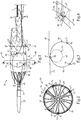
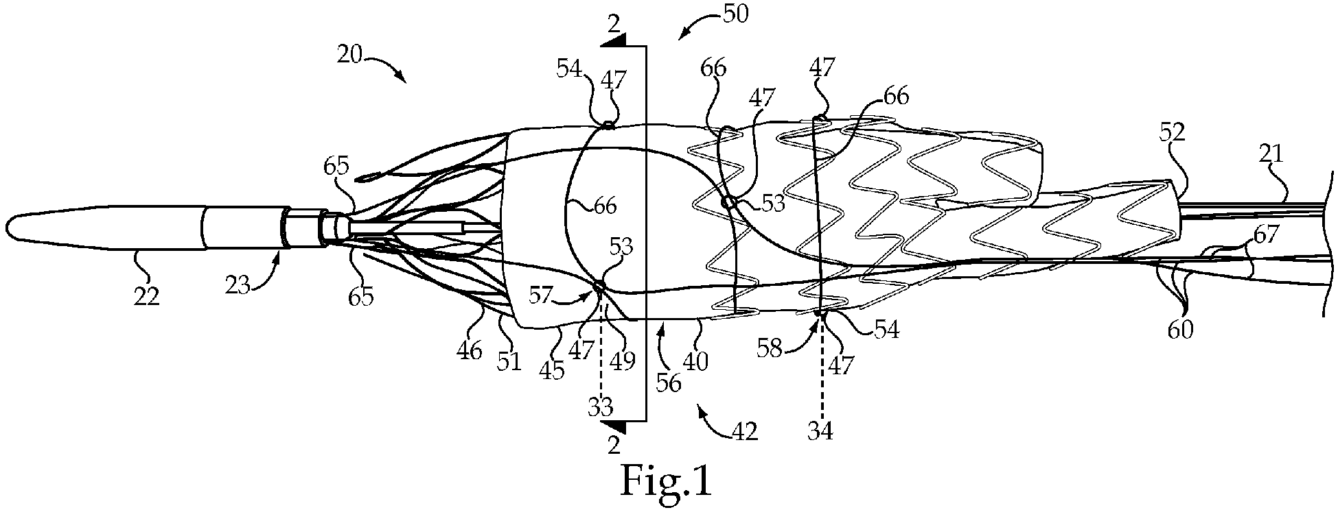
Fig. 1 is an enlarged side view of an embodiment of stent graft and control tether assembly mounted on the delivery system, which is partially shown; -
Fig. 2 is a sectioned view through the assembly ofFig. 1 as viewed along section lines 2-2; -
Fig. 3 is a schematic view of the control tether being tensioned between reduced and enlarged diameter configurations; -
Fig. 4 is a close up perspective view through one of the loops ofFig. 1 ; -
Fig. 5 is an enlarged schematic sectioned view of the tip of a delivery catheter for the delivery system ofFig. 1 ; -
Fig. 6 is an enlarged see-through perspective view of the tip region of the delivery system ofFig. 1 ; -
Fig. 7 is a partial sectioned view through the tether clamp ofFig. 5 in a clamped position; -
Fig. 8 is a partial sectioned view of through the tether clamp in a release position; -
Fig. 9 is a schematic view of a handle for the delivery system ofFig. 1 ; -
Fig. 10 is a schematic section view through the axial movement actuator and a portion of the handle along section lines 10-10 ofFig. 9 ; -
Fig. 11 is a schematic section view similar toFig. 10 except showing the axial movement actuator unlocked for movement; -
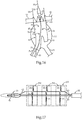
Fig. 12 is a schematic view of a controlled expansion stent graft delivery system being maneuvered through an aorta in a delivery configuration; -
Fig. 13 shows the delivery system moved from the delivery configuration ofFigure 10 to an adjustment configuration; -
Fig. 14 is a schematic view of the delivery system in the adjustment configuration with the stent graft expanded; -
Fig. 15 is a schematic view of the delivery system an adjustment configuration with the stent graft partially expanded; -
Fig. 16 is a schematic view of the delivery system ofFig. 10 in a detached configuration; and -
Fig. 17 is a schematic view of two more version of delivery system according to the present disclosure. - Referring initially to
Figs. 1-11 , a controlled expansion stentgraft delivery system 20 is utilized to deliver astent graft 40 to a treatment location in a patient. In the illustrated embodiment,stent graft 40 includes afabric tube 45 that is attached to, and supported by, aself expanding stent 46, and is shaped for treatment of an abdominal aortic aneurism in a manner known in the art.Stent graft 40 is a portion of anassembly 50 that includes at least onecontrol tether 60. Apart from a stent graft andcontrol tether assembly 50, thedelivery system 20 includes adelivery catheter 21 with atip 22 that includes atether clamp 23. Aretractable sheath 30 is slidably movable with regard to thedelivery catheter 21 in a manner well known in the art. In addition to the sutures that may or may not be included to attach thefabric tube 45 to theself expanding stent 46, thestent graft 40 includes a plurality ofloops 47 that are attached to at least one of thefabric tube 45 and theself expanding stent 46.Loops 47 may be formed with suture material. Each of theloops 47 has anopening 48 exposed on a radiallyoutward side 49 offabric tube 45. Each of three control tether(s) 60 in the illustrated embodiment includes afirst segment 65, amiddle segment 66 and asecond segment 67. Eachmiddle segment 66 is wrapped around thefabric tube 45 and is received through therespective openings 48 of theloops 47 at each of three different longitudinal positions alongstent graft 40. Thefirst segment 65 of each of thecontrol tethers 60 extends beyond one end 51 of thefabric tube 45. Each of thesecond segments 67, which are longer than the respectivefirst segments 65, extends beyond anopposite end 52 of thefabric tube 45. - As partially shown in
Fig. 5 ,delivery system 20 has adelivery configuration 35 in which thestent graft 40 is mounted on thedelivery catheter 21 in a compressedstate 41 and covered by theretractable sheath 30, which is at acovering position 31. Thedelivery system 20 is movable from thedelivery configuration 35 shown inFig. 5 to an adjustment configuration 36 (Figs. 13-15 ) in which tension in the control tether(s) 60 keeps thestent graft 40 from fully expanding to allow the user to adjust a position and/or an orientation of thestent graft 40 in-vitro. Thedelivery system 20 may be moved from theadjustment configuration 36 to a release configuration 37 (Fig. 8 ) with the stent graft in an expandedstate 42 after the positioning and orientation of thestent graft 40 have been adjusted by the user to a desired landing zone in the treatment vessel. The release configuration is characterized by thecontrol tether 60 being released fromtether clamp 23 but still wrapped aroundstent graft 40. Thereafter, thedelivery system 20 may be movable from therelease configuration 37 to adetached configuration 30 in which thestent graft 40 is in the expandedstate 42 and the control tether(s) 60 is pulled towardhandle 26 and out of contact with thestent graft 40. Thus, the use of the control tether(s) 60 allows the user to controllably expand, shrink and re-expand thestent graft 40 in-vitro to better position thestent graft 40 at a desired position and orientation within a patient. - In the example embodiment shown in
Figs. 1 and 2 ,stent graft 40 includes afirst set 57 of threeloops 47 located at a first longitudinal location 33, and asecond set 58 of at least threeloops 47 at a secondlongitudinal location 34 that is spaced along the longitudinal axis from the first set ofloops 57. In addition, a third set of at least threeloops 47 is located at a longitudinal position between the first longitudinal location 33 and the secondlongitudinal location 34. Although each longitudinal location has threeloops 47, one, two or four or more loops at each location would also fall within the scope of this disclosure. These spaced apart longitudinal positions are chosen such that when the tension is applied to the control tethers 60, the respectivemiddle segments 66 can be used to change theself expanding stent 46 between a reduced diameter configuration 55 (Fig. 3 ) when the control tether(s) 60 is in tension, and an enlarged diameter configuration 56 (Figs. 1-3 ) when the control tether(s) 60 has little or no tension. As best shown inFig. 4 , theopening 48 defined by each of theloops 47 is at least several times larger than thediameter 68 of therespective control tether 60 so that thecontrol tether 60 is freely slidable through therespective opening 48. In the illustrated embodiment, theloops 47 have been shown added to a conventional AAA bifurcated main body graft of the type manufactured by Cook Inc., but the present disclosure is also applicable to stent grafts for virtually any treatment application, especially those requiring precise placement and orientation. Each of the respective control tethers 60 is received through one of theloops 53 in the respective set ofloops other loops 54 of that respective set of loops exactly once. This feature is shown for example inFig. 2 , and partially shown inFigs. 1, 3 and 4 . - When
delivery system 20 is in either the delivery configuration 35 (Fig. 12 ) and an adjustment configuration 36 (Figs. 13-15 ) to be described infra, thefirst segment 65 of each of the respective control tethers 60 is held by thetether clamp 23, which forms a portion oftip 22. Thus, by jailingfirst segments 65, a user can apply tension to the remote end ofsecond segment 67 by moving anaxial movement actuator 28 mounted to move on thehandle 26, to control shrinkage and expansion of thestent graft 40 between the reduceddiameter configuration 55 and theenlarged diameter configuration 56. Thestent graft 40 changes its diameter responsive to a tension level in the control tether(s) 60 when thedelivery system 20 is in itsadjustment configuration 36. The user may actually reduce the diameter ofstent graft 40 responsive to an increase in the tension level of the control tether(s) 60 when thedelivery system 20 is in theadjustment configuration 36. The tension level in thecontrol tether 60 acts in opposition to the spring tendency of theself expanding stent 46 to expand. - Referring now specifically to
Figs. 9-11 , thedelivery system 20 includes ahandle 26 attached todelivery catheter 21 at anend 27 opposite to thetip 22. The remote end of control tether(s) 60 is attached to anaxial movement actuator 28 mounted to handle 26. Theaxial movement actuator 28 is constrained to move within a guidingslot 87 that include guide surfaces defined by portions ofhandle 26.Guide slot 87 may be aligned with the longitudinal axis ofcatheter 21. In the illustrated embodiment, theaxial movement actuator 28 can be stopped in perpendicularly orientednotches axial position actuator 28 in thenotch 84 corresponding to afirst position 81 such that the control tether(s) 60 would not interfere with full radial expansion of thestent graft 40 at time of implantation. However, if thestent graft 40 lands at an undesirable location or orientation, the user may then move theaxial movement actuator 28 towardnotches 85 or 86 (adjustment configuration 36) in order to apply tension to control tether(s) 60 to reduce the diameter of thestent graft 40 to make it possible to readjust at least one of its position and orientation at the implantation site. Thereafter the user can again move theaxial position actuator 28 toward thefirst notch 84 in order to allow for full expansion of thestent graft 40 at the new landing location. Theaxial position actuator 28 may include aposition lock 90 so that the axial position actuator can be locked into one of the notches 84-86, or maybe even at a desired intermediate location inguide slot 87. This may be accomplished by a threadedend 91 of theaxial position actuator 28 being threadably received in ablock 92, with a wall of thehandle 26 sandwiched therebetween. By tighteningthreads 91 intoblock 92, the wall of thehandle 26 can be clamped therebetween to hold thecontrol tether 60 in a desired placement and tension state, corresponding to theposition lock 90 being in a locked state. By untighteningthreads 91 fromblock 92 the position lock is placed in a unlocked state, and theaxial position actuator 28 may be moved to any desired location constrained byguide slot 87, and then may be stopped at that new location by again lockingposition lock 90. The remote end ofcontrol tether 60 may be attached to move withblock 92 as shown inFigs. 10 and 11 . -
Position lock 90 could take on other forms and structures known in the art for allowing and locking against relative movement in medical devices. AlthoughFig. 9 shows theaxial position actuator 28 initially positioned at a first position innotch 84, the system could also be set up initially to have the axial position actuator in an optionalinitial position 83 corresponding to notch 86. In such a case, thecontrol tether 60 would initially be in tension to prevent thestent graft 40 from fully expanding after theretractable sheath 30 is moved to its retractedposition 32. In such an instance, the operator could then manipulate the delivery system and the control tether via theaxial movement actuator 28 to controllably land thestent graft 40 at a desired location and orientation at a delivery site. Thus, thedelivery system 20 of the present disclosure can be set up initially to allow the operator to only use the control tethers if thestent graft 40 lands at an undesirable location or orientation, or may allow the user to control the expansion of thestent graft 40 prior to any landing. - A remote end of the
clamp release line 77 may be attached to aclamp release lock 95 such that theclamp release line 77 extends between the tether clamp 23 (Fig. 5 ) and the handle 26 (Fig. 9 ). In the illustrated embodiment,clamp release lock 95 operates by including a threadedend 96 received in a threaded bore 97 defined byhandle 26. Thus, when theclamp release lock 95 is threadably received in threaded bore 97 as shown inFig. 9 , theclamp release actuator 98 is inoperable.Fig. 9 also shows the dotted lines after theclamp release actuator 95 has been unthreaded from threaded bore 97 and moved backwards to move thetether clamp 23 from its clampedposition 78 to therelease position 79.Numerals Figs. 7-9 to show the relationship betweenclamp release actuator 98 and the positioning oftether clamp 23. Movement of the tether clamp may be enabled by unthreadingclamp release actuator 98 from threaded bore 97 inhandle 26 to allow the clamp release actuator to be moved away fromhandle 26 to move the tether clamp to itsrelease position 79. When atether clamp 23 is in therelease configuration 79, theaxial movement actuator 28 may be moved in the direction ofnotch 86 to move the remote end ofcontrol tether 60 away fromtether clamp 23. - Other clamp release lock structures would also fall within the intended scope of this disclosure. Although the illustrated embodiment shows the
tether clamp 23 being moved to arelease position 79 by pulling on aclamp release line 77, the present disclosure also contemplates other release lock arrangements. For instance, a cannula may be mounted aboutdelivery catheter 21 and operable slid to a compression position in contact withtether clamp 23 to cause the same to release. In such an embodiment, the remote end of the cannulaadjacent handle 26 might include a clamping feature to require that the cannula be unclamped fromcatheter 21 before the clamp release function is made operable by movement of the cannula. - Although
tether clamp 23 can take on a wide variety of different forms, in the illustrated embodiment as best shown inFigs. 5-8 , the illustratedtether clamp 23 includes amale part 24 that is mated to afemale part 25. In the illustrated embodiment,tether clamp 23 includes atension spring 76 that is operably positioned to bias themale part 24 and thefemale part 25 toward a clampedposition 78 as shown inFig. 7 . Those skilled in the art will appreciate that the spring could be a compression spring with an appropriate rearrangement of the male and female portions of the tether claim without departing from the present disclosure. Aclamp release line 77 may be connected totether clamp 23 in general, and in the illustrated embodiment to themale part 24 in particular. Thetether clamp 23 can move from the clamped position as shown inFig. 7 toward arelease position 79 as shown inFig. 8 responsive to tension in theclamp release line 77 overcoming the bias ofspring 76. Thus, after thestent graft 40 is precisely placed, thetether clamp 23 can be moved to itsrelease position 79 to allow the control tether(s) 60 to be withdrawn toward ahandle 26 ofdelivery system 20 and out of contact withstent graft 40. In the illustrated embodiment, the threecontrol tethers 60 are shown as merged into asingle control tether 60 before attachment toaxial movement actuator 28 so that the threecontrol tethers 60 shown inFig. 1 can be simultaneously tensioned and un-tensioned responsive to movement ofaxial movement actuator 28 and the remote end of thecontrol tether 60 relative to handle 26 as shown inFig. 9 . The user may increase or decrease tension in the control tether(s) 60 and allow theself expanding stent 46 to pull thecontrol tether 60 towardstent graft 40, or in a reverse direction to increase tension against the action of theself expanding stent 46. - Although not necessary, each
control tether 60 may be amonofilament wire 63, with thetether clamp 23 constructed to contact themonofilament wire 63 at three spaced apartlocations 73 around acircumference 64 of themonofilament wire 63 as best shown inFigs. 7 . In order to have the three point clamping configuration as shown inFig. 7 , one of themale part 24 and thefemale part 23 defines a v-shapedgroove 70 that includes two of three clampingsurfaces 71 that contact themonofilament wire 63 at two of three spaced apartlocations 73. The other one of themale part 24 andfemale part 25 includes a clampingsurface 74 that contacts themonofilament wire 63 at a remaining one 75 of the three spaced apartlocations 73. Those skilled in the art will appreciate that other clamping configurations could be utilized, and the control tether(s) could be multifilament instead of themonofilament wire 63 of the illustrated embodiment. - Referring now in addition to
Fig. 17 , a couple of different variations of a stent graft and controltether assembly assembly 150, a single stent graft is schematically shown and has asingle control tether 60 wrapped around the stent graft so thatmiddle segment 66 wraps around the fabric tube a first time and asecond time 69 and the third time, thus illustrating that each control tether may wrap around an individual stent graft more than one time at different longitudinal locations along the stent graft. Also shown, is anassembly 250 in which three separate stent grafts share a commonsingle control tether 60 such that each of the three stent grafts has amiddle segment 66 of thecontrol tether 60 wrapped one time around each of the three stent grafts. Thus, those skilled in the art will appreciate that the present disclosure is applicable to delivery assemblies for delivering more than one stent graft that share a common control tether and to a single stent graft that uses only one control tether wrapped around the stent graft more than one time. This is to be contrasted with the illustrated embodiment in which threecontrol tethers 60 are used with each of the control tethers 60 being wrapped around thestent graft 40 one time. Those skilled in the art will appreciate that other permutations would also fall within the scope of this disclosure. - Referring now in addition to
Figs. 12-16 , an example method of operating a controlled expansion stentgraft delivery system 20 is shown for treating ananeurysm 12 in theaorta 10 that is located immediately below branching vessels, which may include therenal artery 11. Thedelivery system 20 may approach the implantation site utilizing a previously placedwire guide 80 utilizing an access in the patient's leg (not shown) and travel up through theiliac artery 15.Wire guide 80 may be received through alumen 29 ofdelivery catheter 21. In particular, thedelivery system 20 is positioned at a treatment site in adelivery configuration 35 in which thestent graft 40 is mounted ondelivery catheter 21 in acompressed state 41 and covered byretractable sheath 30, which is at acovering position 31. Next, as shown inFig. 13 , the delivery system is moved to theadjustment configuration 36 with theretractable sheath 30 moved from the coveringposition 31 shown inFig. 10 to the retractedposition 32 to uncover thestent graft 40. Because thestent graft 40 did not fully expand upon retraction ofretractable sheath 30, this reveals that the control tether(s) 60 were configured with some initial tension by initially positioningaxial position actuator 28 innotch 86 or innotch 85 depending upon the total movement length available forcontrol tether 60 in a given diametrical application. When in theadjustment configuration 36, the control tethers 60 have sufficient tension to prevent thestent graft 40 from fully expanding. When in this configuration, theretractable sheath 30 is out of contact with thestent graft 40. However, the control tethers 60 are held by thetether clamp 23, are wrapped around thestent graft 40, and received through theopenings 48 in theindividual loops 47 of thestent graft 40. Thedelivery system 20 may be changed from the delivery configuration ofFig. 12 to theadjustment configuration 36, thus allowing the user to make some orientation change viarotating delivery system 20 about its longitudinal axis and positioning adjustments by advancing or retracting thedelivery system 20 with regard to theaneurysm 12. When the user believes that thestent graft 40 is properly positioned, tension on the control tethers 60 may be relaxed by unlockingposition lock 90 and moving axial position actuator towardnotch 84, and allow the self-expandingstent 46 to move thestent graft 40 into contact with the vessel wall at aninitial landing zone 16. The user can then use known visualization strategies to assess both the orientation and placement ofstent graft 40 while thedelivery system 20 is still in anadjustment configuration 36. The difference between theadjustment configuration 36 shown inFig. 13 and that shown inFig. 14 is associated with the level of tension in the control tether(s) 60 via the positioning ofaxial movement actuator 29. If the physician deems that theinitial landing zone 16 is not acceptable, the tension level in the control tethers 60 may be increased to shrink the diameter ofstent graft 40 as shown inFig. 15 . When in theadjustment configuration 36, the user may adjust the orientation and position of thestent graft 40, and then relieve tension on the control tether(s) 60 so that thestent graft 40 is controllably expanded to the desiredlanding zone 13 as shown inFig. 16 . After confirming the proper placement ofstent graft 40, the physician may release the top stent proximal fixation that are adjacent therenal artery 11 in a manner well known in the art. Next, after confirming a proper seal, thedelivery system 20 may be moved from theadjustment configuration 36 to a release configuration 37 (Fig. 8 ) in which thecontrol tether 60 is released from thetether clamp 23, but remains wrapped around thestent graft 40 and received through theopenings 48 of theloops 47, and thestent graft 40 is in its expandedstate 42. Changing to the release configuration may include movement of theclamp release lock 95 to an un-locked state by unthreadingclamp release actuator 98 from threaded bore 97. Next, the clamp release actuator is moved away fromhandle 26 as shown inFig. 9 to movetether clamp 23 to itsrelease position 79. When this is done, theaxial movement actuator 28 may be moved slightly to move the remote end ofcontrol tether 60 out oftether clamp 23 so that when thetether clamp 23 returns toward its clamp position under the action ofspring 76, thecontrol tether 60 is no longer present. This movement moves theclamp release line 77 to move theclamp 23 from theclamp position 78 shown inFig. 7 to the unclamped positioned 79 shown inFig. 8 . - Thereafter, the
delivery system 20 may then be moved from therelease configuration 37 to adetached configuration 38 as shown inFig. 16 in which thestent graft 40 is at the expandedstate 42 and thecontrol tether 60 is slid out of contact with thestent graft 40. This is accomplished because thefirst segment 65 of the individual control tether(s) have been released fromtether clamp 23, and withdrawn back throughloops 47 towardhandle 26 and out of contact with thestent graft 40. Next, the user may withdraw thedelivery system 20 leaving thestent graft 40 implanted in a desired position and orientation. - Those skilled in the art will appreciate that while the
delivery system 20 is in theadjustment configuration 36 as shown inFigs. 13-15 , the expansion ofstent graft 40 may be stopped by increasing tension in the control tether(s) 60. The user may then adjust at least one of the orientation and position of thestent graft 40 while expansion of thestent graft 40 has been stopped. Thereafter, the expansion of the stent graft may be controllably resumed by decreasing tension incontrol tether 60. The expansion of thestent graft 40 may be stopped by securing theaxial movement actuator 28 at any desired position usingposition lock 90. If the positioning and/or orientation are not as desired, thestent graft 40 may be contracted toward thecompressed state 41 by increasing tension in thecontrol tether 60 while thedelivery system 20 is in theadjustment configuration 36. As discussed earlier, after proper placement, thetether clamp 23 may be moved from its clampedposition 78 to itsrelease position 79 responsive to increasing tension in the clampedrelease line 77. - The present disclosure finds general applicability to any self-expanding stent graft. The present disclosure finds particular applicability to stent grafts with sensitivities to placement location and/or orientation, such as for accommodating branch vessels. The present disclosure finds specific applicability for delivering stent grafts to high flow areas, such as those associated with the aorta, which also include many branching arteries that must be accommodated by proper placement and orientation of a stent graft.
- It should be understood that the above description is intended for illustrative purposes only, and is not intended to limit the scope of the present disclosure in any way. Thus, those skilled in the art will appreciate that other aspects of the disclosure can be obtained from a study of the drawings, the disclosure and the appended claims.
- The disclosures in United States patent application number
62/446,688
Claims (15)
- A controlled expansion stent graft delivery system including:a delivery catheter with a tip that includes a tether clamp, and has a longitudinal axis;a retractable sheath;a stent graft that includes a fabric tube attached to, and supported by, a self-expanding stent;a handle attached to the delivery catheter at an end opposite to the tip;a control tether attached to an axial movement actuator mounted to the handle;the delivery system having a delivery configuration in which the stent graft is mounted on the delivery catheter in a compressed state and covered by the retractable sheath;the delivery system having an adjustment configuration in which the retractable sheath is at retracted position out of contact with the stent graft; and the control tether is held by the tether clamp, wrapped around the stent graft, and the axial movement actuator is at a second position with respect to the handle;the delivery system having a release configuration in which the control tether is released from the tether clamp, wrapped around the stent graft, and the stent graft is in an expanded state;the delivery system having a detached configuration in which the stent graft is in the expanded state and the control tether is out of contact with the stent graft; andthe axial movement actuator is at a first position with respect to the handle in at least one of the delivery configuration and the release configuration.
- A delivery system according to claim 1, wherein the axial movement actuator is at the first position with respect to the handle when the delivery system is in the release configuration; and
the expansion state of the stent graft being greater when the axial movement actuator is in the first position versus the second position. - A delivery system according to claim 1 or 2, wherein the axial movement actuator is at a first position with respect to the handle when the delivery system is in the delivery configuration;
the expansion state of the stent graft being greater when the axial movement actuator is in the second position versus the first position. - A delivery system according to any preceding claim, including a position lock moveable between an unlocked state at which the axial movement actuator can move away from one of the first position and the second position, and a locked state at which the axial movement actuator is locked at the one of the first position and the second position.
- A delivery system according to any preceding claim, including a clamp release line extending between the tether clamp and the handle, and being moveable between a clamp position at which the tether is held by the tether clamp, and a release position at which control tether is released from the tether clamp.
- A delivery system according to any preceding claim, wherein the tether clamp includes a spring operably positioned to bias the tether clamp toward a clamp position.
- A delivery system according to any preceding claim, including a clamp release lock positioned closer to the handle than to the tip, and being moveable between a first position at which a clamp release actuator is inoperable, and a second position at which the clamp release actuator is operable to move the tether clamp from a clamp position toward a release position.
- A delivery system according to any preceding claim, wherein the tether clamp includes a spring operably positioned to bias the tether clamp toward the clamp position; and
a clamp release line extending between the tether clamp and the handle, and being moveable between the clamp position at which the tether is held by the tether clamp, and the release position at which tether is released from the tether clamp. - A delivery system according to any preceding claim, wherein the handle includes a longitudinal guide surface oriented parallel to the longitudinal axis; and
the guide surface constrains the axial movement actuator between the first position and the second position. - A delivery system according to any preceding claim, including a position lock moveable between an unlocked state at which the axial movement actuator can move away from the second position, and a locked state at which the axial movement actuator is locked at the second position.
- A delivery system according to any preceding claim, wherein the axial movement actuator is at the first position with respect to the handle when the delivery system is in the release configuration; and
the expansion state of the stent graft being greater when the axial movement actuator is in the first position versus the second position. - A delivery system according to any preceding claim, wherein the axial movement actuator is at a first position with respect to the handle when the delivery system is in the delivery configuration;
the expansion state of the stent graft being greater when the axial movement actuator is in the second position versus the first position. - A delivery system according to any preceding claim, wherein expansion of the stent graft can be stopped by positioning the axial adjustment actuator at the second position while the delivery system is in the adjustment configuration;
at least one of an orientation and a position of the stent graft can be adjusted while the expansion of the stent graft is stopped; and
expansion of the stent graft can be resumed by decreasing tension in the control tether by moving the axial adjustment actuator away from the second position. - A delivery system according to any preceding claim, wherein the stent graft can be partially expanded by moving the axial movement actuator from the first position to the second position when changing from the delivery configuration to the adjustment configuration.
- A delivery system according to any preceding claim, wherein the stent graft can be contracted toward the compressed state by moving the axial adjustment actuator.
Applications Claiming Priority (1)
| Application Number | Priority Date | Filing Date | Title |
|---|---|---|---|
| US201762446688P | 2017-01-16 | 2017-01-16 |
Publications (2)
| Publication Number | Publication Date |
|---|---|
| EP3348233A1 true EP3348233A1 (en) | 2018-07-18 |
| EP3348233B1 EP3348233B1 (en) | 2019-08-21 |
Family
ID=60915239
Family Applications (1)
| Application Number | Title | Priority Date | Filing Date |
|---|---|---|---|
| EP17208215.8A Active EP3348233B1 (en) | 2017-01-16 | 2017-12-18 | Controlled expansion stent graft delivery system |
Country Status (2)
| Country | Link |
|---|---|
| US (1) | US10463517B2 (en) |
| EP (1) | EP3348233B1 (en) |
Cited By (1)
| Publication number | Priority date | Publication date | Assignee | Title |
|---|---|---|---|---|
| CN109700566A (en) * | 2018-12-27 | 2019-05-03 | 东莞先健畅通医疗有限公司 | Conveying device and system |
Families Citing this family (21)
| Publication number | Priority date | Publication date | Assignee | Title |
|---|---|---|---|---|
| US8579964B2 (en) | 2010-05-05 | 2013-11-12 | Neovasc Inc. | Transcatheter mitral valve prosthesis |
| US9308087B2 (en) | 2011-04-28 | 2016-04-12 | Neovasc Tiara Inc. | Sequentially deployed transcatheter mitral valve prosthesis |
| US9554897B2 (en) | 2011-04-28 | 2017-01-31 | Neovasc Tiara Inc. | Methods and apparatus for engaging a valve prosthesis with tissue |
| US9345573B2 (en) | 2012-05-30 | 2016-05-24 | Neovasc Tiara Inc. | Methods and apparatus for loading a prosthesis onto a delivery system |
| US9572665B2 (en) | 2013-04-04 | 2017-02-21 | Neovasc Tiara Inc. | Methods and apparatus for delivering a prosthetic valve to a beating heart |
| JP7002451B2 (en) | 2015-12-15 | 2022-01-20 | ニオバスク ティアラ インコーポレイテッド | Transseptal delivery system |
| CN108882981B (en) | 2016-01-29 | 2021-08-10 | 内奥瓦斯克迪亚拉公司 | Prosthetic valve for preventing outflow obstruction |
| AU2017361296B2 (en) | 2016-11-21 | 2022-09-29 | Neovasc Inc. | Methods and systems for rapid retraction of a transcatheter heart valve delivery system |
| EP3672530A4 (en) | 2017-08-25 | 2021-04-14 | Neovasc Tiara Inc. | SEQUENTIAL DEPLOYMENT TRANSCATHETER MITRAL VALVE PROSTHESIS |
| AU2019374743B2 (en) | 2018-11-08 | 2022-03-03 | Neovasc Inc. | Ventricular deployment of a transcatheter mitral valve prosthesis |
| CN113747863B (en) | 2019-03-08 | 2024-11-08 | 内奥瓦斯克迪亚拉公司 | Retrievable Prosthesis Delivery System |
| JP7609796B2 (en) | 2019-03-20 | 2025-01-07 | インキュベート メディカル テクノロジーズ、 エルエルシー | Aortic Dissection Implant |
| AU2020256195B2 (en) | 2019-04-01 | 2022-10-13 | Neovasc Inc. | Controllably deployable prosthetic valve |
| US11491006B2 (en) | 2019-04-10 | 2022-11-08 | Neovasc Tiara Inc. | Prosthetic valve with natural blood flow |
| CA3282225A1 (en) | 2019-05-20 | 2026-03-02 | Neovasc Tiara Inc. | Introducer with hemostasis mechanism |
| JP7520897B2 (en) | 2019-06-20 | 2024-07-23 | ニオバスク ティアラ インコーポレイテッド | Thin prosthetic mitral valve |
| US11554034B2 (en) | 2020-10-06 | 2023-01-17 | Venus Medtech (Hangzhou) Inc. | Method and assembly for securing an implantable medical device on a delivery system |
| CN117042828A (en) * | 2021-02-10 | 2023-11-10 | 开普斯坦医疗股份有限公司 | Systems, devices and methods for conveyor systems |
| CN113208776B (en) * | 2021-04-25 | 2025-07-08 | 浙江大学 | Prosthetic heart valve and delivery device |
| CN115770131A (en) * | 2021-09-07 | 2023-03-10 | 上海蓝脉医疗科技有限公司 | Conveyor system |
| CN116327447B (en) * | 2023-05-24 | 2023-08-18 | 杭州启明医疗器械股份有限公司 | Intervention system with interception |
Citations (3)
| Publication number | Priority date | Publication date | Assignee | Title |
|---|---|---|---|---|
| EP2471498A1 (en) * | 2010-12-31 | 2012-07-04 | Cook Medical Technologies LLC | Conformable prosthesis delivery system and method for deployment thereof |
| EP2832322A1 (en) * | 2013-07-30 | 2015-02-04 | Nvt Ag | Deployment system for a cardiac valve prosthesis |
| EP3272319A1 (en) * | 2016-07-18 | 2018-01-24 | Cook Medical Technologies LLC | Controlled expansion stent graft delivery system |
Family Cites Families (21)
| Publication number | Priority date | Publication date | Assignee | Title |
|---|---|---|---|---|
| US5776142A (en) | 1996-12-19 | 1998-07-07 | Medtronic, Inc. | Controllable stent delivery system and method |
| US6168616B1 (en) * | 1997-06-02 | 2001-01-02 | Global Vascular Concepts | Manually expandable stent |
| US20030050684A1 (en) | 2001-09-10 | 2003-03-13 | Abrams Robert M. | Internal restraint for delivery of self-expanding stents |
| US7763063B2 (en) * | 2003-09-03 | 2010-07-27 | Bolton Medical, Inc. | Self-aligning stent graft delivery system, kit, and method |
| US8500792B2 (en) * | 2003-09-03 | 2013-08-06 | Bolton Medical, Inc. | Dual capture device for stent graft delivery system and method for capturing a stent graft |
| US9198786B2 (en) * | 2003-09-03 | 2015-12-01 | Bolton Medical, Inc. | Lumen repair device with capture structure |
| JP4850712B2 (en) * | 2003-10-10 | 2012-01-11 | ウィリアム・クック・ヨーロッパ・アンパルトセルスカブ | Stent graft retention system |
| US7468070B2 (en) * | 2004-01-23 | 2008-12-23 | Boston Scientific Scimed, Inc. | Stent delivery catheter |
| CA2642250A1 (en) | 2006-02-13 | 2007-08-23 | Merlin Md Pte Ltd | Endovascular device with membrane |
| EP2366363B1 (en) | 2006-04-27 | 2015-01-14 | Cook Medical Technologies LLC | Deploying Medical Implants |
| US8834550B2 (en) * | 2006-05-19 | 2014-09-16 | Boston Scientific Scimed, Inc. | Apparatus and method for loading and delivering a stent using a suture retaining mechanism |
| EP2146669B1 (en) | 2007-05-11 | 2014-07-30 | Cook Medical Technologies LLC | Stent grafts for the thoracic aorta |
| US20110022149A1 (en) | 2007-06-04 | 2011-01-27 | Cox Brian J | Methods and devices for treatment of vascular defects |
| JP5591120B2 (en) * | 2008-01-16 | 2014-09-17 | セント ジュード メディカル インコーポレイテッド | Collapsible / expandable prosthetic heart valve delivery and retrieval system |
| US9149358B2 (en) * | 2008-01-24 | 2015-10-06 | Medtronic, Inc. | Delivery systems for prosthetic heart valves |
| EP2254529A2 (en) | 2008-02-19 | 2010-12-01 | William Cook Europe APS | Coated endoluminal implant |
| GB2474252B (en) * | 2009-10-07 | 2012-01-25 | Cook Medical Technologies Llc | Deployment handle for an introducer |
| US8663305B2 (en) | 2010-04-20 | 2014-03-04 | Medtronic Vascular, Inc. | Retraction mechanism and method for graft cover retraction |
| JP6326648B2 (en) | 2012-08-10 | 2018-05-23 | アルツラ メディカル インコーポレイテッド | Stent delivery system and related method |
| US10709541B2 (en) * | 2017-04-28 | 2020-07-14 | Cook Medical Technologies Llc | Systems and methods for adjusting the diameter of an endoluminal prosthesis and an endoluminal prosthesis configured for the same |
| CN209933067U (en) * | 2018-01-07 | 2020-01-14 | 苏州杰成医疗科技有限公司 | Prosthetic heart valve delivery system |
-
2017
- 2017-11-27 US US15/822,760 patent/US10463517B2/en active Active
- 2017-12-18 EP EP17208215.8A patent/EP3348233B1/en active Active
Patent Citations (3)
| Publication number | Priority date | Publication date | Assignee | Title |
|---|---|---|---|---|
| EP2471498A1 (en) * | 2010-12-31 | 2012-07-04 | Cook Medical Technologies LLC | Conformable prosthesis delivery system and method for deployment thereof |
| EP2832322A1 (en) * | 2013-07-30 | 2015-02-04 | Nvt Ag | Deployment system for a cardiac valve prosthesis |
| EP3272319A1 (en) * | 2016-07-18 | 2018-01-24 | Cook Medical Technologies LLC | Controlled expansion stent graft delivery system |
Cited By (2)
| Publication number | Priority date | Publication date | Assignee | Title |
|---|---|---|---|---|
| CN109700566A (en) * | 2018-12-27 | 2019-05-03 | 东莞先健畅通医疗有限公司 | Conveying device and system |
| CN109700566B (en) * | 2018-12-27 | 2021-09-21 | 深圳市先健畅通医疗有限公司 | Conveying device and system |
Also Published As
| Publication number | Publication date |
|---|---|
| EP3348233B1 (en) | 2019-08-21 |
| US10463517B2 (en) | 2019-11-05 |
| US20180200093A1 (en) | 2018-07-19 |
Similar Documents
| Publication | Publication Date | Title |
|---|---|---|
| EP3348233B1 (en) | Controlled expansion stent graft delivery system | |
| EP3272319B1 (en) | Controlled expansion stent graft delivery system | |
| US11096811B2 (en) | Deployment handle for an introducer | |
| EP2359776B1 (en) | Prosthesis Deployment System | |
| US11123208B2 (en) | Prosthesis delivery system with tip travel limiter and method of use | |
| US10292847B2 (en) | System and method for the sequential expansion of a medical device | |
| EP2262444B1 (en) | Stent-graft | |
| US7998189B2 (en) | Curvable stent-graft and apparatus and fitting method | |
| CN105050549B (en) | Stent delivery system and associated method | |
| US20140236278A1 (en) | Stent-Graft Delivery Having a Tip Capture Mechanism With Elongated Cables for Gradual Deployment and Repositioning | |
| US20130345789A1 (en) | Systems and methods for deploying a portion of a stent using at least one coiled member | |
| US20100274187A1 (en) | Centering for a TAA | |
| EP2529705B1 (en) | Introducer for deploying an implant | |
| US20190374359A1 (en) | Tip clamp assembly and controlled expansion stent graft delivery system using same | |
| US9351860B2 (en) | Loading tool for capturing stent points | |
| AU2009234483B2 (en) | Stent-graft and apparatus and fitting method | |
| AU2012211486A1 (en) | Trigger wire release mechanism |
Legal Events
| Date | Code | Title | Description |
|---|---|---|---|
| PUAI | Public reference made under article 153(3) epc to a published international application that has entered the european phase |
Free format text: ORIGINAL CODE: 0009012 |
|
| STAA | Information on the status of an ep patent application or granted ep patent |
Free format text: STATUS: THE APPLICATION HAS BEEN PUBLISHED |
|
| AK | Designated contracting states |
Kind code of ref document: A1 Designated state(s): AL AT BE BG CH CY CZ DE DK EE ES FI FR GB GR HR HU IE IS IT LI LT LU LV MC MK MT NL NO PL PT RO RS SE SI SK SM TR |
|
| AX | Request for extension of the european patent |
Extension state: BA ME |
|
| STAA | Information on the status of an ep patent application or granted ep patent |
Free format text: STATUS: REQUEST FOR EXAMINATION WAS MADE |
|
| 17P | Request for examination filed |
Effective date: 20180817 |
|
| RBV | Designated contracting states (corrected) |
Designated state(s): AL AT BE BG CH CY CZ DE DK EE ES FI FR GB GR HR HU IE IS IT LI LT LU LV MC MK MT NL NO PL PT RO RS SE SI SK SM TR |
|
| RIC1 | Information provided on ipc code assigned before grant |
Ipc: A61F 2/07 20130101AFI20190213BHEP Ipc: A61F 2/966 20130101ALI20190213BHEP Ipc: A61F 2/89 20130101ALI20190213BHEP Ipc: A61M 25/01 20060101ALI20190213BHEP Ipc: A61F 2/95 20130101ALI20190213BHEP Ipc: A61F 2/24 20060101ALI20190213BHEP |
|
| GRAP | Despatch of communication of intention to grant a patent |
Free format text: ORIGINAL CODE: EPIDOSNIGR1 |
|
| STAA | Information on the status of an ep patent application or granted ep patent |
Free format text: STATUS: GRANT OF PATENT IS INTENDED |
|
| INTG | Intention to grant announced |
Effective date: 20190408 |
|
| GRAS | Grant fee paid |
Free format text: ORIGINAL CODE: EPIDOSNIGR3 |
|
| GRAA | (expected) grant |
Free format text: ORIGINAL CODE: 0009210 |
|
| STAA | Information on the status of an ep patent application or granted ep patent |
Free format text: STATUS: THE PATENT HAS BEEN GRANTED |
|
| AK | Designated contracting states |
Kind code of ref document: B1 Designated state(s): AL AT BE BG CH CY CZ DE DK EE ES FI FR GB GR HR HU IE IS IT LI LT LU LV MC MK MT NL NO PL PT RO RS SE SI SK SM TR |
|
| REG | Reference to a national code |
Ref country code: GB Ref legal event code: FG4D |
|
| REG | Reference to a national code |
Ref country code: CH Ref legal event code: EP |
|
| REG | Reference to a national code |
Ref country code: DE Ref legal event code: R096 Ref document number: 602017006359 Country of ref document: DE |
|
| REG | Reference to a national code |
Ref country code: AT Ref legal event code: REF Ref document number: 1168830 Country of ref document: AT Kind code of ref document: T Effective date: 20190915 |
|
| REG | Reference to a national code |
Ref country code: IE Ref legal event code: FG4D |
|
| REG | Reference to a national code |
Ref country code: LT Ref legal event code: MG4D |
|
| REG | Reference to a national code |
Ref country code: NL Ref legal event code: MP Effective date: 20190821 |
|
| PG25 | Lapsed in a contracting state [announced via postgrant information from national office to epo] |
Ref country code: BG Free format text: LAPSE BECAUSE OF FAILURE TO SUBMIT A TRANSLATION OF THE DESCRIPTION OR TO PAY THE FEE WITHIN THE PRESCRIBED TIME-LIMIT Effective date: 20191121 Ref country code: SE Free format text: LAPSE BECAUSE OF FAILURE TO SUBMIT A TRANSLATION OF THE DESCRIPTION OR TO PAY THE FEE WITHIN THE PRESCRIBED TIME-LIMIT Effective date: 20190821 Ref country code: NL Free format text: LAPSE BECAUSE OF FAILURE TO SUBMIT A TRANSLATION OF THE DESCRIPTION OR TO PAY THE FEE WITHIN THE PRESCRIBED TIME-LIMIT Effective date: 20190821 Ref country code: HR Free format text: LAPSE BECAUSE OF FAILURE TO SUBMIT A TRANSLATION OF THE DESCRIPTION OR TO PAY THE FEE WITHIN THE PRESCRIBED TIME-LIMIT Effective date: 20190821 Ref country code: LT Free format text: LAPSE BECAUSE OF FAILURE TO SUBMIT A TRANSLATION OF THE DESCRIPTION OR TO PAY THE FEE WITHIN THE PRESCRIBED TIME-LIMIT Effective date: 20190821 Ref country code: PT Free format text: LAPSE BECAUSE OF FAILURE TO SUBMIT A TRANSLATION OF THE DESCRIPTION OR TO PAY THE FEE WITHIN THE PRESCRIBED TIME-LIMIT Effective date: 20191223 Ref country code: FI Free format text: LAPSE BECAUSE OF FAILURE TO SUBMIT A TRANSLATION OF THE DESCRIPTION OR TO PAY THE FEE WITHIN THE PRESCRIBED TIME-LIMIT Effective date: 20190821 Ref country code: NO Free format text: LAPSE BECAUSE OF FAILURE TO SUBMIT A TRANSLATION OF THE DESCRIPTION OR TO PAY THE FEE WITHIN THE PRESCRIBED TIME-LIMIT Effective date: 20191121 |
|
| PG25 | Lapsed in a contracting state [announced via postgrant information from national office to epo] |
Ref country code: ES Free format text: LAPSE BECAUSE OF FAILURE TO SUBMIT A TRANSLATION OF THE DESCRIPTION OR TO PAY THE FEE WITHIN THE PRESCRIBED TIME-LIMIT Effective date: 20190821 Ref country code: AL Free format text: LAPSE BECAUSE OF FAILURE TO SUBMIT A TRANSLATION OF THE DESCRIPTION OR TO PAY THE FEE WITHIN THE PRESCRIBED TIME-LIMIT Effective date: 20190821 Ref country code: GR Free format text: LAPSE BECAUSE OF FAILURE TO SUBMIT A TRANSLATION OF THE DESCRIPTION OR TO PAY THE FEE WITHIN THE PRESCRIBED TIME-LIMIT Effective date: 20191122 Ref country code: IS Free format text: LAPSE BECAUSE OF FAILURE TO SUBMIT A TRANSLATION OF THE DESCRIPTION OR TO PAY THE FEE WITHIN THE PRESCRIBED TIME-LIMIT Effective date: 20191221 Ref country code: RS Free format text: LAPSE BECAUSE OF FAILURE TO SUBMIT A TRANSLATION OF THE DESCRIPTION OR TO PAY THE FEE WITHIN THE PRESCRIBED TIME-LIMIT Effective date: 20190821 Ref country code: LV Free format text: LAPSE BECAUSE OF FAILURE TO SUBMIT A TRANSLATION OF THE DESCRIPTION OR TO PAY THE FEE WITHIN THE PRESCRIBED TIME-LIMIT Effective date: 20190821 |
|
| REG | Reference to a national code |
Ref country code: AT Ref legal event code: MK05 Ref document number: 1168830 Country of ref document: AT Kind code of ref document: T Effective date: 20190821 |
|
| PG25 | Lapsed in a contracting state [announced via postgrant information from national office to epo] |
Ref country code: TR Free format text: LAPSE BECAUSE OF FAILURE TO SUBMIT A TRANSLATION OF THE DESCRIPTION OR TO PAY THE FEE WITHIN THE PRESCRIBED TIME-LIMIT Effective date: 20190821 |
|
| PG25 | Lapsed in a contracting state [announced via postgrant information from national office to epo] |
Ref country code: RO Free format text: LAPSE BECAUSE OF FAILURE TO SUBMIT A TRANSLATION OF THE DESCRIPTION OR TO PAY THE FEE WITHIN THE PRESCRIBED TIME-LIMIT Effective date: 20190821 Ref country code: IT Free format text: LAPSE BECAUSE OF FAILURE TO SUBMIT A TRANSLATION OF THE DESCRIPTION OR TO PAY THE FEE WITHIN THE PRESCRIBED TIME-LIMIT Effective date: 20190821 Ref country code: AT Free format text: LAPSE BECAUSE OF FAILURE TO SUBMIT A TRANSLATION OF THE DESCRIPTION OR TO PAY THE FEE WITHIN THE PRESCRIBED TIME-LIMIT Effective date: 20190821 Ref country code: PL Free format text: LAPSE BECAUSE OF FAILURE TO SUBMIT A TRANSLATION OF THE DESCRIPTION OR TO PAY THE FEE WITHIN THE PRESCRIBED TIME-LIMIT Effective date: 20190821 Ref country code: EE Free format text: LAPSE BECAUSE OF FAILURE TO SUBMIT A TRANSLATION OF THE DESCRIPTION OR TO PAY THE FEE WITHIN THE PRESCRIBED TIME-LIMIT Effective date: 20190821 Ref country code: DK Free format text: LAPSE BECAUSE OF FAILURE TO SUBMIT A TRANSLATION OF THE DESCRIPTION OR TO PAY THE FEE WITHIN THE PRESCRIBED TIME-LIMIT Effective date: 20190821 |
|
| PG25 | Lapsed in a contracting state [announced via postgrant information from national office to epo] |
Ref country code: IS Free format text: LAPSE BECAUSE OF FAILURE TO SUBMIT A TRANSLATION OF THE DESCRIPTION OR TO PAY THE FEE WITHIN THE PRESCRIBED TIME-LIMIT Effective date: 20200224 Ref country code: SK Free format text: LAPSE BECAUSE OF FAILURE TO SUBMIT A TRANSLATION OF THE DESCRIPTION OR TO PAY THE FEE WITHIN THE PRESCRIBED TIME-LIMIT Effective date: 20190821 Ref country code: SM Free format text: LAPSE BECAUSE OF FAILURE TO SUBMIT A TRANSLATION OF THE DESCRIPTION OR TO PAY THE FEE WITHIN THE PRESCRIBED TIME-LIMIT Effective date: 20190821 Ref country code: CZ Free format text: LAPSE BECAUSE OF FAILURE TO SUBMIT A TRANSLATION OF THE DESCRIPTION OR TO PAY THE FEE WITHIN THE PRESCRIBED TIME-LIMIT Effective date: 20190821 |
|
| REG | Reference to a national code |
Ref country code: DE Ref legal event code: R097 Ref document number: 602017006359 Country of ref document: DE |
|
| PLBE | No opposition filed within time limit |
Free format text: ORIGINAL CODE: 0009261 |
|
| STAA | Information on the status of an ep patent application or granted ep patent |
Free format text: STATUS: NO OPPOSITION FILED WITHIN TIME LIMIT |
|
| PG2D | Information on lapse in contracting state deleted |
Ref country code: IS |
|
| 26N | No opposition filed |
Effective date: 20200603 |
|
| REG | Reference to a national code |
Ref country code: BE Ref legal event code: MM Effective date: 20191231 |
|
| PG25 | Lapsed in a contracting state [announced via postgrant information from national office to epo] |
Ref country code: MC Free format text: LAPSE BECAUSE OF FAILURE TO SUBMIT A TRANSLATION OF THE DESCRIPTION OR TO PAY THE FEE WITHIN THE PRESCRIBED TIME-LIMIT Effective date: 20190821 Ref country code: SI Free format text: LAPSE BECAUSE OF FAILURE TO SUBMIT A TRANSLATION OF THE DESCRIPTION OR TO PAY THE FEE WITHIN THE PRESCRIBED TIME-LIMIT Effective date: 20190821 |
|
| PG25 | Lapsed in a contracting state [announced via postgrant information from national office to epo] |
Ref country code: LU Free format text: LAPSE BECAUSE OF NON-PAYMENT OF DUE FEES Effective date: 20191218 |
|
| PG25 | Lapsed in a contracting state [announced via postgrant information from national office to epo] |
Ref country code: BE Free format text: LAPSE BECAUSE OF NON-PAYMENT OF DUE FEES Effective date: 20191231 |
|
| PG25 | Lapsed in a contracting state [announced via postgrant information from national office to epo] |
Ref country code: CY Free format text: LAPSE BECAUSE OF FAILURE TO SUBMIT A TRANSLATION OF THE DESCRIPTION OR TO PAY THE FEE WITHIN THE PRESCRIBED TIME-LIMIT Effective date: 20190821 |
|
| PG25 | Lapsed in a contracting state [announced via postgrant information from national office to epo] |
Ref country code: FR Free format text: LAPSE BECAUSE OF NON-PAYMENT OF DUE FEES Effective date: 20191231 Ref country code: HU Free format text: LAPSE BECAUSE OF FAILURE TO SUBMIT A TRANSLATION OF THE DESCRIPTION OR TO PAY THE FEE WITHIN THE PRESCRIBED TIME-LIMIT; INVALID AB INITIO Effective date: 20171218 Ref country code: MT Free format text: LAPSE BECAUSE OF FAILURE TO SUBMIT A TRANSLATION OF THE DESCRIPTION OR TO PAY THE FEE WITHIN THE PRESCRIBED TIME-LIMIT Effective date: 20190821 |
|
| REG | Reference to a national code |
Ref country code: CH Ref legal event code: PL |
|
| PG25 | Lapsed in a contracting state [announced via postgrant information from national office to epo] |
Ref country code: LI Free format text: LAPSE BECAUSE OF NON-PAYMENT OF DUE FEES Effective date: 20201231 Ref country code: CH Free format text: LAPSE BECAUSE OF NON-PAYMENT OF DUE FEES Effective date: 20201231 |
|
| PG25 | Lapsed in a contracting state [announced via postgrant information from national office to epo] |
Ref country code: MK Free format text: LAPSE BECAUSE OF FAILURE TO SUBMIT A TRANSLATION OF THE DESCRIPTION OR TO PAY THE FEE WITHIN THE PRESCRIBED TIME-LIMIT Effective date: 20190821 |
|
| P01 | Opt-out of the competence of the unified patent court (upc) registered |
Effective date: 20230602 |
|
| PGFP | Annual fee paid to national office [announced via postgrant information from national office to epo] |
Ref country code: GB Payment date: 20251223 Year of fee payment: 9 |
|
| PGFP | Annual fee paid to national office [announced via postgrant information from national office to epo] |
Ref country code: IE Payment date: 20251218 Year of fee payment: 9 |
|
| PGFP | Annual fee paid to national office [announced via postgrant information from national office to epo] |
Ref country code: DE Payment date: 20251229 Year of fee payment: 9 |