EP3348183B1 - Upgradable video laryngoscope system exhibiting reduced far end dimming - Google Patents
Upgradable video laryngoscope system exhibiting reduced far end dimming Download PDFInfo
- Publication number
- EP3348183B1 EP3348183B1 EP18150568.6A EP18150568A EP3348183B1 EP 3348183 B1 EP3348183 B1 EP 3348183B1 EP 18150568 A EP18150568 A EP 18150568A EP 3348183 B1 EP3348183 B1 EP 3348183B1
- Authority
- EP
- European Patent Office
- Prior art keywords
- laryngoscope blade
- video
- image capture
- laryngoscope
- data cable
- Prior art date
- Legal status (The legal status is an assumption and is not a legal conclusion. Google has not performed a legal analysis and makes no representation as to the accuracy of the status listed.)
- Active
Links
Images



Classifications
-
- A—HUMAN NECESSITIES
- A61—MEDICAL OR VETERINARY SCIENCE; HYGIENE
- A61B—DIAGNOSIS; SURGERY; IDENTIFICATION
- A61B1/00—Instruments for performing medical examinations of the interior of cavities or tubes of the body by visual or photographical inspection, e.g. endoscopes; Illuminating arrangements therefor
- A61B1/267—Instruments for performing medical examinations of the interior of cavities or tubes of the body by visual or photographical inspection, e.g. endoscopes; Illuminating arrangements therefor for the respiratory tract, e.g. laryngoscopes, bronchoscopes
-
- A—HUMAN NECESSITIES
- A61—MEDICAL OR VETERINARY SCIENCE; HYGIENE
- A61B—DIAGNOSIS; SURGERY; IDENTIFICATION
- A61B1/00—Instruments for performing medical examinations of the interior of cavities or tubes of the body by visual or photographical inspection, e.g. endoscopes; Illuminating arrangements therefor
- A61B1/00002—Operational features of endoscopes
- A61B1/00004—Operational features of endoscopes characterised by electronic signal processing
- A61B1/00006—Operational features of endoscopes characterised by electronic signal processing of control signals
-
- A—HUMAN NECESSITIES
- A61—MEDICAL OR VETERINARY SCIENCE; HYGIENE
- A61B—DIAGNOSIS; SURGERY; IDENTIFICATION
- A61B1/00—Instruments for performing medical examinations of the interior of cavities or tubes of the body by visual or photographical inspection, e.g. endoscopes; Illuminating arrangements therefor
- A61B1/00002—Operational features of endoscopes
- A61B1/0002—Operational features of endoscopes provided with data storages
-
- A—HUMAN NECESSITIES
- A61—MEDICAL OR VETERINARY SCIENCE; HYGIENE
- A61B—DIAGNOSIS; SURGERY; IDENTIFICATION
- A61B1/00—Instruments for performing medical examinations of the interior of cavities or tubes of the body by visual or photographical inspection, e.g. endoscopes; Illuminating arrangements therefor
- A61B1/00002—Operational features of endoscopes
- A61B1/00043—Operational features of endoscopes provided with output arrangements
- A61B1/00045—Display arrangement
-
- A—HUMAN NECESSITIES
- A61—MEDICAL OR VETERINARY SCIENCE; HYGIENE
- A61B—DIAGNOSIS; SURGERY; IDENTIFICATION
- A61B1/00—Instruments for performing medical examinations of the interior of cavities or tubes of the body by visual or photographical inspection, e.g. endoscopes; Illuminating arrangements therefor
- A61B1/00002—Operational features of endoscopes
- A61B1/00059—Operational features of endoscopes provided with identification means for the endoscope
-
- A—HUMAN NECESSITIES
- A61—MEDICAL OR VETERINARY SCIENCE; HYGIENE
- A61B—DIAGNOSIS; SURGERY; IDENTIFICATION
- A61B1/00—Instruments for performing medical examinations of the interior of cavities or tubes of the body by visual or photographical inspection, e.g. endoscopes; Illuminating arrangements therefor
- A61B1/00112—Connection or coupling means
- A61B1/00114—Electrical cables in or with an endoscope
-
- A—HUMAN NECESSITIES
- A61—MEDICAL OR VETERINARY SCIENCE; HYGIENE
- A61B—DIAGNOSIS; SURGERY; IDENTIFICATION
- A61B1/00—Instruments for performing medical examinations of the interior of cavities or tubes of the body by visual or photographical inspection, e.g. endoscopes; Illuminating arrangements therefor
- A61B1/04—Instruments for performing medical examinations of the interior of cavities or tubes of the body by visual or photographical inspection, e.g. endoscopes; Illuminating arrangements therefor combined with photographic or television appliances
- A61B1/045—Control thereof
-
- H—ELECTRICITY
- H04—ELECTRIC COMMUNICATION TECHNIQUE
- H04N—PICTORIAL COMMUNICATION, e.g. TELEVISION
- H04N23/00—Cameras or camera modules comprising electronic image sensors; Control thereof
- H04N23/56—Cameras or camera modules comprising electronic image sensors; Control thereof provided with illuminating means
-
- H—ELECTRICITY
- H04—ELECTRIC COMMUNICATION TECHNIQUE
- H04N—PICTORIAL COMMUNICATION, e.g. TELEVISION
- H04N23/00—Cameras or camera modules comprising electronic image sensors; Control thereof
- H04N23/70—Circuitry for compensating brightness variation in the scene
- H04N23/76—Circuitry for compensating brightness variation in the scene by influencing the image signals
-
- A—HUMAN NECESSITIES
- A61—MEDICAL OR VETERINARY SCIENCE; HYGIENE
- A61B—DIAGNOSIS; SURGERY; IDENTIFICATION
- A61B1/00—Instruments for performing medical examinations of the interior of cavities or tubes of the body by visual or photographical inspection, e.g. endoscopes; Illuminating arrangements therefor
- A61B1/00002—Operational features of endoscopes
- A61B1/00004—Operational features of endoscopes characterised by electronic signal processing
- A61B1/00009—Operational features of endoscopes characterised by electronic signal processing of image signals during a use of endoscope
-
- A—HUMAN NECESSITIES
- A61—MEDICAL OR VETERINARY SCIENCE; HYGIENE
- A61B—DIAGNOSIS; SURGERY; IDENTIFICATION
- A61B1/00—Instruments for performing medical examinations of the interior of cavities or tubes of the body by visual or photographical inspection, e.g. endoscopes; Illuminating arrangements therefor
- A61B1/00064—Constructional details of the endoscope body
- A61B1/00103—Constructional details of the endoscope body designed for single use
-
- A—HUMAN NECESSITIES
- A61—MEDICAL OR VETERINARY SCIENCE; HYGIENE
- A61B—DIAGNOSIS; SURGERY; IDENTIFICATION
- A61B1/00—Instruments for performing medical examinations of the interior of cavities or tubes of the body by visual or photographical inspection, e.g. endoscopes; Illuminating arrangements therefor
- A61B1/04—Instruments for performing medical examinations of the interior of cavities or tubes of the body by visual or photographical inspection, e.g. endoscopes; Illuminating arrangements therefor combined with photographic or television appliances
- A61B1/05—Instruments for performing medical examinations of the interior of cavities or tubes of the body by visual or photographical inspection, e.g. endoscopes; Illuminating arrangements therefor combined with photographic or television appliances characterised by the image sensor, e.g. camera, being in the distal end portion
-
- A—HUMAN NECESSITIES
- A61—MEDICAL OR VETERINARY SCIENCE; HYGIENE
- A61B—DIAGNOSIS; SURGERY; IDENTIFICATION
- A61B1/00—Instruments for performing medical examinations of the interior of cavities or tubes of the body by visual or photographical inspection, e.g. endoscopes; Illuminating arrangements therefor
- A61B1/06—Instruments for performing medical examinations of the interior of cavities or tubes of the body by visual or photographical inspection, e.g. endoscopes; Illuminating arrangements therefor with illuminating arrangements
- A61B1/0661—Endoscope light sources
- A61B1/0676—Endoscope light sources at distal tip of an endoscope
-
- A—HUMAN NECESSITIES
- A61—MEDICAL OR VETERINARY SCIENCE; HYGIENE
- A61B—DIAGNOSIS; SURGERY; IDENTIFICATION
- A61B1/00—Instruments for performing medical examinations of the interior of cavities or tubes of the body by visual or photographical inspection, e.g. endoscopes; Illuminating arrangements therefor
- A61B1/06—Instruments for performing medical examinations of the interior of cavities or tubes of the body by visual or photographical inspection, e.g. endoscopes; Illuminating arrangements therefor with illuminating arrangements
- A61B1/0661—Endoscope light sources
- A61B1/0684—Endoscope light sources using light emitting diodes [LED]
-
- A—HUMAN NECESSITIES
- A61—MEDICAL OR VETERINARY SCIENCE; HYGIENE
- A61B—DIAGNOSIS; SURGERY; IDENTIFICATION
- A61B90/00—Instruments, implements or accessories specially adapted for surgery or diagnosis and not covered by any of the groups A61B1/00 - A61B50/00, e.g. for luxation treatment or for protecting wound edges
- A61B90/08—Accessories or related features not otherwise provided for
- A61B2090/0803—Counting the number of times an instrument is used
-
- H—ELECTRICITY
- H04—ELECTRIC COMMUNICATION TECHNIQUE
- H04N—PICTORIAL COMMUNICATION, e.g. TELEVISION
- H04N23/00—Cameras or camera modules comprising electronic image sensors; Control thereof
- H04N23/50—Constructional details
- H04N23/555—Constructional details for picking-up images in sites, inaccessible due to their dimensions or hazardous conditions, e.g. endoscopes or borescopes
Definitions
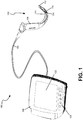
- Fig. 1 illustrates a video laryngoscope system 100 consistent with implementations described herein.
- video laryngoscope system 100 comprises a laryngoscope blade 102, a data cable 104, and a video monitor 106.
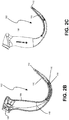
- Fig. 2A is an exploded front perspective view of a single-use laryngoscope blade 102 configured in accordance with embodiments described herein.
- Figs. 2B-2E are an assembled front perspective view, side view, front view, and rear view of blade 102, respectively.
- Camera module 114 may include charge-coupled device (CCD) or Complementary Metal Oxide Silicon (CMOS) configurations that may be placed at a point of angulation of blade portion 110 near its midpoint to provide for advantageous positioning of camera module 114 at some distance from the glottic opening to allow a degree of perspective and wide angle viewing.
- CCD charge-coupled device
- CMOS Complementary Metal Oxide Silicon
- Fig. 3 illustrates a simplified exemplary configuration of one or more components 300 of laryngoscope system 100, such as laryngoscope 102, data cable 104, and video monitor 106.
- component 300 may include bus 310, a processing unit 320, a memory 330, an input device 340, an output device 350, and a communication interface 360.
- Bus 310 may include a path that permits communication among the components 300 of laryngoscope system 100.
- bus 310 may include an I 2 C bus which supports a master/slave relationship between components 300. As described below, in exemplary implementations, the master and slave roles may be negotiated between the components.
- Image capture logic 430 is configured to capture images via camera module 114 based on the most recently updated set of camera settings identified and stored in settings storage 415 and/or received from video monitor 106. The captured images are then forwarded to image output logic 435 for relay to video monitor 106. More specifically, image capture logic 430 is configured to receive image capture control commands from video monitor 106 via data cable 104. In response to an image capture command, image capture logic 430 captures images based on image capture settings stored in settings storage 415. Depending on whether laryngoscope blade 102 is a single-use or reusable blade, image output logic 435 may be integrated within laryngoscope 102 or may include multiple components included within laryngoscope blade 102 and data cable 104.
- Version checking logic 510 includes logic for determining which of data cable 104, video monitor 106, and/or laryngoscope blade 102 has the most up-to-date set of camera settings corresponding to the identified laryngoscope blade 102. As described above in relation to version checking logic 410, version checking logic 510 is similarly configured to alternatively transmit an indication of the version of the set of camera settings stored in settings storage 515 to each of video monitor 106 and laryngoscope blade 102 and similarly receive corresponding information from each of video monitor 106 and laryngoscope blade 102. When it is determined that the version of the set of camera settings stored in settings storage 515 is the most up-to-date, version checking logic 510 may provide the settings to image capture logic 430 in laryngoscope blade 102.
- Data cable 104 may further include image processing logic 520 that performs some or all of the image processing on images captured by camera module 114.
- image processing logic 520 may include a serializer and/or related logic for preparing images captured by camera module 114 for output and display by video monitor 106.
- the color temperature of the images captured using the optimized settings shifts to the more white/blue light and less red as compared to traditional laryngoscope systems.
- the color temperature shifts to the more red light and less white/blue as compared to traditional laryngoscope systems. Consequently, images captured using the above-described optimized settings yield more a significantly more consistent color temperature.
- blade 102 is identified and determined to be authentic (block 704 - YES)
- two or more of the laryngoscope blade 102, data cable 104, and video monitor 106 negotiate to determine which device has the most up-to-date camera settings relative to the identified laryngoscope blade 102 (block 706).
- each component may alternatively assume a "master" role on bus 310 to receive version information from the other components, which are then compared to its current version.
- a device other than laryngoscope blade 102 has the most up-to-date settings. If not (block 708 - NO), the process proceeds to block 712. However, when one of the other devices includes the most up-to-date settings, (block 708 - YES), the settings are forwarded to camera module 114 in laryngoscope blade 102 for use during image capture (block 710).
- laryngoscope blade 102 receives an image capture command from video monitor 106.
- image capture logic 430 in laryngoscope blade 102 may receive a request from control logic 620 in video monitor 106.
- image capturing may initiated automatically upon connection of laryngoscope blade 102 to video monitor 106, or via a control on laryngoscope blade 102.
- image capture logic 430 may capture images based on the settings received or verified in step 708/710 above (block 714).
Landscapes
- Health & Medical Sciences (AREA)
- Life Sciences & Earth Sciences (AREA)
- Surgery (AREA)
- Engineering & Computer Science (AREA)
- Biophysics (AREA)
- Biomedical Technology (AREA)
- Veterinary Medicine (AREA)
- Nuclear Medicine, Radiotherapy & Molecular Imaging (AREA)
- Optics & Photonics (AREA)
- Pathology (AREA)
- Radiology & Medical Imaging (AREA)
- Public Health (AREA)
- General Health & Medical Sciences (AREA)
- Physics & Mathematics (AREA)
- Heart & Thoracic Surgery (AREA)
- Medical Informatics (AREA)
- Molecular Biology (AREA)
- Animal Behavior & Ethology (AREA)
- Signal Processing (AREA)
- Otolaryngology (AREA)
- Physiology (AREA)
- Pulmonology (AREA)
- Multimedia (AREA)
- Endoscopes (AREA)
Description
- Endotracheal intubation provides the current preferred method for control of the airway for mechanical ventilation. The process involves passing an endotracheal tube (ETT) through the mouth, past the tongue, and to and through the vocal cords and larynx to seal the airway. This protects the openness of the airway and protects the airway from aspiration of gastric contents, foreign substances, or secretions.
- Traditional laryngoscopes rely on opening the upper airway to provide a direct line of sight from the medical practitioner's eye to the larynx. Subsequent developments in laryngoscopes utilized fiberoptic bundles, sometimes coupled to video displays. More recently, laryngoscopes with video cameras have made it possible to display the image of the airway anatomy from a remote position, and in some instances allow the intubator to identify the relevant anatomical landmarks without repositioning the patient. This technology reduces the past problem of difficult intubation when the glottis entrance cannot be adequately seen and further reduces the likelihood of infection by medical personnel being unduly close to the nose and mouth of the patient can be avoided.
- Unfortunately, image quality and consistency have reduced the utility of video laryngoscopes and have caused many practitioners to revert to traditional, direct view laryngoscopes. Examples of such systems are in patent documents
US 2011/130627 A1 orUS 2016/226272 A1 . -
-
Fig. 1 is a diagram illustrating a laryngoscope system consistent with embodiments described herein; -
Fig. 2A is an exploded front isometric view of the laryngoscope blade ofFig. 1 ; -
Fig. 2B is a side cross-sectional view of the laryngoscope blade ofFig. 2A ; -
Fig. 2C is a side plan view of the laryngoscope blade ofFig. 2A ; -
Fig. 2D is a front plan view of the laryngoscope blade ofFig. 2A ; -
Fig. 2E is a rear plan view of the laryngoscope blade ofFig. 2A ; -
Fig. 3 illustrates a simplified exemplary configuration of one or more components of the laryngoscope system ofFig. 1 ; -
Fig. 4 is an exemplary functional block diagram of components implemented in a single-use laryngoscope blade consistent with embodiments described herein; -
Fig. 5 is an exemplary functional block diagram of components implemented in a data cable consistent with embodiments described herein; -
Fig. 6 is an exemplary functional block diagram of components implemented in a video monitor consistent with embodiments described herein; and -
Fig. 7 is a flow diagram illustrating exemplary process for capturing images via the video laryngoscope system ofFig. 1 . - The following detailed description refers to the accompanying drawings. The same reference numbers in different drawings may identify the same or similar elements. Also, the following detailed description does not limit the invention, which is defined by the appended claims.
- Several embodiments of a video-based intubation laryngoscope and system are described that allow for examination of the upper airway during intubation. The system employs video laryngoscope embodiments configured to view a patient's glottis, reposition the patient's epiglottis, view the glottic aperture and convey video images of the patient's upper airway anatomy including the glottis and/or glottic aperture and surrounding area to a video monitor viewable by the laryngoscope user.
- Embodiments of the laryngoscope include both single-use (i.e., disposable) and reusable laryngoscope blades that include image capturing and lighting elements. The blade is used to reposition the epiglottis by engagement of the patient's vallecula, or alternatively, directly lifting the epiglottis to reveal the glottic aperture. During and after insertion of the blade, into the patient's upper airway, images obtained from the image capturing elements are conveyed to a video monitor viewable by the laryngoscope user via a data cable. Improved intubation speed and accuracy are accomplished by providing unobstructed, real time or "live" views that are immediately viewable on the video monitor.
- Consistent with embodiments described herein, the laryngoscope blade, the data cable, and the video monitor may each include logic components configured to enable image data to be exchanged between the image capturing element and the video monitor in an efficient and optimized manner.
- In exemplary embodiments, the laryngoscope blade may include logical components for authenticating the blade with other components in the system (e.g., the video monitor and/or data cable) and logging use of the laryngoscope blade (e.g., number of times used, dates/times, etc), and for negotiating with other components in the laryngoscope system (e.g., the blade and the video monitor) to determine which component has the most up-to-date software, which may include optimized camera settings and other instructions relevant to the particular laryngoscope blade.
- In one exemplary embodiment relating to disposable laryngoscope blades, one or more components of the image capturing element may be included within the data cable, thus rendering the remaining image capturing components in the laryngoscope blade less expensive, which is particularly advantageous for a single use device. In such an embodiment, the data cable may include one or more logical components configured to identify when a laryngoscope blade has been connected, which blade has been connected (e.g., type of blade, particular blade, etc.), and to negotiate with other components in the laryngoscope system (e.g., the blade and the video monitor) to determine which component has a most up-to-date software, which may include optimized camera settings and other instructions relevant to the identified laryngoscope blade.
- In other embodiments, such as reusable laryngoscope blades, the logical components of the data cable may be integrated within the laryngoscope blade and negotiation may take place between the laryngoscope blade and the video monitor.
- As briefly described above, exemplary embodiments of the laryngoscope system facilitate the exchange of optimized camera settings between system components. As described in detail below, such optimized camera settings may be specific to each type of laryngoscope blade and may enable the video camera elements within the laryngoscope blade to capture images having a reduced amount of far field dimming in the event that a portion of the patient's anatomy partially obscures the camera view. This allows practitioners to ascertain the relevant anatomy, even where such anatomy is the far field of the image.
-
Fig. 1 illustrates avideo laryngoscope system 100 consistent with implementations described herein. As shown,video laryngoscope system 100 comprises alaryngoscope blade 102, adata cable 104, and avideo monitor 106.Fig. 2A is an exploded front perspective view of a single-use laryngoscope blade 102 configured in accordance with embodiments described herein.Figs. 2B-2E are an assembled front perspective view, side view, front view, and rear view ofblade 102, respectively. - As shown in
Figs. 1-2E ,laryngoscope blade 102 includes ahandle portion 108, ablade portion 110, adistal tip 112, acamera module 114, alight source module 116, a flexible printed circuit board (PCB) 118, and acable interface 120. - During use,
distal tip 112 is used for lifting the epiglottis or for engaging the vallecula of a patient to lift the epiglottis to reveal the glottic aperture.Camera module 114 andlight source module 116 are positioned on a posterior side of theblade portion 110 and are directed towards thedistal tip 112 so as to capture and transmit images of thedistal tip 112 and corresponding patient anatomy tovideo monitor 106 viadata cable 104. -
Camera module 114 may include charge-coupled device (CCD) or Complementary Metal Oxide Silicon (CMOS) configurations that may be placed at a point of angulation ofblade portion 110 near its midpoint to provide for advantageous positioning ofcamera module 114 at some distance from the glottic opening to allow a degree of perspective and wide angle viewing. -
Light source module 116 may include a light emitting diode (LED) lighting array. - As shown in
Fig. 2A , flexible PCB 118 may be configured tocouple cable interface 120 tocamera module 114 andlight source module 116 and may further include or more processors or memory devices, as described below. In other embodiments, PCB 118 may include two or more distinct PCBs joined by wires or other elements. - As described briefly above, in some
embodiments data cable 104 may include one or more components of the image capturing element, such as a serializer component. In such an embodiment, thedata cable 104 may further include one or more logical components configured to identify when a laryngoscope blade has been connected, which blade has been connected, and to negotiate withvideo monitor 106 to determine which of thedata cable 104 and thevideo monitor 106 have the most up-to-date camera settings for use during image capture. In such a single-use blade embodiment, the combination of thedata cable 104 and thelaryngoscope blade 106 may together perform functions corresponding to reusable laryngoscope. - Video monitor 106 may provide power to and initiate image capture from
laryngoscope blade 102 viadata cable 104. For example, as shown inFig. 1 , video monitor 106 may include adisplay 122, and acontrol pad 124. Practitioners (e.g., medical personnel) may interface withvideo monitor 106 during use to initiate image capture, freeze a particular frame, or adjust certain limited settings. Although not shown in the Figures, video monitor 106 may also include a data cable interface for receiving an end ofdata cable 104, a battery or other power source, and a remote monitor interface for enabling the view ofdisplay 122 to be transmitted to one or more other display monitors. -
Fig. 3 illustrates a simplified exemplary configuration of one ormore components 300 oflaryngoscope system 100, such aslaryngoscope 102,data cable 104, andvideo monitor 106. Referring toFig. 3 ,component 300 may includebus 310, aprocessing unit 320, amemory 330, aninput device 340, anoutput device 350, and acommunication interface 360.Bus 310 may include a path that permits communication among thecomponents 300 oflaryngoscope system 100. In one exemplary implementation,bus 310 may include an I2C bus which supports a master/slave relationship betweencomponents 300. As described below, in exemplary implementations, the master and slave roles may be negotiated between the components. -
Processing unit 320 may include one or more processors, microprocessors, or processing logic that may interpret and execute instructions.Memory 330 may include a random access memory (RAM) or another type of dynamic storage device that may store information and instructions for execution by processingunit 320.Memory 330 may also include a read only memory (ROM) device (e.g., an electrically erasable and programmable ROM (EEPROM)) or another type of static storage device that may store static information and instructions for use by processingunit 320. In other embodiments,memory 330 may further include a solid state drive (SDD). -
Input device 340 may include a mechanism that permits a user to input information tolaryngoscope system 100, such as a keyboard, a keypad, a mouse, a pen, a microphone, a touch screen, voice recognition and/or biometric mechanisms, etc.Output device 350 may include a mechanism that outputs information to the user, including a display (e.g., a liquid crystal display (LCD)), a printer, a speaker, etc. In some implementations, a touch screen display may act as both an input device and an output device. In thelaryngoscope system 100 depicted inFig. 1 , onlyvideo monitor 106 may be provided withinput device 340 andoutput device 350, however in other implementations, one or more other components oflaryngoscope system 100 may include such devices. As depicted inFig. 1 ,laryngoscope blade 102 anddata cable 104 may be implemented as headless devices that are not directly provided withinput device 340 oroutput device 350 and may receive commands from, for example,video monitor 106. -
Communication interface 360 may include one or more transceivers that laryngoscope system 100 (e.g., video monitor 106) uses to communicate with other devices via wired, wireless or optical mechanisms. For example,communication interface 360 may include a modem or an Ethernet interface to a local area network (LAN) or other mechanisms for communicating with elements in a communication network (not shown inFig. 1 ). In other embodiments,communication interface 360 may include one or more radio frequency (RF) transmitters, receivers and/or transceivers and one or more antennas for transmitting and receiving RF data via a communication network, such as a wireless LAN or Wi-Fi network. - The exemplary configuration illustrated in
Fig. 3 is provided for simplicity. It should be understood thatlaryngoscope system 100 may include more or fewer components than illustrated inFig. 3 . In an exemplary implementation,laryngoscope system 100 performs operations in response to one ormore processing units 320 executing sequences of instructions contained in a computer-readable medium, such asmemory 330. A computer-readable medium may be defined as a physical or logical memory device. The software instructions may be read intomemory 330 from another computer-readable medium (e.g., a hard disk drive (HDD), SSD, etc.), or from another device viacommunication interface 360. Alternatively, hard-wired circuitry may be used in place of or in combination with software instructions to implement processes consistent with the implementations described herein. Thus, implementations described herein are not limited to any specific combination of hardware circuitry and software. -
Fig. 4 is an exemplary functional block diagram of components implemented in a single-use laryngoscope blade 102 in accordance with an embodiment described herein. In the embodiment ofFig. 4 , all or some of the components may be implemented by processingunit 320 executing software instructions stored inmemory 330. - As shown,
laryngoscope blade 102 may include identification andauthentication logic 405,version checking logic 410,settings storage 415,data logger 420,light source logic 425,image capture logic 430, andimage output logic 435. - Identification and
authentication logic 405 is configured to, upon power up oflaryngoscope blade 102, exchange identification and authentication information withdata cable 104 and/orvideo monitor 106. For example,laryngoscope blade 102 may communicate identification information todata cable 104 via bus 310 (e.g., the I2C bus). In one embodiment, the identification information may comprise information relating to the type oflaryngoscope blade 102, such as the size, application, model, etc. In other implementations, the identification information may include information specific to theparticular laryngoscope blade 102, such as serial number or other uniquely identifying information. - Consistent with embodiments described herein, identification and
authentication logic 405 may provide the identifying information todata cable 104 and video monitor 106 for use in determining whetherlaryngoscope blade 102 is authorized for use with thedata cable 104 andvideo monitor 106. For example, as described below, upon receipt of the identification information fromlaryngoscope blade 102, thedata cable 104 and/orvideo monitor 106 may determine whether thelaryngoscope blade 102 is authorized for use. In this manner, unauthorized, third party laryngoscope blades may not be improperly used with the laryngoscope system described herein. - Furthermore, in other embodiments, identification and
authentication logic 405 may be configured to exchange usage information stored indata logger 420 withvideo monitor 106 viadata cable 104. For example,data logger 420 may be configured to record details regarding usage (e.g., power up) of thelaryngoscope blade 102, such as date, time, and duration oflaryngoscope blade 102. Identification andauthentication logic 405 may, during subsequent power ups, transmit this information to video monitor 106 to for use in determining whether thelaryngoscope blade 102 may be properly used. For example, single-use blades may only be authorized for power-up a predetermined (e.g., <5) number of times, to ensure that the blades are not used outside of their intended purpose. For reusable blades, the usage information stored indata logger 420 may be used to provide historical information, reconditioning recommendations, etc. In other embodiments, the information may be used to monitor a time between uses, to determine whether appropriate sterilization procedures have been followed. -
Version checking logic 410 is configured to, in coordination with similar logic indata cable 104 andvideo monitor 106, determine which component has a most recently updated set of camera settings. For example, because components of medical devices may not be upgradable in the field, providing an integrated upgrade path within the separate components provides an efficient manner for rolling out updated camera settings using only a single factory-updated component, without requiring a dedicated field update process. - Consistent with embodiments described herein, upon power up of
system 100,version checking logic 410 determines which oflaryngoscope blade 102, data cable, 104, orvideo monitor 106 maintains the most recently updated set of camera settings insettings storage 415. Iflaryngoscope blade 102 is not the device with the most recently updated set of camera settings, the device having such settings may transmit the camera settings tolaryngoscope blade 102 or otherwise make the settings available to imagecapture logic 430. - As described briefly above, in one embodiment,
laryngoscope blade 102, data cable, 104, and video monitor 106 may be coupled via an I2C bus, which requires that only one device be in the "master" role at any one time. Generally, since the main control ofsystem 100 is initiated byvideo monitor 106, video monitor 106 is typically in the "master" role. However, consistent with embodiments described herein, upon system power up, each ofvideo monitor 106,data cable 104, and/orlaryngoscope blade 102 may alternatively assume the "master" role for the purposes of sharing information regarding its set of camera settings. -
Light source logic 425 is configured to causelight source module 116 to become illuminated in accordance with settings stored insettings storage 415 or received fromvideo monitor 106. -
Image capture logic 430 is configured to capture images viacamera module 114 based on the most recently updated set of camera settings identified and stored insettings storage 415 and/or received fromvideo monitor 106. The captured images are then forwarded to imageoutput logic 435 for relay tovideo monitor 106. More specifically,image capture logic 430 is configured to receive image capture control commands from video monitor 106 viadata cable 104. In response to an image capture command,image capture logic 430 captures images based on image capture settings stored insettings storage 415. Depending on whetherlaryngoscope blade 102 is a single-use or reusable blade,image output logic 435 may be integrated withinlaryngoscope 102 or may include multiple components included withinlaryngoscope blade 102 anddata cable 104. -
Fig. 5 is an exemplary functional block diagram of components implemented in adata cable 104 in accordance with an embodiment described herein. In the embodiment ofFig. 5 , all or some of the components may be implemented by processingunit 320 executing software instructions stored inmemory 330. - As shown,
data cable 104 may include identification andauthentication logic 505,version checking logic 510, andsettings storage 515 configured similarly to identification andauthentication logic 405,version checking logic 410, andsettings storage 415 described above with respect tolaryngoscope blade 102. For example, identification andauthentication logic 505 may include logic for determining an identity of aconnected laryngoscope blade 102. In some implementations, identification andauthentication logic 505 may be further configured to determine whether theblade 102 is suitable for use withdata cable 104. -
Version checking logic 510 includes logic for determining which ofdata cable 104,video monitor 106, and/orlaryngoscope blade 102 has the most up-to-date set of camera settings corresponding to the identifiedlaryngoscope blade 102. As described above in relation toversion checking logic 410,version checking logic 510 is similarly configured to alternatively transmit an indication of the version of the set of camera settings stored insettings storage 515 to each ofvideo monitor 106 andlaryngoscope blade 102 and similarly receive corresponding information from each ofvideo monitor 106 andlaryngoscope blade 102. When it is determined that the version of the set of camera settings stored insettings storage 515 is the most up-to-date,version checking logic 510 may provide the settings to imagecapture logic 430 inlaryngoscope blade 102. -
Data cable 104 may further includeimage processing logic 520 that performs some or all of the image processing on images captured bycamera module 114. In one embodiment,image processing logic 520 may include a serializer and/or related logic for preparing images captured bycamera module 114 for output and display byvideo monitor 106. -
Fig. 6 is an exemplary functional block diagram of components implemented in avideo monitor 106 in accordance with an embodiment described herein. In the embodiment ofFig. 6 , all or some of the components may be implemented by processingunit 320 executing software instructions stored inmemory 330. - As shown, video monitor 106 may include identification and
authentication logic 605,version checking logic 610,settings storage 615,control logic 620, anddisplay logic 625. Identification andauthentication logic 605,version checking logic 610, andsettings storage 615 may be configured similarly to identification andauthentication logic 405/505,version checking logic 410/510, andsettings storage 415/515 described above with respect tolaryngoscope blade 102 anddata cable 104. For example, identification andauthentication logic 605 may include logic for determining an identity of aconnected laryngoscope blade 102. In some implementations, identification andauthentication logic 605 may be further configured to determine whether theblade 102 is suitable for use withvideo monitor 106. -
Version checking logic 610 includes logic for determining which ofdata cable 104,video monitor 106, and/orlaryngoscope blade 102 has the most up-to-date set of camera settings corresponding to the identifiedlaryngoscope blade 102. As described above in relation toversion checking logic 410,version checking logic 610 is similarly configured to alternatively transmit an indication of the version of the set of camera settings stored insettings storage 615 to each ofdata cable 106 and/orlaryngoscope blade 102 and similarly receiving corresponding information from each ofvideo monitor 106 andlaryngoscope blade 102 before resuming the "master" role on bus 310 (e.g., the I2C bus). When it is determined that the version of the set of camera settings stored insettings storage 615 is the most up-to-date,version checking logic 610 may provide the settings to imagecapture logic 430 inlaryngoscope blade 102. - After
version checking logic 610 completes its check,display logic 625 receives the image data or video signal fromlaryngoscope blade 102 viadata cable 104. As described above, in some implementations, portions of the processing of the image data may be performed byimage processing logic 520 in data cable 204. - Consistent with embodiments described herein, the most up-to-date camera settings stored in one of
settings storage light source module 116 provided immediately adjacent tocamera module 114; 3) extreme red spectrum color bias; 4) frequent extreme swings in lighting brightness caused by unpredictable intrusion of objects into camera field of view when combined with the small usage environment; and 5) high contrast with both near-field and far-field points of interest. Unfortunately, conventional camera settings are not optimized for such an environment and, consequently, images or video quality may suffer and/or pertinent visual details may be lost. - As described above,
camera module 114 comprises a CCD or CMOS device. Consistent with embodiments described herein,camera module 114 includes a plurality of configurable programming registers that allow the image capturing characteristics ofcamera module 114 to be optimized.Settings storage laryngoscope blade 102,data cable 104, and video monitor 106 may be programmed to include one or more sets of customized camera module register values to optimize image and/or video quality in intra-airway environments. For example, different sets of customized camera module register values may be stored for different identified laryngoscope blades, such as blades for adults, versus pediatric blades, etc. - Modern camera modules generally include automatic gain control (AGC) and/or automatic exposure control (AEC), which are designed to improve image quality by automatically boosting the gain and increasing the exposure in low light images so that objects can be seen more clearly and reduce the gain and decrease the exposure in bright images to avoid the subject of the image from being washed out or blurry. Unfortunately, in intra-airway environments, occluding elements, such as the patient's tongue, an endotracheal tube (ETT), etc. may briefly block the camera view causing the AGC/AEC to reduce the gain and decrease the exposure time, thereby losing far field details, which may be necessary for accurate insertion of the laryngoscope or placement of a corresponding ETT.
- Consistent with embodiments described herein, camera module registers or settings relating to the control of AGC and AEC may be optimized. In particular, a setting relating to an upper limit of an AGC/AEC stable operating region may be modified. The upper limit of the AGC/AEC stable operating region refers to how high or bright an incoming image or video signal must become before the camera's gain algorithm mutes or attenuates the signal, by a preset amount, before sending the signal to
video monitor 106. Accordingly, consistent with described embodiments, the upper limit of the AGC/AEC stable operating region may be raised (from its default) so that the "trigger point" of upper limit gain attenuation does not occur until the incoming signal significantly increases. The consequence is that any intruding near-field object, such as a patient's tongue or a medical intubation tube, would need to either block a larger portion of the field of view or remain in the field of view much longer. - Consistent with embodiments described herein, a setting relating to the lower limit of the AGC/AEC stable operating region may also be modified. This setting controls how low or dim an incoming signal must achieve before the camera's gain algorithm boosts the signal sent to host. Because a primary objective for intra-airway image capture is to ensure that a patient's far-field vocal chords are visible most of the time during an intubation procedure, the value for the lower limit of the AGC/AEC stable operating region may be increased (from its default) to consequently maintain the "window" in which attenuation is active to a minimum.
- In some embodiments, one or more settings relate to or identify the maximum gain boost that can be applied when the incoming signal drops below the AGC/AEC lower limit. As described above, since the AGC/AEC lower limit is raised in accordance with the described embodiments, the effect is that gain boost would be triggered at gain amounts higher than traditionally applied. This may cause images to overexpose even at moderate lighting levels, since the lower limit was now near or above normal lighting levels. To counter this, the automatic gain ceiling maximum AGC value setting may be lowered (from its default) to limit the maximum boost that
camera module 114 can apply. This helps manage the over exposure effect and bring it to an acceptable level.Consistent with embodiments described herein, images captured using the above-described optimized settings results in far end vocal cord viewing that is, for example, approximately 25 to 166% brighter than traditional laryngoscope systems. Further, images captured using the above-described optimized settings result in near end reflectance of, for example, approximately 29% over traditional laryngoscope systems. For the overall field of view, images captured using the above-described optimized settings result in a brightness increases of between 50 and 279% over traditional laryngoscope systems for adults and approximately 6.4% for neonatal patients. Additionally, when imaging the vocal cords, the color temperature of the images captured using the optimized settings shifts to the more white/blue light and less red as compared to traditional laryngoscope systems. However, when imaging the overall field, the color temperature shifts to the more red light and less white/blue as compared to traditional laryngoscope systems. Consequently, images captured using the above-described optimized settings yield more a significantly more consistent color temperature. -
Fig. 7 is a flow diagram illustrating anexemplary process 700 for capturing images viavideo laryngoscope system 100 described herein. In one embodiment,process 700 may begin whenlaryngoscope blade 102 is plugged intodata cable 104,data cable 104 is plugged intovideo monitor 106, and video monitor 106 is powered up (block 702). - At
block 704,data cable 104 and/or video monitor 106identify laryngoscope blade 102 and determines whether it is authentic. For example, as described above, identification andauthentication logic 605 requests and receives blade identification information fromlaryngoscope blade 102 and determines whetherblade 102 is authentic and, potentially, that it has not exceeded its authorized number of uses. If not (block 704 - NO), the process ends and a notification or alert is output via video monitor 106 (block 705). - However, if
blade 102 is identified and determined to be authentic (block 704 - YES), two or more of thelaryngoscope blade 102,data cable 104, and video monitor 106 negotiate to determine which device has the most up-to-date camera settings relative to the identified laryngoscope blade 102 (block 706). For example, as described above, each component may alternatively assume a "master" role onbus 310 to receive version information from the other components, which are then compared to its current version. - At
block 708, it is determined whether a device other thanlaryngoscope blade 102 has the most up-to-date settings. If not (block 708 - NO), the process proceeds to block 712. However, when one of the other devices includes the most up-to-date settings, (block 708 - YES), the settings are forwarded tocamera module 114 inlaryngoscope blade 102 for use during image capture (block 710). - At
block 712,laryngoscope blade 102 receives an image capture command fromvideo monitor 106. For example,image capture logic 430 inlaryngoscope blade 102 may receive a request fromcontrol logic 620 invideo monitor 106. In other embodiments, image capturing may initiated automatically upon connection oflaryngoscope blade 102 to video monitor 106, or via a control onlaryngoscope blade 102. In any event, once initiated,image capture logic 430 may capture images based on the settings received or verified instep 708/710 above (block 714). - Captured images are forwarded to video monitor 106 via data cable 104 (block 716). For example,
image output logic 435 inlaryngoscope blade 102 may output the image data captured bycamera module 114 todata cable 104. As described above, in some implementations, some or all image processing on the image data may be performed byimage processing logic 520 indata cable 104. - Processed image or video data is received by video monitor 106 (block 718) and output via display 122 (block 720).
- The foregoing description of embodiments provides illustration, but is not intended to be exhaustive or to limit the embodiments to the precise form disclosed. In the preceding description, various embodiments have been described with reference to the accompanying drawings. However, various modifications and changes may be made thereto, and additional embodiments may be implemented, without departing from the broader scope of the invention as set forth in the claims that follow. The description and drawings are accordingly to be regarded as illustrative rather than restrictive.
- As set forth in this description and illustrated by the drawings, reference is made to "an exemplary embodiment," "an embodiment," "embodiments," etc., which may include a particular feature, structure or characteristic in connection with an embodiment(s). However, the use of the phrase or term "an embodiment," "embodiments," etc., in various places in the specification does not necessarily refer to all embodiments described, nor does it necessarily refer to the same embodiment, nor are separate or alternative embodiments necessarily mutually exclusive of other embodiment(s). The same applies to the term "implementation," "implementations," etc.
- The terms "a," "an," and "the" are intended to be interpreted to include one or more items. Further, the phrase "based on" is intended to be interpreted as "based, at least in part, on," unless explicitly stated otherwise. The term "and/or" is intended to be interpreted to include any and all combinations of one or more of the associated items.
- The word "exemplary" is used herein to mean "serving as an example." Any embodiment or implementation described as "exemplary" is not necessarily to be construed as preferred or advantageous over other embodiments or implementations.
- Use of ordinal terms such as "first," "second," "third," etc., in the claims to modify a claim element does not by itself connote any priority, precedence, or order of one claim element over another, the temporal order in which acts of a method are performed, the temporal order in which instructions executed by a device are performed, etc., but are used merely as labels to distinguish one claim element having a certain name from another element having a same name (but for use of the ordinal term) to distinguish the claim elements.
- No element, act, or instruction described in the present application should be construed as critical or essential to the embodiments described herein unless explicitly described as such.
Claims (15)
- A video laryngoscope system (100) comprising:a video monitor (106), a data cable (104); and a laryngoscope blade (102) coupled to the video monitor via the data cable, the laryngoscope blade comprising at least an image capture device (114), a light source (116), a processor (320); wherein the video laryngoscope blade, the video monitor and the data cable each include storage for storing image capture settings;wherein at least one of the video monitor or the data cable comprise logic to:identify the laryngoscope blade;determine which of the laryngoscope blade, the video monitor, and the data cable have a most up-to-date set of image capture settings for the identified laryngoscope blade; andtransmit the most up-to-date set of image capture settings to the laryngoscope blade for use in capturing intra-airway images, when one of the video monitor or the data cable include the most up-to-date set of image capture settings.
- The video laryngoscope system of claim 1, wherein the logic to determine which of the laryngoscope blade, the video monitor, and the data cable have a most up-to-date set of image capture settings based on the identified laryngoscope blade, further comprises logic to alternate between master and slave roles to pass image capture settings information across a shared bus.
- The video laryngoscope system of claim 2, wherein the logic to alternate between master and slave roles is further configured to:determine whether one of the video monitor or the data cable have the most up-to-date set of image capture settings based on the identified laryngoscope blade, andforward, based on the determination, the most up-to-date set of image capture settings to the laryngoscope blade.
- The video laryngoscope system of any of the preceding claims 1-3,
wherein the laryngoscope blade comprises a single use laryngoscope blade having image processing capabilities less than image processing capabilities for a reusable laryngoscope blade, and
wherein the data cable comprises image processing logic corresponding to the image processing capabilities of the single use laryngoscope blade. - The video laryngoscope system of any of the preceding claims 1-4, wherein the image capture settings include optimized automatic gain control (AGC) settings for reducing far field dimming in the presence of a near field obstruction in the field of view.
- The video laryngoscope system of claim 5, wherein the optimized automatic gain control settings comprise:a value for an upper limit of an AGC stable operating region that is raised from its default value;a value for a lower limit of an AGC stable operating region that is raised from its default value; anda value for a ceiling of the maximum AGC that is lowered from its default value.
- The video laryngoscope system of any of the preceding claims 1-6, wherein the image capture settings include optimized color temperature settings.
- The video laryngoscope system of any of the preceding claims 1-7, wherein the logic to identify the laryngoscope blade is further configured to:receive identification information from the laryngoscope blade; andcompare the received identification information to information stored on the video monitor or data cable and associated with image capture settings.
- The video laryngoscope system of claim 8, wherein the identification information comprises one or more of model or size information.
- The video laryngoscope system of any of the preceding claims 1-9, wherein the laryngoscope blade further comprises:
data logging logic for storing information regarding one or more of: a number of uses of the laryngoscope blade, date and time information for the number of uses, or duration of use for the number of uses. - A method for updating image capture settings of a video laryngoscope blade, comprising:connecting the video laryngoscope blade to a video monitor via a data cable,wherein the video laryngoscope blade, the video monitor, and the data cable each include storage for storing image capture settings;determining, by either of the video monitor and the data cable, an identity of the connected video laryngoscope blade;determining which of the video laryngoscope blade, the video monitor, or the data cable have a most up-to-date set of image capture settings for the identified video laryngoscope blade;forwarding the most up-to-date set of image capture settings to the video laryngoscope blade, when one of the video monitor or the data cable include the most up-to-date set of image capture settings; andupdating the stored image capture settings on the video laryngoscope blade based on the received most up-to-date set of image capture settings.
- The method of claim 11, wherein the most up-to-date image capture settings include optimized automatic gain control (AGC) settings based on the identified video laryngoscope blade for reducing far field dimming in the presence of a near field obstruction in the field of view.
- The method of claim 12, wherein the optimized automatic gain control settings comprise:a value for an upper limit of an AGC stable operating region that is raised from its default value;a value for a lower limit of an AGC stable operating region that is raised from its default value; anda value for a ceiling of the maximum AGC that is lowered from its default value.
- The method of any of the claims 11-13, wherein the most up-to-date image capture settings include optimized color temperature settings based on the identified video laryngoscope blade.
- The method of any of the claims 11-14, wherein determining the identity of the connected video laryngoscope blade further comprises:receiving identification information from the laryngoscope blade; andcomparing the received identification information to information stored on the video monitor or data cable and associated with image capture settings.
Applications Claiming Priority (1)
| Application Number | Priority Date | Filing Date | Title |
|---|---|---|---|
| US201762444181P | 2017-01-09 | 2017-01-09 |
Publications (2)
| Publication Number | Publication Date |
|---|---|
| EP3348183A1 EP3348183A1 (en) | 2018-07-18 |
| EP3348183B1 true EP3348183B1 (en) | 2019-12-25 |
Family
ID=60937649
Family Applications (1)
| Application Number | Title | Priority Date | Filing Date |
|---|---|---|---|
| EP18150568.6A Active EP3348183B1 (en) | 2017-01-09 | 2018-01-08 | Upgradable video laryngoscope system exhibiting reduced far end dimming |
Country Status (5)
| Country | Link |
|---|---|
| US (4) | US10820792B2 (en) |
| EP (1) | EP3348183B1 (en) |
| AU (1) | AU2018200147B2 (en) |
| CA (1) | CA2991349C (en) |
| ES (1) | ES2775441T3 (en) |
Families Citing this family (10)
| Publication number | Priority date | Publication date | Assignee | Title |
|---|---|---|---|---|
| CN110651395B (en) * | 2017-05-30 | 2021-08-31 | 华为技术有限公司 | Multiple Antenna Systems |
| WO2020146894A1 (en) * | 2019-01-13 | 2020-07-16 | Stryker Corporation | Systems and methods for connecting a medical imaging device to a medical imaging controller |
| US11759110B2 (en) * | 2019-11-18 | 2023-09-19 | Koninklijke Philips N.V. | Camera view and screen scraping for information extraction from imaging scanner consoles |
| JP7792354B2 (en) | 2020-05-19 | 2025-12-25 | スピロ・ロボティクス・インコーポレーテッド | Robot-assisted navigation and control for airway management procedures, assemblies, and systems |
| US12597503B2 (en) | 2021-03-05 | 2026-04-07 | Ambu A/S | Medical visualization devices and systems |
| EP4301200A1 (en) | 2021-03-05 | 2024-01-10 | Ambu A/S | Medical visualisation system and associated methods and systems |
| US20240122445A1 (en) * | 2021-03-05 | 2024-04-18 | Ambu A/S | Auxiliary component with memory for a medical visualisation device |
| JP2025514665A (en) | 2022-04-10 | 2025-05-09 | スピロ・ロボティクス・インコーポレーテッド | Disposable controls, reusable devices, and how to use them |
| CN116942067B (en) * | 2023-06-19 | 2024-03-22 | 珠海微视医用科技有限公司 | Disposable blade laryngoscope and processing method thereof |
| US20250025038A1 (en) * | 2023-07-18 | 2025-01-23 | Covidien Lp | Video laryngoscope with automatic blade detection |
Family Cites Families (37)
| Publication number | Priority date | Publication date | Assignee | Title |
|---|---|---|---|---|
| JP2821141B2 (en) | 1988-07-28 | 1998-11-05 | オリンパス光学工業株式会社 | Automatic dimming control device for endoscope |
| DE3928052C1 (en) | 1989-08-25 | 1990-09-27 | Richard Wolf Gmbh, 7134 Knittlingen, De | |
| US6147705A (en) | 1996-08-20 | 2000-11-14 | Welch Allyn Inc. | Apparatus and method for video colposcope with electronic green filter |
| IL120135A0 (en) | 1997-02-03 | 1997-06-10 | Dentop Systems Ltd | A video system for three dimensional imaging and photogrammetry |
| US6462770B1 (en) * | 1998-04-20 | 2002-10-08 | Xillix Technologies Corp. | Imaging system with automatic gain control for reflectance and fluorescence endoscopy |
| US7136098B1 (en) | 1998-10-23 | 2006-11-14 | Smith & Nephew, Inc. | Image illumination optimizing |
| JP2000193896A (en) | 1998-12-28 | 2000-07-14 | Asahi Optical Co Ltd | Endoscope light intensity control device |
| US6767321B2 (en) | 1999-10-04 | 2004-07-27 | Robert Czarnek | Stereo laparoscope with discrete working distance |
| JP4338337B2 (en) | 2001-06-15 | 2009-10-07 | Hoya株式会社 | Electronic endoscope apparatus for performing color adjustment processing and video scope of electronic endoscope apparatus |
| US8199188B2 (en) | 2001-11-09 | 2012-06-12 | Karl Storz Imaging, Inc. | Video imaging system with a camera control unit |
| US8723936B2 (en) | 2002-03-12 | 2014-05-13 | Karl Storz Imaging, Inc. | Wireless camera coupling with rotatable coupling |
| DE10214809A1 (en) | 2002-04-04 | 2003-10-23 | Wolf Gmbh Richard | Solid state video camera and brightness control therefor |
| EP1492441B1 (en) | 2002-04-10 | 2013-04-03 | Karl Storz Endoscopy-America, Inc. | Apparatus and method for powering portable battery operated light sources |
| US6747808B2 (en) | 2002-10-04 | 2004-06-08 | Hewlett-Packard Development Company, L.P. | Electronic imaging device focusing |
| JP4394356B2 (en) | 2003-02-07 | 2010-01-06 | Hoya株式会社 | Electronic endoscope device |
| JP4139276B2 (en) | 2003-06-17 | 2008-08-27 | オリンパス株式会社 | Electronic endoscope apparatus and signal processing apparatus |
| JP4343594B2 (en) | 2003-06-23 | 2009-10-14 | オリンパス株式会社 | Endoscope device |
| JP4349856B2 (en) | 2003-07-07 | 2009-10-21 | Hoya株式会社 | Electronic endoscope device capable of automatic dimming |
| EP1752083A4 (en) | 2004-05-24 | 2013-10-16 | Olympus Corp | Light source device for endoscope |
| US7547277B2 (en) | 2005-12-15 | 2009-06-16 | Microvision, Inc. | Method and apparatus for calibrating an endoscope system |
| JP4895834B2 (en) | 2007-01-23 | 2012-03-14 | Hoya株式会社 | Image processing device |
| WO2008115547A1 (en) | 2007-03-19 | 2008-09-25 | Sti Medical Systems, Llc | A method of automated image color calibration |
| JP5318861B2 (en) | 2007-06-12 | 2013-10-16 | エーブイエヌ・メディカル・テクノロジーズ,エルエルシー | Airway management |
| JP5424570B2 (en) | 2008-04-10 | 2014-02-26 | Hoya株式会社 | Electronic endoscope processor, videoscope, and electronic endoscope apparatus |
| WO2010045406A2 (en) | 2008-10-15 | 2010-04-22 | The Regents Of The University Of California | Camera system with autonomous miniature camera and light source assembly and method for image enhancement |
| JP5467756B2 (en) | 2008-11-14 | 2014-04-09 | Hoya株式会社 | Endoscope device |
| US9986902B2 (en) * | 2009-03-31 | 2018-06-05 | Dilon Technologies, Inc. | Laryngoscope, laryngoscope arm and laryngoscope system |
| WO2010134413A1 (en) | 2009-05-18 | 2010-11-25 | オリンパスメディカルシステムズ株式会社 | Endoscope device |
| JP5325725B2 (en) | 2009-09-24 | 2013-10-23 | 富士フイルム株式会社 | Endoscope device |
| US9179831B2 (en) * | 2009-11-30 | 2015-11-10 | King Systems Corporation | Visualization instrument |
| JP2011176671A (en) * | 2010-02-25 | 2011-09-08 | Hoya Corp | Imaging system |
| JP6165624B2 (en) | 2010-03-25 | 2017-07-19 | デピュー シンセス プロダクツ, インコーポレーテッドDePuy Synthes Products, Inc. | System and method for providing a medical disposable imaging device |
| WO2011141753A1 (en) * | 2010-05-13 | 2011-11-17 | Aircraft Medical Limited | Electrical device power management |
| US8878920B2 (en) | 2011-07-12 | 2014-11-04 | Karl Storz Imaging, Inc. | Method and apparatus for protection from high intensity light |
| US8944596B2 (en) | 2011-11-09 | 2015-02-03 | Welch Allyn, Inc. | Digital-based medical devices |
| WO2013146014A1 (en) | 2012-03-29 | 2013-10-03 | オリンパスメディカルシステムズ株式会社 | Endoscope system |
| CN103400090B (en) * | 2013-05-27 | 2015-12-23 | 佳能士科技有限公司 | A kind of laryngeal mirror lens access times detection method and device |
-
2018
- 2018-01-08 EP EP18150568.6A patent/EP3348183B1/en active Active
- 2018-01-08 CA CA2991349A patent/CA2991349C/en active Active
- 2018-01-08 ES ES18150568T patent/ES2775441T3/en active Active
- 2018-01-08 AU AU2018200147A patent/AU2018200147B2/en active Active
- 2018-01-08 US US15/864,416 patent/US10820792B2/en active Active
-
2020
- 2020-09-29 US US17/036,944 patent/US11883008B2/en active Active
-
2023
- 2023-12-15 US US18/541,726 patent/US20240115122A1/en active Pending
- 2023-12-15 US US18/541,775 patent/US20240108207A1/en active Pending
Non-Patent Citations (1)
| Title |
|---|
| None * |
Also Published As
| Publication number | Publication date |
|---|---|
| CA2991349A1 (en) | 2018-07-09 |
| US11883008B2 (en) | 2024-01-30 |
| US20180192864A1 (en) | 2018-07-12 |
| ES2775441T3 (en) | 2020-07-27 |
| AU2018200147A1 (en) | 2018-07-26 |
| US20240108207A1 (en) | 2024-04-04 |
| AU2018200147B2 (en) | 2018-11-15 |
| US10820792B2 (en) | 2020-11-03 |
| US20210007595A1 (en) | 2021-01-14 |
| EP3348183A1 (en) | 2018-07-18 |
| CA2991349C (en) | 2020-07-14 |
| US20240115122A1 (en) | 2024-04-11 |
Similar Documents
| Publication | Publication Date | Title |
|---|---|---|
| US20240108207A1 (en) | Methods and systems for upgradable video medical device system | |
| US12082787B2 (en) | Video laryngoscope systems and methods | |
| JP4717843B2 (en) | Wireless optical endoscopic device | |
| EP2547093B1 (en) | Method and apparatus for protection from high intensity light | |
| US20150374206A1 (en) | Methods and Systems for Managing Information Generated From and Transmitted To An Endoscopic System | |
| US11839362B2 (en) | Visualization devices and methods for otologic procedures | |
| US20210209398A1 (en) | Medical image processing apparatus, processor device, medical image processing method, and program | |
| US8284244B2 (en) | Signal processing system | |
| US10667669B2 (en) | Endoscope system having various combinations of light sources | |
| US12557979B2 (en) | Video laryngoscope with window for infrared pairing | |
| JP2018166988A (en) | Electronic endoscope system, electronic endoscope, treatment instrument, and endoscope controller | |
| US11627243B2 (en) | Handheld wireless endoscope image streaming apparatus | |
| JP2015047459A (en) | Endoscope system | |
| US20240115111A1 (en) | Medical visualisation system and associated methods and systems | |
| JP2026503936A (en) | Information management and inventory tracking for medical devices | |
| WO2023148695A1 (en) | Video laryngoscope with window for infrared pairing |
Legal Events
| Date | Code | Title | Description |
|---|---|---|---|
| PUAI | Public reference made under article 153(3) epc to a published international application that has entered the european phase |
Free format text: ORIGINAL CODE: 0009012 |
|
| STAA | Information on the status of an ep patent application or granted ep patent |
Free format text: STATUS: THE APPLICATION HAS BEEN PUBLISHED |
|
| AK | Designated contracting states |
Kind code of ref document: A1 Designated state(s): AL AT BE BG CH CY CZ DE DK EE ES FI FR GB GR HR HU IE IS IT LI LT LU LV MC MK MT NL NO PL PT RO RS SE SI SK SM TR |
|
| AX | Request for extension of the european patent |
Extension state: BA ME |
|
| STAA | Information on the status of an ep patent application or granted ep patent |
Free format text: STATUS: REQUEST FOR EXAMINATION WAS MADE |
|
| 17P | Request for examination filed |
Effective date: 20190118 |
|
| RBV | Designated contracting states (corrected) |
Designated state(s): AL AT BE BG CH CY CZ DE DK EE ES FI FR GB GR HR HU IE IS IT LI LT LU LV MC MK MT NL NO PL PT RO RS SE SI SK SM TR |
|
| GRAP | Despatch of communication of intention to grant a patent |
Free format text: ORIGINAL CODE: EPIDOSNIGR1 |
|
| STAA | Information on the status of an ep patent application or granted ep patent |
Free format text: STATUS: GRANT OF PATENT IS INTENDED |
|
| INTG | Intention to grant announced |
Effective date: 20190722 |
|
| GRAS | Grant fee paid |
Free format text: ORIGINAL CODE: EPIDOSNIGR3 |
|
| GRAA | (expected) grant |
Free format text: ORIGINAL CODE: 0009210 |
|
| STAA | Information on the status of an ep patent application or granted ep patent |
Free format text: STATUS: THE PATENT HAS BEEN GRANTED |
|
| AK | Designated contracting states |
Kind code of ref document: B1 Designated state(s): AL AT BE BG CH CY CZ DE DK EE ES FI FR GB GR HR HU IE IS IT LI LT LU LV MC MK MT NL NO PL PT RO RS SE SI SK SM TR |
|
| REG | Reference to a national code |
Ref country code: GB Ref legal event code: FG4D |
|
| REG | Reference to a national code |
Ref country code: CH Ref legal event code: EP |
|
| REG | Reference to a national code |
Ref country code: AT Ref legal event code: REF Ref document number: 1216198 Country of ref document: AT Kind code of ref document: T Effective date: 20200115 |
|
| REG | Reference to a national code |
Ref country code: DE Ref legal event code: R096 Ref document number: 602018001690 Country of ref document: DE |
|
| REG | Reference to a national code |
Ref country code: IE Ref legal event code: FG4D |
|
| REG | Reference to a national code |
Ref country code: NL Ref legal event code: FP |
|
| REG | Reference to a national code |
Ref country code: SE Ref legal event code: TRGR |
|
| PG25 | Lapsed in a contracting state [announced via postgrant information from national office to epo] |
Ref country code: GR Free format text: LAPSE BECAUSE OF FAILURE TO SUBMIT A TRANSLATION OF THE DESCRIPTION OR TO PAY THE FEE WITHIN THE PRESCRIBED TIME-LIMIT Effective date: 20200326 Ref country code: NO Free format text: LAPSE BECAUSE OF FAILURE TO SUBMIT A TRANSLATION OF THE DESCRIPTION OR TO PAY THE FEE WITHIN THE PRESCRIBED TIME-LIMIT Effective date: 20200325 Ref country code: BG Free format text: LAPSE BECAUSE OF FAILURE TO SUBMIT A TRANSLATION OF THE DESCRIPTION OR TO PAY THE FEE WITHIN THE PRESCRIBED TIME-LIMIT Effective date: 20200325 Ref country code: FI Free format text: LAPSE BECAUSE OF FAILURE TO SUBMIT A TRANSLATION OF THE DESCRIPTION OR TO PAY THE FEE WITHIN THE PRESCRIBED TIME-LIMIT Effective date: 20191225 Ref country code: LT Free format text: LAPSE BECAUSE OF FAILURE TO SUBMIT A TRANSLATION OF THE DESCRIPTION OR TO PAY THE FEE WITHIN THE PRESCRIBED TIME-LIMIT Effective date: 20191225 Ref country code: LV Free format text: LAPSE BECAUSE OF FAILURE TO SUBMIT A TRANSLATION OF THE DESCRIPTION OR TO PAY THE FEE WITHIN THE PRESCRIBED TIME-LIMIT Effective date: 20191225 |
|
| REG | Reference to a national code |
Ref country code: LT Ref legal event code: MG4D |
|
| PG25 | Lapsed in a contracting state [announced via postgrant information from national office to epo] |
Ref country code: HR Free format text: LAPSE BECAUSE OF FAILURE TO SUBMIT A TRANSLATION OF THE DESCRIPTION OR TO PAY THE FEE WITHIN THE PRESCRIBED TIME-LIMIT Effective date: 20191225 Ref country code: RS Free format text: LAPSE BECAUSE OF FAILURE TO SUBMIT A TRANSLATION OF THE DESCRIPTION OR TO PAY THE FEE WITHIN THE PRESCRIBED TIME-LIMIT Effective date: 20191225 |
|
| PG25 | Lapsed in a contracting state [announced via postgrant information from national office to epo] |
Ref country code: AL Free format text: LAPSE BECAUSE OF FAILURE TO SUBMIT A TRANSLATION OF THE DESCRIPTION OR TO PAY THE FEE WITHIN THE PRESCRIBED TIME-LIMIT Effective date: 20191225 |
|
| REG | Reference to a national code |
Ref country code: ES Ref legal event code: FG2A Ref document number: 2775441 Country of ref document: ES Kind code of ref document: T3 Effective date: 20200727 |
|
| PG25 | Lapsed in a contracting state [announced via postgrant information from national office to epo] |
Ref country code: RO Free format text: LAPSE BECAUSE OF FAILURE TO SUBMIT A TRANSLATION OF THE DESCRIPTION OR TO PAY THE FEE WITHIN THE PRESCRIBED TIME-LIMIT Effective date: 20191225 Ref country code: PT Free format text: LAPSE BECAUSE OF FAILURE TO SUBMIT A TRANSLATION OF THE DESCRIPTION OR TO PAY THE FEE WITHIN THE PRESCRIBED TIME-LIMIT Effective date: 20200520 Ref country code: CZ Free format text: LAPSE BECAUSE OF FAILURE TO SUBMIT A TRANSLATION OF THE DESCRIPTION OR TO PAY THE FEE WITHIN THE PRESCRIBED TIME-LIMIT Effective date: 20191225 Ref country code: EE Free format text: LAPSE BECAUSE OF FAILURE TO SUBMIT A TRANSLATION OF THE DESCRIPTION OR TO PAY THE FEE WITHIN THE PRESCRIBED TIME-LIMIT Effective date: 20191225 |
|
| PG25 | Lapsed in a contracting state [announced via postgrant information from national office to epo] |
Ref country code: SM Free format text: LAPSE BECAUSE OF FAILURE TO SUBMIT A TRANSLATION OF THE DESCRIPTION OR TO PAY THE FEE WITHIN THE PRESCRIBED TIME-LIMIT Effective date: 20191225 Ref country code: IS Free format text: LAPSE BECAUSE OF FAILURE TO SUBMIT A TRANSLATION OF THE DESCRIPTION OR TO PAY THE FEE WITHIN THE PRESCRIBED TIME-LIMIT Effective date: 20200425 Ref country code: SK Free format text: LAPSE BECAUSE OF FAILURE TO SUBMIT A TRANSLATION OF THE DESCRIPTION OR TO PAY THE FEE WITHIN THE PRESCRIBED TIME-LIMIT Effective date: 20191225 |
|
| REG | Reference to a national code |
Ref country code: DE Ref legal event code: R097 Ref document number: 602018001690 Country of ref document: DE |
|
| PG25 | Lapsed in a contracting state [announced via postgrant information from national office to epo] |
Ref country code: MC Free format text: LAPSE BECAUSE OF FAILURE TO SUBMIT A TRANSLATION OF THE DESCRIPTION OR TO PAY THE FEE WITHIN THE PRESCRIBED TIME-LIMIT Effective date: 20191225 |
|
| PG25 | Lapsed in a contracting state [announced via postgrant information from national office to epo] |
Ref country code: LU Free format text: LAPSE BECAUSE OF NON-PAYMENT OF DUE FEES Effective date: 20200108 Ref country code: DK Free format text: LAPSE BECAUSE OF FAILURE TO SUBMIT A TRANSLATION OF THE DESCRIPTION OR TO PAY THE FEE WITHIN THE PRESCRIBED TIME-LIMIT Effective date: 20191225 |
|
| PLBE | No opposition filed within time limit |
Free format text: ORIGINAL CODE: 0009261 |
|
| STAA | Information on the status of an ep patent application or granted ep patent |
Free format text: STATUS: NO OPPOSITION FILED WITHIN TIME LIMIT |
|
| REG | Reference to a national code |
Ref country code: AT Ref legal event code: MK05 Ref document number: 1216198 Country of ref document: AT Kind code of ref document: T Effective date: 20191225 |
|
| PG25 | Lapsed in a contracting state [announced via postgrant information from national office to epo] |
Ref country code: SI Free format text: LAPSE BECAUSE OF FAILURE TO SUBMIT A TRANSLATION OF THE DESCRIPTION OR TO PAY THE FEE WITHIN THE PRESCRIBED TIME-LIMIT Effective date: 20191225 |
|
| 26N | No opposition filed |
Effective date: 20200928 |
|
| PG25 | Lapsed in a contracting state [announced via postgrant information from national office to epo] |
Ref country code: IE Free format text: LAPSE BECAUSE OF NON-PAYMENT OF DUE FEES Effective date: 20200108 Ref country code: AT Free format text: LAPSE BECAUSE OF FAILURE TO SUBMIT A TRANSLATION OF THE DESCRIPTION OR TO PAY THE FEE WITHIN THE PRESCRIBED TIME-LIMIT Effective date: 20191225 |
|
| PG25 | Lapsed in a contracting state [announced via postgrant information from national office to epo] |
Ref country code: PL Free format text: LAPSE BECAUSE OF FAILURE TO SUBMIT A TRANSLATION OF THE DESCRIPTION OR TO PAY THE FEE WITHIN THE PRESCRIBED TIME-LIMIT Effective date: 20191225 |
|
| PG25 | Lapsed in a contracting state [announced via postgrant information from national office to epo] |
Ref country code: TR Free format text: LAPSE BECAUSE OF FAILURE TO SUBMIT A TRANSLATION OF THE DESCRIPTION OR TO PAY THE FEE WITHIN THE PRESCRIBED TIME-LIMIT Effective date: 20191225 Ref country code: MT Free format text: LAPSE BECAUSE OF FAILURE TO SUBMIT A TRANSLATION OF THE DESCRIPTION OR TO PAY THE FEE WITHIN THE PRESCRIBED TIME-LIMIT Effective date: 20191225 Ref country code: CY Free format text: LAPSE BECAUSE OF FAILURE TO SUBMIT A TRANSLATION OF THE DESCRIPTION OR TO PAY THE FEE WITHIN THE PRESCRIBED TIME-LIMIT Effective date: 20191225 |
|
| PG25 | Lapsed in a contracting state [announced via postgrant information from national office to epo] |
Ref country code: MK Free format text: LAPSE BECAUSE OF FAILURE TO SUBMIT A TRANSLATION OF THE DESCRIPTION OR TO PAY THE FEE WITHIN THE PRESCRIBED TIME-LIMIT Effective date: 20191225 |
|
| P01 | Opt-out of the competence of the unified patent court (upc) registered |
Effective date: 20230527 |
|
| REG | Reference to a national code |
Ref country code: CH Ref legal event code: U11 Free format text: ST27 STATUS EVENT CODE: U-0-0-U10-U11 (AS PROVIDED BY THE NATIONAL OFFICE) Effective date: 20260201 |
|
| PGFP | Annual fee paid to national office [announced via postgrant information from national office to epo] |
Ref country code: NL Payment date: 20260121 Year of fee payment: 9 |
|
| PGFP | Annual fee paid to national office [announced via postgrant information from national office to epo] |
Ref country code: SE Payment date: 20260121 Year of fee payment: 9 |
|
| PGFP | Annual fee paid to national office [announced via postgrant information from national office to epo] |
Ref country code: GB Payment date: 20260121 Year of fee payment: 9 |
|
| PGFP | Annual fee paid to national office [announced via postgrant information from national office to epo] |
Ref country code: ES Payment date: 20260217 Year of fee payment: 9 |
|
| PGFP | Annual fee paid to national office [announced via postgrant information from national office to epo] |
Ref country code: DE Payment date: 20260120 Year of fee payment: 9 |
|
| PGFP | Annual fee paid to national office [announced via postgrant information from national office to epo] |
Ref country code: BE Payment date: 20260121 Year of fee payment: 9 Ref country code: IT Payment date: 20260130 Year of fee payment: 9 |
|
| PGFP | Annual fee paid to national office [announced via postgrant information from national office to epo] |
Ref country code: FR Payment date: 20260123 Year of fee payment: 9 |
|
| PGFP | Annual fee paid to national office [announced via postgrant information from national office to epo] |
Ref country code: CH Payment date: 20260201 Year of fee payment: 9 |