EP3347069B1 - Blood mixer for a blood collecting bag - Google Patents
Blood mixer for a blood collecting bag Download PDFInfo
- Publication number
- EP3347069B1 EP3347069B1 EP16844808.2A EP16844808A EP3347069B1 EP 3347069 B1 EP3347069 B1 EP 3347069B1 EP 16844808 A EP16844808 A EP 16844808A EP 3347069 B1 EP3347069 B1 EP 3347069B1
- Authority
- EP
- European Patent Office
- Prior art keywords
- blood
- mixer
- tube
- collecting bag
- bag
- Prior art date
- Legal status (The legal status is an assumption and is not a legal conclusion. Google has not performed a legal analysis and makes no representation as to the accuracy of the status listed.)
- Active
Links
Images

Classifications
-
- A—HUMAN NECESSITIES
- A61—MEDICAL OR VETERINARY SCIENCE; HYGIENE
- A61M—DEVICES FOR INTRODUCING MEDIA INTO, OR ONTO, THE BODY; DEVICES FOR TRANSDUCING BODY MEDIA OR FOR TAKING MEDIA FROM THE BODY; DEVICES FOR PRODUCING OR ENDING SLEEP OR STUPOR
- A61M1/00—Suction or pumping devices for medical purposes; Devices for carrying-off, for treatment of, or for carrying-over, body-liquids; Drainage systems
- A61M1/02—Blood transfusion apparatus
- A61M1/025—Means for agitating or shaking blood containers
-
- A—HUMAN NECESSITIES
- A61—MEDICAL OR VETERINARY SCIENCE; HYGIENE
- A61M—DEVICES FOR INTRODUCING MEDIA INTO, OR ONTO, THE BODY; DEVICES FOR TRANSDUCING BODY MEDIA OR FOR TAKING MEDIA FROM THE BODY; DEVICES FOR PRODUCING OR ENDING SLEEP OR STUPOR
- A61M1/00—Suction or pumping devices for medical purposes; Devices for carrying-off, for treatment of, or for carrying-over, body-liquids; Drainage systems
- A61M1/02—Blood transfusion apparatus
- A61M1/0272—Apparatus for treatment of blood or blood constituents prior to or for conservation, e.g. freezing, drying or centrifuging
-
- A—HUMAN NECESSITIES
- A61—MEDICAL OR VETERINARY SCIENCE; HYGIENE
- A61M—DEVICES FOR INTRODUCING MEDIA INTO, OR ONTO, THE BODY; DEVICES FOR TRANSDUCING BODY MEDIA OR FOR TAKING MEDIA FROM THE BODY; DEVICES FOR PRODUCING OR ENDING SLEEP OR STUPOR
- A61M1/00—Suction or pumping devices for medical purposes; Devices for carrying-off, for treatment of, or for carrying-over, body-liquids; Drainage systems
- A61M1/02—Blood transfusion apparatus
- A61M1/0209—Multiple bag systems for separating or storing blood components
-
- A—HUMAN NECESSITIES
- A61—MEDICAL OR VETERINARY SCIENCE; HYGIENE
- A61M—DEVICES FOR INTRODUCING MEDIA INTO, OR ONTO, THE BODY; DEVICES FOR TRANSDUCING BODY MEDIA OR FOR TAKING MEDIA FROM THE BODY; DEVICES FOR PRODUCING OR ENDING SLEEP OR STUPOR
- A61M1/00—Suction or pumping devices for medical purposes; Devices for carrying-off, for treatment of, or for carrying-over, body-liquids; Drainage systems
- A61M1/02—Blood transfusion apparatus
- A61M1/024—Means for controlling the quantity of transfused blood, e.g. by weighing the container and automatic stopping of the transfusion after reaching a determined amount
- A61M1/0245—Means for controlling the quantity of transfused blood, e.g. by weighing the container and automatic stopping of the transfusion after reaching a determined amount combined with blood container shaking means
-
- A—HUMAN NECESSITIES
- A61—MEDICAL OR VETERINARY SCIENCE; HYGIENE
- A61M—DEVICES FOR INTRODUCING MEDIA INTO, OR ONTO, THE BODY; DEVICES FOR TRANSDUCING BODY MEDIA OR FOR TAKING MEDIA FROM THE BODY; DEVICES FOR PRODUCING OR ENDING SLEEP OR STUPOR
- A61M1/00—Suction or pumping devices for medical purposes; Devices for carrying-off, for treatment of, or for carrying-over, body-liquids; Drainage systems
- A61M1/02—Blood transfusion apparatus
- A61M1/0259—Apparatus for treatment of blood or blood constituents not otherwise provided for
-
- A—HUMAN NECESSITIES
- A61—MEDICAL OR VETERINARY SCIENCE; HYGIENE
- A61M—DEVICES FOR INTRODUCING MEDIA INTO, OR ONTO, THE BODY; DEVICES FOR TRANSDUCING BODY MEDIA OR FOR TAKING MEDIA FROM THE BODY; DEVICES FOR PRODUCING OR ENDING SLEEP OR STUPOR
- A61M60/00—Blood pumps; Devices for mechanical circulatory actuation; Balloon pumps for circulatory assistance
- A61M60/10—Location thereof with respect to the patient's body
- A61M60/104—Extracorporeal pumps, i.e. the blood being pumped outside the patient's body
- A61M60/109—Extracorporeal pumps, i.e. the blood being pumped outside the patient's body incorporated within extracorporeal blood circuits or systems
- A61M60/113—Extracorporeal pumps, i.e. the blood being pumped outside the patient's body incorporated within extracorporeal blood circuits or systems in other functional devices, e.g. dialysers or heart-lung machines
-
- A—HUMAN NECESSITIES
- A61—MEDICAL OR VETERINARY SCIENCE; HYGIENE
- A61M—DEVICES FOR INTRODUCING MEDIA INTO, OR ONTO, THE BODY; DEVICES FOR TRANSDUCING BODY MEDIA OR FOR TAKING MEDIA FROM THE BODY; DEVICES FOR PRODUCING OR ENDING SLEEP OR STUPOR
- A61M60/00—Blood pumps; Devices for mechanical circulatory actuation; Balloon pumps for circulatory assistance
- A61M60/20—Type thereof
- A61M60/247—Positive displacement blood pumps
- A61M60/253—Positive displacement blood pumps including a displacement member directly acting on the blood
- A61M60/268—Positive displacement blood pumps including a displacement member directly acting on the blood the displacement member being flexible, e.g. membranes, diaphragms or bladders
- A61M60/279—Peristaltic pumps, e.g. roller pumps
-
- A—HUMAN NECESSITIES
- A61—MEDICAL OR VETERINARY SCIENCE; HYGIENE
- A61J—CONTAINERS SPECIALLY ADAPTED FOR MEDICAL OR PHARMACEUTICAL PURPOSES; DEVICES OR METHODS SPECIALLY ADAPTED FOR BRINGING PHARMACEUTICAL PRODUCTS INTO PARTICULAR PHYSICAL OR ADMINISTERING FORMS; DEVICES FOR ADMINISTERING FOOD OR MEDICINES ORALLY; BABY COMFORTERS; DEVICES FOR RECEIVING SPITTLE
- A61J1/00—Containers specially adapted for medical or pharmaceutical purposes
- A61J1/05—Containers specially adapted for medical or pharmaceutical purposes for collecting, storing or administering blood, plasma or medical fluids ; Infusion or perfusion containers
- A61J1/10—Bag-type containers
-
- A—HUMAN NECESSITIES
- A61—MEDICAL OR VETERINARY SCIENCE; HYGIENE
- A61M—DEVICES FOR INTRODUCING MEDIA INTO, OR ONTO, THE BODY; DEVICES FOR TRANSDUCING BODY MEDIA OR FOR TAKING MEDIA FROM THE BODY; DEVICES FOR PRODUCING OR ENDING SLEEP OR STUPOR
- A61M2205/00—General characteristics of the apparatus
- A61M2205/33—Controlling, regulating or measuring
- A61M2205/3306—Optical measuring means
- A61M2205/3313—Optical measuring means used specific wavelengths
-
- A—HUMAN NECESSITIES
- A61—MEDICAL OR VETERINARY SCIENCE; HYGIENE
- A61M—DEVICES FOR INTRODUCING MEDIA INTO, OR ONTO, THE BODY; DEVICES FOR TRANSDUCING BODY MEDIA OR FOR TAKING MEDIA FROM THE BODY; DEVICES FOR PRODUCING OR ENDING SLEEP OR STUPOR
- A61M2205/00—General characteristics of the apparatus
- A61M2205/33—Controlling, regulating or measuring
- A61M2205/3331—Pressure; Flow
- A61M2205/3334—Measuring or controlling the flow rate
-
- A—HUMAN NECESSITIES
- A61—MEDICAL OR VETERINARY SCIENCE; HYGIENE
- A61M—DEVICES FOR INTRODUCING MEDIA INTO, OR ONTO, THE BODY; DEVICES FOR TRANSDUCING BODY MEDIA OR FOR TAKING MEDIA FROM THE BODY; DEVICES FOR PRODUCING OR ENDING SLEEP OR STUPOR
- A61M2205/00—General characteristics of the apparatus
- A61M2205/33—Controlling, regulating or measuring
- A61M2205/3379—Masses, volumes, levels of fluids in reservoirs, flow rates
- A61M2205/3393—Masses, volumes, levels of fluids in reservoirs, flow rates by weighing the reservoir
-
- A—HUMAN NECESSITIES
- A61—MEDICAL OR VETERINARY SCIENCE; HYGIENE
- A61M—DEVICES FOR INTRODUCING MEDIA INTO, OR ONTO, THE BODY; DEVICES FOR TRANSDUCING BODY MEDIA OR FOR TAKING MEDIA FROM THE BODY; DEVICES FOR PRODUCING OR ENDING SLEEP OR STUPOR
- A61M2205/00—General characteristics of the apparatus
- A61M2205/35—Communication
- A61M2205/3546—Range
- A61M2205/3561—Range local, e.g. within room or hospital
-
- A—HUMAN NECESSITIES
- A61—MEDICAL OR VETERINARY SCIENCE; HYGIENE
- A61M—DEVICES FOR INTRODUCING MEDIA INTO, OR ONTO, THE BODY; DEVICES FOR TRANSDUCING BODY MEDIA OR FOR TAKING MEDIA FROM THE BODY; DEVICES FOR PRODUCING OR ENDING SLEEP OR STUPOR
- A61M2205/00—General characteristics of the apparatus
- A61M2205/35—Communication
- A61M2205/3576—Communication with non implanted data transmission devices, e.g. using external transmitter or receiver
- A61M2205/3584—Communication with non implanted data transmission devices, e.g. using external transmitter or receiver using modem, internet or Bluetooth®
-
- A—HUMAN NECESSITIES
- A61—MEDICAL OR VETERINARY SCIENCE; HYGIENE
- A61M—DEVICES FOR INTRODUCING MEDIA INTO, OR ONTO, THE BODY; DEVICES FOR TRANSDUCING BODY MEDIA OR FOR TAKING MEDIA FROM THE BODY; DEVICES FOR PRODUCING OR ENDING SLEEP OR STUPOR
- A61M2205/00—General characteristics of the apparatus
- A61M2205/35—Communication
- A61M2205/3576—Communication with non implanted data transmission devices, e.g. using external transmitter or receiver
- A61M2205/3592—Communication with non implanted data transmission devices, e.g. using external transmitter or receiver using telemetric means, e.g. radio or optical transmission
-
- A—HUMAN NECESSITIES
- A61—MEDICAL OR VETERINARY SCIENCE; HYGIENE
- A61M—DEVICES FOR INTRODUCING MEDIA INTO, OR ONTO, THE BODY; DEVICES FOR TRANSDUCING BODY MEDIA OR FOR TAKING MEDIA FROM THE BODY; DEVICES FOR PRODUCING OR ENDING SLEEP OR STUPOR
- A61M2205/00—General characteristics of the apparatus
- A61M2205/36—General characteristics of the apparatus related to heating or cooling
- A61M2205/3606—General characteristics of the apparatus related to heating or cooling cooled
-
- A—HUMAN NECESSITIES
- A61—MEDICAL OR VETERINARY SCIENCE; HYGIENE
- A61M—DEVICES FOR INTRODUCING MEDIA INTO, OR ONTO, THE BODY; DEVICES FOR TRANSDUCING BODY MEDIA OR FOR TAKING MEDIA FROM THE BODY; DEVICES FOR PRODUCING OR ENDING SLEEP OR STUPOR
- A61M2205/00—General characteristics of the apparatus
- A61M2205/50—General characteristics of the apparatus with microprocessors or computers
-
- A—HUMAN NECESSITIES
- A61—MEDICAL OR VETERINARY SCIENCE; HYGIENE
- A61M—DEVICES FOR INTRODUCING MEDIA INTO, OR ONTO, THE BODY; DEVICES FOR TRANSDUCING BODY MEDIA OR FOR TAKING MEDIA FROM THE BODY; DEVICES FOR PRODUCING OR ENDING SLEEP OR STUPOR
- A61M2205/00—General characteristics of the apparatus
- A61M2205/50—General characteristics of the apparatus with microprocessors or computers
- A61M2205/52—General characteristics of the apparatus with microprocessors or computers with memories providing a history of measured variating parameters of apparatus or patient
-
- A—HUMAN NECESSITIES
- A61—MEDICAL OR VETERINARY SCIENCE; HYGIENE
- A61M—DEVICES FOR INTRODUCING MEDIA INTO, OR ONTO, THE BODY; DEVICES FOR TRANSDUCING BODY MEDIA OR FOR TAKING MEDIA FROM THE BODY; DEVICES FOR PRODUCING OR ENDING SLEEP OR STUPOR
- A61M2230/00—Measuring parameters of the user
- A61M2230/20—Blood composition characteristics
- A61M2230/207—Blood composition characteristics hematocrit
Definitions
- the present invention relates to blood collection systems in general, and in particular to a mixer for a blood bag in which blood is collected from a donor.
- the task of taking blood from a donor requires many manual operations on the part of the person taking the blood.
- the blood collecting bags which are normally used, and also the hose connected to the bags and intended to be fitted to a cannula are prefilled with an anticoagulant.
- mixers provided with so called cradles in which the blood bag is placed.
- mixers of this kind are known to the art.
- mixers which include a bag-carrying surface which is caused to rock forwards and backwards with the aid of a crank device which rotates about an axle which extends perpendicularly to the bag-carrying surface.
- a weight-measuring device which functions to measure the amount of blood that has flowed into the bag.
- Such mixers with means which function to produce an alarm signal when blood flows too quickly or too slowly into the bag.
- Such a product is described in the granted US patent 5,147,330 . It relates to a mixer (in the patent the entire device is referred to as a cradle) of the kind which includes a bag-carrying surface which is intended to be rocked reciprocatingly about an axle which extends perpendicularly to said surface, by means of a crank device or the like, said mixer being provided with a weight measuring device which functions to measure the quantity of blood that has flown into the blood bag.
- the mixer is also provided with a clamping device which functions to squeeze said hose so as to prevent blood from flowing therein, said clamping device being electromagnetically operable, and wherein the mixer is provided with a control circuit which functions to at least control said clamping device.
- An object of the present apparatus disclosed herein is to provide a blood mixer that will enable an operator to position the mixer at a convenient elevated position higher than the patient, and which ascertains that no blood will flow back from the collecting bag to the patient.
- It comprises a support structure supporting the components of the mixer, a tubing fastening and guiding arrangement, configured to secure a blood collecting tubing in the mixer, a weigh bowl adapted to house a blood collecting bag having a blood supply tube attached thereto, and configured to measure the weight of the collected blood in the blood collecting bag and a pump configured to draw blood from the donor to a blood collecting bag through said tubing.
- the pump is configured to exert a kneading action on the blood supply tubing by means of at least two kneading elements arranged to alternatingly displace the contents of the tube in the direction towards the bag, over one segment of the tubing each, thereby preventing back flow inside the tubing.
- a cooling arrangement configured to cool the blood in the blood collecting bag.
- blood mixer shall be taken to mean an apparatus comprising at least one movable part adapted to receive a blood colleting bag.
- the movement is preferably a tilting action, either a simple rocking or a multiaxis movement, so as to ascertain proper mixing of the contents of the bag, i.e. collected blood and any agents provide in the bag, such as anticoagulants.
- the entire apparatus could in principle be moveable/tiltable.
- the part adapted for receiving the blood collecting bag is referred to as a "bowl” or “tray”. If a weighing function is integrated in the bowl it is referred to as a “weighing bowl” or “weighing tray”.
- Figs. 1 and 2 schematically illustrates a prior art blood mixer device/system 1 for collecting blood from a patient.
- This mixer is intended for use in blood donating processes and comprises a surface 2 supported by a rod 10, and intended to carry a blood-collecting bag and to be rocked reciprocatingly 6 on an axle 4 which extends perpendicularly to the surface, by means of a crank 5, 7.
- the crank may comprise a disc 7 rotatably mounted on a shaft 9 and provided with a wheel 5 which runs on the underside of said carrier surface.
- the mixer is provided with a weight measuring device 8 which functions to measure the quantity of blood that has flowed into the bag. This apparatus does not exhibit any means for preventing back flow of blood.
- Fig. 3 the present mixer device/system is schematically illustrated.
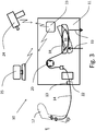
- the mixer 10 comprises a support structure 11 on which all components are supported, i.e. a tray 18 adapted to hold a blood bag 16, a pump 20, a sensor unit 22 and a transceiver unit 23. There are also provide guide and fastening means, schematically indicated at 13, for securing tubing 14, coupled to the blood bag 16, to the mixer 10.
- Fig. 3 the mixer is shown set up for use.
- a needle (not shown) is inserted in the arm 12 of the patient, the needle being connected to a tube 14 conducting blood to the colleting system i.e. the blood mixer 10 holding a blood bag 16.
- the tube 14 is coupled to the collecting bag 16.
- Tube 14 and bag 16 must be sterile and hence the tube 14 preferably should be continuous all the way from the needle to the blood collecting bag 16.
- the blood collecting bag 16 and the tube 14 are delivered as a unit from the manufacturer and in a sterile package that is broken only when it is to be used.
- the blood bag 16 is placed in a tray 18, which as is conventional is coupled to a weighing device for weighing the collected blood so as to indicate when the appropriate amount of blood (normally 450 ml) has been collected.
- the tray 18 can be tilted at least between two positions, as indicated by a broken line contour, for allowing the blood to mix with agents provided in the bag, such as anticoagulants.
- the entire mixer can be tiltable.
- the tilting can implemented with a multi axis system so as to allow tilting in several directions.
- Such cooling can be provided by feeding tempered cooling liquid, such as water, through a channel system in the tray 18.
- tempered cooling liquid such as water
- any cooling system known to the skilled man that provides appropriate cooling is usable.
- the system 10 comprises a pump 20 for ascertaining a controlled flow of blood from the patient to the blood collecting bag 16.
- a preferred pump type is a non-intervening pump, i.e. it performs its pumping action by engaging on the outside of the tubing in a kneading action. Thus, it will not affect sterility of the system.
- Pumps of this type are often referred to as peristaltic pumps, although other terms are used, such as hose pumps or tube pumps, which differ in construction depending i.e. on the pressure levels prevailing in the systems where the pumps are to be installed.
- peripheral pump is taken to mean any pump type that acts on the exterior surface of tubing and displaces portions of the contents inside the tubing in a desired direction so as to feed it forward.
- the present blood mixer is provided with a number of sensors, arranged in a sensor unit schematically indicated at 22.
- the purpose of the sensors is to increase the safety for the blood donor.
- a hemoglobin meter preferably provided, said hemoglobin meter being configured to continuously measure the hemoglobin value of the collected blood. This is suitably achieved by spectrophotometric principles, using a light source of appropriate wavelengths and a detector for the selected wavelength.
- a flow sensor is also preferably provided which is coupled to a regulator configured to regulate the flow of blood by feeding control signals to the pump.
- the purpose is to prevent pressure build-up in the collecting bag, such that the bag is not damaged, or the patient's veins are undamaged.
- the sensors are configured to:
- the reading from the flow sensor can be used to activate a stop function if it is registered that blood inadvertently flow backwards and into the patient again in order to prevent blood from flowing from the bag to the donor.
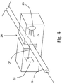
- the sensor unit is schematically illustrated in Fig. 4 . It is preferably based on optical detection and thereby the blood conducting tube 14 itself is used as a cuvette.
- the tube is simply placed in a suitable slot 24 in the sensor unit 22 to intervene in the optical pathway (schematically illustrated with an arrow OP) of the detection system.
- a light source 26 UV, IR or visible depending on what is to be measured transmitting light of the suitable wavelength across the slot 24, passing the tube with blood inside, and a corresponding detector 28. Reflectivity measurements are also possible.
- a pressure sensor for monitoring the pressure inside the tube.
- sensors can be of a piezo-resistive type or any other type that are able to sense the mechanical properties of the tube and correlate them to internal pressure. Any other detection means is of course applicable as long as a reliable flow rate value can be obtained.
- the present apparatus comprises a function that prevents the blood to flow from the collecting bag to the donor. This is essential when the blood mixer is placed at an ergonomic level for the staff monitoring the blood collecting procedure since the elevation of the blood mixer may be higher than the position of the blood donor.
- this stop flow function is suitably implemented in the form of a check valve which may be integrated in the pump.
- the stop flow function will be inherent in that the peristaltic pump type, due its design, will never allow a back flow.
- the pump is configured to exert a kneading action on the blood supply tubing. This is achieved in that the pump comprises at least two kneading elements arranged to alternatingly displace the contents of the tube in the direction towards the bag, over one segment of the tubing each, thereby preventing back flow inside the tubing.
- this kneading and displacing action is performed by rollers often provided on a wheel.
- the tubing is positioned over at least a part of the circumference of the wheel and suitably clamped against the wheel with a suitable holder, suitably along half the circumference, such that at any time at least one roller will press on the tubing and during a revolution of the wheel the roller will displace liquid inside the tubing over a distance corresponding to half the circumference of the wheel.
- the pump 20 itself will also act as a fastening means for securing the tubing to the mixer 10.
- a welder is used for sealing the blood bag by a clamping and melting action to provide a sterile seal.
- the blood mixer may also be provided with a wireless communication device, such as a transceiver, configured to exchange information with a welder 24 and/or a computer 25.
- a wireless communication device such as a transceiver
- the communication can used for recording approved welds of tubing, for traceability purposes, to meet standards of GMP.
- All information recorded in the mixer by the sensors is preferably stored in the unit, and is suitably provided as exportable text files although any kind of data format is of course possible. Furthermore, information is suitably used for controlling continued operation of the system. For example a low Hb value could be triggering a system warning to the operator in the form of a question if operation is to be discontinued.
- the invention provides for a real-time assessment of the quality of the blood to be extracted by continuously measuring the Hb value of the blood.
- the main issue for blood sampling is that the amount of haemoglobin be sufficient in each bag, and preferably the same in all blood bags in a blood bank. Due to the fact that Hb values vary between patients, this is not always the case. The method according to e.g. '553 (mentioned above) will not enable a precise prediction of the amount of haemoglobin in the sampled blood.
- the operator can monitor the accumulation of Hb and terminate the sampling when the exact amount is reached. If the Hb value is high, less blood needs to be collected, and if it is found that the Hb value is too low it is possible to terminate the collection.
- system processor can be programmed to make such decisions automatically.
- the invention in a beneficial manner enables a reduction in process steps in blood collection.
Landscapes
- Health & Medical Sciences (AREA)
- Heart & Thoracic Surgery (AREA)
- Engineering & Computer Science (AREA)
- Animal Behavior & Ethology (AREA)
- Public Health (AREA)
- Biomedical Technology (AREA)
- Hematology (AREA)
- Life Sciences & Earth Sciences (AREA)
- Veterinary Medicine (AREA)
- General Health & Medical Sciences (AREA)
- Anesthesiology (AREA)
- Vascular Medicine (AREA)
- Cardiology (AREA)
- Mechanical Engineering (AREA)
- Pulmonology (AREA)
- External Artificial Organs (AREA)
- Measurement Of The Respiration, Hearing Ability, Form, And Blood Characteristics Of Living Organisms (AREA)
Description
- The present invention relates to blood collection systems in general, and in particular to a mixer for a blood bag in which blood is collected from a donor.
- The task of taking blood from a donor requires many manual operations on the part of the person taking the blood. The blood collecting bags which are normally used, and also the hose connected to the bags and intended to be fitted to a cannula are prefilled with an anticoagulant.
- In order to ascertain adequate mixing of blood and antigoagulant there are provided mixers provided with so called cradles in which the blood bag is placed.
- Various mixers of this kind are known to the art. For instance, mixers are known which include a bag-carrying surface which is caused to rock forwards and backwards with the aid of a crank device which rotates about an axle which extends perpendicularly to the bag-carrying surface. It is also known to provide such mixer with a weight-measuring device which functions to measure the amount of blood that has flowed into the bag. It is also known to provide such mixers with means which function to produce an alarm signal when blood flows too quickly or too slowly into the bag.
- Such a product is described in the granted
US patent 5,147,330 . It relates to a mixer (in the patent the entire device is referred to as a cradle) of the kind which includes a bag-carrying surface which is intended to be rocked reciprocatingly about an axle which extends perpendicularly to said surface, by means of a crank device or the like, said mixer being provided with a weight measuring device which functions to measure the quantity of blood that has flown into the blood bag. The mixer is also provided with a clamping device which functions to squeeze said hose so as to prevent blood from flowing therein, said clamping device being electromagnetically operable, and wherein the mixer is provided with a control circuit which functions to at least control said clamping device. -
US 2012/010553 (A1) (Carlson et al ) a blood collection system that exhibits features such as a support structure, a tray (describe as a "scale", but functions as a tray for a bag), a pump inherently disclosed since there must be some kind of pump in order to extract blood from the donor and a tilting mechanism ("blood agitating system"). - An object of the present apparatus disclosed herein is to provide a blood mixer that will enable an operator to position the mixer at a convenient elevated position higher than the patient, and which ascertains that no blood will flow back from the collecting bag to the patient.
- This object is achieved with a blood mixer as defined in claim 1.
- It comprises a support structure supporting the components of the mixer, a tubing fastening and guiding arrangement, configured to secure a blood collecting tubing in the mixer, a weigh bowl adapted to house a blood collecting bag having a blood supply tube attached thereto, and configured to measure the weight of the collected blood in the blood collecting bag and a pump configured to draw blood from the donor to a blood collecting bag through said tubing. In particular the pump is configured to exert a kneading action on the blood supply tubing by means of at least two kneading elements arranged to alternatingly displace the contents of the tube in the direction towards the bag, over one segment of the tubing each, thereby preventing back flow inside the tubing. There is preferably also provided a cooling arrangement configured to cool the blood in the blood collecting bag.
- The detailed description given hereinafter is to be read with reference to the accompanying drawings which are given by way of illustration only, and thus not to be considered limiting on the present invention, and wherein
-
Fig. 1 illustrates a prior art mixer 1; -
Fig. 2 shows the prior art device ofFig. 1 in a side view; -
Fig. 3 is a schematic illustration of a complete blood collecting system including a mixer; and -
Fig. 4 schematically illustrates a sensor unit. - For the purposes of this application the term "blood mixer" shall be taken to mean an apparatus comprising at least one movable part adapted to receive a blood colleting bag. The movement is preferably a tilting action, either a simple rocking or a multiaxis movement, so as to ascertain proper mixing of the contents of the bag, i.e. collected blood and any agents provide in the bag, such as anticoagulants. The entire apparatus could in principle be moveable/tiltable.
- In particular the part adapted for receiving the blood collecting bag is referred to as a "bowl" or "tray". If a weighing function is integrated in the bowl it is referred to as a "weighing bowl" or "weighing tray".
-
Figs. 1 and 2 schematically illustrates a prior art blood mixer device/system 1 for collecting blood from a patient. This mixer is intended for use in blood donating processes and comprises asurface 2 supported by arod 10, and intended to carry a blood-collecting bag and to be rocked reciprocatingly 6 on an axle 4 which extends perpendicularly to the surface, by means of acrank disc 7 rotatably mounted on ashaft 9 and provided with awheel 5 which runs on the underside of said carrier surface. The mixer is provided with a weight measuring device 8 which functions to measure the quantity of blood that has flowed into the bag. This apparatus does not exhibit any means for preventing back flow of blood. - In
Fig. 3 the present mixer device/system is schematically illustrated. - The
mixer 10 comprises asupport structure 11 on which all components are supported, i.e. atray 18 adapted to hold ablood bag 16, apump 20, asensor unit 22 and atransceiver unit 23. There are also provide guide and fastening means, schematically indicated at 13, for securingtubing 14, coupled to theblood bag 16, to themixer 10. - In
Fig. 3 the mixer is shown set up for use. A needle (not shown) is inserted in thearm 12 of the patient, the needle being connected to atube 14 conducting blood to the colleting system i.e. theblood mixer 10 holding ablood bag 16. Thetube 14 is coupled to thecollecting bag 16.Tube 14 andbag 16 must be sterile and hence thetube 14 preferably should be continuous all the way from the needle to theblood collecting bag 16. Suitably theblood collecting bag 16 and thetube 14 are delivered as a unit from the manufacturer and in a sterile package that is broken only when it is to be used. - The
blood bag 16 is placed in atray 18, which as is conventional is coupled to a weighing device for weighing the collected blood so as to indicate when the appropriate amount of blood (normally 450 ml) has been collected. - The
tray 18 can be tilted at least between two positions, as indicated by a broken line contour, for allowing the blood to mix with agents provided in the bag, such as anticoagulants. Alternatively, the entire mixer can be tiltable. Of course the tilting can implemented with a multi axis system so as to allow tilting in several directions. - A
cooling arrangement 19, schematically indicated by arrows only, is implemented in thetray 18 to reduce the temperature of the collected blood to 22°C to improve the quality of the blood. Such cooling can be provided by feeding tempered cooling liquid, such as water, through a channel system in thetray 18. Of course any cooling system known to the skilled man that provides appropriate cooling is usable. - The
system 10 comprises apump 20 for ascertaining a controlled flow of blood from the patient to theblood collecting bag 16. A preferred pump type is a non-intervening pump, i.e. it performs its pumping action by engaging on the outside of the tubing in a kneading action. Thus, it will not affect sterility of the system. - Pumps of this type are often referred to as peristaltic pumps, although other terms are used, such as hose pumps or tube pumps, which differ in construction depending i.e. on the pressure levels prevailing in the systems where the pumps are to be installed.
- For the purpose of this application the term "peristaltic pump" is taken to mean any pump type that acts on the exterior surface of tubing and displaces portions of the contents inside the tubing in a desired direction so as to feed it forward.
- Furthermore, the present blood mixer is provided with a number of sensors, arranged in a sensor unit schematically indicated at 22. The purpose of the sensors is to increase the safety for the blood donor. To this end there is preferably provided a hemoglobin meter , said hemoglobin meter being configured to continuously measure the hemoglobin value of the collected blood. This is suitably achieved by spectrophotometric principles, using a light source of appropriate wavelengths and a detector for the selected wavelength.
- A flow sensor is also preferably provided which is coupled to a regulator configured to regulate the flow of blood by feeding control signals to the pump. The purpose is to prevent pressure build-up in the collecting bag, such that the bag is not damaged, or the patient's veins are undamaged.
- Thus, the sensors are configured to:
- a) regulate the flow of blood to the collecting
bag 16 to prevent pressure build-up in the collecting bag, by monitoring the flow rate and direction, - b) measure the hemoglobin value in the drawn blood using a Hb meter to ensure quality of the blood.
- If required, the reading from the flow sensor can be used to activate a stop function if it is registered that blood inadvertently flow backwards and into the patient again in order to prevent blood from flowing from the bag to the donor.
- The sensor unit is schematically illustrated in
Fig. 4 . It is preferably based on optical detection and thereby theblood conducting tube 14 itself is used as a cuvette. The tube is simply placed in asuitable slot 24 in thesensor unit 22 to intervene in the optical pathway (schematically illustrated with an arrow OP) of the detection system. Thus, there is provided a light source 26 (UV, IR or visible depending on what is to be measured) transmitting light of the suitable wavelength across theslot 24, passing the tube with blood inside, and a correspondingdetector 28. Reflectivity measurements are also possible. - There can also be provided a pressure sensor for monitoring the pressure inside the tube. Such sensors can be of a piezo-resistive type or any other type that are able to sense the mechanical properties of the tube and correlate them to internal pressure. Any other detection means is of course applicable as long as a reliable flow rate value can be obtained.
- The present apparatus comprises a function that prevents the blood to flow from the collecting bag to the donor. This is essential when the blood mixer is placed at an ergonomic level for the staff monitoring the blood collecting procedure since the elevation of the blood mixer may be higher than the position of the blood donor. In cases where a pump that is integrated in the flow path is used, this stop flow function is suitably implemented in the form of a check valve which may be integrated in the pump.
- In the preferred embodiments of the present blood mixer the stop flow function will be inherent in that the peristaltic pump type, due its design, will never allow a back flow. Namely, the pump is configured to exert a kneading action on the blood supply tubing. This is achieved in that the pump comprises at least two kneading elements arranged to alternatingly displace the contents of the tube in the direction towards the bag, over one segment of the tubing each, thereby preventing back flow inside the tubing.
- In a classic peristaltic pump this kneading and displacing action is performed by rollers often provided on a wheel. The tubing is positioned over at least a part of the circumference of the wheel and suitably clamped against the wheel with a suitable holder, suitably along half the circumference, such that at any time at least one roller will press on the tubing and during a revolution of the wheel the roller will displace liquid inside the tubing over a distance corresponding to half the circumference of the wheel. In this embodiment the
pump 20 itself will also act as a fastening means for securing the tubing to themixer 10. - A welder is used for sealing the blood bag by a clamping and melting action to provide a sterile seal.
- The blood mixer may also be provided with a wireless communication device, such as a transceiver, configured to exchange information with a
welder 24 and/or acomputer 25. The communication can used for recording approved welds of tubing, for traceability purposes, to meet standards of GMP. - All information recorded in the mixer by the sensors is preferably stored in the unit, and is suitably provided as exportable text files although any kind of data format is of course possible. Furthermore, information is suitably used for controlling continued operation of the system. For example a low Hb value could be triggering a system warning to the operator in the form of a question if operation is to be discontinued.
- The invention provides for a real-time assessment of the quality of the blood to be extracted by continuously measuring the Hb value of the blood.
- The main issue for blood sampling is that the amount of haemoglobin be sufficient in each bag, and preferably the same in all blood bags in a blood bank. Due to the fact that Hb values vary between patients, this is not always the case. The method according to e.g. '553 (mentioned above) will not enable a precise prediction of the amount of haemoglobin in the sampled blood.
- By using the apparatus according to the invention, the operator can monitor the accumulation of Hb and terminate the sampling when the exact amount is reached. If the Hb value is high, less blood needs to be collected, and if it is found that the Hb value is too low it is possible to terminate the collection.
- Alternatively, the system processor can be programmed to make such decisions automatically.
- The invention in a beneficial manner enables a reduction in process steps in blood collection.
Claims (6)
- A blood mixer (10) comprising:a support structure (11) supporting the components of the mixer (10) a tray (18) adapted to house a blood collecting bag having a blood tube (14) attached thereto, and configured to measure the weight of the collected blood in the blood collecting bag (10), andfurther comprising a mechanism for causing a repeated tilting of at least the tray (18) in at least one directioncharacterized in thata pump (20) is provided on the support structure and configured to draw blood from the donor to a blood collecting bag through said blood tube (14), and in thatthe pump (20) is configured to exert a kneading action on the blood tube (14) by means of at least two kneading elements arranged to alternatingly displace the contents of the tube in the direction towards the bag, over one segment of the tube each, thereby preventing back flow inside the tube, in thatthe mixer further comprises a sensor unit which comprises a hemoglobin meter, said hemoglobin meter configured to continuously measure the hemoglobin value of the blood flowing in a tubing secured to the mixer, and in thatinformation recorded by the sensors is stored in a suitable format, preferably as text files.
- The blood mixer according to claim 1, wherein the sensor unit comprises a flow detector configured to measure flow rate and flow direction of the blood flowing in said tubing.
- The blood mixer according to claim 2, further comprising a regulator configured to regulate the flow of blood to the collecting bag (10) in response to data from the flow detector.
- The blood mixer according to claim 1, further comprising a wireless communication device (23) configured to exchange information with a welder (24) and/or a computer (25).
- The blood mixer according to any preceding claim, further comprising a cooling arrangement (19) configured to cool blood in the blood collecting bag (16).
- The blood mixer according to any preceding claim, further comprising a tubing fastening and guiding arrangement (13; 20), configured to secure a blood collecting tubing (14) on the mixer (10),
Applications Claiming Priority (2)
| Application Number | Priority Date | Filing Date | Title |
|---|---|---|---|
| SE1551163A SE539282C2 (en) | 2015-09-10 | 2015-09-10 | Blood mixer for use with a blood collecting bag |
| PCT/SE2016/050844 WO2017044040A1 (en) | 2015-09-10 | 2016-09-09 | Blood mixer for a blood collecting bag |
Publications (3)
| Publication Number | Publication Date |
|---|---|
| EP3347069A1 EP3347069A1 (en) | 2018-07-18 |
| EP3347069A4 EP3347069A4 (en) | 2019-05-01 |
| EP3347069B1 true EP3347069B1 (en) | 2020-03-25 |
Family
ID=58240363
Family Applications (1)
| Application Number | Title | Priority Date | Filing Date |
|---|---|---|---|
| EP16844808.2A Active EP3347069B1 (en) | 2015-09-10 | 2016-09-09 | Blood mixer for a blood collecting bag |
Country Status (7)
| Country | Link |
|---|---|
| US (1) | US20180250454A1 (en) |
| EP (1) | EP3347069B1 (en) |
| JP (1) | JP2018532459A (en) |
| KR (1) | KR20180059464A (en) |
| CN (1) | CN108348665A (en) |
| SE (1) | SE539282C2 (en) |
| WO (1) | WO2017044040A1 (en) |
Families Citing this family (5)
| Publication number | Priority date | Publication date | Assignee | Title |
|---|---|---|---|---|
| US11192705B2 (en) * | 2018-07-09 | 2021-12-07 | 1Touch Holdings, Inc. | Smart 1 touch |
| CN110339407A (en) * | 2019-07-22 | 2019-10-18 | 宁波市妇女儿童医院 | A blood collector for postpartum hemorrhage |
| EP4037724B1 (en) * | 2019-09-30 | 2026-01-28 | Fresenius Kabi (Guangzhou) Co., Ltd. | Blood donation system |
| AU2021103236A4 (en) * | 2021-06-04 | 2021-07-29 | Fitbeat Australia Pty Ltd | Exercise band |
| CN116764005A (en) * | 2023-06-25 | 2023-09-19 | 长春理工大学 | Blood sampling device capable of adjusting blood sampling flow rate |
Family Cites Families (29)
| Publication number | Priority date | Publication date | Assignee | Title |
|---|---|---|---|---|
| US2845929A (en) * | 1953-04-30 | 1958-08-05 | Max M Strumia | Apparatus for the collection and cooling of blood |
| US4385630A (en) * | 1980-08-29 | 1983-05-31 | Haemonetics Corporation | Blood donation unit |
| ATE89178T1 (en) * | 1982-12-13 | 1993-05-15 | Mclaughlin William F | BLOOD FRACTIONATION SYSTEM. |
| SE8601891D0 (en) * | 1986-04-24 | 1986-04-24 | Svante Jonsson | PLASMA SWITCH TREATMENT AND TROMBOCYTING MACHINE |
| FR2606639B1 (en) * | 1986-11-19 | 1994-04-15 | Tiyoda Seisakusho Kk | APPARATUS AND METHOD FOR COLLECTING CONSTANT QUANTITIES OF BLOOD FROM INDIVIDUAL DONORS |
| SE8902014L (en) * | 1989-06-02 | 1990-12-03 | Gambro Ab | AUTOTRANSFUSION SYSTEM FOR COLLECTION, TREATMENT AND TRANSFER OF A PATIENT'S BLOOD |
| SE469261B (en) * | 1989-10-18 | 1993-06-14 | Ljungberg & Koegel Ab | BLOOD ROCK |
| US5385539A (en) * | 1992-06-30 | 1995-01-31 | Advanced Haemotechnologies | Apparatus for monitoring hematocrit levels of blood |
| CA2140141A1 (en) * | 1992-07-13 | 1994-01-20 | Pall Corporation | Automated system and method for processing biological fluid |
| WO1994019031A1 (en) * | 1993-02-18 | 1994-09-01 | Baxter International Inc. | Apheresis system incorporating alternative site for anticoagulant addition |
| US6527957B1 (en) * | 1995-08-09 | 2003-03-04 | Baxter International Inc. | Methods for separating, collecting and storing red blood cells |
| US5658271A (en) * | 1996-02-08 | 1997-08-19 | Loubser; Paul G. | Closed circuit autologous sequestration reservoir system |
| US5955672A (en) * | 1997-04-29 | 1999-09-21 | Medtronic, Inc. | Ultrasonic blood volume measurement in soft-shell venous reservoir |
| US6113554A (en) * | 1998-10-16 | 2000-09-05 | Haemonetics Corporation | Automatic whole blood collection system |
| WO2000023140A1 (en) * | 1998-10-16 | 2000-04-27 | Mission Medical, Inc. | Blood processing system |
| CA2370758A1 (en) * | 2000-03-01 | 2001-09-07 | Gambro, Inc. | Extracorporeal blood processing information management system |
| FR2808693B1 (en) * | 2000-05-12 | 2002-10-25 | Maco Pharma Sa | TAKING DEVICE WITH TUBES OF DIFFERENT SECTION |
| CN2438454Y (en) * | 2000-07-07 | 2001-07-11 | 山西人康医疗器械有限公司 | Multifunction blood therapeutical instrument |
| EP1476208B1 (en) * | 2002-02-01 | 2011-10-05 | CaridianBCT, Inc. | Whole blood collection and processing system |
| JP4220199B2 (en) * | 2002-08-23 | 2009-02-04 | 川澄化学工業株式会社 | Blood collection apparatus and blood collection system |
| US7608043B1 (en) * | 2002-10-18 | 2009-10-27 | Global Monitors, Inc. | Optical and ultrasound probe for monitoring blood volume changes |
| JP4540949B2 (en) * | 2003-07-30 | 2010-09-08 | ヘモネティクス・コーポレーション | Apheresis equipment |
| US9173988B2 (en) * | 2010-11-17 | 2015-11-03 | Fresenius Medical Care Holdings, Inc. | Sensor clip assembly for an optical monitoring system |
| JP5244896B2 (en) * | 2010-12-03 | 2013-07-24 | Junken Medical株式会社 | Device for blood transfusion / infusion or blood purification and method for detecting defective suction of pump in the device |
| US9033948B2 (en) * | 2011-04-19 | 2015-05-19 | Fenwel, Inc. | Single collection bag blood collection system, method and apparatus |
| WO2014007742A1 (en) * | 2012-07-05 | 2014-01-09 | Stroemberg Lennart | Blood collection system and method |
| GB201313137D0 (en) * | 2013-07-23 | 2013-09-04 | Brightwake Ltd | Apparatus for blood concentration |
| US9308306B2 (en) * | 2014-02-24 | 2016-04-12 | Fresenius Medical Care Holdings, Inc. | Self calibrating blood chamber |
| CN104667362A (en) * | 2015-03-24 | 2015-06-03 | 傅敏 | Full-automatic whole blood collection separator and matched disposable collecting-separating device |
-
2015
- 2015-09-10 SE SE1551163A patent/SE539282C2/en unknown
-
2016
- 2016-09-09 US US15/759,269 patent/US20180250454A1/en not_active Abandoned
- 2016-09-09 JP JP2018512405A patent/JP2018532459A/en active Pending
- 2016-09-09 CN CN201680063771.2A patent/CN108348665A/en active Pending
- 2016-09-09 EP EP16844808.2A patent/EP3347069B1/en active Active
- 2016-09-09 KR KR1020187010022A patent/KR20180059464A/en not_active Ceased
- 2016-09-09 WO PCT/SE2016/050844 patent/WO2017044040A1/en not_active Ceased
Non-Patent Citations (1)
| Title |
|---|
| None * |
Also Published As
| Publication number | Publication date |
|---|---|
| SE1551163A1 (en) | 2017-03-11 |
| CN108348665A (en) | 2018-07-31 |
| JP2018532459A (en) | 2018-11-08 |
| EP3347069A1 (en) | 2018-07-18 |
| EP3347069A4 (en) | 2019-05-01 |
| US20180250454A1 (en) | 2018-09-06 |
| WO2017044040A1 (en) | 2017-03-16 |
| SE539282C2 (en) | 2017-06-13 |
| KR20180059464A (en) | 2018-06-04 |
Similar Documents
| Publication | Publication Date | Title |
|---|---|---|
| US20180250454A1 (en) | Blood mixer for a blood collecting bag | |
| US8394077B2 (en) | Controlled delivery of substances system and method | |
| EP3035054B1 (en) | Systems and methods for determining free plasma hemoglobin | |
| EP3110474B1 (en) | Infusion system and method which utilizes dual wavelength optical air-in-line detection | |
| US7879000B2 (en) | Method, system and machine for collecting a biological fluid to which a selected ratio of solution is added | |
| CN105848694B (en) | Fluid Control Systems and Disposable Components | |
| US9482563B2 (en) | Real time measurements of fluid volume and flow rate using two pressure transducers | |
| JP2007516805A (en) | Improvement of drug administration safety for secondary injection | |
| KR920704115A (en) | Automatic liquid sampling and inspection device and method | |
| EP3952940B1 (en) | Blood collection device | |
| US9956141B2 (en) | Automatic fluid container switching in a blood processing system | |
| JP2008515483A (en) | Blood monitoring system | |
| EP1909866B1 (en) | A machine for extracorporeal blood treatment | |
| JP2024520640A (en) | Automatically Adjustable IV Stand | |
| EP3266481A1 (en) | System and method for identifying a fill volume of a fluid chamber | |
| KR20160149927A (en) | Device for automatically adjusting medication-speed of infusion solution | |
| US20120285545A1 (en) | Monitoring And Detecting Empty Fluid Containers In A Blood Processing System | |
| EP3474916B1 (en) | Body drainage apparatus | |
| CA2748952C (en) | Device for measuring at least one parameter of an arterial blood sample | |
| JP2005534582A (en) | Filling device for capsules, in particular drug capsules | |
| CN208677932U (en) | A kind of dispensation apparatus of ampoule bottle | |
| JP2015158472A (en) | Liquid circuit panel unit mount structure | |
| US20130083331A1 (en) | System for monitoring the position of a tube's distal end relative to a blood vessel | |
| TW201519922A (en) | Medical solution delivery device and medical solution delivery monitoring device |
Legal Events
| Date | Code | Title | Description |
|---|---|---|---|
| STAA | Information on the status of an ep patent application or granted ep patent |
Free format text: STATUS: THE INTERNATIONAL PUBLICATION HAS BEEN MADE |
|
| PUAI | Public reference made under article 153(3) epc to a published international application that has entered the european phase |
Free format text: ORIGINAL CODE: 0009012 |
|
| STAA | Information on the status of an ep patent application or granted ep patent |
Free format text: STATUS: REQUEST FOR EXAMINATION WAS MADE |
|
| 17P | Request for examination filed |
Effective date: 20180328 |
|
| AK | Designated contracting states |
Kind code of ref document: A1 Designated state(s): AL AT BE BG CH CY CZ DE DK EE ES FI FR GB GR HR HU IE IS IT LI LT LU LV MC MK MT NL NO PL PT RO RS SE SI SK SM TR |
|
| AX | Request for extension of the european patent |
Extension state: BA ME |
|
| DAV | Request for validation of the european patent (deleted) | ||
| DAX | Request for extension of the european patent (deleted) | ||
| A4 | Supplementary search report drawn up and despatched |
Effective date: 20190328 |
|
| RIC1 | Information provided on ipc code assigned before grant |
Ipc: A61M 1/10 20060101ALI20190322BHEP Ipc: A61M 1/02 20060101AFI20190322BHEP |
|
| GRAP | Despatch of communication of intention to grant a patent |
Free format text: ORIGINAL CODE: EPIDOSNIGR1 |
|
| STAA | Information on the status of an ep patent application or granted ep patent |
Free format text: STATUS: GRANT OF PATENT IS INTENDED |
|
| INTG | Intention to grant announced |
Effective date: 20191111 |
|
| GRAS | Grant fee paid |
Free format text: ORIGINAL CODE: EPIDOSNIGR3 |
|
| GRAA | (expected) grant |
Free format text: ORIGINAL CODE: 0009210 |
|
| STAA | Information on the status of an ep patent application or granted ep patent |
Free format text: STATUS: THE PATENT HAS BEEN GRANTED |
|
| AK | Designated contracting states |
Kind code of ref document: B1 Designated state(s): AL AT BE BG CH CY CZ DE DK EE ES FI FR GB GR HR HU IE IS IT LI LT LU LV MC MK MT NL NO PL PT RO RS SE SI SK SM TR |
|
| REG | Reference to a national code |
Ref country code: GB Ref legal event code: FG4D |
|
| REG | Reference to a national code |
Ref country code: AT Ref legal event code: REF Ref document number: 1247821 Country of ref document: AT Kind code of ref document: T Effective date: 20200415 Ref country code: IE Ref legal event code: FG4D |
|
| REG | Reference to a national code |
Ref country code: DE Ref legal event code: R096 Ref document number: 602016032729 Country of ref document: DE |
|
| PG25 | Lapsed in a contracting state [announced via postgrant information from national office to epo] |
Ref country code: RS Free format text: LAPSE BECAUSE OF FAILURE TO SUBMIT A TRANSLATION OF THE DESCRIPTION OR TO PAY THE FEE WITHIN THE PRESCRIBED TIME-LIMIT Effective date: 20200325 Ref country code: NO Free format text: LAPSE BECAUSE OF FAILURE TO SUBMIT A TRANSLATION OF THE DESCRIPTION OR TO PAY THE FEE WITHIN THE PRESCRIBED TIME-LIMIT Effective date: 20200625 Ref country code: FI Free format text: LAPSE BECAUSE OF FAILURE TO SUBMIT A TRANSLATION OF THE DESCRIPTION OR TO PAY THE FEE WITHIN THE PRESCRIBED TIME-LIMIT Effective date: 20200325 |
|
| PG25 | Lapsed in a contracting state [announced via postgrant information from national office to epo] |
Ref country code: LV Free format text: LAPSE BECAUSE OF FAILURE TO SUBMIT A TRANSLATION OF THE DESCRIPTION OR TO PAY THE FEE WITHIN THE PRESCRIBED TIME-LIMIT Effective date: 20200325 Ref country code: SE Free format text: LAPSE BECAUSE OF FAILURE TO SUBMIT A TRANSLATION OF THE DESCRIPTION OR TO PAY THE FEE WITHIN THE PRESCRIBED TIME-LIMIT Effective date: 20200325 Ref country code: GR Free format text: LAPSE BECAUSE OF FAILURE TO SUBMIT A TRANSLATION OF THE DESCRIPTION OR TO PAY THE FEE WITHIN THE PRESCRIBED TIME-LIMIT Effective date: 20200626 Ref country code: HR Free format text: LAPSE BECAUSE OF FAILURE TO SUBMIT A TRANSLATION OF THE DESCRIPTION OR TO PAY THE FEE WITHIN THE PRESCRIBED TIME-LIMIT Effective date: 20200325 Ref country code: BG Free format text: LAPSE BECAUSE OF FAILURE TO SUBMIT A TRANSLATION OF THE DESCRIPTION OR TO PAY THE FEE WITHIN THE PRESCRIBED TIME-LIMIT Effective date: 20200625 |
|
| REG | Reference to a national code |
Ref country code: NL Ref legal event code: MP Effective date: 20200325 |
|
| REG | Reference to a national code |
Ref country code: LT Ref legal event code: MG4D |
|
| PG25 | Lapsed in a contracting state [announced via postgrant information from national office to epo] |
Ref country code: NL Free format text: LAPSE BECAUSE OF FAILURE TO SUBMIT A TRANSLATION OF THE DESCRIPTION OR TO PAY THE FEE WITHIN THE PRESCRIBED TIME-LIMIT Effective date: 20200325 |
|
| PG25 | Lapsed in a contracting state [announced via postgrant information from national office to epo] |
Ref country code: SK Free format text: LAPSE BECAUSE OF FAILURE TO SUBMIT A TRANSLATION OF THE DESCRIPTION OR TO PAY THE FEE WITHIN THE PRESCRIBED TIME-LIMIT Effective date: 20200325 Ref country code: SM Free format text: LAPSE BECAUSE OF FAILURE TO SUBMIT A TRANSLATION OF THE DESCRIPTION OR TO PAY THE FEE WITHIN THE PRESCRIBED TIME-LIMIT Effective date: 20200325 Ref country code: EE Free format text: LAPSE BECAUSE OF FAILURE TO SUBMIT A TRANSLATION OF THE DESCRIPTION OR TO PAY THE FEE WITHIN THE PRESCRIBED TIME-LIMIT Effective date: 20200325 Ref country code: LT Free format text: LAPSE BECAUSE OF FAILURE TO SUBMIT A TRANSLATION OF THE DESCRIPTION OR TO PAY THE FEE WITHIN THE PRESCRIBED TIME-LIMIT Effective date: 20200325 Ref country code: PT Free format text: LAPSE BECAUSE OF FAILURE TO SUBMIT A TRANSLATION OF THE DESCRIPTION OR TO PAY THE FEE WITHIN THE PRESCRIBED TIME-LIMIT Effective date: 20200818 Ref country code: RO Free format text: LAPSE BECAUSE OF FAILURE TO SUBMIT A TRANSLATION OF THE DESCRIPTION OR TO PAY THE FEE WITHIN THE PRESCRIBED TIME-LIMIT Effective date: 20200325 Ref country code: CZ Free format text: LAPSE BECAUSE OF FAILURE TO SUBMIT A TRANSLATION OF THE DESCRIPTION OR TO PAY THE FEE WITHIN THE PRESCRIBED TIME-LIMIT Effective date: 20200325 Ref country code: IS Free format text: LAPSE BECAUSE OF FAILURE TO SUBMIT A TRANSLATION OF THE DESCRIPTION OR TO PAY THE FEE WITHIN THE PRESCRIBED TIME-LIMIT Effective date: 20200725 |
|
| REG | Reference to a national code |
Ref country code: AT Ref legal event code: MK05 Ref document number: 1247821 Country of ref document: AT Kind code of ref document: T Effective date: 20200325 |
|
| REG | Reference to a national code |
Ref country code: DE Ref legal event code: R097 Ref document number: 602016032729 Country of ref document: DE |
|
| PG25 | Lapsed in a contracting state [announced via postgrant information from national office to epo] |
Ref country code: AT Free format text: LAPSE BECAUSE OF FAILURE TO SUBMIT A TRANSLATION OF THE DESCRIPTION OR TO PAY THE FEE WITHIN THE PRESCRIBED TIME-LIMIT Effective date: 20200325 Ref country code: ES Free format text: LAPSE BECAUSE OF FAILURE TO SUBMIT A TRANSLATION OF THE DESCRIPTION OR TO PAY THE FEE WITHIN THE PRESCRIBED TIME-LIMIT Effective date: 20200325 Ref country code: IT Free format text: LAPSE BECAUSE OF FAILURE TO SUBMIT A TRANSLATION OF THE DESCRIPTION OR TO PAY THE FEE WITHIN THE PRESCRIBED TIME-LIMIT Effective date: 20200325 Ref country code: DK Free format text: LAPSE BECAUSE OF FAILURE TO SUBMIT A TRANSLATION OF THE DESCRIPTION OR TO PAY THE FEE WITHIN THE PRESCRIBED TIME-LIMIT Effective date: 20200325 |
|
| PLBE | No opposition filed within time limit |
Free format text: ORIGINAL CODE: 0009261 |
|
| STAA | Information on the status of an ep patent application or granted ep patent |
Free format text: STATUS: NO OPPOSITION FILED WITHIN TIME LIMIT |
|
| PG25 | Lapsed in a contracting state [announced via postgrant information from national office to epo] |
Ref country code: PL Free format text: LAPSE BECAUSE OF FAILURE TO SUBMIT A TRANSLATION OF THE DESCRIPTION OR TO PAY THE FEE WITHIN THE PRESCRIBED TIME-LIMIT Effective date: 20200325 |
|
| 26N | No opposition filed |
Effective date: 20210112 |
|
| REG | Reference to a national code |
Ref country code: CH Ref legal event code: PL |
|
| PG25 | Lapsed in a contracting state [announced via postgrant information from national office to epo] |
Ref country code: SI Free format text: LAPSE BECAUSE OF FAILURE TO SUBMIT A TRANSLATION OF THE DESCRIPTION OR TO PAY THE FEE WITHIN THE PRESCRIBED TIME-LIMIT Effective date: 20200325 |
|
| REG | Reference to a national code |
Ref country code: BE Ref legal event code: MM Effective date: 20200930 |
|
| PG25 | Lapsed in a contracting state [announced via postgrant information from national office to epo] |
Ref country code: LU Free format text: LAPSE BECAUSE OF NON-PAYMENT OF DUE FEES Effective date: 20200909 |
|
| PG25 | Lapsed in a contracting state [announced via postgrant information from national office to epo] |
Ref country code: BE Free format text: LAPSE BECAUSE OF NON-PAYMENT OF DUE FEES Effective date: 20200930 Ref country code: CH Free format text: LAPSE BECAUSE OF NON-PAYMENT OF DUE FEES Effective date: 20200930 Ref country code: LI Free format text: LAPSE BECAUSE OF NON-PAYMENT OF DUE FEES Effective date: 20200930 Ref country code: IE Free format text: LAPSE BECAUSE OF NON-PAYMENT OF DUE FEES Effective date: 20200909 |
|
| PG25 | Lapsed in a contracting state [announced via postgrant information from national office to epo] |
Ref country code: TR Free format text: LAPSE BECAUSE OF FAILURE TO SUBMIT A TRANSLATION OF THE DESCRIPTION OR TO PAY THE FEE WITHIN THE PRESCRIBED TIME-LIMIT Effective date: 20200325 Ref country code: MT Free format text: LAPSE BECAUSE OF FAILURE TO SUBMIT A TRANSLATION OF THE DESCRIPTION OR TO PAY THE FEE WITHIN THE PRESCRIBED TIME-LIMIT Effective date: 20200325 Ref country code: CY Free format text: LAPSE BECAUSE OF FAILURE TO SUBMIT A TRANSLATION OF THE DESCRIPTION OR TO PAY THE FEE WITHIN THE PRESCRIBED TIME-LIMIT Effective date: 20200325 |
|
| PG25 | Lapsed in a contracting state [announced via postgrant information from national office to epo] |
Ref country code: MK Free format text: LAPSE BECAUSE OF FAILURE TO SUBMIT A TRANSLATION OF THE DESCRIPTION OR TO PAY THE FEE WITHIN THE PRESCRIBED TIME-LIMIT Effective date: 20200325 Ref country code: MC Free format text: LAPSE BECAUSE OF FAILURE TO SUBMIT A TRANSLATION OF THE DESCRIPTION OR TO PAY THE FEE WITHIN THE PRESCRIBED TIME-LIMIT Effective date: 20200325 Ref country code: AL Free format text: LAPSE BECAUSE OF FAILURE TO SUBMIT A TRANSLATION OF THE DESCRIPTION OR TO PAY THE FEE WITHIN THE PRESCRIBED TIME-LIMIT Effective date: 20200325 |
|
| P01 | Opt-out of the competence of the unified patent court (upc) registered |
Effective date: 20230505 |
|
| PGFP | Annual fee paid to national office [announced via postgrant information from national office to epo] |
Ref country code: DE Payment date: 20250917 Year of fee payment: 10 |
|
| PGFP | Annual fee paid to national office [announced via postgrant information from national office to epo] |
Ref country code: GB Payment date: 20250916 Year of fee payment: 10 |
|
| PGFP | Annual fee paid to national office [announced via postgrant information from national office to epo] |
Ref country code: FR Payment date: 20250917 Year of fee payment: 10 |