EP3346802A1 - Apparatus for operating one or more lighting devices - Google Patents
Apparatus for operating one or more lighting devices Download PDFInfo
- Publication number
- EP3346802A1 EP3346802A1 EP18150018.2A EP18150018A EP3346802A1 EP 3346802 A1 EP3346802 A1 EP 3346802A1 EP 18150018 A EP18150018 A EP 18150018A EP 3346802 A1 EP3346802 A1 EP 3346802A1
- Authority
- EP
- European Patent Office
- Prior art keywords
- transformer
- operating apparatus
- charger
- lighting devices
- electrical energy
- Prior art date
- Legal status (The legal status is an assumption and is not a legal conclusion. Google has not performed a legal analysis and makes no representation as to the accuracy of the status listed.)
- Granted
Links
Images


Classifications
-
- H—ELECTRICITY
- H05—ELECTRIC TECHNIQUES NOT OTHERWISE PROVIDED FOR
- H05B—ELECTRIC HEATING; ELECTRIC LIGHT SOURCES NOT OTHERWISE PROVIDED FOR; CIRCUIT ARRANGEMENTS FOR ELECTRIC LIGHT SOURCES, IN GENERAL
- H05B45/00—Circuit arrangements for operating light-emitting diodes [LED]
- H05B45/30—Driver circuits
- H05B45/37—Converter circuits
- H05B45/3725—Switched mode power supply [SMPS]
- H05B45/385—Switched mode power supply [SMPS] using flyback topology
-
- H—ELECTRICITY
- H05—ELECTRIC TECHNIQUES NOT OTHERWISE PROVIDED FOR
- H05B—ELECTRIC HEATING; ELECTRIC LIGHT SOURCES NOT OTHERWISE PROVIDED FOR; CIRCUIT ARRANGEMENTS FOR ELECTRIC LIGHT SOURCES, IN GENERAL
- H05B45/00—Circuit arrangements for operating light-emitting diodes [LED]
- H05B45/30—Driver circuits
- H05B45/37—Converter circuits
-
- H—ELECTRICITY
- H02—GENERATION; CONVERSION OR DISTRIBUTION OF ELECTRIC POWER
- H02J—ELECTRIC POWER NETWORKS; CIRCUIT ARRANGEMENTS OR SYSTEMS FOR SUPPLYING OR DISTRIBUTING ELECTRIC POWER; SYSTEMS FOR STORING ELECTRIC ENERGY
- H02J9/00—Circuit arrangements for emergency or stand-by power supply, e.g. for emergency lighting
- H02J9/04—Circuit arrangements for emergency or stand-by power supply, e.g. for emergency lighting in which the distribution system is disconnected from the normal source and connected to a standby source
-
- H—ELECTRICITY
- H02—GENERATION; CONVERSION OR DISTRIBUTION OF ELECTRIC POWER
- H02J—ELECTRIC POWER NETWORKS; CIRCUIT ARRANGEMENTS OR SYSTEMS FOR SUPPLYING OR DISTRIBUTING ELECTRIC POWER; SYSTEMS FOR STORING ELECTRIC ENERGY
- H02J9/00—Circuit arrangements for emergency or stand-by power supply, e.g. for emergency lighting
- H02J9/04—Circuit arrangements for emergency or stand-by power supply, e.g. for emergency lighting in which the distribution system is disconnected from the normal source and connected to a standby source
- H02J9/06—Circuit arrangements for emergency or stand-by power supply, e.g. for emergency lighting in which the distribution system is disconnected from the normal source and connected to a standby source with automatic change-over, e.g. UPS systems
- H02J9/062—Circuit arrangements for emergency or stand-by power supply, e.g. for emergency lighting in which the distribution system is disconnected from the normal source and connected to a standby source with automatic change-over, e.g. UPS systems for AC powered loads
- H02J9/065—Circuit arrangements for emergency or stand-by power supply, e.g. for emergency lighting in which the distribution system is disconnected from the normal source and connected to a standby source with automatic change-over, e.g. UPS systems for AC powered loads for lighting purposes
-
- H—ELECTRICITY
- H05—ELECTRIC TECHNIQUES NOT OTHERWISE PROVIDED FOR
- H05B—ELECTRIC HEATING; ELECTRIC LIGHT SOURCES NOT OTHERWISE PROVIDED FOR; CIRCUIT ARRANGEMENTS FOR ELECTRIC LIGHT SOURCES, IN GENERAL
- H05B47/00—Circuit arrangements for operating light sources in general, i.e. where the type of light source is not relevant
- H05B47/10—Controlling the light source
- H05B47/17—Operational modes, e.g. switching from manual to automatic mode or prohibiting specific operations
- H05B47/172—Emergency operational modes
Definitions
- the present invention relates to an apparatus for operating one or more lighting devices.
- apparatuses arranged to operate one or more lighting devices such as light emitting diodes (LEDs), operate with an existing lighting device driver to add emergency capability.
- An apparatus, arranged to operate the lighting device(s) monitors the mains voltage/current/power/energy, supplied by an external energy or power source respectively and provided further to the lighting device(s), and operates a relay that switches the lighting device driver off during emergency.
- Such emergency case occurs, for example, when the mains voltage/current/power/energy is no longer available or when the supply of the mains voltage/current/power/energy malfunctions.
- the apparatus, arranged to operate lighting device(s) does not obtain the electrical energy (i.e. current, voltage) from the external energy source but from an energy storage device such as battery and provides the electrical energy, obtained from the energy storage device (e.g., battery), to the one or more lighting devices.
- separate components are utilized for providing to the one or more lighting devices the electrical energy: one component arranged to provide to the one or more lighting devices the electrical energy supplied by an external energy source and a further component arranged to provide to the one or more lighting devices the electrical energy supplied by an energy storage device (e.g., a battery).
- an energy storage device e.g., a battery
- an apparatus for operating one or more lighting devices is required that can be manufactured in a cost-effective way, that has a simple structure, and that is small, i.e. does not require a lot of space when installed and used.
- the object of the present invention is to enable an improved operating apparatus arranged to operate one or more lighting devices.
- a provision of an operating apparatus is desired that can be manufactured in a cost-effective way, that has a simple and effective structure, and/or that is small, i.e. does not require a lot of space when installed and used.
- the present invention is based on the idea to use, in an operating apparatus that operates one or more lighting devices such as LEDs, only one transformer for both a charger, which charges an energy storage device for an emergency case, and a lighting device driver, which provides to one or more lighting devices electrical energy (current, voltage) that is supplied by an external electrical energy source in a normal operation case of the operating apparatus.
- the transformer is a part of a converter, arranged to convert electrical energy from one voltage level to another.
- the transformer is a part of a flyback converter, i.e. the operating apparatus is or comprises a flyback converter.
- an operating apparatus is provided that is arranged to operate one or more lighting devices, wherein the operating apparatus comprises: a transformer comprising a primary side and a secondary side, wherein electrical energy is transferred from the primary side to the secondary side of the transformer for operating the one or more lighting devices; a charger arranged on the secondary side of the transformer and configured to charge an energy storage device with the electrical energy, transferred from the primary side to the secondary side of the transformer; a lighting device driver arranged on the secondary side of the transformer and configured to deliver to the one or more lighting devices the electrical energy, transferred from the primary side to the secondary side of the transformer.
- the charger and the lighting device driver are connected to the secondary side of the transformer.
- the primary side of the transformer comprises a primary winding and the secondary side of the transformer comprises at least one secondary winding; and the charger and the lighting device driver are connected to the at least one secondary winding of the transformer.
- the secondary side of the transformer comprises at least two secondary windings; and the charger and the lighting device driver are connected to different secondary windings of the transformer.
- the secondary winding is a taped secondary winding; the charger and the lighting device driver are connected to the taped secondary winding; and the charger and/or the lighting device driver are/is connected to a respective point of the taped secondary winding.
- the electrical energy, transferred from the primary side to the secondary side of the transformer, is selectively and/or alternately provided to the charger or to the lighting device driver.
- the charger and the lighting device driver are operated selectively and/or alternately.
- the charger comprises a charger switch configured to switch on or off the transfer of the electrical energy to the charger.
- the lighting device driver comprises: a main capacitor, which is configured to transfer electrical energy to the one or more lighting devices when the electrical energy flows through the primary side of the transformer and is stored in the transformer; and a main capacitor isolating switch, which is configured to isolate the main capacitor from the charger when the charger charges the energy storage device with the electrical energy, transferred from the primary side to the secondary side of the transformer.
- the operating apparatus if a lighting device voltage, flowing through the one or more lighting devices, is greater than an energy storage device voltage, the operating apparatus is configured to connect the one or more lighting devices to a negative terminal of the energy storage device; and if the lighting device voltage, flowing through the one or more lighting devices, is smaller than the energy storage device voltage, the operating apparatus is configured to connect the one or more lighting devices to a positive terminal of the energy storage device.
- the operating apparatus comprises an isolation barrier between the one or more lighting devices and the energy storage device.
- the operating apparatus is a flyback converter and the transformer is a transformer of the flyback converter.
- the operating apparatus comprises one or more outputs, to which the one or more lighting devices are directly or indirectly connectable and which are configured to provide the electrical energy to the one or more lighting devices.
- the operating apparatus is operated in a normal operation mode and in an emergency operation mode; wherein, in the normal operation mode, the electrical energy is provided to the one or more lighting devices via the lighting device driver; and wherein, in the emergency operation mode, the electrical energy is provided to the one or more lighting devices via the energy storage device.
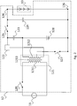
- Fig. 1 shows an operating apparatus 12 according to an embodiment of the present invention.
- the operating apparatus 12 comprises a transformer 121, a charger 127, 128, and a lighting device driver 122, 125, 123, 124. Further, the apparatus 12 comprises outputs 126 that are connectable to one or more lighting devices 13 for providing electrical energy (e.g., current, voltage) to the one or more lighting devices 13.
- the charger switch 127 may be formed by a MOSFET and may comprise an integrated body diode. The charger switch may be formed by a bipolar transistor or an IGBT. There may be an antiparallel diode in parallel to the charger switch 127.
- connection of the operating apparatus 12 to the one or more lighting devices 13 may be a direct connection or an indirect connection. In the case of a direct connection, no further components are present between the operating apparatus 12 and the one or more lighting devices 13. In the case of an indirect connection, further components are present between the operating apparatus 12 and the one or more lighting devices 13.
- the operating apparatus 12 is connected to an external electrical energy source 11, i.e. an external energy source 11. Also here, the connection between the operating apparatus 12 and the external electrical energy source 11 may be a direct or indirect connection.
- the operating apparatus 12 obtains, in a normal operation mode of the operating apparatus 12, the electrical energy (e.g., current, voltage) from the external energy source 11 and provides the obtained electrical energy to the one or more lighting devices 13.
- the electrical energy e.g., current, voltage
- the provision of the electrical energy to the one or more lighting devices 13 is done via the output (s) 126 of the operating apparatus.
- the operating apparatus 12 comprises a transformer 121, via which the electrical energy obtained from the external energy source 11 is provided to the one or more lighting devices 13.
- the transformer 121 comprises a primary side 1211 and a secondary side 1212. According to the present embodiment, the primary side 1211 and the secondary side 1212 are galvanically isolated 1213. The electrical energy obtained from the external energy source 11 is transferred from the primary side 1211 to the secondary side 1212 of the transformer 121.
- the primary side 1211 of the transformer 121 comprises at least one primary winding 1211
- the secondary side 1212 of the transformer 121 comprises at least one secondary winding 1212.
- the electrical energy (e.g., voltage, current) is transferred via the primary side 1211 (i.e. via the primary winding 1211) and stored in the transformer 121.
- the storage of the electrical energy is done by the galvanic isolation 1213.
- the electrical energy, stored via the galvanic isolation is supplied to the secondary side 1212 (i.e. to the secondary winding 1212) of the transformer.
- the operating apparatus 12 is a flyback converter
- the transformer 121 is a transformer of the flyback converter 12.
- the operating apparatus or flyback converter 12 respectively is divided into a primary side and a secondary side.
- the primary side of the operating apparatus or flyback converter 12 respectively comprises components of the operating apparatus or flyback converter 12 respectively that are arranged before the transformer 121. Additionally, the primary side of the operating apparatus or flyback converter 12 respectively comprises the primary side 1211 of the transformer 121.
- the secondary side of the operating apparatus or flyback converter 12 respectively comprises components of the operating apparatus or flyback converter 12 respectively that are arranged after the transformer 121. Additionally, the secondary side of the operating apparatus or flyback converter 12 respectively comprises the secondary side 1212 of the transformer 121.
- the operating apparatus or flyback converter 12 respectively comprises on its primary side a switch 120.
- the switch 120 When the switch 120 is closed (i.e. ON and conductive), the transformer 121 and, particularly, the primary side 1211 of the transformer 121 is connected to the external energy source 11.
- the electrical energy is supplied from the external energy source 11 to the transformer 121 and, particularly, the primary side 1211 of the transformer 121.
- the energy (i.e. current, voltage) and magnetic flux in the transformer 121 increases, storing energy in the transformer 121, particularly, in the galvanic isolation 1213 of the transformer 121.
- the energy i.e.
- the switch 120 of the primary side of the operating device or flyback converter 12 When the switch 120 of the primary side of the operating device or flyback converter 12 is opened (i.e. is OFF and non-conductive), the energy transfer from the external energy source 11 is stopped. The energy (current, voltage) on the primary side 1211 of the transformer 121 and the magnetic flux drops. The energy (current, voltage) on the secondary side 1212 becomes positive. Thus, the diode 122 is forward biased (i.e. is not blocked), or, in case that instead the diode a switch 122 is used, the switch 122 is closed (i.e. is ON and non-conductive). In this way, the electrical energy is allowed to flow from the transformer 121 to the one or more lighting devices 13 (e.g., LEDs).
- the one or more lighting devices 13 e.g., LEDs
- the electrical energy flows to the one or more lighting devices 13
- electrical energy is stored in a main capacitor 124 of the secondary side of the operating apparatus or flyback converter 12 respectively.
- the energy, stored in the main capacitor 124 is provided to the one or more lighting devices 13 when the switch 120 is closed (i.e. is ON and conductive) and, thus, when no electrical energy flows from the transformer 121 to the one or more lighting devices 13.
- the above described ON- and OFF-phases of the switch 120 of the primary side of the operating apparatus or flyback converter 12 respectively are repeated alternately.
- the switching of the switch 120 can be controlled by a controlling entity.
- the controlling entity is not shown in Fig. 1 . However, this way of controlling the switch 120 is well known and is, therefore, not described in more detail herein.
- the operating apparatus or flyback converter 12 respectively comprises a lighting device driver arranged on the secondary side of the transformer 121 and, thus, also on the secondary side of the operating apparatus or flyback converter 12 respectively.
- the lighting device driver is configured to deliver to the one or more lighting devices 13 the electrical energy (current, voltage), transferred from the primary side 1211 to the secondary side 1212 of the transformer 121, i.e. from the primary side of the operating apparatus or flyback converter 12 to the secondary side of the operating apparatus or flyback converter 12.
- the lighting device driver provides to the one or more lighting devices electrical energy supplied by the external energy source 11.
- the lighting device driver comprises according to the present embodiment at least the diode or switch 122 and the main capacitor 124. Additionally, the lighting device driver comprises according to the present embodiment at least the capacitor 123 and the switch 125.
- the operating device or flyback converter 12 respectively of the present embodiment comprises on its secondary side, besides the lighting device driver, also a charger.
- the charger comprises, according to the present embodiment, a charger switch 127 and an electrical energy storage device 128 such as a battery.
- the charger is arranged to charge the energy storage device 128 with electrical energy, transferred from the primary side 1211 to the secondary side 1212 of the transformer 121.
- both the charger and the lighting device driver are connected to the secondary side 1212 of the transformer 121.
- both the charger and the lighting device driver are connected to the secondary winding 1212 of the transformer 121.
- the electrical energy (current, voltage), transferred from the primary side 1211 to the secondary side 1212 of the transformer 121 is selectively and/or alternately provided to the charger or to the lighting device driver.
- the charger and the lighting device driver are, thus, operated selectively and/or alternately.
- the charger switch 127 is arranged to switch on or off the transfer of the electrical energy to the charger.
- the charger switch 127 If the charger switch 127 is closed (i.e. is ON and is conductive), the electrical energy supplied via the transformer 121 is supplied to the energy storage device 128 such as battery. Thus, the energy storage device 128 is charged.
- the charger switch 127 If the charger switch 127 is open (i.e. is OFF and is not conductive), no electrical energy is supplied to the energy storage device 128, thus, no charging of the energy storage device 128 is executed.
- the charger switch 127 If the charger switch 127 is open (i.e. is OFF and is not conductive) and if electrical energy, supplied via the transformer 121 from the external energy source 11, flows through the secondary side of the operating apparatus or flyback converter 12 respectively (because switch 120 is open (i.e. is OFF and is not conductive)), the charger is deactivated but the lighting device driver is activated. Thus, the electrical energy, supplied via the transformer 121, is used to operate, i.e. to provide energy (current, voltage) to the one or more lighting devices 13 as described above.
- the switching of the charger switch 127 can also be done by a respective controlling entity, for example.
- the switching of the charger switch 127 can be done, for example, according to demand, e.g., according to the charging level of the energy storage device 128.
- the charger switch 127 when the charger is active, i.e. when the charger switch 127 is closed (i.e. is ON and is conductive) and the energy storage device 128 is charged, a high energy amount (voltage, power) occurs across the capacitor 123 (e.g., of the order of 100 V for a winding ratio 4:1).
- the switch 125 is used as a main capacitor isolating switch.
- the main capacitor isolating switch 125 is opened (i.e. is OFF and not conductive) when the charging of the energy storage device 128 is executed such that no energy flows to the main capacitor 124.
- the one or more lighting devices 13 are supplied with energy (current, voltage) stored in the main capacitor 124, and no disturbing of this energy supply occurs.
- the main capacitor isolating switch is closed (i.e. is ON and conductive) when no charging of the energy storage device is executed, i.e. when the charger switch is open (i.e. is OFF and not conductive).
- the charger switch 127 is open (i.e. is OFF and non-conducting).
- a lighting device voltage, flowing through the one or more lighting devices 13, is greater than an energy storage device voltage (i.e. voltage of the energy storage device 128)
- the operating apparatus 12 is configured to connect the one or more lighting devices 13 to a negative terminal of the energy storage device 128. If the lighting device voltage is smaller than the energy storage device voltage, the operating apparatus 12 is configured to connect the one or more lighting devices 13 to a positive terminal of the energy storage device 128.
- the positive and negative terminals of the energy storage device 128 are indicated in Fig. 1 by the reference sign 129.
- the operating apparatus or flyback converter 12 respectively is arranged for operation in two modes: in a normal operation mode and in an emergency operation mode.
- the operating apparatus 12 provides to the one or more lighting devices 13 electrical energy directly received from the external energy supply device 11.
- the electrical energy is supplied via the lighting device driver.
- the emergency operation mode the operating apparatus 12 provides to the one or more lighting devices 13 electrical energy stored in the energy storage device 128.
- the operating apparatus 12 operates in the normal operation mode.
- the operating apparatus 12 switches its operating to the emergency operating mode in case of a malfunction, break and/or termination of the electrical energy supply from the external energy source 11.
- the operating apparatus 12 switches back to the operating in the normal operation mode if the energy supply from the external energy source 11 has been restored, i.e. the energy supply from the external energy source 11 functions in a usual/normal way as desired/required.
- Fig. 2 shows an operating 12 apparatus according to an embodiment of the present invention.
- the embodiment of Fig. 2 is based on the embodiment of Fig. 1 . Therefore, the aforesaid applies also to the embodiment of Fig. 2 .
- the arrangement of the operating apparatus 12 of Fig. 2 differs from the arrangement of the operating apparatus 12 of Fig. 1 in that a tapped secondary side 1212 of the transformer 112 and, particularly, a taped secondary winding 1212 of the transformer 112 is provided.
- the taped secondary winding 1212 is taped for connecting the charger and the lighting device driver to the secondary winding 1212.
- Fig. 2 shows an arrangement where the second winding 1212 of the transformer 112 is taped at a point between the ends of the second winding 1212 to provide electric energy to the charger. This construction allows avoidance of too high voltages at the one or more lighting devices.
- Fig. 3 shows an operating apparatus 12 according to an embodiment of the present invention.
- the embodiment of Fig. 3 is based on the embodiment of Fig. 1 . Therefore, the aforesaid applies also to the embodiment of Fig. 3 .
- the arrangement of the operating apparatus 12 of Fig. 3 differs from the arrangement of the operating apparatus 12 of Fig. 1 in that an isolation barrier is provided between the energy storage device 128 and the one or more lighting devices 13.
- the energy storage device 128 and the one or more lighting devices are electrically isolated from each other.
- the isolation barrier is provided, according to the present embodiment, in that the secondary side 1212 of the transformer 121 comprises at least two secondary windings 31, 32, and the charger and the lighting device driver are connected/attached to different secondary windings 31, 32.
- the lighting device driver is connected/attached to a first secondary winding 31, and the charger is connected/attached to a second secondary winding 32.
- two diodes 33, 34 or two switches 33, 34 are provided.
- the diode or switch 34 is arranged to prevent a reverse power being fed back into terminals of mains driver 35.
- the lower line, connected to the first secondary winding 31 is connected to mains driver 35 or to one or more lighting devices 13. This is visualized by a connection to an element 36, which represents the mains driver 35 or the one or more lighting devices 13.
- the present invention allows a reduction of number of components for implementing an operating apparatus 12 that is capable of being operated in the normal operation mode and the emergency operation mode.
- the operating apparatus 12 is manufacturable in a cost-effective way. Further, structure of the operating apparatus 12 is simple but at the same time very effective. Additionally, the operating apparatus 12 has a reduced size in comparison to most of known operating apparatuses 12. Hence, its implementation does not require a lot of space.
- an improved operating apparatus 12 is provided for operating one or more lighting devices 13.
Landscapes
- Business, Economics & Management (AREA)
- Emergency Management (AREA)
- Engineering & Computer Science (AREA)
- Power Engineering (AREA)
- Circuit Arrangement For Electric Light Sources In General (AREA)
Abstract
Description
- The present invention relates to an apparatus for operating one or more lighting devices.
- Typically, apparatuses, arranged to operate one or more lighting devices such as light emitting diodes (LEDs), operate with an existing lighting device driver to add emergency capability. An apparatus, arranged to operate the lighting device(s), monitors the mains voltage/current/power/energy, supplied by an external energy or power source respectively and provided further to the lighting device(s), and operates a relay that switches the lighting device driver off during emergency. Such emergency case occurs, for example, when the mains voltage/current/power/energy is no longer available or when the supply of the mains voltage/current/power/energy malfunctions. In the emergency case, the apparatus, arranged to operate lighting device(s), does not obtain the electrical energy (i.e. current, voltage) from the external energy source but from an energy storage device such as battery and provides the electrical energy, obtained from the energy storage device (e.g., battery), to the one or more lighting devices.
- Usually, separate components are utilized for providing to the one or more lighting devices the electrical energy: one component arranged to provide to the one or more lighting devices the electrical energy supplied by an external energy source and a further component arranged to provide to the one or more lighting devices the electrical energy supplied by an energy storage device (e.g., a battery).
- This, however, is costly, requires complicated wiring of the components of the apparatus for operating one or more lighting devices, and leads to a circuitry for providing electrical energy to one or more lighting devices that is large and requires adequate space.
- Thus, an apparatus for operating one or more lighting devices is required that can be manufactured in a cost-effective way, that has a simple structure, and that is small, i.e. does not require a lot of space when installed and used.
- In view of the aforesaid, the object of the present invention is to enable an improved operating apparatus arranged to operate one or more lighting devices. Particularly, a provision of an operating apparatus is desired that can be manufactured in a cost-effective way, that has a simple and effective structure, and/or that is small, i.e. does not require a lot of space when installed and used.
- The object of the present invention is solved by features of the independent claims. Dependent claims specify further arrangements of the invention.
- The present invention is based on the idea to use, in an operating apparatus that operates one or more lighting devices such as LEDs, only one transformer for both a charger, which charges an energy storage device for an emergency case, and a lighting device driver, which provides to one or more lighting devices electrical energy (current, voltage) that is supplied by an external electrical energy source in a normal operation case of the operating apparatus. The transformer is a part of a converter, arranged to convert electrical energy from one voltage level to another. For example, the transformer is a part of a flyback converter, i.e. the operating apparatus is or comprises a flyback converter.
- Thus, according to an aspect of the present invention, an operating apparatus is provided that is arranged to operate one or more lighting devices, wherein the operating apparatus comprises: a transformer comprising a primary side and a secondary side, wherein electrical energy is transferred from the primary side to the secondary side of the transformer for operating the one or more lighting devices; a charger arranged on the secondary side of the transformer and configured to charge an energy storage device with the electrical energy, transferred from the primary side to the secondary side of the transformer; a lighting device driver arranged on the secondary side of the transformer and configured to deliver to the one or more lighting devices the electrical energy, transferred from the primary side to the secondary side of the transformer.
- According to an embodiment of the present invention, the charger and the lighting device driver are connected to the secondary side of the transformer.
- According to an embodiment of the present invention, the primary side of the transformer comprises a primary winding and the secondary side of the transformer comprises at least one secondary winding; and the charger and the lighting device driver are connected to the at least one secondary winding of the transformer.
- According to an embodiment of the present invention, the secondary side of the transformer comprises at least two secondary windings; and the charger and the lighting device driver are connected to different secondary windings of the transformer.
- According to an embodiment of the present invention, the secondary winding is a taped secondary winding; the charger and the lighting device driver are connected to the taped secondary winding; and the charger and/or the lighting device driver are/is connected to a respective point of the taped secondary winding.
- According to an embodiment of the present invention, the electrical energy, transferred from the primary side to the secondary side of the transformer, is selectively and/or alternately provided to the charger or to the lighting device driver.
- According to an embodiment of the present invention, the charger and the lighting device driver are operated selectively and/or alternately.
- According to an embodiment of the present invention, the charger comprises a charger switch configured to switch on or off the transfer of the electrical energy to the charger.
- According to an embodiment of the present invention, the lighting device driver comprises: a main capacitor, which is configured to transfer electrical energy to the one or more lighting devices when the electrical energy flows through the primary side of the transformer and is stored in the transformer; and a main capacitor isolating switch, which is configured to isolate the main capacitor from the charger when the charger charges the energy storage device with the electrical energy, transferred from the primary side to the secondary side of the transformer.
- According to an embodiment of the present invention, if a lighting device voltage, flowing through the one or more lighting devices, is greater than an energy storage device voltage, the operating apparatus is configured to connect the one or more lighting devices to a negative terminal of the energy storage device; and if the lighting device voltage, flowing through the one or more lighting devices, is smaller than the energy storage device voltage, the operating apparatus is configured to connect the one or more lighting devices to a positive terminal of the energy storage device.
- According to an embodiment of the present invention, the operating apparatus comprises an isolation barrier between the one or more lighting devices and the energy storage device.
- According to an embodiment of the present invention, the operating apparatus is a flyback converter and the transformer is a transformer of the flyback converter.
- According to an embodiment of the present invention, the operating apparatus comprises one or more outputs, to which the one or more lighting devices are directly or indirectly connectable and which are configured to provide the electrical energy to the one or more lighting devices.
- According to an embodiment of the present invention, the operating apparatus is operated in a normal operation mode and in an emergency operation mode; wherein, in the normal operation mode, the electrical energy is provided to the one or more lighting devices via the lighting device driver; and wherein, in the emergency operation mode, the electrical energy is provided to the one or more lighting devices via the energy storage device.
- The above-described aspects and implementation forms of the present invention will be explained in the following description of specific embodiments in relation to the enclosed drawings, in which
- Fig. 1
- an operating apparatus according to an embodiment of the present invention.
- Fig. 2
- an operating apparatus according to an embodiment of the present invention.
- Fig. 3
- an operating apparatus according to an embodiment of the present invention.
- Generally, it has to be noted that all arrangements, devices, modules, components, models, elements, units, entities, and means and so forth described in the present application could be implemented by software or hardware elements or any kind of combination thereof. All steps which are performed by the various entities described in the present application as well as the functionality described to be performed by the various entities are intended to mean that the respective entity is adapted to or configured to perform the respective steps and functionalities. Even if in the following description of the specific embodiments, a specific functionality or step to be performed by a general entity is not reflected in the description of a specific detailed element of the entity which performs the specific step or functionality, it should be clear for a skilled person that these methods and functionalities can be implemented in respective hardware or software elements, or any kind of combination thereof. Further, the method of the present invention and its various steps are embodied in the functionalities of the various described apparatus elements.
- Moreover, any of the embodiments and features of any of the embodiments, described herein, may be combined with each other, unless a combination is explicitly excluded.
-
Fig. 1 shows anoperating apparatus 12 according to an embodiment of the present invention. - According to the present embodiment, the
operating apparatus 12 comprises atransformer 121, acharger lighting device driver apparatus 12 comprisesoutputs 126 that are connectable to one ormore lighting devices 13 for providing electrical energy (e.g., current, voltage) to the one ormore lighting devices 13. Thecharger switch 127 may be formed by a MOSFET and may comprise an integrated body diode. The charger switch may be formed by a bipolar transistor or an IGBT. There may be an antiparallel diode in parallel to thecharger switch 127. - The connection of the
operating apparatus 12 to the one ormore lighting devices 13 may be a direct connection or an indirect connection. In the case of a direct connection, no further components are present between theoperating apparatus 12 and the one ormore lighting devices 13. In the case of an indirect connection, further components are present between theoperating apparatus 12 and the one ormore lighting devices 13. - Further, the
operating apparatus 12 is connected to an externalelectrical energy source 11, i.e. anexternal energy source 11. Also here, the connection between theoperating apparatus 12 and the externalelectrical energy source 11 may be a direct or indirect connection. - Thus, the
operating apparatus 12 obtains, in a normal operation mode of theoperating apparatus 12, the electrical energy (e.g., current, voltage) from theexternal energy source 11 and provides the obtained electrical energy to the one ormore lighting devices 13. The provision of the electrical energy to the one ormore lighting devices 13 is done via the output (s) 126 of the operating apparatus. - The
operating apparatus 12 comprises atransformer 121, via which the electrical energy obtained from theexternal energy source 11 is provided to the one ormore lighting devices 13. Thetransformer 121 comprises aprimary side 1211 and asecondary side 1212. According to the present embodiment, theprimary side 1211 and thesecondary side 1212 are galvanically isolated 1213. The electrical energy obtained from theexternal energy source 11 is transferred from theprimary side 1211 to thesecondary side 1212 of thetransformer 121. - According to the present embodiment, the
primary side 1211 of thetransformer 121 comprises at least oneprimary winding 1211, and thesecondary side 1212 of thetransformer 121 comprises at least onesecondary winding 1212. - First, the electrical energy (e.g., voltage, current) is transferred via the primary side 1211 (i.e. via the primary winding 1211) and stored in the
transformer 121. The storage of the electrical energy is done by thegalvanic isolation 1213. Then, the electrical energy, stored via the galvanic isolation, is supplied to the secondary side 1212 (i.e. to the secondary winding 1212) of the transformer. - According to the present embodiment, the
operating apparatus 12 is a flyback converter, and thetransformer 121 is a transformer of theflyback converter 12. - Thus, by the
transformer 121, also the operating apparatus orflyback converter 12 respectively is divided into a primary side and a secondary side. The primary side of the operating apparatus orflyback converter 12 respectively comprises components of the operating apparatus orflyback converter 12 respectively that are arranged before thetransformer 121. Additionally, the primary side of the operating apparatus orflyback converter 12 respectively comprises theprimary side 1211 of thetransformer 121. The secondary side of the operating apparatus orflyback converter 12 respectively comprises components of the operating apparatus orflyback converter 12 respectively that are arranged after thetransformer 121. Additionally, the secondary side of the operating apparatus orflyback converter 12 respectively comprises thesecondary side 1212 of thetransformer 121. - The operation of the
flyback converter 12 is well known. As shown inFig. 1 , the operating apparatus orflyback converter 12 respectively comprises on its primary side aswitch 120. When theswitch 120 is closed (i.e. ON and conductive), thetransformer 121 and, particularly, theprimary side 1211 of thetransformer 121 is connected to theexternal energy source 11. The electrical energy is supplied from theexternal energy source 11 to thetransformer 121 and, particularly, theprimary side 1211 of thetransformer 121. The energy (i.e. current, voltage) and magnetic flux in thetransformer 121 increases, storing energy in thetransformer 121, particularly, in thegalvanic isolation 1213 of thetransformer 121. The energy (i.e. current, voltage) induced in thesecondary side 1212 is negative, so adiode 122 on the secondary side of the operating device orflyback converter 12 respectively is reverse biased (i.e. blocked). In case that instead the diode aswitch 122 is used, theswitch 122 is open (i.e. is OFF and non-conductive). Thus, no electrical energy flows through the secondary side of the operating device orflyback converter 12 respectively. - When the
switch 120 of the primary side of the operating device orflyback converter 12 is opened (i.e. is OFF and non-conductive), the energy transfer from theexternal energy source 11 is stopped. The energy (current, voltage) on theprimary side 1211 of thetransformer 121 and the magnetic flux drops. The energy (current, voltage) on thesecondary side 1212 becomes positive. Thus, thediode 122 is forward biased (i.e. is not blocked), or, in case that instead the diode aswitch 122 is used, theswitch 122 is closed (i.e. is ON and non-conductive). In this way, the electrical energy is allowed to flow from thetransformer 121 to the one or more lighting devices 13 (e.g., LEDs). - When the electrical energy (current, voltage) flows to the one or
more lighting devices 13, electrical energy is stored in amain capacitor 124 of the secondary side of the operating apparatus orflyback converter 12 respectively. The energy, stored in themain capacitor 124 is provided to the one ormore lighting devices 13 when theswitch 120 is closed (i.e. is ON and conductive) and, thus, when no electrical energy flows from thetransformer 121 to the one ormore lighting devices 13. - The above described ON- and OFF-phases of the
switch 120 of the primary side of the operating apparatus orflyback converter 12 respectively are repeated alternately. The switching of theswitch 120 can be controlled by a controlling entity. The controlling entity is not shown inFig. 1 . However, this way of controlling theswitch 120 is well known and is, therefore, not described in more detail herein. - As becomes apparent from the aforesaid, the operating apparatus or
flyback converter 12 respectively comprises a lighting device driver arranged on the secondary side of thetransformer 121 and, thus, also on the secondary side of the operating apparatus orflyback converter 12 respectively. The lighting device driver is configured to deliver to the one ormore lighting devices 13 the electrical energy (current, voltage), transferred from theprimary side 1211 to thesecondary side 1212 of thetransformer 121, i.e. from the primary side of the operating apparatus orflyback converter 12 to the secondary side of the operating apparatus orflyback converter 12. Thus, the lighting device driver provides to the one or more lighting devices electrical energy supplied by theexternal energy source 11. The lighting device driver comprises according to the present embodiment at least the diode or switch 122 and themain capacitor 124. Additionally, the lighting device driver comprises according to the present embodiment at least thecapacitor 123 and theswitch 125. - In comparison to a typical flyback converter, the operating device or
flyback converter 12 respectively of the present embodiment comprises on its secondary side, besides the lighting device driver, also a charger. The charger comprises, according to the present embodiment, acharger switch 127 and an electricalenergy storage device 128 such as a battery. The charger is arranged to charge theenergy storage device 128 with electrical energy, transferred from theprimary side 1211 to thesecondary side 1212 of thetransformer 121. - Thus, both the charger and the lighting device driver are connected to the
secondary side 1212 of thetransformer 121. Particularly, as shown inFig. 1 , both the charger and the lighting device driver are connected to the secondary winding 1212 of thetransformer 121. - The electrical energy (current, voltage), transferred from the
primary side 1211 to thesecondary side 1212 of thetransformer 121 is selectively and/or alternately provided to the charger or to the lighting device driver. The charger and the lighting device driver are, thus, operated selectively and/or alternately. - According to the present embodiment, the
charger switch 127 is arranged to switch on or off the transfer of the electrical energy to the charger. - If the
charger switch 127 is closed (i.e. is ON and is conductive), the electrical energy supplied via thetransformer 121 is supplied to theenergy storage device 128 such as battery. Thus, theenergy storage device 128 is charged. - If the
charger switch 127 is open (i.e. is OFF and is not conductive), no electrical energy is supplied to theenergy storage device 128, thus, no charging of theenergy storage device 128 is executed. - If the
charger switch 127 is open (i.e. is OFF and is not conductive) and if electrical energy, supplied via thetransformer 121 from theexternal energy source 11, flows through the secondary side of the operating apparatus orflyback converter 12 respectively (becauseswitch 120 is open (i.e. is OFF and is not conductive)), the charger is deactivated but the lighting device driver is activated. Thus, the electrical energy, supplied via thetransformer 121, is used to operate, i.e. to provide energy (current, voltage) to the one ormore lighting devices 13 as described above. - The switching of the
charger switch 127 can also be done by a respective controlling entity, for example. The switching of thecharger switch 127 can be done, for example, according to demand, e.g., according to the charging level of theenergy storage device 128. - According to the arrangement of the operating apparatus or
flyback converter 12 respectively of the present embodiment, when the charger is active, i.e. when thecharger switch 127 is closed (i.e. is ON and is conductive) and theenergy storage device 128 is charged, a high energy amount (voltage, power) occurs across the capacitor 123 (e.g., of the order of 100 V for a winding ratio 4:1). To isolate this from themain capacitor 124, theswitch 125 is used as a main capacitor isolating switch. Thus, the maincapacitor isolating switch 125 is opened (i.e. is OFF and not conductive) when the charging of theenergy storage device 128 is executed such that no energy flows to themain capacitor 124. The one ormore lighting devices 13 are supplied with energy (current, voltage) stored in themain capacitor 124, and no disturbing of this energy supply occurs. The main capacitor isolating switch is closed (i.e. is ON and conductive) when no charging of the energy storage device is executed, i.e. when the charger switch is open (i.e. is OFF and not conductive). Thus, when the lighting device driver operates, thecharger switch 127 is open (i.e. is OFF and non-conducting). - Further, according to the present embodiment, if a lighting device voltage, flowing through the one or
more lighting devices 13, is greater than an energy storage device voltage (i.e. voltage of the energy storage device 128), the operatingapparatus 12 is configured to connect the one ormore lighting devices 13 to a negative terminal of theenergy storage device 128. If the lighting device voltage is smaller than the energy storage device voltage, the operatingapparatus 12 is configured to connect the one ormore lighting devices 13 to a positive terminal of theenergy storage device 128. The positive and negative terminals of theenergy storage device 128 are indicated inFig. 1 by thereference sign 129. - By the above-described arrangement of the operating apparatus or
flyback converter 12 respectively, a simplified arrangement of theoperating apparatus 12 is provided that is nevertheless effective. Further, additional components, e.g. further converters are saved because thetransformer 121 is used for both supplying energy to the lighting device(s) 13 and charging theenergy storage device 128. - In view of the aforesaid, the operating apparatus or
flyback converter 12 respectively is arranged for operation in two modes: in a normal operation mode and in an emergency operation mode. In the normal operation mode, the operatingapparatus 12 provides to the one ormore lighting devices 13 electrical energy directly received from the externalenergy supply device 11. Thus, the electrical energy is supplied via the lighting device driver. In the emergency operation mode, the operatingapparatus 12 provides to the one ormore lighting devices 13 electrical energy stored in theenergy storage device 128. Usually, the operatingapparatus 12 operates in the normal operation mode. Theoperating apparatus 12 switches its operating to the emergency operating mode in case of a malfunction, break and/or termination of the electrical energy supply from theexternal energy source 11. Theoperating apparatus 12 switches back to the operating in the normal operation mode if the energy supply from theexternal energy source 11 has been restored, i.e. the energy supply from theexternal energy source 11 functions in a usual/normal way as desired/required. -
Fig. 2 shows an operating 12 apparatus according to an embodiment of the present invention. The embodiment ofFig. 2 is based on the embodiment ofFig. 1 . Therefore, the aforesaid applies also to the embodiment ofFig. 2 . The arrangement of theoperating apparatus 12 ofFig. 2 differs from the arrangement of theoperating apparatus 12 ofFig. 1 in that a tappedsecondary side 1212 of the transformer 112 and, particularly, a taped secondary winding 1212 of the transformer 112 is provided. The taped secondary winding 1212 is taped for connecting the charger and the lighting device driver to the secondary winding 1212. - The embodiment of
Fig. 2 , shows an arrangement where the second winding 1212 of the transformer 112 is taped at a point between the ends of the second winding 1212 to provide electric energy to the charger. This construction allows avoidance of too high voltages at the one or more lighting devices. -
Fig. 3 shows anoperating apparatus 12 according to an embodiment of the present invention. The embodiment ofFig. 3 is based on the embodiment ofFig. 1 . Therefore, the aforesaid applies also to the embodiment ofFig. 3 . The arrangement of theoperating apparatus 12 ofFig. 3 differs from the arrangement of theoperating apparatus 12 ofFig. 1 in that an isolation barrier is provided between theenergy storage device 128 and the one ormore lighting devices 13. Thus, theenergy storage device 128 and the one or more lighting devices are electrically isolated from each other. - The isolation barrier is provided, according to the present embodiment, in that the
secondary side 1212 of thetransformer 121 comprises at least twosecondary windings secondary windings - According to the present embodiment, the lighting device driver is connected/attached to a first secondary winding 31, and the charger is connected/attached to a second secondary winding 32.
- Further, according to the present embodiment two
diodes switches mains driver 35. - The lower line, connected to the first secondary winding 31 is connected to
mains driver 35 or to one ormore lighting devices 13. This is visualized by a connection to anelement 36, which represents themains driver 35 or the one ormore lighting devices 13. - Thus, as shown above, the present invention allows a reduction of number of components for implementing an
operating apparatus 12 that is capable of being operated in the normal operation mode and the emergency operation mode. Theoperating apparatus 12 is manufacturable in a cost-effective way. Further, structure of theoperating apparatus 12 is simple but at the same time very effective. Additionally, the operatingapparatus 12 has a reduced size in comparison to most of known operatingapparatuses 12. Hence, its implementation does not require a lot of space. - Consequently, an
improved operating apparatus 12 is provided for operating one ormore lighting devices 13. - The invention has been described in conjunction with various embodiments herein. However, other variations to the enclosed embodiments can be understood and effected by those skilled in the art and practicing the claimed invention, from a study of the drawings, the disclosure and the appended claims. In the claims, the word "comprising" does not exclude other elements or steps, and the indefinite article "a" or "an" does not exclude a plurality. The mere fact that certain measures are recited in mutually different dependent claims does not indicate that a combination of these measures cannot be used to advantage.
-
- 11 electrical energy source
- 12 operating apparatus
- 120 switch
- 121 transformer
- 1211 primary side of the transformer/primary winding of the transformer
- 1212 secondary side of the transformer/secondary winding of the transformer
- 1213 galvanic isolation
- 122 diode or switch
- 123 capacitor
- 124 main capacitor
- 125 main capacitor isolating switch
- 126 output
- 127 charger switch
- 128 energy storage device
- 129 positive and negative terminals of the energy storage device
- 13 one or more lighting devices such as LEDs
- 31 first secondary winding
- 32 second secondary winding
- 33 diode or switch
- 34 diode or switch
- 35 mains driver
- 36 mains driver or one or more lighting devices
Claims (14)
- An operating apparatus arranged to operate one or more lighting devices, wherein the operating apparatus comprises:- a transformer comprising a primary side and a secondary side, wherein electrical energy is transferred from the primary side to the secondary side of the transformer for operating the one or more lighting devices;- a charger arranged on the secondary side of the transformer and configured to charge an energy storage device with the electrical energy, transferred from the primary side to the secondary side of the transformer;- a lighting device driver arranged on the secondary side of the transformer and configured to deliver to the one or more lighting devices the electrical energy, transferred from the primary side to the secondary side of the transformer.
- The operating apparatus according to claim 1, wherein the charger and the lighting device driver are connected to the secondary side of the transformer.
- The operating apparatus according to any one of the preceding claims, wherein:- the primary side of the transformer comprises a primary winding and the secondary side of the transformer comprises at least one secondary winding; and- the charger and the lighting device driver are connected to the at least one secondary winding of the transformer.
- The operating apparatus according to claim 3, wherein:- the secondary side of the transformer comprises at least two secondary windings; and- the charger and the lighting device driver are connected to different secondary windings of the transformer.
- The operating apparatus according to claim 3, wherein:- the secondary winding is a taped secondary winding;- the charger and the lighting device driver are connected to the taped secondary winding; and- the charger and/or the lighting device driver are/is connected to a respective point of the taped secondary winding.
- The operating apparatus according to any one of the preceding claims, wherein the electrical energy, transferred from the primary side to the secondary side of the transformer, is selectively and/or alternately provided to the charger or to the lighting device driver.
- The operating apparatus according to any one of the preceding claims, wherein the charger and the lighting device driver are operated selectively and/or alternately.
- The operating apparatus according to any one of the preceding claims, wherein the charger comprises a charger switch configured to switch on or off the transfer of the electrical energy to the charger.
- The operating apparatus according to any one of the preceding claims, wherein the lighting device driver comprises:- a main capacitor, which is configured to transfer electrical energy to the one or more lighting devices when the electrical energy flows through the primary side of the transformer and is stored in the transformer; and- a main capacitor isolating switch, which is configured to isolate the main capacitor from the charger when the charger charges the energy storage device with the electrical energy, transferred from the primary side to the secondary side of the transformer.
- The operating apparatus according to any one of the preceding claims, wherein:- if a lighting device voltage, flowing through the one or more lighting devices, is greater than an energy storage device voltage, the operating apparatus is configured to connect the one or more lighting devices to a negative terminal of the energy storage device; and- if the lighting device voltage, flowing through the one or more lighting devices, is smaller than the energy storage device voltage, the operating apparatus is configured to connect the one or more lighting devices to a positive terminal of the energy storage device.
- The operating apparatus according to any one of the preceding claims, wherein the operating apparatus comprises an isolation barrier between the one or more lighting devices and the energy storage device.
- The operating apparatus according to any one of the preceding claims, wherein the operating apparatus is a flyback converter and the transformer is a transformer of the flyback converter.
- The operating apparatus according to any one of the preceding claims, wherein the operating apparatus comprises one or more outputs, to which the one or more lighting devices are directly or indirectly connectable and which are configured to provide the electrical energy to the one or more lighting devices.
- The operating apparatus according to any one of the preceding claims, wherein:the operating apparatus is operated in a normal operation mode and in an emergency operation mode;in the normal operation mode, the electrical energy is provided to the one or more lighting devices via the lighting device driver; andin the emergency operation mode, the electrical energy is provided to the one or more lighting devices via the energy storage device.
Applications Claiming Priority (1)
| Application Number | Priority Date | Filing Date | Title |
|---|---|---|---|
| GB1700927.5A GB2558674B (en) | 2017-01-10 | 2017-01-10 | Apparatus for operating one or more lighting devices |
Publications (2)
| Publication Number | Publication Date |
|---|---|
| EP3346802A1 true EP3346802A1 (en) | 2018-07-11 |
| EP3346802B1 EP3346802B1 (en) | 2020-11-18 |
Family
ID=60888323
Family Applications (1)
| Application Number | Title | Priority Date | Filing Date |
|---|---|---|---|
| EP18150018.2A Active EP3346802B1 (en) | 2017-01-10 | 2018-01-02 | Apparatus for operating one or more lighting devices |
Country Status (2)
| Country | Link |
|---|---|
| EP (1) | EP3346802B1 (en) |
| GB (1) | GB2558674B (en) |
Citations (3)
| Publication number | Priority date | Publication date | Assignee | Title |
|---|---|---|---|---|
| US20140092646A1 (en) * | 2012-09-28 | 2014-04-03 | Microchip Technology Incorporated | Soft Switching Synchronous Quasi Resonant Converter |
| CN105323923A (en) * | 2015-10-27 | 2016-02-10 | 浙江生辉照明有限公司 | Light emitting diode (LED) intelligent control circuit and LED lighting device |
| CN205812467U (en) * | 2016-07-21 | 2016-12-14 | 宁波奇驰照明灯具有限公司 | Led emergency control circuit |
Family Cites Families (7)
| Publication number | Priority date | Publication date | Assignee | Title |
|---|---|---|---|---|
| DE102006030655A1 (en) * | 2006-04-21 | 2007-10-25 | Tridonicatco Gmbh & Co. Kg | Emergency lighting device for operating a light source, in particular an LED |
| US8575787B2 (en) * | 2009-01-26 | 2013-11-05 | Exelon Generation Company, Llc | Emergency lighting methods and systems |
| AU2012277331B2 (en) * | 2011-06-30 | 2017-01-19 | Schneider Electric Industries Sas | Dual power SMPS for a modular lighting system |
| DE102011080996B4 (en) * | 2011-08-16 | 2024-02-15 | Tridonic Gmbh & Co Kg | Operation of a lamp with autonomous energy storage |
| WO2015015356A1 (en) * | 2013-08-01 | 2015-02-05 | Koninklijke Philips N.V. | Methods, apparatus and system for self-powered lighting |
| EP3032696B1 (en) * | 2014-12-10 | 2018-10-03 | Tridonic GmbH & Co KG | Emergency lighting unit |
| GB2535808B (en) * | 2015-02-25 | 2021-08-25 | Tridonic Gmbh & Co Kg | Voltage supply unit and method for operating a light source |
-
2017
- 2017-01-10 GB GB1700927.5A patent/GB2558674B/en active Active
-
2018
- 2018-01-02 EP EP18150018.2A patent/EP3346802B1/en active Active
Patent Citations (3)
| Publication number | Priority date | Publication date | Assignee | Title |
|---|---|---|---|---|
| US20140092646A1 (en) * | 2012-09-28 | 2014-04-03 | Microchip Technology Incorporated | Soft Switching Synchronous Quasi Resonant Converter |
| CN105323923A (en) * | 2015-10-27 | 2016-02-10 | 浙江生辉照明有限公司 | Light emitting diode (LED) intelligent control circuit and LED lighting device |
| CN205812467U (en) * | 2016-07-21 | 2016-12-14 | 宁波奇驰照明灯具有限公司 | Led emergency control circuit |
Also Published As
| Publication number | Publication date |
|---|---|
| GB2558674A (en) | 2018-07-18 |
| GB2558674B (en) | 2022-01-19 |
| EP3346802B1 (en) | 2020-11-18 |
Similar Documents
| Publication | Publication Date | Title |
|---|---|---|
| US11088612B2 (en) | Flexible bootstrapping for power electronics circuits | |
| US7812572B2 (en) | Device and method for charge equalization of series-connected individual cells of an energy accumulator | |
| CN100420136C (en) | Switching power supply unit | |
| US20090067200A1 (en) | Device and method for equalizing the charges of individual, series-connected cells of an energy storage device | |
| US8772963B2 (en) | Device for supplying uninterruptible power | |
| US9917522B2 (en) | Power control apparatus for sub-module of MMC converter | |
| EP2600697A1 (en) | Load control device | |
| US10778106B2 (en) | Power conversion system | |
| US20120087154A1 (en) | Voltage supply device for a load | |
| EP3226395A1 (en) | Pre-charging circuit, dc-dc converter and hybrid vehicle | |
| JP2019531043A (en) | Conversion device, associated control method and associated vehicle | |
| EP2927046A2 (en) | Protection system against reverse battery connection | |
| US9025302B2 (en) | Ionizer | |
| US20130265096A1 (en) | Load control device | |
| EP3346802B1 (en) | Apparatus for operating one or more lighting devices | |
| US20240339948A1 (en) | Method of operating a power supply circuit in an inverter for driving an electrical machine, computing unit, power supply circuit of an inverter and inverter | |
| US9600012B2 (en) | Internal power supply of a device | |
| JP2015050825A (en) | Discharge control device | |
| TW201535952A (en) | Power supply circuit | |
| CN105322609B (en) | Device and drive arrangement for providing voltage and method | |
| EP3596801B1 (en) | Emergency converter output switching | |
| CN111327194B (en) | Power converter and power supply device sharing direct-current power supply | |
| JP2022061081A (en) | Emergency lighting device | |
| CN220754412U (en) | Uninterruptible power supply | |
| RU2588581C1 (en) | Power supply with current input |
Legal Events
| Date | Code | Title | Description |
|---|---|---|---|
| PUAI | Public reference made under article 153(3) epc to a published international application that has entered the european phase |
Free format text: ORIGINAL CODE: 0009012 |
|
| STAA | Information on the status of an ep patent application or granted ep patent |
Free format text: STATUS: THE APPLICATION HAS BEEN PUBLISHED |
|
| AK | Designated contracting states |
Kind code of ref document: A1 Designated state(s): AL AT BE BG CH CY CZ DE DK EE ES FI FR GB GR HR HU IE IS IT LI LT LU LV MC MK MT NL NO PL PT RO RS SE SI SK SM TR |
|
| AX | Request for extension of the european patent |
Extension state: BA ME |
|
| STAA | Information on the status of an ep patent application or granted ep patent |
Free format text: STATUS: REQUEST FOR EXAMINATION WAS MADE |
|
| 17P | Request for examination filed |
Effective date: 20181122 |
|
| RBV | Designated contracting states (corrected) |
Designated state(s): AL AT BE BG CH CY CZ DE DK EE ES FI FR GB GR HR HU IE IS IT LI LT LU LV MC MK MT NL NO PL PT RO RS SE SI SK SM TR |
|
| STAA | Information on the status of an ep patent application or granted ep patent |
Free format text: STATUS: EXAMINATION IS IN PROGRESS |
|
| 17Q | First examination report despatched |
Effective date: 20190918 |
|
| REG | Reference to a national code |
Ref country code: DE Ref legal event code: R079 Ref document number: 602018009688 Country of ref document: DE Free format text: PREVIOUS MAIN CLASS: H05B0033080000 Ipc: H05B0045000000 |
|
| GRAP | Despatch of communication of intention to grant a patent |
Free format text: ORIGINAL CODE: EPIDOSNIGR1 |
|
| STAA | Information on the status of an ep patent application or granted ep patent |
Free format text: STATUS: GRANT OF PATENT IS INTENDED |
|
| RIC1 | Information provided on ipc code assigned before grant |
Ipc: H05B 45/00 20200101AFI20200616BHEP Ipc: H05B 45/50 20200101ALI20200616BHEP Ipc: H05B 45/37 20200101ALI20200616BHEP |
|
| INTG | Intention to grant announced |
Effective date: 20200710 |
|
| GRAS | Grant fee paid |
Free format text: ORIGINAL CODE: EPIDOSNIGR3 |
|
| GRAA | (expected) grant |
Free format text: ORIGINAL CODE: 0009210 |
|
| STAA | Information on the status of an ep patent application or granted ep patent |
Free format text: STATUS: THE PATENT HAS BEEN GRANTED |
|
| AK | Designated contracting states |
Kind code of ref document: B1 Designated state(s): AL AT BE BG CH CY CZ DE DK EE ES FI FR GB GR HR HU IE IS IT LI LT LU LV MC MK MT NL NO PL PT RO RS SE SI SK SM TR |
|
| REG | Reference to a national code |
Ref country code: GB Ref legal event code: FG4D |
|
| REG | Reference to a national code |
Ref country code: CH Ref legal event code: EP |
|
| REG | Reference to a national code |
Ref country code: IE Ref legal event code: FG4D |
|
| REG | Reference to a national code |
Ref country code: DE Ref legal event code: R096 Ref document number: 602018009688 Country of ref document: DE |
|
| REG | Reference to a national code |
Ref country code: AT Ref legal event code: REF Ref document number: 1337163 Country of ref document: AT Kind code of ref document: T Effective date: 20201215 |
|
| REG | Reference to a national code |
Ref country code: AT Ref legal event code: MK05 Ref document number: 1337163 Country of ref document: AT Kind code of ref document: T Effective date: 20201118 |
|
| REG | Reference to a national code |
Ref country code: NL Ref legal event code: MP Effective date: 20201118 |
|
| PG25 | Lapsed in a contracting state [announced via postgrant information from national office to epo] |
Ref country code: FI Free format text: LAPSE BECAUSE OF FAILURE TO SUBMIT A TRANSLATION OF THE DESCRIPTION OR TO PAY THE FEE WITHIN THE PRESCRIBED TIME-LIMIT Effective date: 20201118 Ref country code: RS Free format text: LAPSE BECAUSE OF FAILURE TO SUBMIT A TRANSLATION OF THE DESCRIPTION OR TO PAY THE FEE WITHIN THE PRESCRIBED TIME-LIMIT Effective date: 20201118 Ref country code: PT Free format text: LAPSE BECAUSE OF FAILURE TO SUBMIT A TRANSLATION OF THE DESCRIPTION OR TO PAY THE FEE WITHIN THE PRESCRIBED TIME-LIMIT Effective date: 20210318 Ref country code: GR Free format text: LAPSE BECAUSE OF FAILURE TO SUBMIT A TRANSLATION OF THE DESCRIPTION OR TO PAY THE FEE WITHIN THE PRESCRIBED TIME-LIMIT Effective date: 20210219 Ref country code: NO Free format text: LAPSE BECAUSE OF FAILURE TO SUBMIT A TRANSLATION OF THE DESCRIPTION OR TO PAY THE FEE WITHIN THE PRESCRIBED TIME-LIMIT Effective date: 20210218 |
|
| PG25 | Lapsed in a contracting state [announced via postgrant information from national office to epo] |
Ref country code: AT Free format text: LAPSE BECAUSE OF FAILURE TO SUBMIT A TRANSLATION OF THE DESCRIPTION OR TO PAY THE FEE WITHIN THE PRESCRIBED TIME-LIMIT Effective date: 20201118 Ref country code: SE Free format text: LAPSE BECAUSE OF FAILURE TO SUBMIT A TRANSLATION OF THE DESCRIPTION OR TO PAY THE FEE WITHIN THE PRESCRIBED TIME-LIMIT Effective date: 20201118 Ref country code: LV Free format text: LAPSE BECAUSE OF FAILURE TO SUBMIT A TRANSLATION OF THE DESCRIPTION OR TO PAY THE FEE WITHIN THE PRESCRIBED TIME-LIMIT Effective date: 20201118 Ref country code: PL Free format text: LAPSE BECAUSE OF FAILURE TO SUBMIT A TRANSLATION OF THE DESCRIPTION OR TO PAY THE FEE WITHIN THE PRESCRIBED TIME-LIMIT Effective date: 20201118 Ref country code: IS Free format text: LAPSE BECAUSE OF FAILURE TO SUBMIT A TRANSLATION OF THE DESCRIPTION OR TO PAY THE FEE WITHIN THE PRESCRIBED TIME-LIMIT Effective date: 20210318 Ref country code: BG Free format text: LAPSE BECAUSE OF FAILURE TO SUBMIT A TRANSLATION OF THE DESCRIPTION OR TO PAY THE FEE WITHIN THE PRESCRIBED TIME-LIMIT Effective date: 20210218 |
|
| REG | Reference to a national code |
Ref country code: LT Ref legal event code: MG9D |
|
| PG25 | Lapsed in a contracting state [announced via postgrant information from national office to epo] |
Ref country code: HR Free format text: LAPSE BECAUSE OF FAILURE TO SUBMIT A TRANSLATION OF THE DESCRIPTION OR TO PAY THE FEE WITHIN THE PRESCRIBED TIME-LIMIT Effective date: 20201118 |
|
| PG25 | Lapsed in a contracting state [announced via postgrant information from national office to epo] |
Ref country code: LT Free format text: LAPSE BECAUSE OF FAILURE TO SUBMIT A TRANSLATION OF THE DESCRIPTION OR TO PAY THE FEE WITHIN THE PRESCRIBED TIME-LIMIT Effective date: 20201118 Ref country code: EE Free format text: LAPSE BECAUSE OF FAILURE TO SUBMIT A TRANSLATION OF THE DESCRIPTION OR TO PAY THE FEE WITHIN THE PRESCRIBED TIME-LIMIT Effective date: 20201118 Ref country code: CZ Free format text: LAPSE BECAUSE OF FAILURE TO SUBMIT A TRANSLATION OF THE DESCRIPTION OR TO PAY THE FEE WITHIN THE PRESCRIBED TIME-LIMIT Effective date: 20201118 Ref country code: SM Free format text: LAPSE BECAUSE OF FAILURE TO SUBMIT A TRANSLATION OF THE DESCRIPTION OR TO PAY THE FEE WITHIN THE PRESCRIBED TIME-LIMIT Effective date: 20201118 Ref country code: SK Free format text: LAPSE BECAUSE OF FAILURE TO SUBMIT A TRANSLATION OF THE DESCRIPTION OR TO PAY THE FEE WITHIN THE PRESCRIBED TIME-LIMIT Effective date: 20201118 Ref country code: RO Free format text: LAPSE BECAUSE OF FAILURE TO SUBMIT A TRANSLATION OF THE DESCRIPTION OR TO PAY THE FEE WITHIN THE PRESCRIBED TIME-LIMIT Effective date: 20201118 |
|
| REG | Reference to a national code |
Ref country code: DE Ref legal event code: R097 Ref document number: 602018009688 Country of ref document: DE |
|
| PG25 | Lapsed in a contracting state [announced via postgrant information from national office to epo] |
Ref country code: DK Free format text: LAPSE BECAUSE OF FAILURE TO SUBMIT A TRANSLATION OF THE DESCRIPTION OR TO PAY THE FEE WITHIN THE PRESCRIBED TIME-LIMIT Effective date: 20201118 Ref country code: MC Free format text: LAPSE BECAUSE OF FAILURE TO SUBMIT A TRANSLATION OF THE DESCRIPTION OR TO PAY THE FEE WITHIN THE PRESCRIBED TIME-LIMIT Effective date: 20201118 |
|
| REG | Reference to a national code |
Ref country code: CH Ref legal event code: PL |
|
| PLBE | No opposition filed within time limit |
Free format text: ORIGINAL CODE: 0009261 |
|
| STAA | Information on the status of an ep patent application or granted ep patent |
Free format text: STATUS: NO OPPOSITION FILED WITHIN TIME LIMIT |
|
| PG25 | Lapsed in a contracting state [announced via postgrant information from national office to epo] |
Ref country code: LU Free format text: LAPSE BECAUSE OF NON-PAYMENT OF DUE FEES Effective date: 20210102 |
|
| REG | Reference to a national code |
Ref country code: BE Ref legal event code: MM Effective date: 20210131 |
|
| 26N | No opposition filed |
Effective date: 20210819 |
|
| PG25 | Lapsed in a contracting state [announced via postgrant information from national office to epo] |
Ref country code: IT Free format text: LAPSE BECAUSE OF FAILURE TO SUBMIT A TRANSLATION OF THE DESCRIPTION OR TO PAY THE FEE WITHIN THE PRESCRIBED TIME-LIMIT Effective date: 20201118 Ref country code: NL Free format text: LAPSE BECAUSE OF FAILURE TO SUBMIT A TRANSLATION OF THE DESCRIPTION OR TO PAY THE FEE WITHIN THE PRESCRIBED TIME-LIMIT Effective date: 20201118 Ref country code: AL Free format text: LAPSE BECAUSE OF FAILURE TO SUBMIT A TRANSLATION OF THE DESCRIPTION OR TO PAY THE FEE WITHIN THE PRESCRIBED TIME-LIMIT Effective date: 20201118 |
|
| PG25 | Lapsed in a contracting state [announced via postgrant information from national office to epo] |
Ref country code: LI Free format text: LAPSE BECAUSE OF NON-PAYMENT OF DUE FEES Effective date: 20210131 Ref country code: CH Free format text: LAPSE BECAUSE OF NON-PAYMENT OF DUE FEES Effective date: 20210131 Ref country code: SI Free format text: LAPSE BECAUSE OF FAILURE TO SUBMIT A TRANSLATION OF THE DESCRIPTION OR TO PAY THE FEE WITHIN THE PRESCRIBED TIME-LIMIT Effective date: 20201118 |
|
| PG25 | Lapsed in a contracting state [announced via postgrant information from national office to epo] |
Ref country code: IE Free format text: LAPSE BECAUSE OF NON-PAYMENT OF DUE FEES Effective date: 20210102 Ref country code: ES Free format text: LAPSE BECAUSE OF FAILURE TO SUBMIT A TRANSLATION OF THE DESCRIPTION OR TO PAY THE FEE WITHIN THE PRESCRIBED TIME-LIMIT Effective date: 20201118 |
|
| PG25 | Lapsed in a contracting state [announced via postgrant information from national office to epo] |
Ref country code: IS Free format text: LAPSE BECAUSE OF FAILURE TO SUBMIT A TRANSLATION OF THE DESCRIPTION OR TO PAY THE FEE WITHIN THE PRESCRIBED TIME-LIMIT Effective date: 20210318 |
|
| PG25 | Lapsed in a contracting state [announced via postgrant information from national office to epo] |
Ref country code: BE Free format text: LAPSE BECAUSE OF NON-PAYMENT OF DUE FEES Effective date: 20210131 |
|
| PG25 | Lapsed in a contracting state [announced via postgrant information from national office to epo] |
Ref country code: CY Free format text: LAPSE BECAUSE OF FAILURE TO SUBMIT A TRANSLATION OF THE DESCRIPTION OR TO PAY THE FEE WITHIN THE PRESCRIBED TIME-LIMIT Effective date: 20201118 |
|
| P01 | Opt-out of the competence of the unified patent court (upc) registered |
Effective date: 20230530 |
|
| PG25 | Lapsed in a contracting state [announced via postgrant information from national office to epo] |
Ref country code: HU Free format text: LAPSE BECAUSE OF FAILURE TO SUBMIT A TRANSLATION OF THE DESCRIPTION OR TO PAY THE FEE WITHIN THE PRESCRIBED TIME-LIMIT; INVALID AB INITIO Effective date: 20180102 |
|
| PG25 | Lapsed in a contracting state [announced via postgrant information from national office to epo] |
Ref country code: MK Free format text: LAPSE BECAUSE OF FAILURE TO SUBMIT A TRANSLATION OF THE DESCRIPTION OR TO PAY THE FEE WITHIN THE PRESCRIBED TIME-LIMIT Effective date: 20201118 |
|
| PG25 | Lapsed in a contracting state [announced via postgrant information from national office to epo] |
Ref country code: MT Free format text: LAPSE BECAUSE OF FAILURE TO SUBMIT A TRANSLATION OF THE DESCRIPTION OR TO PAY THE FEE WITHIN THE PRESCRIBED TIME-LIMIT Effective date: 20201118 |
|
| REG | Reference to a national code |
Ref country code: DE Ref legal event code: R084 Ref document number: 602018009688 Country of ref document: DE |
|
| PG25 | Lapsed in a contracting state [announced via postgrant information from national office to epo] |
Ref country code: TR Free format text: LAPSE BECAUSE OF FAILURE TO SUBMIT A TRANSLATION OF THE DESCRIPTION OR TO PAY THE FEE WITHIN THE PRESCRIBED TIME-LIMIT Effective date: 20201118 |
|
| PGFP | Annual fee paid to national office [announced via postgrant information from national office to epo] |
Ref country code: GB Payment date: 20260126 Year of fee payment: 9 |
|
| PGFP | Annual fee paid to national office [announced via postgrant information from national office to epo] |
Ref country code: DE Payment date: 20260127 Year of fee payment: 9 |
|
| PGFP | Annual fee paid to national office [announced via postgrant information from national office to epo] |
Ref country code: FR Payment date: 20260126 Year of fee payment: 9 |