EP3346735A1 - Optimized mechanism for paging transmission and reception - Google Patents
Optimized mechanism for paging transmission and reception Download PDFInfo
- Publication number
- EP3346735A1 EP3346735A1 EP18152726.8A EP18152726A EP3346735A1 EP 3346735 A1 EP3346735 A1 EP 3346735A1 EP 18152726 A EP18152726 A EP 18152726A EP 3346735 A1 EP3346735 A1 EP 3346735A1
- Authority
- EP
- European Patent Office
- Prior art keywords
- paging
- status
- enb
- information
- area
- Prior art date
- Legal status (The legal status is an assumption and is not a legal conclusion. Google has not performed a legal analysis and makes no representation as to the accuracy of the status listed.)
- Granted
Links
Images


Classifications
-
- H—ELECTRICITY
- H04—ELECTRIC COMMUNICATION TECHNIQUE
- H04W—WIRELESS COMMUNICATION NETWORKS
- H04W68/00—User notification, e.g. alerting and paging, for incoming communication, change of service or the like
- H04W68/02—Arrangements for increasing efficiency of notification or paging channel
-
- H—ELECTRICITY
- H04—ELECTRIC COMMUNICATION TECHNIQUE
- H04W—WIRELESS COMMUNICATION NETWORKS
- H04W4/00—Services specially adapted for wireless communication networks; Facilities therefor
- H04W4/02—Services making use of location information
- H04W4/021—Services related to particular areas, e.g. point of interest [POI] services, venue services or geofences
-
- H—ELECTRICITY
- H04—ELECTRIC COMMUNICATION TECHNIQUE
- H04W—WIRELESS COMMUNICATION NETWORKS
- H04W4/00—Services specially adapted for wireless communication networks; Facilities therefor
- H04W4/06—Selective distribution of broadcast services, e.g. multimedia broadcast multicast service [MBMS]; Services to user groups; One-way selective calling services
-
- H—ELECTRICITY
- H04—ELECTRIC COMMUNICATION TECHNIQUE
- H04W—WIRELESS COMMUNICATION NETWORKS
- H04W68/00—User notification, e.g. alerting and paging, for incoming communication, change of service or the like
- H04W68/005—Transmission of information for alerting of incoming communication
-
- H—ELECTRICITY
- H04—ELECTRIC COMMUNICATION TECHNIQUE
- H04W—WIRELESS COMMUNICATION NETWORKS
- H04W76/00—Connection management
- H04W76/10—Connection setup
-
- H—ELECTRICITY
- H04—ELECTRIC COMMUNICATION TECHNIQUE
- H04W—WIRELESS COMMUNICATION NETWORKS
- H04W76/00—Connection management
- H04W76/20—Manipulation of established connections
- H04W76/27—Transitions between radio resource control [RRC] states
Definitions
- the disclosed embodiments relate generally to wireless communication, and, more particularly, to optimized mechanism for paging transmission and reception.
- 3rd generation partnership project (3GPP) RANI working group has studied for coverage improvement for devices requiring coverage extension/coverage enhancement (CE). Some potential solutions have been identified such as repetition of the physical channels to improve the coverage.
- Improvement and enhancement are required to efficiently paging the UEs requiring CE in the wireless network.
- Methods and apparatus are provided for paging transmission and reception for UE requiring CE .
- a paging area which is a geographic area covered by a subset of cells of a tracking area, is used for CE UEs.
- the paging area is identified by an identity (ID) or a neighboring cell list, which is acquired from the broadcast information.
- ID an identity
- the UE receives the paging area information, and notifies the network of its presence and updates the stored paging area information upon detecting any changes between the received paging area and a stored paging area.
- the UE establishes a RRC connection to indicate its presence.
- the UE establishes a RRC connection with establishment cause indicating a "paging area change.”
- the UE receives the paging area information from the system information (SI).
- the UE reports its CE status upon detecting changes of the CE status.
- the UE reports its CE status periodically.
- the UE reports its previously stored paging area information upon detecting changes of paging area information between the received paging area and the stored paging area.
- the base station broadcasts its paging area information in the system information.
- the base station stores the UE information upon receiving presence indication from the UE requiring CE and forwards the information to neighboring base stations in the same paging area.
- the base station pages UE on the CE UE list with repetition and other UEs normally.
- the base station releases the UE information from its CE UE list if one or more release triggering events are detected, including the UE is not successfully paged for a number of tries or for a period, being informed by another group of neighboring eNBs that the UE has moved out of the paging area.
- the MME acquires CE status of a UE.
- the MME determines a paging repetition number if the paged UE is in CE mode.
- the MME notifies the one or more eNBs that the paging is for UEs of low cost or requiring CE.
- the MME provides a repetition number to the base stations in the same tracking area such that the base stations send the paging messages repeatedly by the repetition number.
- the MME receives CE related information from a base station.
- the CE related information includes the UE CE status and the corresponding cell ID.
- FIG. 1 illustrates an exemplary wireless communication network 100 with UEs requiring CE in accordance with embodiments of the current invention.
- Wireless communication system 100 includes multiple fixed base infrastructure units, such as base stations 111-116 and base stations 121-124, forming a network distributed over a geographical region, each base station covers a geographical area.
- the base unit may also be referred to as an access point, an access terminal, a base station, a Node-B, an eNode-B, or by other terminology used in the art.
- the one or more base stations 111-116 and 121-124 serve a number of mobile stations 101, 102 and 103 within a serving area, for example, a cell, or within a cell sector.
- Backhaul connections such as X2 interface 131-136 connect the non-co-located base stations, such as 111-116. These backhaul connections can be either ideal or non-ideal.
- mobile communication network 100 comprises a plurality of base stations eNBs and a plurality of mobile stations, such as mobile stations 101, 102 and 103.
- UE 101 resides in the coverage area of eNB 111 and communicates with eNB 111 through radio link 117.
- UE 101 requires CE.
- the data blocks over link 117 needs to be repeatedly transmitted so that UE 101 can receive the transmission correctly.
- Normal UEs 102 and 103 reside in the coverage areas of eNBs 116 and 121, respectively.
- UEs 102 and 103 communicate with eNBs 116 and 121 through radio links 118 and 125, respectively.
- each mobile station gets a downlink assignment, e.g., a set of radio resources in a physical downlink shared channel (PDSCH).
- PDSCH physical downlink shared channel
- the mobile station gets a grant from the eNodeB that assigns a physical downlink uplink shared channel (PUSCH) consisting of a set of uplink radio resources.
- the mobile station gets the downlink or uplink scheduling information from a physical downlink control channel (PDCCH) or an enhanced physical downlink control channel (EPDCCH) that is targeted specifically to that mobile station.
- PDCCH physical downlink control channel
- DCI downlink control information
- a network entity such as a mobility management entity (MME) 141 is connected with base stations such as eNB 111-116 and 121-124, via exemplary links such as 137-139. Though not shown the drawings, each eNB of wireless network 100 may have a link with MME 141. In wireless network 100, paging procedures are initiated by a network entity such as MME 141.
- MME mobility management entity
- One or more cells or eNBs form a tracking area.
- a tracking area 110 is formed including eNBs 111 to 116 or cells served by eNBs 111 to 116.
- a tracking area 120 includes eNBs 121 to 124 or cells served by eNBs 121 to 124.
- MME While UEs are in the idle mode, the locations of UEs are known by MME, at the track area level.
- the MME sends the paging message to all the eNBs in the tracking area where the UE resides.
- MME 141 sends the paging message to all eNBs in tracking area 110 when it needs to page idle-mode UE 101 or idle-mode UE 102.
- MME 141 sends paging message to all eNBs in tracking area 120.
- UE 101 requires CE, which means data blocks needs to be transmitted repeated so that UE 101 can receive them correctly. Therefore, paging message to idle-mode UE 101 needs to be repeatedly transmitted over different subframes by a repetition. In doing so, eNBs 111-116 all need to transmit the paging messages repeatedly by the repetition number. Large amount of data traffic in tracking area 110 is generated.
- paging areas formed each consists of a subset of eNBs or cells of a tracking area. Each eNB keeps track of the UEs requiring CE in the paging area. eNBs in the same paging area exchanges CE UE information via the X2 interface. UEs requiring CE reports its CE status to the serving cell.
- the communication system utilizes RRC layer to control communications between a UE and an eNB at the radio interface and the mobility of a UE crossing cells.
- RRC layer performs system information broadcasting/reception, paging, RRC connection establishment/release, NAS information transfer, mobility control and so on.
- Exemplary of RRC layer includes the developing Long Term Evolution (LTE) of the 3GPP UMTS standard.
- the communication system utilizes NAS layer to control communications between a UE and MME.
- NAS layer performs EPS bearer management, authentication, ECM-IDLE mobility handling, paging origination in ECM-IDLE and security control.
- exemplary of NAS layer includes the developing Long Term Evolution (LTE) of the 3GPP UMTS standard.
- Figure 1 further shows simplified block diagrams 160, 150 and 170 for mobile station 101, and base station 111 and MME 141, respectively, in accordance with the current invention.
- the eNB 111 has an antenna 155, which transmits and receives radio signals.
- a RF transceiver module 153 coupled with the antenna, receives RF signals from antenna 155, converts them to baseband signals, and sends them to processor 152.
- RF transceiver 153 also converts received baseband signals from processor 152, converts them to RF signals, and sends out to antenna 155.
- Processor 152 processes the received baseband signals and invokes different functional modules to perform features in eNB 111.
- Memory 151 stores program instructions and data 154 to control the operations of eNB 111.
- eNB 111 also includes a set of control modules, such as a paging area handler 156, a UE CE status handler 157 and paging module 158, to carry out functional tasks and page mobile stations.
- Paging area handler 156 are functions and communicates with eNB and UE to implement the paging area methods. In another case, if the paging area is not formed, so the paging with repetition could be implemented, so in this case, the paging area handler 156 could be omitted, and paging module 158 could be used to page UE to implement the paging without paging area information, for example, the paging UE with repetition, or normally paging without repetition.
- UE CE status handler 157 performs tasks such the network entity can acquire CE status of UEs.
- Mobile station 101 has an antenna 165, which transmits and receives radio signals.
- RF transceiver 163 also converts received baseband signals from processor 162, converts them to RF signals, and sends out to antenna 165.
- Processor 162 processes the received baseband signals and invokes different functional modules to perform features in mobile station 101.
- Memory 161 stores program instructions and data 166 to control the operations of mobile station 101.
- Mobile station 101 also includes a set of control modules that carry out functional tasks.
- An information handler 191 stores information of a paging, e.g. the paging message.
- the paging area is a subset of a tracking area for a paging message.
- a paging area handler 192 receives information of a paging area from a base station in a wireless network when the UE requires CE, determines if there is any change between the paging area and the stored paging area of the UE, and notifies the base station if there is any paging area change.
- a paging module 193 receives and processes paging messages in the paging area, wherein the page messages are transmitted repeatedly by a repetition number.
- the paging area is not formed, so the paging area handler 192 could be omitted, and the paging module 193 receives and processes paging messages, wherein a repetition number transmits the paging messages repeatedly.
- a CE status handler 194 detects UE CE status and forwards the status to the network entity.
- MME 141 has a transceiver module 173 that receives messages, and sends them to processor 172. Transceiver 173 also converts received signals from processor 172 and sends the signals to other entities. Processor 172 processes the received signals and invokes different functional modules to perform features in MME 141. Memory 171 stores program instructions and data 174 to control the operations of MME 141. MME 141 also includes control modules, such as CE status handler 177, to carry out the function and tasks for MME 141, and paging module 178 to carry out the function and tasks for paging the UE in the tracking area.
- control modules such as CE status handler 177, to carry out the function and tasks for MME 141, and paging module 178 to carry out the function and tasks for paging the UE in the tracking area.
- FIG. 2 illustrates an exemplary paging procedure between UE, eNB, and MME for the paging procedure for the UE requiring CE in accordance with embodiments of the current invention.
- UE 201 requires CE.
- UE 201 in idle mode resides in the tracking area served by eNBs 202, 203, and 204, which are connected with a network entity, such as MME 205 via S1 interface.
- MME network entity
- the MME initiates the paging procedure by sending PAGING message to each eNB with cells belonging to the tracking area(s) in which the UE is registered over the S1 interface using the SI application protocol (S1AP).
- SI application protocol SI application protocol
- Paging requests are sent to the relevant eNBs according to the mobility information kept in the UE's MME context in the serving MME.
- MME 205 sends paging requests to eNBs 204, 203 and 202, respectively.
- the paging response back to the MME is initiated on NAS layer and is sent by the eNBs based on NAS-level routing information.
- the eNB belonging to the tracking area indicated in the S1AP paging message performs paging of the UE over the radio interface by sending paging message on the cells..
- paging-related information transmission over physical channels may need repetitions across multiple subframes.
- eNBs 204, 203, and 202 send paging messages to UE 201 with repetitions, respectively.
- paging area is used for paging the UEs requiring CE with low mobility status or being stationary.
- the paging area is covered by one or more eNBs, which are in the neighborhood and communicated with each other through X2 interface.
- the paging message is generated from MME, who pages the UE in all the cells of the tracking area, only the cells belonging to the paging area where the UE requiring CE is present needs to transmit the paging message with repetitions for coverage enhancement.
- eNBs 202 and 204 form the paging area and UE 201 resides in the paging area.
- only eNBs 202 and 204 pages UE 201 with the same repetition number or a different repetition number.
- eNB 203 upon receiving the paging request from MME 205, pages UE 201 without repetition.
- the same number of paging repetitions is applied in all the cells belonging to the paging area for one specific UE requiring CE. The repetition number is determined at least based on the coverage status of the paged UE.
- FIG 3 illustrates a wireless communication system with each paging area organized with one or more than one eNBs in accordance with embodiments of the invention.
- a tracking area 110 served by MME 141 as shown in Figure 3 includes eNBs 111 to 116, each covers a geographical area.
- multiple paging areas are formed each includes a subset of eNBs in the tracking area.
- eNBs 111 and 112 provide coverage distributed over a geographical region, which is paging area 310.
- eNB 113 forms a paging area 320.
- eNBs 114, 115 and 116 provide coverage distributed over a geographical region, which is paging area 330.
- the paging area 310 is formed through the coordination between eNB 111 and eNB 112 over X2 interface 131.
- the paging area 330 is formed through the coordination between eNBs 114, 115, and 116 over X2 interface 134, 135, and 136.
- the paging area Since the paging area is covered by a group of cells, it can be identified by a cell lists. For E-UTRAN, each entry of the cell lists corresponds to the E-UTAN Cell Global Identifier (ECGI) and Physical Cell Identifier (PCI) of the cell.
- the paging area can be identified by a paging area identity. For example, different paging area will have a different identity, which can be identified uniquely over a wide area.
- the paging-area related information such as cell lists or paging area identity, needs to be broadcast in the system information.
- Each eNB can contain cells belonging to different paging areas, whereas each cell can only belong to one paging area.
- the paging area information is derived through coordination between the neighboring eNBs under the management of the MME.
- the paging area is identified by an identity or a neighboring cell list.
- eNBs which provide coverage to the same paging area should have the same paging area identity or the same neighboring cell list.
- the paging area information is broadcast by eNBs.
- eNBs in the paging area consider the UE is a new comer if no UE information for the UE requiring CE has been stored by them.
- UE 301 in idle mode camps on the cell of eNB 111 for the first time.
- eNB 111 shares this information with eNB 112 in the same paging area. Since each eNBs shares the UE information with the neighboring eNBs, the UE information for a specific UE requiring CE is kept by all the eNBs in the paging area, even if the RRC connection of the UE is released.
- the UE information for the UE requiring CE, which is shared by the eNBs in the paging area includes UE identity as well as the CE status.
- UE 301-M When UE 301 moves to a new location served by eNB 113, denoted by UE 301-M, the UE notifies eNB 113 of its presence upon detecting different paging area through the broadcasted system information.
- eNB 113 would share information of UE 301-M with eNBs in the same paging area. In this example, there is no other eNBs in the same paging area as eNB 113.
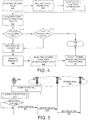
- Figure 4 illustrates an exemplary flow chart of for the UE to indicate to eNB its presence in the paging area in accordance with embodiments of the current invention.
- the UE enters RRC_IDLE mode.
- the UE performs cell selection or reselection to find a cell to camp on.
- the UE determines if the cell it detects supports CE.
- the UE prefers cells that support CE.
- the UE only selects cells that support CE.
- the UE camps on a cell that supports CE.
- the UE acquires the paging area information from the system information.
- the UE checks a stored paging area information exists. If UE has not stored any paging area information, i.e. there is no current value for the paging area, the UE moves to step 421. At step 421, the UE establishes RRC connection with the network. Subsequently, at step 422, the UE indicates its presence in the paging area to the network. Then the corresponding information of the paging area e.g. paging area identity or the neighboring cell list is stored by the UE at step 424. If at step 411, the UE determines that there is paging area information stored, it moves to step 412.
- the UE determines that there is paging area information stored, it moves to step 412.
- the UE determines that the received paging area is different from the stored paging area. If step 412 determines that there is no difference in the paging area, the UE moves to step 430 and ends the paging area updating procedure, and in one case, to establish a RRC connection with the original network as usual (not shown). If step 412 determines that there exists any difference between the received paging area and the stored paging area, the UE moves to step 421 and establishes a RRC connection with the network. When UE performs cell selection/reselection and camps on another cell, UE checks whether it moves into a different paging area.
- UE moves to a different paging area, it establishes a RRC connection with the network and indicates its presence in the new paging area to the network. Subsequently, at step 422, the UE indicates its presence in the paging area to the network. In one embodiment, the UE optionally sends its previously stored paging area information to the new base station (step 423). In another embodiment, the corresponding information of the paging area e.g. paging area identity or the neighboring cell list is updated by the UE at step 424. Even if the RRC connection with the network is released, both the UE and the base stations keep the paging area information. The UE in RRC_IDLE can check whether it moves to a different paging area due to IDLE mode mobility by acquiring paging area information.
- the CE status of the UE changes with UE mobility or due to other factors such as environmental changes.
- the CE status indicates only CE-UE or non-CE-UE.
- different levels for a CE status are used. In either cases, the UE monitors its CE status, updates CE changes to the network accordingly.
- FIG. 5 illustrates an exemplary flow chart for a UE to indicate to eNB the change of the CE status in the paging area in accordance with embodiments of the current invention.
- a UE 501 camps on a cell served by an eNB 502. eNB 502, together with eNBs 503 and 504, form a paging area 505.
- UE 501 monitors the CE status at step 512.
- UE 501 upon detecting change of the coverage status of the UE, UE 501 updates its coverage status to the network. If UE 501 is in RRC_CONNECTED, UE 501 reports its coverage status directly. Otherwise, UE 501 establishes a RRC connection with the network for the purpose of coverage status update.
- UE 501 sends CE status change indication to eNB 502.
- eNB 502 updates the information with its neighboring eNBs in the same paging area 505.
- eNB 502 sends CE status change indication of UE 501 to eNB 503.
- eNB 502 sends CE status change indication of UE 501 to eNB 504.
- the above steps 522 and 523 perform either in parallel or in sequence.
- UE 501 reports its CE status periodically to the eNB. In one embodiment, such periodic report can be aligned with other UE periodic reports.
- Figure 6 illustrates an exemplary system level flow chart of the UE, the eNB and the MME for the paging procedure for UEs requiring CE in accordance with embodiments of the current invention.
- a UE 601 camps on an eNB 602.
- UE 601 requires CE.
- a paging area 605 includes eNBs 602, 603 and 604.
- eNBs 602, 603 and 604 communicates with an MME 606.
- Figure 6 includes a paging-area update procedure 610 including steps 611 to 613, a paging procedure 620 including steps 621 to 623, and a releasing procedure 630 including steps 631 to 633.
- UE 601 indicates its presence, with CE status, to eNB 602.
- eNB 602 stores UE 601 information to its CE UE list at step 612.
- eNB 602 shares UE 601 information with eNB 603 and 604 in the same paging area 605 at step 613.
- MME 606 sends paging request for UE 601 to all eNBs in the tracking area.
- eNB 602 checks if UE 601 requires CE. If yes in step 622, at step 623, eNB 602 pages UE 601 repeatedly by a repetition number. If no, eNB 602 pages UE 601 normally. Similarly, eNBs 603 and 604 in paging area 605 page UE 601 repeatedly by the repetition number because they determine that UE 601 requires CE. Or else eNBs 603 and 604 in paging area 605 page UE 601 normally, i.e. without repetition.
- the UE information for the specific UE requiring CE may be released by the eNBs belonging to the paging area under certain conditions, such as the coverage status of the UE becomes better and changes to normal mode, or the UE requiring CE is not successfully paged in a pre-defined number of tries, or eNBs in another paging area informs that the UE is out of the original paging area.
- eNB 602 detects one or more release UE information triggers / conditions for UE 601.
- eNB 602 releases UE 601 from its CE UE list.
- eNB 602 informs eNBs 603 and 604 of the releasing of UE 601.
- the enhancement for the paging procedure for CE UEs requires no changes at the MME level.
- the eNBs keeps track of UEs requiring CE and pages UEs differently based on their CE status.
- Figure 7 illustrates an exemplary flow chart for the eNB to page the UE requiring CE in accordance with embodiments of the current invention.
- the eNB receives paging request from the MME.
- the eNB at step 710, the eNB checks the stored UE information based on the paged UE ID.
- the eNB checks if the paged UE is a UE requiring CE, i.e., if the paged UE is a CE UE in the paging area. If step 702 determines no, the eNB pages the UE normally without repetition. If step 702 determines yes, the eNB pages the UE repeatedly by a repetition number.
- Figure 8 illustrates an exemplary flow diagram detailing procedures for eNBs in a paging area to store or update information of UEs requiring CE in accordance with embodiments of the current invention.
- Figure 8 includes a UE procedure 810 and an eNB procedure 830.
- UE 801 requires CE.
- UE 801 camps on eNB 802 and acquires the paging area information.
- eNB 802, together with eNBs 803 and 804 form a paging area 805.
- UE 801 checks stored coverage area information.
- UE 801 determines if there is paging area changes between the receiving paging area from eNB 802 and the stored paging area information.
- UE 801 determines a paging area change if there was no previous stored paging area information or the received paging area is different from the stored paging area. Upon detecting paging area changes, UE 801 moves to step 821 and sends an RRCConnection Request message to eNB 802. At step 822, UE 802 receives an RRCConnection Setup message from eNB 802. At step 823, UE 801 sends an RRCConnection Complete message to eNB 802. In one embodiment, UE 801 includes the CE status indication or information in the RRCConnectionComplete or RRCConnectionRequest message.
- the UE establishes a RRC connection with establishment cause indicating a "paging area change.”
- eNB 802 upon receiving CE status information in the RRCConnectionComplete or RRCConnectionRequest message, stores the UE information in its CE UE list.
- the UE information includes the UE ID and the CE status.
- eNB 802 forwards the UE information to eNB 803.
- eNB 803 stores the UE information in its CE UE list.
- eNB 802 forwards the UE information to eNB 804.
- UE 804 stores the UE information in its CE UE list.
- Figure 9 shows an exemplary flow chart for the UE procedure of paging area handling when in the CE mode in accordance with embodiments of the current inventions.
- the UE requiring a CE receives information of a paging area from a base station in a wireless network, wherein the paging area is a subset of a tracking area for.
- the UE determines if there is any change between the received paging area and a stored paging area of the UE.
- the UE notifies the base station if there is any paging area change.
- the UE receives paging messages in the paging area, wherein the paging messages are transmitted repeatedly by a repetition number.
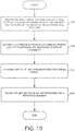
- Figure 10 shows an exemplary flow chart for the base station procedure of paging area handling when in the CE mode in accordance with embodiments of the current inventions.
- the base station stores information of a paging area, wherein the paging area is a geographic area covered by a cluster of neighboring base stations.
- the base station stores a CE (CE) UE list comprising UEs requiring CE.
- the base station updates the CE UE list upon detecting triggering event.
- the base station pages the UEs on the CE UE list repeatedly by a repetition number.
- CE CE
- the wireless network can page the UEs in CE mode efficiently.
- Such solution requires system level modifications and additional signaling procedures.
- Another possible solution is to require the UE to report the CE status to the network entity, such as the MME through eNB.
- the MME When the MME needs to page the UE, it will inform all the eNBs in the corresponding tracking area to page the UE with repetitions. This simplified solution, though less efficient, would require less signaling.
- FIG 11 illustrates an exemplary diagram of a UE in the CE mode reporting its CE status to the network in accordance with embodiments of the current invention.
- a UE 1101 camps on a cell served by an eNB 1102.
- eNB 1102 communicates with a network control entity, such as an MME 1103.
- UE 1101 monitors the CE status at step 1112.
- UE 1101 determines its being in the CE mode if the UE is a low cost UE.
- UE 1101 also determines its being in the CE mode if the normal UE requires CE.
- the UE upon detecting CE mode sends the CE status report to eNB 1102.
- UE 1101 If UE 1101 is in RRC CONNECTED, UE 1101 reports its coverage status directly. Otherwise, UE 1101 establishes a RRC connection with the network for the purpose of coverage status report.
- eNB 1102 Upon receiving the CE status report from UE 1101, eNB 1102 sends the CE status report to MME 1103.
- UE 1101 reports its CE status upon entering a new tracking area.
- the CE status report from the UE includes a CE status of the UE and a corresponding cell ID for the UE.
- the eNB relays the UE CE status report directly to the MME.
- the CE status report from the UE includes the CE status of the UE only.
- the eNB adds corresponding cell information in its CE status report and sends the CE status of the UE and the corresponding cell ID for the UE to MME.
- FIG. 12 illustrates an exemplary paging procedure that the MME informs the eNBs with CE status such that the paging message to the UE is sent repeatedly in accordance with embodiments of the current invention.
- UE 1201 requires CE.
- UE 1201 in idle mode resides in a tracking area 1206 served by eNBs 1202, 1203, and 1204, which are connected with a network entity, such as MME 1205 via S1 interface.
- MME 1205 determines the CE status of UE 1201.
- MME 1205 sends information to all base stations in tracking area 1206.
- MME 205 sends paging requests to eNBs 1204, 1203 and 1202, respectively.
- the paging response back to the MME is initiated on NAS layer and is sent by the eNBs based on NAS-level routing information.
- the eNB belonging to the tracking area indicated in the S1AP paging message performs paging of the UE over the radio interface by sending paging message on the cells repeatedly.
- the base stations in tracking area 1206 upon detecting CE information in the S1AP paging message indicating CE is required for the paged UE, the base stations in tracking area 1206 send page messages to UE 1201 repeatedly by a repetition.
- eNBs 1204, 1203 and 1202 send paging messages to UE 1201 repeatedly at steps 1231, 1232 and 1233, respectively.
- the repetition number is provided to the base stations by the MME.
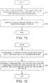
- FIG 13 illustrates an exemplary diagram of the MME sending the CE status information to all eNBs in the tracking area such that the paging messages are sent repeatedly in accordance with embodiments of the current invention.
- a tracking area 110 served by MME 141 includes eNBs 111 to 116, each covers a geographical area.
- MME 141 acquires the CE status of UE 1301.
- MME 141 stores CE status information of UE 1301.
- MME 141 Upon a mobile terminating call being initiated to UE 1301, MME 141 sends paging requests to all eNBs in tracking area 110.
- MME 141 sends the paging request to all base stations in tracking area 110 and indicates CE information of the paged UE.
- eNBs 111 to 116 pages UE 1301 Upon receiving the paging request with CE information from MME 141, eNBs 111 to 116 pages UE 1301 repeatedly by a repetition number.
- the repetition number is provided by MME 141.
- the repetition number is included in the paging request message.
- the eNBs derives its own repetition number based on the information from the MME.
- the repetition number is based on the CE status.
- Figure 14 illustrates an exemplary flow chart of the UE requiring CE reporting its CE status to the network in accordance with embodiments of the current invention.
- the UE detects a CE mode in a wireless network.
- the UE sends a CE report indicating the CE mode to the network.
- the UE receives a paging message from the network, wherein the paging message is transmitted repeatedly by a repetition number.
- Figure 15 illustrates of an exemplary flow chart of the eNB paging the UE requiring CE in accordance with embodiments of the current invention.
- the base station receives a paging request for a UE in a CE mode from a network entity in a wireless network.
- the base station sends a paging message repeatedly by a repetition number to the UE.
- Figure 16 illustrates of an exemplary flow chart of the MME sending UE CE status to the base stations in the tracking area in accordance with embodiments of the current invention.
- the network entity determines a CE mode for a UE in a wireless network.
- the network entity sends a paging request for the UE to one or more base stations in a tracking area of the UE, wherein the paging request indicates the CE mode for the UE.
Abstract
Description
- This application claims priority from Chinese Application Number
CN201410195278.9 - The disclosed embodiments relate generally to wireless communication, and, more particularly, to optimized mechanism for paging transmission and reception.
- Extending the reach of wireless communication is a challenge for all types of network, especially in the rural or remote areas. Due to the nature of the radio environment, services and power are difficult to deliver. It is both impractical and uneconomical to deliver coverage using a traditional base station approach. Taking LTE for example, it will be deployed at higher carrier frequencies than existing 2G and 3G systems, which implies higher propagation losses for LTE and potentially a need to add more sites to ensure sufficiently good coverage. Adding sites is costly and requires lengthy negotiations. Machine-to-Machine (M2M) applications required low-cost devices and improved coverage other than the current cellular communication system. For example, some smart metering deceives are often installed in the basements of residential buildings or locations shielded by foil-backed insulation, metalized windows, or traditional thick-walled building construction. These smart devices suffer a significantly larger path-loss, such as 20dB path loss, than that in the typical operation condition of normal devices. In order to ensure the network provides the best possible solutions to maximize coverage and serves the specific devices, the 3rd generation partnership project (3GPP) RANI working group has studied for coverage improvement for devices requiring coverage extension/coverage enhancement (CE). Some potential solutions have been identified such as repetition of the physical channels to improve the coverage.
- For network-originated data transfer to UEs requiring CE, some challenges are expected when they are in RRC_IDLE, which include the network does not know which cell the UE camps on, and whether the UE requires CE or not. Therefore, the network would not know whether to page the UE with CE through transmission repetitions. One possible solution is that on the network side, the MME assumes the UE does not require CE. The network pages the UE normally without requiring the knowledge of the UE CE status. However, under this approach since there is no HARQ process for paging, the UE requiring CE normally cannot receive the paging message in one paging occasion, which means the UE is unreachable.
- Improvement and enhancement are required to efficiently paging the UEs requiring CE in the wireless network.
- Methods and apparatus are provided for paging transmission and reception for UE requiring CE .
- In one novel aspect, a paging area, which is a geographic area covered by a subset of cells of a tracking area, is used for CE UEs. In one embodiment, the paging area is identified by an identity (ID) or a neighboring cell list, which is acquired from the broadcast information. The UE receives the paging area information, and notifies the network of its presence and updates the stored paging area information upon detecting any changes between the received paging area and a stored paging area. In one embodiment, the UE establishes a RRC connection to indicate its presence. In another embodiment, the UE establishes a RRC connection with establishment cause indicating a "paging area change." In one embodiment, the UE receives the paging area information from the system information (SI). In another embodiment, the UE reports its CE status upon detecting changes of the CE status. In one embodiment, the UE reports its CE status periodically. In yet another embodiment, the UE reports its previously stored paging area information upon detecting changes of paging area information between the received paging area and the stored paging area.
- In one novel aspect, the base station broadcasts its paging area information in the system information. The base station stores the UE information upon receiving presence indication from the UE requiring CE and forwards the information to neighboring base stations in the same paging area. The base station pages UE on the CE UE list with repetition and other UEs normally. In one embodiment, the base station releases the UE information from its CE UE list if one or more release triggering events are detected, including the UE is not successfully paged for a number of tries or for a period, being informed by another group of neighboring eNBs that the UE has moved out of the paging area.
- In another novel aspect, the MME acquires CE status of a UE. The MME determines a paging repetition number if the paged UE is in CE mode. The MME notifies the one or more eNBs that the paging is for UEs of low cost or requiring CE. In one embodiment, the MME provides a repetition number to the base stations in the same tracking area such that the base stations send the paging messages repeatedly by the repetition number. In another embodiment, the MME receives CE related information from a base station. The CE related information includes the UE CE status and the corresponding cell ID.
- Other embodiments and advantages are described in the detailed description below. This summary does not purport to define the invention. The invention is defined by the claims.
- The accompanying drawings, where like numerals indicate like components, illustrate embodiments of the invention.
-
Figure 1 illustrates an exemplary wireless communication network with UEs requiring CE in accordance with embodiments of the current invention. -
Figure 2 illustrates an exemplary paging procedure between UE, eNB and MME for the paging procedure for the UE requiring CE in accordance with embodiments of the current invention. -
Figure 3 illustrates a wireless communication system with each paging area organized with one or more than one eNBs in accordance with embodiments of the invention. -
Figure 4 illustrates an exemplary flow chart of for the UE to indicate to eNB its presence in the paging area in accordance with embodiments of the current invention. -
Figure 5 illustrates an exemplary flow chart for a UE to indicate to eNB the change of the CE status in the paging area in accordance with embodiments of the current invention. -
Figure 6 illustrates an exemplary system level flow chart of the UE, the eNB and the MME for the paging procedure for UEs requiring CE in accordance with embodiments of the current invention. -
Figure 7 illustrates an exemplary flow chart for the eNB to page the UE requiring CE in accordance with embodiments of the current invention. -
Figure 8 illustrates an exemplary flow diagram detailing procedures for eNBs in a paging area to store or update information of UEs requiring CE in accordance with embodiments of the current invention. -
Figure 9 shows an exemplary flow chart for the UE procedure of paging area handling when in the CE mode in accordance with embodiments of the current inventions. -
Figure 10 shows an exemplary flow chart for the base station procedure of paging area handling when in the CE mode in accordance with embodiments of the current inventions. -
Figure 11 illustrates an exemplary diagram of a UE in the CE mode reporting its CE status to the network in accordance with embodiments of the current invention. -
Figure 12 illustrates an exemplary paging procedure that the MME informs the eNBs with CE status such that the paging message to the UE is sent repeatedly in accordance with embodiments of the current invention. -
Figure 13 illustrates an exemplary diagram of the MME sending the CE status information to all eNBs in the tracking area such that the paging messages are sent repeatedly in accordance with embodiments of the current invention. -
Figure 14 illustrates an exemplary flow chart of the UE requiring CE reporting its CE status to the network in accordance with embodiments of the current invention. -
Figure 15 illustrates of an exemplary flow chart of the eNB paging the UE requiring CE in accordance with embodiments of the current invention. -
Figure 16 illustrates of an exemplary flow chart of the MME sending UE CE status to the base stations in the tracking area in accordance with embodiments of the current invention. - Reference will now be made in detail to some embodiments of the invention, examples of which are illustrated in the accompanying drawings.
-
Figure 1 illustrates an exemplarywireless communication network 100 with UEs requiring CE in accordance with embodiments of the current invention.Wireless communication system 100 includes multiple fixed base infrastructure units, such as base stations 111-116 and base stations 121-124, forming a network distributed over a geographical region, each base station covers a geographical area. The base unit may also be referred to as an access point, an access terminal, a base station, a Node-B, an eNode-B, or by other terminology used in the art. The one or more base stations 111-116 and 121-124 serve a number ofmobile stations - In one embodiment,
mobile communication network 100 comprises a plurality of base stations eNBs and a plurality of mobile stations, such asmobile stations eNB 111 and communicates witheNB 111 throughradio link 117. UE 101 requires CE. The data blocks overlink 117 needs to be repeatedly transmitted so that UE 101 can receive the transmission correctly.Normal UEs eNBs 116 and 121, respectively.UEs eNBs 116 and 121 throughradio links - A network entity, such as a mobility management entity (MME) 141 is connected with base stations such as eNB 111-116 and 121-124, via exemplary links such as 137-139. Though not shown the drawings, each eNB of
wireless network 100 may have a link withMME 141. Inwireless network 100, paging procedures are initiated by a network entity such asMME 141. One or more cells or eNBs form a tracking area. For example, atracking area 110 is formed includingeNBs 111 to 116 or cells served byeNBs 111 to 116. Atracking area 120 includes eNBs 121 to 124 or cells served by eNBs 121 to 124. While UEs are in the idle mode, the locations of UEs are known by MME, at the track area level. When the network needs to page a UE, the MME sends the paging message to all the eNBs in the tracking area where the UE resides. For example,MME 141 sends the paging message to all eNBs in trackingarea 110 when it needs to page idle-mode UE 101 or idle-mode UE 102. Similarly, when paging idle-mode UE 103,MME 141 sends paging message to all eNBs in trackingarea 120. - In one example, UE 101 requires CE, which means data blocks needs to be transmitted repeated so that UE 101 can receive them correctly. Therefore, paging message to idle-mode UE 101 needs to be repeatedly transmitted over different subframes by a repetition. In doing so, eNBs 111-116 all need to transmit the paging messages repeatedly by the repetition number. Large amount of data traffic in tracking
area 110 is generated. In one novel aspect, paging areas formed, each consists of a subset of eNBs or cells of a tracking area. Each eNB keeps track of the UEs requiring CE in the paging area. eNBs in the same paging area exchanges CE UE information via the X2 interface. UEs requiring CE reports its CE status to the serving cell. - In one embodiment, the communication system utilizes RRC layer to control communications between a UE and an eNB at the radio interface and the mobility of a UE crossing cells. RRC layer performs system information broadcasting/reception, paging, RRC connection establishment/release, NAS information transfer, mobility control and so on. Exemplary of RRC layer includes the developing Long Term Evolution (LTE) of the 3GPP UMTS standard.
- In another embodiment, the communication system utilizes NAS layer to control communications between a UE and MME. NAS layer performs EPS bearer management, authentication, ECM-IDLE mobility handling, paging origination in ECM-IDLE and security control. Exemplary of NAS layer includes the developing Long Term Evolution (LTE) of the 3GPP UMTS standard.
-
Figure 1 further shows simplified block diagrams 160, 150 and 170 for mobile station 101, andbase station 111 andMME 141, respectively, in accordance with the current invention. - The
eNB 111 has anantenna 155, which transmits and receives radio signals. ARF transceiver module 153, coupled with the antenna, receives RF signals fromantenna 155, converts them to baseband signals, and sends them toprocessor 152.RF transceiver 153 also converts received baseband signals fromprocessor 152, converts them to RF signals, and sends out toantenna 155.Processor 152 processes the received baseband signals and invokes different functional modules to perform features ineNB 111.Memory 151 stores program instructions anddata 154 to control the operations ofeNB 111.eNB 111 also includes a set of control modules, such as apaging area handler 156, a UECE status handler 157 andpaging module 158, to carry out functional tasks and page mobile stations. Pagingarea handler 156 are functions and communicates with eNB and UE to implement the paging area methods. In another case, if the paging area is not formed, so the paging with repetition could be implemented, so in this case, thepaging area handler 156 could be omitted, andpaging module 158 could be used to page UE to implement the paging without paging area information, for example, the paging UE with repetition, or normally paging without repetition. UECE status handler 157 performs tasks such the network entity can acquire CE status of UEs. - Mobile station 101 has an
antenna 165, which transmits and receives radio signals. ARF transceiver module 163, coupled with the antenna, receives RF signals fromantenna 165, converts them to baseband signals, and sends them toprocessor 162.RF transceiver 163 also converts received baseband signals fromprocessor 162, converts them to RF signals, and sends out toantenna 165.Processor 162 processes the received baseband signals and invokes different functional modules to perform features in mobile station 101.Memory 161 stores program instructions and data 166 to control the operations of mobile station 101. - Mobile station 101 also includes a set of control modules that carry out functional tasks. An
information handler 191 stores information of a paging, e.g. the paging message. The paging area is a subset of a tracking area for a paging message. Apaging area handler 192 receives information of a paging area from a base station in a wireless network when the UE requires CE, determines if there is any change between the paging area and the stored paging area of the UE, and notifies the base station if there is any paging area change. Apaging module 193 receives and processes paging messages in the paging area, wherein the page messages are transmitted repeatedly by a repetition number. In another embodiment, the paging area is not formed, so thepaging area handler 192 could be omitted, and thepaging module 193 receives and processes paging messages, wherein a repetition number transmits the paging messages repeatedly. A CE status handler 194 detects UE CE status and forwards the status to the network entity. -
MME 141 has atransceiver module 173 that receives messages, and sends them toprocessor 172.Transceiver 173 also converts received signals fromprocessor 172 and sends the signals to other entities.Processor 172 processes the received signals and invokes different functional modules to perform features inMME 141.Memory 171 stores program instructions anddata 174 to control the operations ofMME 141.MME 141 also includes control modules, such asCE status handler 177, to carry out the function and tasks forMME 141, andpaging module 178 to carry out the function and tasks for paging the UE in the tracking area. -
Figure 2 illustrates an exemplary paging procedure between UE, eNB, and MME for the paging procedure for the UE requiring CE in accordance with embodiments of the current invention.UE 201 requires CE.UE 201 in idle mode resides in the tracking area served byeNBs MME 205 via S1 interface. From the network side, if there is a terminating call towards a UE in RRC_IDLE, the MME initiates the paging procedure by sending PAGING message to each eNB with cells belonging to the tracking area(s) in which the UE is registered over the S1 interface using the SI application protocol (S1AP). Paging requests are sent to the relevant eNBs according to the mobility information kept in the UE's MME context in the serving MME. Atsteps MME 205 sends paging requests toeNBs UE 201, paging-related information transmission over physical channels (PDSCH and possibly PDCCH) may need repetitions across multiple subframes. Atsteps 231 to 233,eNBs UE 201 with repetitions, respectively. - In order to save the radio resources of paging with repetitions, which occurs in the whole tracking area, smaller geographic area than the tracking area is defined in the embodiments of this invention. If the UEs requiring CE are largely stationary, it is assumed that those UEs stay in the area in a relatively long period of time. Also for the machine type communication (MTC) UE with low mobility status or stationary, such assumption is also applicable. A geographic area called paging area is used for paging the UEs requiring CE with low mobility status or being stationary. The paging area is covered by one or more eNBs, which are in the neighborhood and communicated with each other through X2 interface. Although the paging message is generated from MME, who pages the UE in all the cells of the tracking area, only the cells belonging to the paging area where the UE requiring CE is present needs to transmit the paging message with repetitions for coverage enhancement. For example,
eNBs UE 201 resides in the paging area. In one novel aspect, only eNBs 202 and 204pages UE 201 with the same repetition number or a different repetition number.eNB 203 upon receiving the paging request fromMME 205,pages UE 201 without repetition. In one embodiment, the same number of paging repetitions is applied in all the cells belonging to the paging area for one specific UE requiring CE. The repetition number is determined at least based on the coverage status of the paged UE. -
Figure 3 illustrates a wireless communication system with each paging area organized with one or more than one eNBs in accordance with embodiments of the invention. Atracking area 110 served byMME 141 as shown inFigure 3 , the same as shown inFigure 1 , includeseNBs 111 to 116, each covers a geographical area. In one novel aspect, multiple paging areas are formed each includes a subset of eNBs in the tracking area. For example,eNBs paging area 310.eNB 113 forms apaging area 320.eNBs paging area 330. Thepaging area 310 is formed through the coordination betweeneNB 111 andeNB 112 overX2 interface 131. Thepaging area 330 is formed through the coordination betweeneNBs X2 interface - Since the paging area is covered by a group of cells, it can be identified by a cell lists. For E-UTRAN, each entry of the cell lists corresponds to the E-UTAN Cell Global Identifier (ECGI) and Physical Cell Identifier (PCI) of the cell. Alternatively, the paging area can be identified by a paging area identity. For example, different paging area will have a different identity, which can be identified uniquely over a wide area. In order to make the UEs requiring CE know which paging area the cell where it camps on, the paging-area related information , such as cell lists or paging area identity, needs to be broadcast in the system information. Each eNB can contain cells belonging to different paging areas, whereas each cell can only belong to one paging area.
- The paging area information is derived through coordination between the neighboring eNBs under the management of the MME. The paging area is identified by an identity or a neighboring cell list. eNBs which provide coverage to the same paging area should have the same paging area identity or the same neighboring cell list. The paging area information is broadcast by eNBs.
- eNBs in the paging area consider the UE is a new comer if no UE information for the UE requiring CE has been stored by them.
UE 301 in idle mode camps on the cell ofeNB 111 for the first time. In this case, if the CE indication fromUE 301 is received,eNB 111 shares this information witheNB 112 in the same paging area. Since each eNBs shares the UE information with the neighboring eNBs, the UE information for a specific UE requiring CE is kept by all the eNBs in the paging area, even if the RRC connection of the UE is released. The UE information for the UE requiring CE, which is shared by the eNBs in the paging area includes UE identity as well as the CE status. WhenUE 301 moves to a new location served byeNB 113, denoted by UE 301-M, the UE notifieseNB 113 of its presence upon detecting different paging area through the broadcasted system information. Similarly,eNB 113 would share information of UE 301-M with eNBs in the same paging area. In this example, there is no other eNBs in the same paging area aseNB 113. -
Figure 4 illustrates an exemplary flow chart of for the UE to indicate to eNB its presence in the paging area in accordance with embodiments of the current invention. Atstep 401, the UE enters RRC_IDLE mode. Subsequently, atstep 401, the UE performs cell selection or reselection to find a cell to camp on. In one embodiment, if UE determines that it requires CE, the UE determines if the cell it detects supports CE. In one embodiment, the UE prefers cells that support CE. In another embodiment, the UE only selects cells that support CE. Atstep 403, the UE camps on a cell that supports CE. Atstep 404, the UE acquires the paging area information from the system information. Atstep 411, the UE checks a stored paging area information exists. If UE has not stored any paging area information, i.e. there is no current value for the paging area, the UE moves to step 421. Atstep 421, the UE establishes RRC connection with the network. Subsequently, atstep 422, the UE indicates its presence in the paging area to the network. Then the corresponding information of the paging area e.g. paging area identity or the neighboring cell list is stored by the UE atstep 424. If atstep 411, the UE determines that there is paging area information stored, it moves to step 412. Atstep 412, the UE determines that the received paging area is different from the stored paging area. Ifstep 412 determines that there is no difference in the paging area, the UE moves to step 430 and ends the paging area updating procedure, and in one case, to establish a RRC connection with the original network as usual (not shown). Ifstep 412 determines that there exists any difference between the received paging area and the stored paging area, the UE moves to step 421 and establishes a RRC connection with the network. When UE performs cell selection/reselection and camps on another cell, UE checks whether it moves into a different paging area. If UE moves to a different paging area, it establishes a RRC connection with the network and indicates its presence in the new paging area to the network. Subsequently, atstep 422, the UE indicates its presence in the paging area to the network. In one embodiment, the UE optionally sends its previously stored paging area information to the new base station (step 423). In another embodiment, the corresponding information of the paging area e.g. paging area identity or the neighboring cell list is updated by the UE atstep 424. Even if the RRC connection with the network is released, both the UE and the base stations keep the paging area information. The UE in RRC_IDLE can check whether it moves to a different paging area due to IDLE mode mobility by acquiring paging area information. - The CE status of the UE changes with UE mobility or due to other factors such as environmental changes. In one embodiment, the CE status indicates only CE-UE or non-CE-UE. In another embodiment, different levels for a CE status are used. In either cases, the UE monitors its CE status, updates CE changes to the network accordingly.
-
Figure 5 illustrates an exemplary flow chart for a UE to indicate to eNB the change of the CE status in the paging area in accordance with embodiments of the current invention. Atstep 511, aUE 501 camps on a cell served by aneNB 502.eNB 502, together witheNBs paging area 505.UE 501 monitors the CE status atstep 512. At step 513, upon detecting change of the coverage status of the UE,UE 501 updates its coverage status to the network. IfUE 501 is in RRC_CONNECTED,UE 501 reports its coverage status directly. Otherwise,UE 501 establishes a RRC connection with the network for the purpose of coverage status update. In one embodiment, atstep 521,UE 501 sends CE status change indication toeNB 502. Upon receiving the CE status change indication fromUE 501,eNB 502 updates the information with its neighboring eNBs in thesame paging area 505. At step 522,eNB 502 sends CE status change indication ofUE 501 toeNB 503. Atstep 523,eNB 502 sends CE status change indication ofUE 501 toeNB 504. Theabove steps 522 and 523 perform either in parallel or in sequence. In another embodiment,UE 501 reports its CE status periodically to the eNB. In one embodiment, such periodic report can be aligned with other UE periodic reports. -
Figure 6 illustrates an exemplary system level flow chart of the UE, the eNB and the MME for the paging procedure for UEs requiring CE in accordance with embodiments of the current invention. AUE 601 camps on aneNB 602.UE 601 requires CE. Apaging area 605 includeseNBs eNBs MME 606.Figure 6 includes a paging-area update procedure 610 includingsteps 611 to 613, apaging procedure 620 includingsteps 621 to 623, and a releasingprocedure 630 including steps 631 to 633. - At
step 611,UE 601 indicates its presence, with CE status, toeNB 602.eNB 602stores UE 601 information to its CE UE list atstep 612.eNB 602shares UE 601 information witheNB same paging area 605 atstep 613. - At
step 621,MME 606 sends paging request forUE 601 to all eNBs in the tracking area. Atstep 622,eNB 602 checks ifUE 601 requires CE. If yes instep 622, atstep 623,eNB 602pages UE 601 repeatedly by a repetition number. If no,eNB 602pages UE 601 normally. Similarly,eNBs paging area 605page UE 601 repeatedly by the repetition number because they determine thatUE 601 requires CE. Or else eNBs 603 and 604 inpaging area 605page UE 601 normally, i.e. without repetition. - The UE information for the specific UE requiring CE may be released by the eNBs belonging to the paging area under certain conditions, such as the coverage status of the UE becomes better and changes to normal mode, or the UE requiring CE is not successfully paged in a pre-defined number of tries, or eNBs in another paging area informs that the UE is out of the original paging area. At step 631,
eNB 602 detects one or more release UE information triggers / conditions forUE 601. At step 632,eNB 602releases UE 601 from its CE UE list. Atstep 633,eNB 602 informseNBs UE 601. - In one novel aspect, the enhancement for the paging procedure for CE UEs, requires no changes at the MME level. The eNBs keeps track of UEs requiring CE and pages UEs differently based on their CE status.
Figure 7 illustrates an exemplary flow chart for the eNB to page the UE requiring CE in accordance with embodiments of the current invention. Atstep 701, the eNB receives paging request from the MME. The eNB, atstep 710, the eNB checks the stored UE information based on the paged UE ID. Atstep 702, the eNB checks if the paged UE is a UE requiring CE, i.e., if the paged UE is a CE UE in the paging area. Ifstep 702 determines no, the eNB pages the UE normally without repetition. Ifstep 702 determines yes, the eNB pages the UE repeatedly by a repetition number. -
Figure 8 illustrates an exemplary flow diagram detailing procedures for eNBs in a paging area to store or update information of UEs requiring CE in accordance with embodiments of the current invention.Figure 8 includes aUE procedure 810 and aneNB procedure 830.UE 801 requires CE. Atstep 811,UE 801 camps oneNB 802 and acquires the paging area information.eNB 802, together witheNBs 803 and 804 form apaging area 805. Atstep 810,UE 801 checks stored coverage area information. Atstep 812,UE 801 determines if there is paging area changes between the receiving paging area fromeNB 802 and the stored paging area information.UE 801 determines a paging area change if there was no previous stored paging area information or the received paging area is different from the stored paging area. Upon detecting paging area changes,UE 801 moves to step 821 and sends an RRCConnection Request message toeNB 802. Atstep 822,UE 802 receives an RRCConnection Setup message fromeNB 802. Atstep 823,UE 801 sends an RRCConnection Complete message toeNB 802. In one embodiment,UE 801 includes the CE status indication or information in the RRCConnectionComplete or RRCConnectionRequest message. In another embodiment, the UE establishes a RRC connection with establishment cause indicating a "paging area change." At step 831,eNB 802 upon receiving CE status information in the RRCConnectionComplete or RRCConnectionRequest message, stores the UE information in its CE UE list. In one embodiment, the UE information includes the UE ID and the CE status. Atstep 832,eNB 802 forwards the UE information to eNB 803. At step 833, eNB 803 stores the UE information in its CE UE list. Atstep 834,eNB 802 forwards the UE information toeNB 804. At step 835,UE 804 stores the UE information in its CE UE list. -
Figure 9 shows an exemplary flow chart for the UE procedure of paging area handling when in the CE mode in accordance with embodiments of the current inventions. Atstep 901, the UE requiring a CE receives information of a paging area from a base station in a wireless network, wherein the paging area is a subset of a tracking area for. Atstep 902, the UE determines if there is any change between the received paging area and a stored paging area of the UE. Atstep 903, the UE notifies the base station if there is any paging area change. Atstep 904, the UE receives paging messages in the paging area, wherein the paging messages are transmitted repeatedly by a repetition number. -
Figure 10 shows an exemplary flow chart for the base station procedure of paging area handling when in the CE mode in accordance with embodiments of the current inventions. Atstep 1001, the base station stores information of a paging area, wherein the paging area is a geographic area covered by a cluster of neighboring base stations. Atstep 1002, the base station stores a CE (CE) UE list comprising UEs requiring CE. Atstep 1003, the base station updates the CE UE list upon detecting triggering event. Atstep 1004, the base station pages the UEs on the CE UE list repeatedly by a repetition number. - Using paging area solutions, the wireless network can page the UEs in CE mode efficiently. Such solution requires system level modifications and additional signaling procedures. Another possible solution is to require the UE to report the CE status to the network entity, such as the MME through eNB. When the MME needs to page the UE, it will inform all the eNBs in the corresponding tracking area to page the UE with repetitions. This simplified solution, though less efficient, would require less signaling.
-
Figure 11 illustrates an exemplary diagram of a UE in the CE mode reporting its CE status to the network in accordance with embodiments of the current invention. Atstep 1111, aUE 1101 camps on a cell served by aneNB 1102.eNB 1102 communicates with a network control entity, such as anMME 1103.UE 1101 monitors the CE status atstep 1112. In one embodiment,UE 1101 determines its being in the CE mode if the UE is a low cost UE.UE 1101 also determines its being in the CE mode if the normal UE requires CE. At step 1121, the UE upon detecting CE mode, sends the CE status report toeNB 1102. IfUE 1101 is in RRC CONNECTED,UE 1101 reports its coverage status directly. Otherwise,UE 1101 establishes a RRC connection with the network for the purpose of coverage status report. Upon receiving the CE status report fromUE 1101,eNB 1102 sends the CE status report toMME 1103. In one embodiment,UE 1101 reports its CE status upon entering a new tracking area. In one embodiment, the CE status report from the UE includes a CE status of the UE and a corresponding cell ID for the UE. The eNB relays the UE CE status report directly to the MME. In another embodiment, the CE status report from the UE includes the CE status of the UE only. The eNB adds corresponding cell information in its CE status report and sends the CE status of the UE and the corresponding cell ID for the UE to MME. -
Figure 12 illustrates an exemplary paging procedure that the MME informs the eNBs with CE status such that the paging message to the UE is sent repeatedly in accordance with embodiments of the current invention.UE 1201 requires CE.UE 1201 in idle mode resides in atracking area 1206 served byeNBs MME 1205 via S1 interface. In one embodiment,MME 1205 determines the CE status ofUE 1201. Upon detecting thatUE 1201 requires CE,MME 1205 sends information to all base stations intracking area 1206. Atsteps MME 205 sends paging requests toeNBs tracking area 1206 send page messages toUE 1201 repeatedly by a repetition.eNBs UE 1201 repeatedly atsteps -
Figure 13 illustrates an exemplary diagram of the MME sending the CE status information to all eNBs in the tracking area such that the paging messages are sent repeatedly in accordance with embodiments of the current invention. Atracking area 110 served byMME 141, as shown inFigure 1 , includeseNBs 111 to 116, each covers a geographical area. AUE 1301, requiring CE, camps oneNB 116.MME 141 acquires the CE status ofUE 1301. In one embodiment,MME 141 stores CE status information ofUE 1301. Upon a mobile terminating call being initiated toUE 1301,MME 141 sends paging requests to all eNBs in trackingarea 110. In one novel aspect,MME 141 sends the paging request to all base stations in trackingarea 110 and indicates CE information of the paged UE. Upon receiving the paging request with CE information fromMME 141,eNBs 111 to 116pages UE 1301 repeatedly by a repetition number. In one embodiment, the repetition number is provided byMME 141. In one embodiment, the repetition number is included in the paging request message. In another embodiment, the eNBs derives its own repetition number based on the information from the MME. In yet another embodiment, the repetition number is based on the CE status. -
Figure 14 illustrates an exemplary flow chart of the UE requiring CE reporting its CE status to the network in accordance with embodiments of the current invention. Atstep 1401, the UE detects a CE mode in a wireless network. Atstep 1402, the UE sends a CE report indicating the CE mode to the network. Atstep 1403, the UE receives a paging message from the network, wherein the paging message is transmitted repeatedly by a repetition number. -
Figure 15 illustrates of an exemplary flow chart of the eNB paging the UE requiring CE in accordance with embodiments of the current invention. Atstep 1501 the base station receives a paging request for a UE in a CE mode from a network entity in a wireless network. Atstep 1502, the base station sends a paging message repeatedly by a repetition number to the UE. -
Figure 16 illustrates of an exemplary flow chart of the MME sending UE CE status to the base stations in the tracking area in accordance with embodiments of the current invention. Atstep 1601, the network entity determines a CE mode for a UE in a wireless network. Atstep 1602, the network entity sends a paging request for the UE to one or more base stations in a tracking area of the UE, wherein the paging request indicates the CE mode for the UE. - Although the present invention has been described in connection with certain specific embodiments for instructional purposes, the present invention is not limited thereto. Accordingly, various modifications, adaptations, and combinations of various features of the described embodiments can be practiced without departing from the scope of the invention as set forth in the claims.
- The present invention can also be described based on the following clauses:
- 1. A method comprising:
- receiving information of a paging area by a user equipment (UE) requiring a coverage extension/coverage enhancement (CE) from a base station in a wireless network, wherein the paging area is a subset of a tracking area;
- determining if there is any change between the received paging area and a stored paging area of the UE;
- notifying the base station if there is any paging area change; and
- receiving paging messages in the paging area, wherein the paging messages are transmitted repeatedly by a repetition number.
- 2. The method of
clause 1, wherein the notifying the base station involves:- establishing a radio resource control (RRC) connection with the base station; and
- reporting a CE status of the UE to the base station.
- 3. The method of
clause 2, wherein an establishment cause IE of a RRC Connection Request for the RRC connection establishment indicating a paging area change. - 4. The method of
clause 2 further comprising:- reporting the stored paging area information to the base station.
- 5. The method of
clause 1 further comprising:- updating the stored paging area if there is paging area change.
- 6. The method of
clause 1 further comprising:- reporting the stored paging area information to the wireless network periodically.
- 7. The method of
clause 1 further comprising:- detecting a CE status change; and
- reporting the CE status change to the wireless network.
- 8. A method comprising:
- storing information of a paging area by a base station, wherein the paging area is a geographic area covered by a cluster of neighboring base stations;
- storing a coverage extension/coverage enhancement (CE)user equipment (UE) list comprising UEs requiring CE;
- updating the CE UE list upon detecting triggering event; and
- paging the UEs on the CE UE list repeatedly by a repetition number.
- 9. The method of clause 8, wherein the paging area is derived by coordinating among neighboring base stations identified by a base station ID or a neighboring cell list.
- 10. The method of clause 8 further comprising: broadcasting the information of the paging area in a system information message.
- 11. The method of clause 8 wherein the triggering event is receiving a notification of presence by a UE requiring CE.
- 12. The method of clause 11 wherein the notification of presence includes a CE status of the UE.
- 13. The method of clause 11 further comprising: establishing a radio resource control (RRC) connection with the UE, and wherein an establishment cause IE in a RRC Connection Request message for the RRC establishment indicates a paging area change.
- 14. The method of clause 11 further comprising: forwarding the UE notification of presence information to the base stations in the paging area.
- 15. The method of clause 8, wherein the triggering event is receiving a notification of CE UE presence from a neighboring base station.
- 16. The method of clause 8 further comprising: deleting a UE from the CE UE list upon detecting one or more releasing events.
- 17. The method of clause 16 wherein the release events comprising: failure to receive a paging response from the UE after repeatedly tries by the repetition number, failure to receive a paging response after a period of time, receiving a notification from a neighboring base station indicating the UE is out of the paging area.
- 18. A user equipment (UE) comprising
a transceiver that transmits and receives radio signals via a first radio access link;
an information handler that stores information of a stored paging area;
a paging area handler that receives information of a paging area from a base station when the UE requires coverage extension/coverage enhancement (CE), determines if there is any change between the paging area and the stored paging area of the UE, and notifies the base station if there is any paging area change; and
a paging module that receives and processes paging messages in the paging area, wherein the page messages are transmitted repeatedly by a repetition number. - 19. The UE of clause 18, wherein the paging area handler establishes a radio resource control (RRC) connection with the base station and reports a CE status of the UE to the base station.
- 20. The method of clause 19, wherein an establishment cause IE of a RRC Connection Request for the RRC connection establishment indicating a paging area change.
- 21. The method of clause 19, wherein the paging area handler further reports the stored paging area information to the wireless network.
- 22. The method of clause 18, wherein the information handler updates the stored paging area if there is paging area change.
- 23. The method of clause 18, wherein the paging area handler reports the stored paging area information to the wireless network periodically.
- 24. The method of clause 18, wherein the paging area handler reports CE status to the wireless network upon detecting a CE status change.
- 25. A method comprising:
- detecting a coverage extension/coverage enhancement (CE) mode by a user equipment (UE) in a wireless network;
- sending a CE message indicating the CE mode to the network; and
- receiving a paging message from the network, wherein the paging message is transmitted repeatedly by a repetition number.
- 26. The method of clause 25, wherein the CE mode is detected upon detecting one or more conditions comprising: the UE is a low cost device, or the UE requires CE.
- 27. The method of clause 25, wherein the sending the CE message comprising:
- establishing a radio resource control (RRC) connection with a base station; and
- reporting a CE status of the UE to the base station.
- 28. The method of clause 25 wherein the CE message to the network includes a CE status of the UE.
- 29. A method comprising:
- receiving a paging request for a UE in a coverage extension/coverage enhancement (CE) mode from a network entity by a base station in a wireless network; and
- sending a paging message repeatedly by a repetition number to the UE.
- 30. The method of clause 29, wherein the repetition number is provided by the network entity.
- 31. The method of clause 29, further comprising:
- receiving a CE message from the UE indicating a CE mode of the UE; and
- sending a CE information message to the network entity.
- 32. The method of clause 31, wherein the CE information message includes a CE status of the UE and a corresponding cell ID for the UE.
- 33. A method comprising:
- determining a coverage extension/coverage enhancement (CE) mode for a UE by a network entity in a wireless network; and
- sending a paging request for the UE to one or more base stations in a tracking area of the UE, wherein the paging request indicates the CE mode for the UE.
- 34. The method of clause 33 wherein the network entity is a mobility management entity (MME).
- 35. The method of clause 33 further comprising: providing the one or more base stations in the track area with a repetition number for the paging of the UE.
- 36. The method of clause 33 further comprising: receiving CE information of the UE from a base station.
- 37. The method of clause 36, wherein the CE information includes a CE status of the UE and a corresponding cell ID for the UE.
Claims (15)
- A method comprising:detecting a coverage extension/coverage enhancement, hereinafter CE, mode by a user equipment, hereinafter UE, in a wireless network, wherein the CE mode identifies the UE as being in a status of requiring enhanced coverage handling;sending a CE message indicating the CE mode to an eNB; andreceiving a paging message from the eNB, wherein the paging message is transmitted repeatedly by a repetition number.
- An apparatus comprising:a detector that detects a coverage extension/coverage enhancement, hereinafter CE, mode by a user equipment, hereinafter UE, in a wireless network, wherein the CE mode identifies the UE as being in a status of requiring enhanced coverage handling;a CE sender that sends a CE message indicating the CE mode to an eNB; and a CE receiver that receives a paging message from the eNB, wherein the paging message is transmitted repeatedly by a repetition number.
- The method of claim 1 or the apparatus of claim 2, wherein the CE mode is detected upon detecting one or more conditions comprising: the UE is a low cost device, or the UE requires CE.
- The method of claim 1 or the apparatus of claim 2, wherein the sending the CE message comprising:establishing a radio resource control, hereinafter RRC, connection with a base station; and reporting a CE status of the UE to the base station.
- The method of claim 1 or the apparatus of claim 2, wherein the CE message to the eNB includes a CE status of the UE.
- The method of claim 1 or the apparatus of claim 2, wherein the CE message to the eNB includes an update of a CE status of the UE.
- The method of claim 1 or the apparatus of claim 2, wherein the repetition number is determined by mobility management entity, hereinafter MME.
- A method comprising:receiving a paging request for a UE in a coverage extension/coverage enhancement, hereinafter CE, mode from a network entity by a base station in a wireless network, wherein the CE mode identifies the UE as being in a status of requiring enhanced coverage handling; andsending a paging message repeatedly by a repetition number to the UE.
- The method of claim 8, wherein the repetition number is provided by the network entity.
- The method of claim 8, further comprising:receiving a CE message from the UE indicating a CE mode of the UE; andsending a CE information message to the network entity;
wherein preferably the CE information message includes a CE status of the UE anda corresponding cell ID for the UE. - A method comprising:determining a coverage extension/coverage enhancement, hereinafter CE mode for a UE by a network entity in a wireless network, wherein the CE mode identifies the UE as being in a status of requiring enhanced coverage handling; andsending a paging request for the UE to one or more base stations in a tracking area of the UE, wherein the paging request indicates the CE mode for the UE, and wherein the paging request is transmitted repeatedly by a repetition number.
- The method of claim 11, wherein the network entity is a mobility management entity, hereinafter MME.
- The method of claim 11, further comprising: providing the one or more base stations in the track area with a repetition number for the paging of the UE.
- The method of claim 11, further comprising: receiving CE information of the UE from a base station.
- The method of claim 11, wherein the CE information includes a CE status of the UE and a corresponding cell ID for the UE.
Applications Claiming Priority (3)
| Application Number | Priority Date | Filing Date | Title |
|---|---|---|---|
| CN201410195278 | 2014-05-09 | ||
| EP15788556.7A EP3064005B1 (en) | 2014-05-09 | 2015-05-08 | Optimized mechanism for paging transmission and reception |
| PCT/CN2015/078557 WO2015169256A1 (en) | 2014-05-09 | 2015-05-08 | Optimized mechanism for paging transmission and reception |
Related Parent Applications (2)
| Application Number | Title | Priority Date | Filing Date |
|---|---|---|---|
| EP15788556.7A Division EP3064005B1 (en) | 2014-05-09 | 2015-05-08 | Optimized mechanism for paging transmission and reception |
| EP15788556.7A Division-Into EP3064005B1 (en) | 2014-05-09 | 2015-05-08 | Optimized mechanism for paging transmission and reception |
Publications (2)
| Publication Number | Publication Date |
|---|---|
| EP3346735A1 true EP3346735A1 (en) | 2018-07-11 |
| EP3346735B1 EP3346735B1 (en) | 2021-02-17 |
Family
ID=54392175
Family Applications (2)
| Application Number | Title | Priority Date | Filing Date |
|---|---|---|---|
| EP18152726.8A Active EP3346735B1 (en) | 2014-05-09 | 2015-05-08 | Optimized mechanism for paging transmission and reception |
| EP15788556.7A Active EP3064005B1 (en) | 2014-05-09 | 2015-05-08 | Optimized mechanism for paging transmission and reception |
Family Applications After (1)
| Application Number | Title | Priority Date | Filing Date |
|---|---|---|---|
| EP15788556.7A Active EP3064005B1 (en) | 2014-05-09 | 2015-05-08 | Optimized mechanism for paging transmission and reception |
Country Status (4)
| Country | Link |
|---|---|
| US (4) | US9622215B2 (en) |
| EP (2) | EP3346735B1 (en) |
| CN (2) | CN106465332B (en) |
| WO (1) | WO2015169256A1 (en) |
Families Citing this family (21)
| Publication number | Priority date | Publication date | Assignee | Title |
|---|---|---|---|---|
| CN104349457B (en) * | 2013-08-08 | 2018-05-11 | 电信科学技术研究院 | A kind of paging method, paging message acquisition methods and base station, terminal |
| EP3036950A2 (en) * | 2013-08-21 | 2016-06-29 | Telefonaktiebolaget LM Ericsson (publ) | Paging in coverage extension mode |
| CN105101044B (en) * | 2014-05-08 | 2020-03-10 | 夏普株式会社 | Paging message receiving/transmitting method and related device thereof |
| US20170374644A1 (en) * | 2014-12-15 | 2017-12-28 | Lg Electronics Inc. | Method for transmitting paging in wireless communication system, and apparatus therefor |
| US9749510B2 (en) | 2014-12-25 | 2017-08-29 | Panasonic Intellectual Property Management Co., Ltd. | Imaging unit and imaging apparatus |
| MX2018005020A (en) * | 2015-10-30 | 2018-06-13 | Ericsson Telefon Ab L M | Paging in extended coverage. |
| JP6549785B2 (en) | 2016-04-01 | 2019-07-24 | 京セラ株式会社 | User equipment and method |
| ES2776801T3 (en) | 2016-04-27 | 2020-08-03 | Ericsson Telefon Ab L M | Method and device for handling radio signaling extension |
| CN107371215B (en) * | 2016-05-13 | 2021-07-27 | 北京三星通信技术研究有限公司 | Method and equipment for controlling light connection |
| WO2017202443A1 (en) * | 2016-05-23 | 2017-11-30 | Sony Mobile Communications Inc. | Communication network device and method for executing paging to a user communication device |
| US10856209B2 (en) * | 2016-10-24 | 2020-12-01 | Qualcomm Incorporated | Paging area procedures and connection signaling |
| US10536921B1 (en) | 2017-04-04 | 2020-01-14 | Mbit Wireless, Inc. | Method and apparatus for providing location information |
| WO2018184227A1 (en) * | 2017-04-07 | 2018-10-11 | Guangdong Oppo Mobile Telecommunications Corp., Ltd. | Communication methods, devices and system |
| CN109548113B (en) * | 2017-08-08 | 2021-01-29 | 华为技术有限公司 | Paging method of user equipment and related equipment |
| CN109392035B (en) | 2017-08-09 | 2022-04-22 | 华为技术有限公司 | RNA distribution method, network equipment and terminal |
| CN110351815B (en) * | 2018-04-04 | 2022-05-27 | 中兴通讯股份有限公司 | Paging method, base station and user equipment |
| JP2021119643A (en) * | 2018-04-05 | 2021-08-12 | ソニーグループ株式会社 | Wireless communication device, communication device, and communication control method |
| US11812407B2 (en) | 2018-08-10 | 2023-11-07 | Beijing Xiaomi Mobile Software Co., Ltd. | Method and apparatus for sending and receiving information, base station and user equipment |
| CN113170413B (en) * | 2018-09-27 | 2023-06-02 | 上海诺基亚贝尔股份有限公司 | Method, apparatus and computer readable medium for paging |
| CN111491371A (en) * | 2020-04-07 | 2020-08-04 | 捷开通讯(深圳)有限公司 | Method and device for adjusting paging cycle, storage medium and electronic terminal |
| CN116097800A (en) * | 2020-08-07 | 2023-05-09 | 中兴通讯股份有限公司 | Wireless multi-carrier configuration and selection |
Citations (2)
| Publication number | Priority date | Publication date | Assignee | Title |
|---|---|---|---|---|
| WO2011025788A1 (en) * | 2009-08-24 | 2011-03-03 | Qualcomm Incorporated | Sending an uplink order to active set base stations |
| US20140098761A1 (en) * | 2012-10-05 | 2014-04-10 | Interdigital Patent Holdings, Inc. | Method and apparatus for enhancing coverage of machine type communication (mtc) devices |
Family Cites Families (20)
| Publication number | Priority date | Publication date | Assignee | Title |
|---|---|---|---|---|
| US6058308A (en) * | 1997-02-18 | 2000-05-02 | Telefonaktiebolaget L M Ericsson | Apparatus, and associated method, for adaptively selecting a paging area in which to page a mobile terminal |
| US6745039B1 (en) * | 2000-04-10 | 2004-06-01 | Telefonaktiebolaget L M Ericsson (Publ) | Self-configurable paging system for a cellular telecommunications network |
| US6477382B1 (en) * | 2000-06-12 | 2002-11-05 | Intel Corporation | Flexible paging for packet data |
| US7937096B2 (en) * | 2001-10-03 | 2011-05-03 | Ntt Docomo, Inc. | Method and associated apparatus for distributed dynamic paging area clustering under heterogeneous access networks |
| US7047050B1 (en) * | 2002-02-23 | 2006-05-16 | Motorola, Inc. | Method of monitoring a broadcast channel for a page at a mobile communication device |
| US20030225887A1 (en) * | 2002-05-28 | 2003-12-04 | Rene Purnadi | Establishing IP level connectivity by use of L-2 dormant mobile node activation |
| US20040254980A1 (en) * | 2002-06-05 | 2004-12-16 | Masayuki Motegi | Server, mobile communication system, positional information managing method, radio base station, mobile station method for calling in mobile communication system, and mobile communication method |
| KR100584446B1 (en) * | 2004-02-11 | 2006-05-26 | 삼성전자주식회사 | Method for controlling operation mode of mobile terminal in broadband wireless access communication system |
| CN100563358C (en) * | 2006-05-31 | 2009-11-25 | 华为技术有限公司 | A kind of system, Apparatus and method for of tackling mobile exchanging node fault |
| US8374625B2 (en) * | 2008-09-09 | 2013-02-12 | Nokia Siemens Networks Oy | Neighborhood paging group design for wireless networks |
| US8204517B1 (en) * | 2009-02-11 | 2012-06-19 | Sprint Spectrum L.P. | Method and system of paging a mobile station |
| US8428625B2 (en) * | 2009-02-27 | 2013-04-23 | Cisco Technology, Inc. | Paging heuristics in packet based networks |
| US8724448B2 (en) | 2009-07-03 | 2014-05-13 | Nokia Siemens Networks Oy | Enhanced physical downlink shared channel coverage |
| CN102035795B (en) * | 2009-09-30 | 2014-07-02 | 中兴通讯股份有限公司 | Transmission method of notification message of multimedia broadcasting multicast business, device and system thereof |
| US8611895B2 (en) * | 2009-10-30 | 2013-12-17 | Apple Inc. | Methods for optimizing paging mechanisms using device context information |
| CN102469584B (en) * | 2010-11-18 | 2014-04-16 | 华为技术有限公司 | Method, device and system for paging heterogeneous network |
| US9295030B2 (en) * | 2011-12-02 | 2016-03-22 | Qualcomm Incorporated | Methods and apparatuses for improved paging area identifier selection in wireless networks containing low power base stations |
| EP2849501B1 (en) * | 2012-05-09 | 2020-09-30 | Samsung Electronics Co., Ltd. | Method and apparatus for controlling discontinuous reception in mobile communication system |
| US10154483B2 (en) * | 2012-09-12 | 2018-12-11 | Qualcomm Incorporated | Coverage enhancement techniques for machine type communication devices in a wireless network |
| EP3036950A2 (en) * | 2013-08-21 | 2016-06-29 | Telefonaktiebolaget LM Ericsson (publ) | Paging in coverage extension mode |
-
2015
- 2015-05-08 EP EP18152726.8A patent/EP3346735B1/en active Active
- 2015-05-08 WO PCT/CN2015/078557 patent/WO2015169256A1/en active Application Filing
- 2015-05-08 CN CN201580022001.9A patent/CN106465332B/en active Active
- 2015-05-08 CN CN201910982429.8A patent/CN111031529A/en active Pending
- 2015-05-08 EP EP15788556.7A patent/EP3064005B1/en active Active
- 2015-10-21 US US14/918,773 patent/US9622215B2/en active Active
-
2017
- 2017-03-07 US US15/451,581 patent/US9854560B2/en active Active
- 2017-03-07 US US15/451,596 patent/US9872274B2/en active Active
- 2017-11-28 US US15/823,958 patent/US10212691B2/en active Active
Patent Citations (2)
| Publication number | Priority date | Publication date | Assignee | Title |
|---|---|---|---|---|
| WO2011025788A1 (en) * | 2009-08-24 | 2011-03-03 | Qualcomm Incorporated | Sending an uplink order to active set base stations |
| US20140098761A1 (en) * | 2012-10-05 | 2014-04-10 | Interdigital Patent Holdings, Inc. | Method and apparatus for enhancing coverage of machine type communication (mtc) devices |
Also Published As
| Publication number | Publication date |
|---|---|
| US20160044633A1 (en) | 2016-02-11 |
| US20170195989A1 (en) | 2017-07-06 |
| US9854560B2 (en) | 2017-12-26 |
| EP3346735B1 (en) | 2021-02-17 |
| EP3064005A4 (en) | 2017-06-28 |
| US9872274B2 (en) | 2018-01-16 |
| CN106465332B (en) | 2019-10-29 |
| US20180084526A1 (en) | 2018-03-22 |
| CN106465332A (en) | 2017-02-22 |
| EP3064005A1 (en) | 2016-09-07 |
| US10212691B2 (en) | 2019-02-19 |
| EP3064005B1 (en) | 2018-03-28 |
| US9622215B2 (en) | 2017-04-11 |
| US20170181120A1 (en) | 2017-06-22 |
| WO2015169256A1 (en) | 2015-11-12 |
| CN111031529A (en) | 2020-04-17 |
Similar Documents
| Publication | Publication Date | Title |
|---|---|---|
| US10212691B2 (en) | Optimized mechanism for paging transmission and reception | |
| US11051155B2 (en) | Communication system | |
| US11006427B2 (en) | Communication system, base station, and communication terminal for controlling interference from neighboring cells | |
| CN107431941B (en) | Triggering conditions for measurement reporting for relay selection | |
| CN107027095B (en) | Machine-to-machine (M2M) terminal, base station and method | |
| US10200968B2 (en) | Paging message receiving/transmitting method and related user equipment, base station and network side device | |
| EP3105982B1 (en) | Method and apparatus for indicating change of coverage enhancement mode in wireless communication system | |
| US9820254B2 (en) | Mobile communication system | |
| US20170048822A1 (en) | Method and apparatus for indicatinag d2d resource pool in wireless communication system | |
| US10595195B2 (en) | Method and apparatus for transmitting UE ID in wireless communication system | |
| KR102109410B1 (en) | Apparatus and method for transmitting geographical information by D2D terminal in wireless communication system | |
| US10028310B2 (en) | Method and apparatus for transmitting information on device-to-device resources in wireless communication system | |
| WO2016119442A1 (en) | Paging method, device, mme, base station, and user equipment | |
| EP2952059B1 (en) | Device-anchor base station selection and detection | |
| CN102149195A (en) | Method and system for processing public configuration information | |
| EP4255025A1 (en) | Communication system and communication terminal | |
| US20180288649A1 (en) | Method and apparatus for performing application specific congestion control for data communication in wireless communication system |
Legal Events
| Date | Code | Title | Description |
|---|---|---|---|
| PUAI | Public reference made under article 153(3) epc to a published international application that has entered the european phase |
Free format text: ORIGINAL CODE: 0009012 |
|
| STAA | Information on the status of an ep patent application or granted ep patent |
Free format text: STATUS: THE APPLICATION HAS BEEN PUBLISHED |
|
| AC | Divisional application: reference to earlier application |
Ref document number: 3064005 Country of ref document: EP Kind code of ref document: P |
|
| AK | Designated contracting states |
Kind code of ref document: A1 Designated state(s): AL AT BE BG CH CY CZ DE DK EE ES FI FR GB GR HR HU IE IS IT LI LT LU LV MC MK MT NL NO PL PT RO RS SE SI SK SM TR |
|
| STAA | Information on the status of an ep patent application or granted ep patent |
Free format text: STATUS: REQUEST FOR EXAMINATION WAS MADE |
|
| 17P | Request for examination filed |
Effective date: 20190110 |
|
| RBV | Designated contracting states (corrected) |
Designated state(s): AL AT BE BG CH CY CZ DE DK EE ES FI FR GB GR HR HU IE IS IT LI LT LU LV MC MK MT NL NO PL PT RO RS SE SI SK SM TR |
|
| STAA | Information on the status of an ep patent application or granted ep patent |
Free format text: STATUS: EXAMINATION IS IN PROGRESS |
|
| RAP1 | Party data changed (applicant data changed or rights of an application transferred) |
Owner name: HFI INNOVATION INC. |
|
| 17Q | First examination report despatched |
Effective date: 20190813 |
|
| GRAP | Despatch of communication of intention to grant a patent |
Free format text: ORIGINAL CODE: EPIDOSNIGR1 |
|
| STAA | Information on the status of an ep patent application or granted ep patent |
Free format text: STATUS: GRANT OF PATENT IS INTENDED |
|
| INTG | Intention to grant announced |
Effective date: 20200824 |
|
| GRAS | Grant fee paid |
Free format text: ORIGINAL CODE: EPIDOSNIGR3 |
|
| GRAA | (expected) grant |
Free format text: ORIGINAL CODE: 0009210 |
|
| STAA | Information on the status of an ep patent application or granted ep patent |
Free format text: STATUS: THE PATENT HAS BEEN GRANTED |
|
| AC | Divisional application: reference to earlier application |
Ref document number: 3064005 Country of ref document: EP Kind code of ref document: P |
|
| AK | Designated contracting states |
Kind code of ref document: B1 Designated state(s): AL AT BE BG CH CY CZ DE DK EE ES FI FR GB GR HR HU IE IS IT LI LT LU LV MC MK MT NL NO PL PT RO RS SE SI SK SM TR |
|
| REG | Reference to a national code |
Ref country code: GB Ref legal event code: FG4D |
|
| RIN1 | Information on inventor provided before grant (corrected) |
Inventor name: FU, I-KANG Inventor name: SUN, FEIFEI Inventor name: JHENG, YU-SYUAN Inventor name: ZHANG, YUANYUAN Inventor name: CHEN, LI |
|
| REG | Reference to a national code |
Ref country code: CH Ref legal event code: EP |
|
| REG | Reference to a national code |
Ref country code: DE Ref legal event code: R096 Ref document number: 602015065870 Country of ref document: DE |
|
| REG | Reference to a national code |
Ref country code: AT Ref legal event code: REF Ref document number: 1363113 Country of ref document: AT Kind code of ref document: T Effective date: 20210315 |
|
| REG | Reference to a national code |
Ref country code: IE Ref legal event code: FG4D |
|
| REG | Reference to a national code |
Ref country code: LT Ref legal event code: MG9D |
|
| REG | Reference to a national code |
Ref country code: NL Ref legal event code: MP Effective date: 20210217 |
|
| PG25 | Lapsed in a contracting state [announced via postgrant information from national office to epo] |
Ref country code: BG Free format text: LAPSE BECAUSE OF FAILURE TO SUBMIT A TRANSLATION OF THE DESCRIPTION OR TO PAY THE FEE WITHIN THE PRESCRIBED TIME-LIMIT Effective date: 20210517 Ref country code: LT Free format text: LAPSE BECAUSE OF FAILURE TO SUBMIT A TRANSLATION OF THE DESCRIPTION OR TO PAY THE FEE WITHIN THE PRESCRIBED TIME-LIMIT Effective date: 20210217 Ref country code: HR Free format text: LAPSE BECAUSE OF FAILURE TO SUBMIT A TRANSLATION OF THE DESCRIPTION OR TO PAY THE FEE WITHIN THE PRESCRIBED TIME-LIMIT Effective date: 20210217 Ref country code: GR Free format text: LAPSE BECAUSE OF FAILURE TO SUBMIT A TRANSLATION OF THE DESCRIPTION OR TO PAY THE FEE WITHIN THE PRESCRIBED TIME-LIMIT Effective date: 20210518 Ref country code: FI Free format text: LAPSE BECAUSE OF FAILURE TO SUBMIT A TRANSLATION OF THE DESCRIPTION OR TO PAY THE FEE WITHIN THE PRESCRIBED TIME-LIMIT Effective date: 20210217 Ref country code: PT Free format text: LAPSE BECAUSE OF FAILURE TO SUBMIT A TRANSLATION OF THE DESCRIPTION OR TO PAY THE FEE WITHIN THE PRESCRIBED TIME-LIMIT Effective date: 20210617 Ref country code: NO Free format text: LAPSE BECAUSE OF FAILURE TO SUBMIT A TRANSLATION OF THE DESCRIPTION OR TO PAY THE FEE WITHIN THE PRESCRIBED TIME-LIMIT Effective date: 20210517 |
|
| REG | Reference to a national code |
Ref country code: AT Ref legal event code: MK05 Ref document number: 1363113 Country of ref document: AT Kind code of ref document: T Effective date: 20210217 |
|
| PG25 | Lapsed in a contracting state [announced via postgrant information from national office to epo] |
Ref country code: NL Free format text: LAPSE BECAUSE OF FAILURE TO SUBMIT A TRANSLATION OF THE DESCRIPTION OR TO PAY THE FEE WITHIN THE PRESCRIBED TIME-LIMIT Effective date: 20210217 Ref country code: RS Free format text: LAPSE BECAUSE OF FAILURE TO SUBMIT A TRANSLATION OF THE DESCRIPTION OR TO PAY THE FEE WITHIN THE PRESCRIBED TIME-LIMIT Effective date: 20210217 Ref country code: LV Free format text: LAPSE BECAUSE OF FAILURE TO SUBMIT A TRANSLATION OF THE DESCRIPTION OR TO PAY THE FEE WITHIN THE PRESCRIBED TIME-LIMIT Effective date: 20210217 Ref country code: PL Free format text: LAPSE BECAUSE OF FAILURE TO SUBMIT A TRANSLATION OF THE DESCRIPTION OR TO PAY THE FEE WITHIN THE PRESCRIBED TIME-LIMIT Effective date: 20210217 Ref country code: SE Free format text: LAPSE BECAUSE OF FAILURE TO SUBMIT A TRANSLATION OF THE DESCRIPTION OR TO PAY THE FEE WITHIN THE PRESCRIBED TIME-LIMIT Effective date: 20210217 |
|
| PG25 | Lapsed in a contracting state [announced via postgrant information from national office to epo] |
Ref country code: IS Free format text: LAPSE BECAUSE OF FAILURE TO SUBMIT A TRANSLATION OF THE DESCRIPTION OR TO PAY THE FEE WITHIN THE PRESCRIBED TIME-LIMIT Effective date: 20210617 |
|
| PG25 | Lapsed in a contracting state [announced via postgrant information from national office to epo] |
Ref country code: SM Free format text: LAPSE BECAUSE OF FAILURE TO SUBMIT A TRANSLATION OF THE DESCRIPTION OR TO PAY THE FEE WITHIN THE PRESCRIBED TIME-LIMIT Effective date: 20210217 Ref country code: AT Free format text: LAPSE BECAUSE OF FAILURE TO SUBMIT A TRANSLATION OF THE DESCRIPTION OR TO PAY THE FEE WITHIN THE PRESCRIBED TIME-LIMIT Effective date: 20210217 Ref country code: CZ Free format text: LAPSE BECAUSE OF FAILURE TO SUBMIT A TRANSLATION OF THE DESCRIPTION OR TO PAY THE FEE WITHIN THE PRESCRIBED TIME-LIMIT Effective date: 20210217 Ref country code: EE Free format text: LAPSE BECAUSE OF FAILURE TO SUBMIT A TRANSLATION OF THE DESCRIPTION OR TO PAY THE FEE WITHIN THE PRESCRIBED TIME-LIMIT Effective date: 20210217 |
|
| REG | Reference to a national code |
Ref country code: DE Ref legal event code: R097 Ref document number: 602015065870 Country of ref document: DE |
|
| PG25 | Lapsed in a contracting state [announced via postgrant information from national office to epo] |
Ref country code: RO Free format text: LAPSE BECAUSE OF FAILURE TO SUBMIT A TRANSLATION OF THE DESCRIPTION OR TO PAY THE FEE WITHIN THE PRESCRIBED TIME-LIMIT Effective date: 20210217 Ref country code: SK Free format text: LAPSE BECAUSE OF FAILURE TO SUBMIT A TRANSLATION OF THE DESCRIPTION OR TO PAY THE FEE WITHIN THE PRESCRIBED TIME-LIMIT Effective date: 20210217 Ref country code: DK Free format text: LAPSE BECAUSE OF FAILURE TO SUBMIT A TRANSLATION OF THE DESCRIPTION OR TO PAY THE FEE WITHIN THE PRESCRIBED TIME-LIMIT Effective date: 20210217 |
|
| PLBE | No opposition filed within time limit |
Free format text: ORIGINAL CODE: 0009261 |
|
| STAA | Information on the status of an ep patent application or granted ep patent |
Free format text: STATUS: NO OPPOSITION FILED WITHIN TIME LIMIT |
|
| REG | Reference to a national code |
Ref country code: CH Ref legal event code: PL |
|
| 26N | No opposition filed |
Effective date: 20211118 |
|
| PG25 | Lapsed in a contracting state [announced via postgrant information from national office to epo] |
Ref country code: ES Free format text: LAPSE BECAUSE OF FAILURE TO SUBMIT A TRANSLATION OF THE DESCRIPTION OR TO PAY THE FEE WITHIN THE PRESCRIBED TIME-LIMIT Effective date: 20210217 Ref country code: AL Free format text: LAPSE BECAUSE OF FAILURE TO SUBMIT A TRANSLATION OF THE DESCRIPTION OR TO PAY THE FEE WITHIN THE PRESCRIBED TIME-LIMIT Effective date: 20210217 Ref country code: CH Free format text: LAPSE BECAUSE OF NON-PAYMENT OF DUE FEES Effective date: 20210531 Ref country code: LU Free format text: LAPSE BECAUSE OF NON-PAYMENT OF DUE FEES Effective date: 20210508 Ref country code: LI Free format text: LAPSE BECAUSE OF NON-PAYMENT OF DUE FEES Effective date: 20210531 Ref country code: MC Free format text: LAPSE BECAUSE OF FAILURE TO SUBMIT A TRANSLATION OF THE DESCRIPTION OR TO PAY THE FEE WITHIN THE PRESCRIBED TIME-LIMIT Effective date: 20210217 |
|
| REG | Reference to a national code |
Ref country code: BE Ref legal event code: MM Effective date: 20210531 |
|
| PG25 | Lapsed in a contracting state [announced via postgrant information from national office to epo] |
Ref country code: SI Free format text: LAPSE BECAUSE OF FAILURE TO SUBMIT A TRANSLATION OF THE DESCRIPTION OR TO PAY THE FEE WITHIN THE PRESCRIBED TIME-LIMIT Effective date: 20210217 |
|
| PG25 | Lapsed in a contracting state [announced via postgrant information from national office to epo] |
Ref country code: IT Free format text: LAPSE BECAUSE OF FAILURE TO SUBMIT A TRANSLATION OF THE DESCRIPTION OR TO PAY THE FEE WITHIN THE PRESCRIBED TIME-LIMIT Effective date: 20210217 Ref country code: IE Free format text: LAPSE BECAUSE OF NON-PAYMENT OF DUE FEES Effective date: 20210508 |
|
| PG25 | Lapsed in a contracting state [announced via postgrant information from national office to epo] |
Ref country code: IS Free format text: LAPSE BECAUSE OF FAILURE TO SUBMIT A TRANSLATION OF THE DESCRIPTION OR TO PAY THE FEE WITHIN THE PRESCRIBED TIME-LIMIT Effective date: 20210617 |
|
| PG25 | Lapsed in a contracting state [announced via postgrant information from national office to epo] |
Ref country code: BE Free format text: LAPSE BECAUSE OF NON-PAYMENT OF DUE FEES Effective date: 20210531 |
|
| PG25 | Lapsed in a contracting state [announced via postgrant information from national office to epo] |
Ref country code: CY Free format text: LAPSE BECAUSE OF FAILURE TO SUBMIT A TRANSLATION OF THE DESCRIPTION OR TO PAY THE FEE WITHIN THE PRESCRIBED TIME-LIMIT Effective date: 20210217 |
|
| PG25 | Lapsed in a contracting state [announced via postgrant information from national office to epo] |
Ref country code: HU Free format text: LAPSE BECAUSE OF FAILURE TO SUBMIT A TRANSLATION OF THE DESCRIPTION OR TO PAY THE FEE WITHIN THE PRESCRIBED TIME-LIMIT; INVALID AB INITIO Effective date: 20150508 |
|
| PGFP | Annual fee paid to national office [announced via postgrant information from national office to epo] |
Ref country code: FR Payment date: 20230525 Year of fee payment: 9 Ref country code: DE Payment date: 20230530 Year of fee payment: 9 |
|
| P01 | Opt-out of the competence of the unified patent court (upc) registered |
Effective date: 20230627 |
|
| PGFP | Annual fee paid to national office [announced via postgrant information from national office to epo] |
Ref country code: GB Payment date: 20230529 Year of fee payment: 9 |