EP3346702A1 - Communication terminal, image communication system, communication method, and carrier means - Google Patents
Communication terminal, image communication system, communication method, and carrier means Download PDFInfo
- Publication number
- EP3346702A1 EP3346702A1 EP18150312.9A EP18150312A EP3346702A1 EP 3346702 A1 EP3346702 A1 EP 3346702A1 EP 18150312 A EP18150312 A EP 18150312A EP 3346702 A1 EP3346702 A1 EP 3346702A1
- Authority
- EP
- European Patent Office
- Prior art keywords
- image
- image data
- communication
- display
- communication terminal
- Prior art date
- Legal status (The legal status is an assumption and is not a legal conclusion. Google has not performed a legal analysis and makes no representation as to the accuracy of the status listed.)
- Granted
Links
Images






Classifications
-
- H—ELECTRICITY
- H04—ELECTRIC COMMUNICATION TECHNIQUE
- H04N—PICTORIAL COMMUNICATION, e.g. TELEVISION
- H04N7/00—Television systems
- H04N7/14—Systems for two-way working
- H04N7/15—Conference systems
- H04N7/152—Multipoint control units therefor
-
- H—ELECTRICITY
- H04—ELECTRIC COMMUNICATION TECHNIQUE
- H04L—TRANSMISSION OF DIGITAL INFORMATION, e.g. TELEGRAPHIC COMMUNICATION
- H04L65/00—Network arrangements, protocols or services for supporting real-time applications in data packet communication
- H04L65/10—Architectures or entities
- H04L65/1059—End-user terminal functionalities specially adapted for real-time communication
-
- H—ELECTRICITY
- H04—ELECTRIC COMMUNICATION TECHNIQUE
- H04L—TRANSMISSION OF DIGITAL INFORMATION, e.g. TELEGRAPHIC COMMUNICATION
- H04L65/00—Network arrangements, protocols or services for supporting real-time applications in data packet communication
- H04L65/1066—Session management
- H04L65/1069—Session establishment or de-establishment
-
- H—ELECTRICITY
- H04—ELECTRIC COMMUNICATION TECHNIQUE
- H04L—TRANSMISSION OF DIGITAL INFORMATION, e.g. TELEGRAPHIC COMMUNICATION
- H04L65/00—Network arrangements, protocols or services for supporting real-time applications in data packet communication
- H04L65/60—Network streaming of media packets
- H04L65/75—Media network packet handling
- H04L65/765—Media network packet handling intermediate
-
- H—ELECTRICITY
- H04—ELECTRIC COMMUNICATION TECHNIQUE
- H04N—PICTORIAL COMMUNICATION, e.g. TELEVISION
- H04N1/00—Scanning, transmission or reproduction of documents or the like, e.g. facsimile transmission; Details thereof
- H04N1/00127—Connection or combination of a still picture apparatus with another apparatus, e.g. for storage, processing or transmission of still picture signals or of information associated with a still picture
- H04N1/00204—Connection or combination of a still picture apparatus with another apparatus, e.g. for storage, processing or transmission of still picture signals or of information associated with a still picture with a digital computer or a digital computer system, e.g. an internet server
- H04N1/00209—Transmitting or receiving image data, e.g. facsimile data, via a computer, e.g. using e-mail, a computer network, the internet, I-fax
- H04N1/00222—Transmitting or receiving image data, e.g. facsimile data, via a computer, e.g. using e-mail, a computer network, the internet, I-fax details of image data generation or reproduction, e.g. scan-to-email or network printing
- H04N1/00233—Transmitting or receiving image data, e.g. facsimile data, via a computer, e.g. using e-mail, a computer network, the internet, I-fax details of image data generation or reproduction, e.g. scan-to-email or network printing details of image data reproduction, e.g. network printing or remote image display
-
- H—ELECTRICITY
- H04—ELECTRIC COMMUNICATION TECHNIQUE
- H04N—PICTORIAL COMMUNICATION, e.g. TELEVISION
- H04N1/00—Scanning, transmission or reproduction of documents or the like, e.g. facsimile transmission; Details thereof
- H04N1/32—Circuits or arrangements for control or supervision between transmitter and receiver or between image input and image output device, e.g. between a still-image camera and its memory or between a still-image camera and a printer device
- H04N1/32101—Display, printing, storage or transmission of additional information, e.g. ID code, date and time or title
- H04N1/32106—Display, printing, storage or transmission of additional information, e.g. ID code, date and time or title separate from the image data, e.g. in a different computer file
- H04N1/32122—Display, printing, storage or transmission of additional information, e.g. ID code, date and time or title separate from the image data, e.g. in a different computer file in a separate device, e.g. in a memory or on a display separate from image data
-
- H—ELECTRICITY
- H04—ELECTRIC COMMUNICATION TECHNIQUE
- H04N—PICTORIAL COMMUNICATION, e.g. TELEVISION
- H04N23/00—Cameras or camera modules comprising electronic image sensors; Control thereof
- H04N23/60—Control of cameras or camera modules
- H04N23/66—Remote control of cameras or camera parts, e.g. by remote control devices
- H04N23/661—Transmitting camera control signals through networks, e.g. control via the Internet
-
- H—ELECTRICITY
- H04—ELECTRIC COMMUNICATION TECHNIQUE
- H04N—PICTORIAL COMMUNICATION, e.g. TELEVISION
- H04N7/00—Television systems
- H04N7/18—Closed-circuit television [CCTV] systems, i.e. systems in which the video signal is not broadcast
- H04N7/181—Closed-circuit television [CCTV] systems, i.e. systems in which the video signal is not broadcast for receiving images from a plurality of remote sources
-
- H—ELECTRICITY
- H04—ELECTRIC COMMUNICATION TECHNIQUE
- H04N—PICTORIAL COMMUNICATION, e.g. TELEVISION
- H04N2101/00—Still video cameras
-
- H—ELECTRICITY
- H04—ELECTRIC COMMUNICATION TECHNIQUE
- H04N—PICTORIAL COMMUNICATION, e.g. TELEVISION
- H04N2201/00—Indexing scheme relating to scanning, transmission or reproduction of documents or the like, and to details thereof
- H04N2201/0077—Types of the still picture apparatus
- H04N2201/0084—Digital still camera
-
- H—ELECTRICITY
- H04—ELECTRIC COMMUNICATION TECHNIQUE
- H04N—PICTORIAL COMMUNICATION, e.g. TELEVISION
- H04N2201/00—Indexing scheme relating to scanning, transmission or reproduction of documents or the like, and to details thereof
- H04N2201/32—Circuits or arrangements for control or supervision between transmitter and receiver or between image input and image output device, e.g. between a still-image camera and its memory or between a still-image camera and a printer device
- H04N2201/3201—Display, printing, storage or transmission of additional information, e.g. ID code, date and time or title
- H04N2201/3225—Display, printing, storage or transmission of additional information, e.g. ID code, date and time or title of data relating to an image, a page or a document
- H04N2201/3247—Data linking a set of images to one another, e.g. sequence, burst or continuous capture mode
-
- H—ELECTRICITY
- H04—ELECTRIC COMMUNICATION TECHNIQUE
- H04N—PICTORIAL COMMUNICATION, e.g. TELEVISION
- H04N2201/00—Indexing scheme relating to scanning, transmission or reproduction of documents or the like, and to details thereof
- H04N2201/32—Circuits or arrangements for control or supervision between transmitter and receiver or between image input and image output device, e.g. between a still-image camera and its memory or between a still-image camera and a printer device
- H04N2201/3201—Display, printing, storage or transmission of additional information, e.g. ID code, date and time or title
- H04N2201/3225—Display, printing, storage or transmission of additional information, e.g. ID code, date and time or title of data relating to an image, a page or a document
- H04N2201/3252—Image capture parameters, e.g. resolution, illumination conditions, orientation of the image capture device
-
- H—ELECTRICITY
- H04—ELECTRIC COMMUNICATION TECHNIQUE
- H04N—PICTORIAL COMMUNICATION, e.g. TELEVISION
- H04N23/00—Cameras or camera modules comprising electronic image sensors; Control thereof
- H04N23/60—Control of cameras or camera modules
- H04N23/698—Control of cameras or camera modules for achieving an enlarged field of view, e.g. panoramic image capture
Definitions
- the present invention relates to a communication terminal, an image communication system, a communication method, and carrier means.
- Videoconference systems are now in widespread use, allowing users at remote places to hold a meeting via a communication network such as the Internet.
- a communication terminal for a remote conference system is provided in a conference room where attendants of one party in a remote conference are attending.
- This communication terminal collects an image or video of the conference room including the attendants and sound such as speech made by the attendants, and transmits digital data converted from the collected image (video) and/or sound to the other party's terminal provided at a different conference room.
- the other party's terminal displays images on a display or outputs audio from a speaker in the different conference room to enable video calling. This enables to carry out a conference among remote sites, in a state close to an actual conference (see JP-2012-178135-A ).
- US-8289370-B2 ( US-2008-0211901-A1 ) discloses a relay apparatus that receives image data and audio data from a first communication terminal and relays the received image and audio data to a second communication terminal.
- the second communication terminal requests the relay apparatus for the image data of a desired resolution depending on the resolution of a display of the own terminal. This enables to suppress unnecessary communication, thereby smoothly performing a remote conference without communication being interrupted even in a communication network having a narrow communication band.
- JP-2011-223076-A discloses connecting, to a communication terminal, an image capturing device that is capable of capturing a full spherical panoramic image in real time, and transmitting the full spherical panoramic image from the image capturing device to each communication terminal of the other party.
- Each communication terminal sequentially converts the received full spherical panoramic image to a planar image representing a predetermined area, which is a part of the full spherical panoramic image, and displays the planar image on a display or the like.
- the communication terminal that has received image data obtained from the special image capturing device converts the obtained image data to a planar image and displays the planar image
- the resolution of the displayed planar image decreases, because the planar image is a part of a full spherical panoramic image.
- a communication terminal (3d) requests a communication management system (5) that relays image data transmitted from other communication terminal (3a, 7, 9) to control resolution of the transmitted image data.
- the communication terminal (3d) includes required resolution management means (3004d, 302, 303, 304) for managing, for each image type information indicating a type of image data, sizes of a plurality of display areas of displaying means (4d), each display area being a divided area divided from an entire area displayable by the display means (4d), in association with required resolutions of image data to be displayed in the corresponding display areas.
- the communication terminal (3d) further includes receiving means (31d, 301, 311) for receiving, from the communication management system (5), specific image type information indicating a type of specific image data transmitted from the other communication terminal (3a, 7, 9).
- the communication terminal (3d) further includes transmitting means (31d, 301, 311) for transmitting, to the communication management system (5), specific required resolution, which is a resolution stored by the required resolution management means (3004d, 302, 303, 304), for the specific image type information, in association with the size of one of the display areas in which the specific image data is to be displayed.
- the resolution of image data requested to an image management system is controlled depending on image types. This prevents the resolution of an image displayed on a display from getting too low, and thereby preventing a user who views the image on the display from having difficulty in recognizing the surroundings or attendants of a communication counterpart.
- FIGs. 1A to 1C are respectively a left side view, a front view, and a plan view of the image capturing device 1.
- the image capturing device 1 has a shape such that one can hold it with one hand.
- an imaging element 103a is provided on a front side (anterior side) of an upper section of the image capturing device 1
- an imaging element 103b is provided on a back side (rear side) thereof.
- These imaging elements (image sensors) 103a and 103b are used in combination with optical members (e.g., fisheye lenses 102a and 102b, described later), each being capable of capturing a hemispherical image having an angle of view of 180 degrees or wider.
- an operation unit 115 such as a shutter button is provided on an opposite side of the front side of the image capturing device 1.
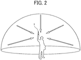
- FIG. 2 illustrates an example of how a user uses the image capturing device 1.
- the image capturing device 1 is used for capturing objects surrounding the user who is holding the image capturing device 1 in his/her hand.
- the imaging elements 103a and 103b illustrated in FIGs.1A to 1C capture the objects surrounding the user to obtain two hemispherical images.
- FIG. 3A is a view illustrating a hemispherical image (front side) captured by the image capturing device 1.
- FIG. 3B is a view illustrating a hemispherical image (back side) captured by the image capturing device 1.
- FIG. 3C is a view illustrating an image represented by Mercator projection. The image represented by Mercator projection as illustrated in FIG. 3C is referred to as a "Mercator image” hereinafter.
- FIG. 4A illustrates an example of how the Mercator image covers a surface of a sphere.
- FIG. 4B is a view illustrating the full spherical panoramic image.
- an image captured by the imaging element 103a is a curved hemispherical image (front side) taken through the fisheye lens 102a described later.
- an image captured by the imaging element 103b is a curved hemispherical image (back side) taken through the fisheye lens 102b described later.
- the hemispherical image (front side) and the hemispherical image (back side), which is reversed by 180-degree from each other, is combined by the image capturing device 1.
- the Mercator image as illustrated in FIG. 3C is generated.
- the Mercator image is pasted on the sphere surface using Open Graphics Library for Embedded Systems (OpenGL ES) as illustrated in FIG. 4A .
- OpenGL ES Open Graphics Library for Embedded Systems
- FIG. 4B the full spherical panoramic image as illustrated in FIG. 4B is generated.
- the full spherical panoramic image is represented as the Mercator image facing toward a center of the sphere.
- OpenGL ES is a graphic library used for visualizing two-dimensional (2D) and three-dimensional (3D) data.
- the full spherical panoramic image is either a still image or a movie.
- predetermined-area image a description is given of displaying the predetermined-area image with reference to FIG. 5 and FIGs. 6A and 6B .
- FIG. 5 is a view illustrating positions of a virtual camera IC and a predetermined area T in a case in which the full spherical panoramic image is represented as a three-dimensional solid sphere.
- the virtual camera IC corresponds to a position of a point of view (viewpoint) of a user who is viewing the full spherical panoramic image represented as the three-dimensional solid sphere.
- FIG. 6A is a perspective view of FIG. 5 .
- FIG. 6B is a view illustrating the predetermined-area image displayed on a display.
- the full spherical panoramic image illustrated in FIG. 4B is represented as a three-dimensional solid sphere CS.
- the predetermined area T in the full spherical panoramic image is an imaging area of the virtual camera IC.
- the predetermined area T is specified by predetermined-area information indicating a position coordinate (x(rH), y(rV), angle of view ⁇ (angle)) including an angle of view of the virtual camera IC in a three-dimensional virtual space containing the full spherical panoramic image.
- Zooming of the predetermined area T is implemented by enlarging or reducing a range (arc) of the angle of view ⁇ . Further, zooming of the predetermined area T is implemented by moving the virtual camera IC toward or away from the full spherical panoramic image.
- the predetermined-area image which is an image of the predetermined area T illustrated in FIG. 6A , is displayed as an imaging area of the virtual camera IC, as illustrated in FIG. 6B.
- FIG. 6B illustrates the predetermined-area image represented by the predetermined-area information that is set by default.
- the predetermined-area image may be specified by an imaging area (X, Y, Z) of the virtual camera IC, i.e., the predetermined area T, rather than the predetermined-area information, i.e., the position coordinate of the virtual camera IC.
- a description is given hereinafter using the position coordinate (x(rH), y(rV), and an angle of view ⁇ (angle)) of the virtual camera IC.
- FIG. 7 is a view illustrating a relation between the predetermined-area information and the predetermined area T.
- a center point CP of 2L provides the parameters (x, y) of the predetermined-area information, where 2L denotes a diagonal angle of view of the predetermined area T specified the angle of view ⁇ of the virtual camera IC.
- f is the distance from the virtual camera IC to the center point CP.
- L is a distance between the center point CP and a given vertex of the predetermined area T (2L is a diagonal line).
- a trigonometric function equation generally expressed by the following equation (1) is satisfied.
- L / f tan ⁇ / 2
- FIG. 8 is a schematic diagram illustrating a configuration of the image communication system according to this embodiment.
- the image communication system includes an image capturing device 1a, an image capturing device 1b, a videoconference terminal 3a, a videoconference terminal 3d, a display 4a, a display 4d, a communication management system 5, a personal computer (PC) 7, an image capturing device 8, and a smartphone 9.
- the videoconference terminal 3a, the smartphone 9, the PC 7, and the videoconference terminal 3d communicate data with one another via a communication network 100 such as the Internet.
- the communication network 100 may be either a wireless network or a wired network.
- the image capturing device 1a and the image capturing device 1b are each a special digital camera, which captures an image of a subject or surroundings to obtain two hemispherical images, from which a full spherical panoramic image is generated, as described above.
- the image capturing device 8 is a general-purpose digital camera that captures an image of a subject or surroundings to obtain a general planar image.
- the videoconference terminals 3a and the videoconference terminal 3d are each a terminal dedicated to videoconferencing.
- the videoconference terminal 3a and the videoconference terminal 3d display an image of video calling on the displays 4a and 4d, respectively, via a wired cable such as a universal serial bus (USB).
- the videoconference terminal 3a usually captures an image by a camera 312, which is described later.
- the image capturing device 1a is preferentially used. Accordingly, two hemispherical images are obtained, from which a full spherical panoramic image is generated.
- the cradle 2a When a wired cable is used for connecting the videoconference terminal 3a and the cradle 2a, the cradle 2a not only enables communications between the image capturing device 1a and the videoconference terminal 3a but also supplies power with the image capturing device 1a and holds the image capturing device 1a.
- the image capturing device 1a, the cradle 2a, the videoconference terminal 3a, and the display 4a are located at the same site A. In the site A, four users A1, A2, A3 and A4 are participating in video calling.
- the videoconference terminal 3d and the display 4d are located at the same site D. In the site D, three users D1, D2, and D3 are participating in video calling.
- the communication management system 5 manages and controls communication of the videoconference terminal 3a, the videoconference terminal 3d, the PC 7 and the smartphone 9. Further, the communication management system 5 manages types (a general image type and a special image type) of image data exchanged. Therefore, the communication management system 5 also operates as a communication control system. In this disclosure, the special image is a full spherical panoramic image.
- the communication management system 5 is located, for example, at a service provider that provides video communication service. In one example, the communication management system 5 is configured as a single computer. In another example, the communication management system 5 is constituted as a plurality of computers to which divided portions (functions, means, or storages) are arbitrarily allocated. In other words, the communication management system 5 may be implemented by a plurality of servers that operate in cooperation with one another.
- the PC 7 performs video calling with the image capturing device 8 connected thereto.
- the PC 7 and the image capturing device 8 are located at the same site C. At the site C, one user C is participating in video calling.
- the smartphone 9 includes a display 917, which is described later, and displays an image of video calling on the display 917.
- the smartphone 9 includes a complementary metal oxide semiconductor (CMOS) sensor 905, and usually captures an image with the CMOS sensor 905.
- the smartphone 9 is also capable of obtaining data of two hemispherical images captured by the image capturing device 1b, based on which the full spherical panoramic image is generated, by wireless communication such as Wireless Fidelity (Wi-Fi) and Bluetooth (registered trademark).
- Wi-Fi Wireless Fidelity
- Bluetooth registered trademark
- a cradle 2b just supplies power with the image capturing device 1b and holds the image capturing device 1b.
- the image capturing device 1b, the cradle 2b, and the smartphone 9 are located at the same site B. Further, in the site B, two users B1 and B2 are participating in video calling.
- the videoconference terminal 3a, the videoconference terminal 3d, the PC 7 and the smartphone 9 are each an example of a communication terminal.
- OpenGL ES is installed in each of those communication terminals to enable each communication terminal to generate predetermined-area information that indicates a partial area of a full spherical panoramic image, or to generate a predetermined-area image from a full spherical panoramic image that is transmitted from a different communication terminal.
- FIG. 8 The arrangement of the terminals, apparatuses and users illustrated in FIG. 8 is just an example, and any other suitable arrangement will suffice.
- an image capturing device that is capable of performing image capturing for a full spherical panoramic image may be used in place of the image capturing device 8.
- examples of the communication terminal include a digital television, a smartwatch, and a car navigation device.
- image capturing device 1 any arbitrary one of the image capturing device 1a and the image capturing device 1b is referred to as "image capturing device 1".
- any arbitrary one of the videoconference terminal 3a and the videoconference terminal 3d is referred to as "videoconference terminal 3", hereinafter.
- any arbitrary one of the display 4a and the display 4d is referred to as "display 4", hereinafter.
- FIG. 9 is a block diagram illustrating a hardware configuration of the image capturing device 1.
- the image capturing device 1 is a full spherical (omnidirectional) image capturing device having two imaging elements.
- the image capturing device 1 may include any suitable number of imaging elements, providing that it includes at least two imaging elements.
- the image capturing device 1 is not necessarily an image capturing device dedicated to omnidirectional image capturing.
- an external omnidirectional image capturing unit may be attached to a general-purpose digital camera or a smartphone to implement an image capturing device having substantially the same function as that of the image capturing device 1.
- the image capturing device 1 includes an imaging unit 101, an image processing unit 104, an imaging control unit 105, a microphone 108, an audio processing unit 109, a central processing unit (CPU) 111, a read only memory (ROM) 112, a static random access memory (SRAM) 113, a dynamic random access memory (DRAM) 114, an operation unit 115, a network interface (I/F) 116, a communication device 117, and an antenna 117a.
- CPU central processing unit
- ROM read only memory
- SRAM static random access memory
- DRAM dynamic random access memory
- I/F network interface
- the imaging unit 101 includes two wide-angle lenses (so-called fish-eye lenses) 102a and 102b, each having an angle of view of equal to or greater than 180 degrees so as to form a hemispherical image.
- the imaging unit 101 further includes the two imaging elements 103a and 103b corresponding to the wide-angle lenses 102a and 102b respectively.
- the imaging elements 103a and 103b each includes an image sensor such as a CMOS sensor and a charge-coupled device (CCD) sensor, a timing generation circuit, and a group of registers.
- the image sensor converts an optical image formed by the fisheye lenses 102a and 102b into electric signals to output image data.
- the timing generation circuit generates horizontal or vertical synchronization signals, pixel clocks and the like for the image sensor.
- Various commands, parameters and the like for operations of the imaging elements 103a and 103b are set in the group of registers.
- Each of the imaging elements 103a and 103b of the imaging unit 101 is connected to the image processing unit 104 via a parallel I/F bus.
- each of the imaging elements 103a and 103b of the imaging unit 101 is connected to the imaging control unit 105 via a serial I/F bus such as an I2C bus.
- the image processing unit 104 and the imaging control unit 105 are each connected to the CPU 111 via a bus 110.
- the ROM 112, the SRAM 113, the DRAM 114, the operation unit 115, the network I/F 116, the communication device 117, and the electronic compass 118 are also connected to the bus 110.
- the image processing unit 104 acquires image data from each of the imaging elements 103a and 103b via the parallel I/F bus and performs predetermined processing on each image data. Thereafter, the image processing unit 104 combines these image data to generate data of the Mercator image as illustrated in FIG. 3C .
- the imaging control unit 105 usually functions as a master device while the imaging elements 103a and 103b each usually functions as a slave device.
- the imaging control unit 105 sets commands and the like in the group of registers of the imaging elements 103a and 103b via the I2C bus.
- the imaging control unit 105 receives necessary commands from the CPU 111. Further, the imaging control unit 105 acquires status data of the group of registers of the imaging elements 103a and 103b via the I2C bus.
- the imaging control unit 105 sends the acquired status data to the CPU 111.
- the imaging control unit 105 instructs the imaging elements 103a and 103b to output the image data at a time when the shutter button of the operation unit 115 is pressed.
- the image capturing device 1 may display a preview image on a display (e.g., a display of the videoconference terminal 3a) or may support displaying movie. In this case, the image data are continuously output from the imaging elements 103a and 103b at a predetermined frame rate (frames per minute).
- the imaging control unit 105 operates in cooperation with the CPU 111 to synchronize times when the imaging elements 103a and 103b output the image data. It should be noted that although in this embodiment, the image capturing device 1 does not include a display unit (display), the image capturing device 1 may include the display.
- the microphone 108 converts sounds to audio data (signal).
- the audio processing unit 109 acquires the audio data from the microphone 108 via an I/F bus and performs predetermined processing on the audio data.
- the CPU 111 controls an entire operation of the image capturing device 1 and performs necessary processing.
- the ROM 112 stores various programs for the CPU 111.
- the SRAM 113 and the DRAM 114 each operates as a work memory to store programs loaded from the ROM 112 for execution by the CPU 111 or data in current processing. More specifically, the DRAM 114 stores image data currently processed by the image processing unit 104 and data of the Mercator image on which processing has been performed.
- the operation unit 115 collectively refers to various operation keys, a power switch, the shutter button, and a touch panel having functions of both displaying information and receiving input from a user, which may be used in combination.
- the user operates the operation keys to input various photographing modes or photographing conditions.
- the network I/F 116 collectively refers to an interface circuit such as a USB I/F that allows the image capturing device 1 to communicate data with an external media such as an SD card or an external personal computer.
- the network I/F 116 supports at least one of wired and wireless communications.
- the data of the Mercator image which is stored in the DRAM 114, is stored in the external media via the network I/F 116 or transmitted to the external device such as the videoconference terminal 3a via the network I/F 116, as needed.
- the communication device 117 communicates data with an external device such as the videoconference terminal 3a via the antenna 117a of the image capturing device 1 by near distance wireless communication such as Wi-Fi and Near Field Communication (NFC).
- the communication device 117 is also capable of transmitting the data of Mercator image to the external device such as the videoconference terminal 3a.
- the electronic compass 118 calculates an orientation and a tilt (roll angle) of the image capturing device 1 from the Earth's magnetism to output orientation and tilt information.
- This orientation and tilt information is an example of related information, which is metadata described in compliance with Exif. This information is used for image processing such as image correction of captured images. Further, the related information also includes a date and time when the image is captured by the image capturing device 1, and a size of the image data.
- FIG. 10 is a block diagram illustrating a hardware configuration of the videoconference terminal 3.
- the videoconference terminal 3 includes a CPU 301, a ROM 302, a RAM 303, a flash memory 304, a solid state drive (SSD) 305, a medium I/F 307, an operation key 308, a power switch 309, a bus line 310, a network I/F 311, a camera 312, an imaging element I/F 313, a microphone 314, a speaker 315, an audio input/output interface 316, a display I/F 317, an external device connection I/F 318, a near-distance communication circuit 319, and an antenna 319a for the near-distance communication circuit 319.
- SSD solid state drive
- the CPU 301 controls an entire operation of the videoconference terminal 3.
- the ROM 302 stores a control program for operating the CPU 301 such as an Initial Program Loader (IPL).
- the RAM 303 is used as a work area for the CPU 301.
- the flash memory 304 stores various data such as a communication control program, image data, and audio data.
- the SSD 305 controls reading or writing of various data to and from the flash memory 304 under control of the CPU 301.
- a hard disk drive (HDD) may be used in place of the SSD 305.
- the medium I/F 307 controls reading or writing (storing) of data with respect to a recording medium 306 such as a flash memory.
- the operation key 308 is operated by a user to input a user instruction such as a user selection of a destination of the videoconference terminal 3.
- the power switch 309 is a switch that turns on or off the power of the videoconference terminal 3.
- the network I/F 311 allows communication of data with an external device through the communication network 100 such as the Internet.
- the camera 312 is an example of a built-in imaging device capable of capturing a subject under control of the CPU 301 to obtain image data.
- the imaging element I/F 313 is a circuit that controls driving of the camera 312.
- the microphone 314 is an example of a built-in audio collecting device capable of inputting audio.
- the audio input/output interface 316 is a circuit for controlling input and output of audio signals between the microphone 314 and the speaker 315 under control of the CPU 301.
- the display I/F 317 is a circuit for transmitting image data to an external display 4 under control of the CPU 301.
- the external device connection I/F 318 is an interface circuit that connects the videoconference terminal 3 to various external devices.
- the near-distance communication circuit 319 is a communication circuit that communicates in compliance with the NFC (registered trademark), the Bluetooth (registered trademark) and the like.
- the bus line 310 may be an address bus or a data bus, which electrically connects various elements such as the CPU 301 illustrated in FIG. 10 .
- the display 4 is an example of a display unit, such as a liquid crystal or organic electroluminescence (EL) display that displays an image of a subject, an operation icon, or the like.
- the display 4 is connected to the display I/F 317 by a cable 4c.
- the cable 4c may be an analog red green blue (RGB) (video graphic array (VGA)) signal cable, a component video cable, a high-definition multimedia interface (HDMI) (registered trademark) signal cable, or a digital video interactive (DVI) signal cable.
- RGB red green blue
- VGA video graphic array
- HDMI high-definition multimedia interface
- DVI digital video interactive
- the camera 312 includes a lens and a solid-state imaging element that converts an image (video) of a subject to electronic data through photoelectric conversion.
- the solid-state imaging element for example, a CMOS sensor or a CCD sensor is used.
- the external device connection I/F 318 is capable of connecting an external device such as an external camera, an external microphone, or an external speaker through a USB cable or the like.
- an external camera is connected, the external camera is driven in preference to the built-in camera 312 under control of the CPU 301.
- the external microphone or the external speaker is driven in preference to the built-in microphone 314 or the built-in speaker315 under control of the CPU 301.
- the recording medium 306 is removable from the videoconference terminal 3.
- any suitable nonvolatile memory such as an electrically erasable and programmable ROM (EEPROM), may be used, provided that it reads or writes data under control of CPU 301.
- EEPROM electrically erasable and programmable ROM
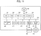
- FIG. 11 is a block diagram illustrating a hardware configuration of any one of the communication management system 5 and the PC 7.
- both the communication management system 5 and the PC 7 are implemented by a computer. Therefore, a description is given of a configuration of the communication management system 5, and the description of a configuration of the PC 7 is omitted, having the same or substantially the same configuration as that of the communication management system 5.
- the communication management system 5 includes a CPU 501, a ROM 502, a RAM 503, an HD 504, a hard disc drive (HDD) 505, a media drive 507, a display 508, a network I/F 509, a keyboard 511, a mouse 512, a compact disc rewritable (CD-RW) drive 514, and a bus line 510.
- the CPU 501 controls entire operation of the communication management system 5.
- the ROM 502 stores programs such as an IPL to boot the CPU 501.
- the RAM 503 is used as a work area for the CPU 501.
- the HD 504 stores various data such as programs for the communication management system 5.
- the HDD 505 controls reading and writing of data from and to the HD 504 under control of the CPU 501.
- the media drive 507 controls reading and writing (storing) of data from and to a recording medium 506 such as a flash memory.
- the display 508 displays various information such as a cursor, menus, windows, characters, or images.
- the network I/F 509 enables communication of data with an external device through the communication network 100.
- the keyboard 511 includes a plurality of keys to allow a user to input characters, numbers, and various instructions.
- the mouse 512 allows a user to input an instruction for selecting and executing various functions, selecting an item to be processed, or moving the cursor.
- the CD-RW drive 514 controls reading or writing of data from or to a removable recording medium 513 such as a CD-RW or CD-ROM.
- the bus line 510 electrically connects those parts or devices of the communication management system 5 to each other as illustrated in FIG. 11 . Examples of the bus line 510 include an address bus and a data bus.
- FIG. 12 is a block diagram illustrating a hardware configuration of the smartphone 9.
- the smartphone 9 includes a CPU 901, a ROM 902, a RAM 903, an EEPROM 904, a CMOS sensor 905, an acceleration and orientation sensor 906, a medium I/F 908, and a global positioning system (GPS) receiver 909.
- a CPU 901 a ROM 902, a RAM 903, an EEPROM 904, a CMOS sensor 905, an acceleration and orientation sensor 906, a medium I/F 908, and a global positioning system (GPS) receiver 909.
- GPS global positioning system
- the CPU 901 controls an entire operation of the smartphone 9.
- the ROM 902 stores programs such as an IPL to boot the CPU 901.
- the RAM 903 is used as a work area for the CPU 901.
- the EEPROM 904 reads or writes various data such as a control program for the smartphone 9 under control of the CPU 901.
- the CMOS sensor 905 captures an object (mainly, a user operating the smartphone 9) under control of the CPU 901 to obtain image data.
- the acceleration and orientation sensor 906 includes various sensors such as an electromagnetic compass for detecting geomagnetism, a gyrocompass, or an acceleration sensor.
- the medium I/F 908 controls reading or writing of data with respect to a recording medium 907 such as a flash memory.
- the GPS receiver 909 receives a GPS signal from a GPS satellite.
- the smartphone 9 further includes a far-distance communication circuit 911, a camera 912, an imaging element I/F 913, a microphone 914, a speaker 915, an audio input/output interface 916, a display 917, an external device connection I/F 918, a near-distance communication circuit 919, an antenna 919a for the near-distance communication circuit 919, and a touch panel 921.
- a far-distance communication circuit 911 a camera 912, an imaging element I/F 913, a microphone 914, a speaker 915, an audio input/output interface 916, a display 917, an external device connection I/F 918, a near-distance communication circuit 919, an antenna 919a for the near-distance communication circuit 919, and a touch panel 921.
- the far-distance communication circuit 911 is a circuit that communicates with other device through the communication network 100.
- the camera 912 is an example of a built-in imaging device capable of capturing a subject under control of the CPU 901 to obtain image data.
- the imaging element I/F 913 is a circuit that controls driving of the camera 912.
- the microphone 914 is an example of a built-in audio collecting device capable of inputting audio.
- the audio input/output interface 916 is a circuit for controlling input and output of audio signals between the microphone 914 and the speaker 915 under control of the CPU 901.
- the display 917 is an example of a display unit, such as a liquid crystal or organic electroluminescence (EL) display that displays an image of a subject, an operation icon, or the like.
- EL organic electroluminescence
- the external device connection I/F 918 is an interface circuit that connects the smartphone 9 to various external devices.
- the near-distance communication circuit 919 is a communication circuit that communicates in compliance with the NFC, the Bluetooth and the like.
- the touch panel 921 is an example of an input device to operate a smartphone 9 by touching a screen of the display 917.
- the smartphone 9 further includes a bus line 910.
- Examples of the bus line 910 include an address bus and a data bus, which electrically connects the elements such as the CPU 901.
- a recording medium such as a CD-ROM or a hard disk storing any one of the above-described programs may be distributed domestically or overseas as a program product.
- FIG. 13 and FIG. 14 are block diagrams, each illustrating a part of a functional configuration of the image communication system.
- the image capturing device 1a includes an acceptance unit 12a, an image capturing unit 13a, an audio collecting unit 14a, a communication unit 18a, and a data storage/read unit 19a. These units are functions or means that are implemented by or that are caused to function by operating any of the elements illustrated in FIG. 9 in cooperation with the instructions of the CPU 111 according to the image capturing device control program expanded from the SRAM 113 to the DRAM 114.
- the image capturing device 1a further includes a memory 1000a, which is implemented by the ROM 112, the SRAM 113, and the DRAM 114 illustrated in FIG. 9 .
- the memory 1000a stores therein a globally unique identifier (GUID) identifying the own device (i.e., the image capturing device 1a).
- GUID globally unique identifier
- the image capturing device 1b includes an acceptance unit 12b, an image capturing unit 13b, an audio collecting unit 14b, a communication unit 18b, a data storage/read unit 19b, and a memory 1000b. These functional units of the image capturing device 1b implement the similar or substantially the similar functions as those of the acceptance unit 12a, the image capturing unit 13a, the audio collecting unit 14a, the communication unit 18a, the data storage/read unit 19a, and the memory 1000 of the image capturing device 1a, respectively. Therefore, redundant descriptions thereof are omitted below.
- the acceptance unit 12a of the image capturing device 1a is implemented by the operation unit 115 illustrated in FIG. 9 , when operating under control of the CPU 111.
- the acceptance unit 12a receives an instruction input from the operation unit 115 according to a user operation.
- the image capturing unit 13a is implemented by the imaging unit 101, the image processing unit 104, and the imaging control unit 105, illustrated in FIG. 9 , when operating under control of the CPU 111.
- the image capturing unit 13a captures an image of a subject or surroundings to obtain captured-image data.
- the audio collecting unit 14a is implemented by the microphone 108 and the audio processing unit 109 illustrated in FIG. 9 , when operating under control of the CPU 111.
- the audio collecting unit 14a collects sounds around the image capturing device 1a.
- the communication unit 18a which is implemented by instructions of the CPU 111, communicates data with a communication unit 38 of the videoconference terminal 3a using the near-distance wireless communication technology in compliance with such as NFC, Bluetooth, or Wi-Fi.
- the data storage/read unit 19a which is implemented by instructions of the CPU 111 illustrated in FIG. 9 , stores data or information in the memory 1000a or reads out data or information from the memory 1000a.
- the videoconference terminal 3a includes a data exchange unit 31a, an acceptance unit 32a, an image and audio processor 33a, a display control 34a, a determination unit 35a, a generator 36a, a change unit 37a, a communication unit 38a, and a data storage/read unit 39a.
- These units are functions that are implemented by or that are caused to function by operating any of the elements illustrated in FIG. 10 in cooperation with the instructions of the CPU 301 according to the control program for the videoconference terminal 3a, expanded from the flash memory 304 to the RAM 303.
- the videoconference terminal 3a further includes a memory 3000a, which is implemented by the ROM 302, the RAM 303, and the flash memory 304 illustrated in FIG. 10 .
- the memory 3000a stores an image type management DB 3001a, an image capturing device management DB 3002a, a display layout management DB 3003a, and a required resolution management DB 3004a.
- the image type management DB 3001a is implemented by an image type management table illustrated in FIG. 15 .
- the image capturing device management DB 3002a is implemented by an image capturing device management table illustrated in FIG. 16 .
- the display layout management DB 3003a is implemented by a display layout management table illustrated in FIG. 17A .
- the required resolution management DB 3004a is implemented by required resolution management tables illustrated in FIGs. 18A and 18B .
- the videoconference terminal 3d includes a data exchange unit 31d, an acceptance unit 32d, an image and audio processor 33d, a display control 34d, a determination unit 35d, a generator 36d, a change unit 37d, a communication unit 38d, and a data storage/read unit 39d, and a memory 3000d.
- These functional units of the videoconference terminal 3d implement the similar or substantially the similar functions as those of the data exchange unit 31a, the acceptance unit 32a, the image and audio processor 33a, the display control 34a, the determination unit 35a, the generator 36a, the change unit 37a, the communication unit 38a, the data storage/read unit 39a, and the memory 3000a of the videoconference terminal 3a, respectively. Therefore, redundant descriptions thereof are omitted below.
- the memory 3000d of the videoconference terminal 3d stores an image type management DB 3001d, and an image capturing device management DB 3002d, a display layout management DB 3003d, and a required resolution management DB 3004d.
- These DBs 3001d, 3002d, 3003d and 3004d have the same or the substantially the same data structure as the image type management DB 3001a, the image capturing device management DB 3002a, the display layout management DB 3003a, and the required resolution management DB 3004a of the videoconference terminal 3a, respectively. Therefore, redundant descriptions thereof are omitted below.
- FIG. 15 is a conceptual diagram illustrating the image type management table according to an embodiment of this disclosure.
- the image type management table stores an image data identifier (ID), an IP address, which is an example of an address of a sender terminal, and a source name, in association with one another.
- the image data ID is one example of image data identification information for identifying image data to be used in video communication.
- An identical image data ID is assigned to image data transmitted from the same sender terminal. Accordingly, a destination terminal (that is, a communication terminal that receives image data) can identify a sender terminal from which the image data is received.
- the IP address of the sender terminal which is associated with specific image data ID, is an IP address of a communication terminal that transmits image data identified by that image data ID associated with the IP address.
- the source name which is associated with specific image data ID, is a name for identifying an image capturing device that outputs the image data identified by that image data ID associated with the source name.
- the source name is one example of image type information. This source name is generated by a communication terminal such as the videoconference terminal 3a according to a predetermined naming rule.
- the example of the image type management table illustrated in FIG. 15 indicates that four communication terminals, whose IP addresses are respectively "1.2.1.3”, “1.2.2.3”, “1.3.1.3”, and “1.3.2.3” transmit image data identified by the image data ID "RS001", "RS002", “RS003", and "RS004", respectively.
- the image types represented by the source names of those four communication terminals are "Video_Theta”, “Video_Theta”, “Video”, and “Video”, which indicate that the image types are the special image, special image, general image, and general image, respectively.
- the special image is a full spherical panoramic image
- the general image is a planar image.
- information regarding data other than the image data may be stored in the image type management table in association with the image data ID.
- Examples of the data other than the image data include audio data and presentation material data shared on a screen, for example, in video communication in which the image is shared.
- information regarding data other than the image data may be stored in the image type management table in association with the image data ID.
- Examples of the data other than the image data include audio data and presentation material data shared on a screen, for example, in video communication in which the image is shared.
- FIG. 16 is a conceptual diagram illustrating the image capturing device management table according to an embodiment of this disclosure.
- the image capturing device management table stores a vendor ID and a product ID from among the GUIDs of an image capturing device that is capable of obtaining two hemispherical images, from which a full spherical panoramic image is generated.
- a vendor ID VID
- a product ID PID
- Those vendor ID and product ID are stored in a communication terminal such as a videoconference terminal before shipment. In another example, those IDs are added and stored in the videoconference terminal after shipment.
- FIGs. 17A, 17B, 17C and 17D are conceptual diagrams, each illustrating the display layout management table.
- FIG. 17A illustrates a data structure of the display layout management DB 3003a stored in the memory 3000a in the videoconference terminal 3a.
- FIG. 17B illustrates a data structure of a display layout management DB 9003 stored in the memory 9000 of the smartphone 9.
- FIG. 17C illustrates a data structure of a display layout management DB 7003 stored in the memory 7000 of the PC 7.
- FIG. 17D illustrates a data structure of the display layout management DB 3003d stored in the memory 3000d of the videoconference terminal 3d.
- the display layout management table illustrated in FIG. 17A stores, for each layout number indicating a layout of the plurality of display areas on the display 4a, an image data ID for identifying image data of an image to be displayed in the display area according to the layout, and a display size (number of pixels in horizontal and vertical directions) of the display area.
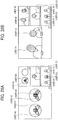
- the layout number in this table specifies one of a plurality of display areas in which the image data is to be displayed. More specifically, the layout number in this example corresponds to a number indicated at the lower right corner of each display area as illustrated in FIGs. 28A and 28B .
- the display size is information acquired from the display 4a by the videoconference terminal 3a. Accordingly, when the display 4a to be used is changed, the display size in the display layout management table is also changed.
- the image data IDs in the display layout management table are also changed (switched).
- FIG. 28B when the user B1 starts to speak, an image of the site B that was displayed in a display area "2" is switched to be displayed in a display area "1", and an image of the site A that was displayed in the display area "1" is switched to be displayed in the display area "2".
- This change is performed by the change unit 37a based on audio data and the image data ID.
- FIGs. 18A and 18B are conceptual diagrams illustrating the required resolution management tables for the different image types.
- the required resolution management tables of FIGs. 18A and 18B store, for respective ones of image type information indicating the different image types, the display size (number of pixels in horizontal and vertical directions) of each of the plurality of display areas of the display, in association with a required resolution (number of pixels in the horizontal and vertical directions) of image data to be requested for the communication management system 5.
- FIG. 18A is an example of the required resolution management table for the special image as the image type information.
- FIG. 18B illustrates an example of the required resolution management table for the general image as the image type information. As seen from FIGs.
- the required resolution (640 ⁇ 480 pixels) for the special image is higher than the required resolution (1280 ⁇ 720 pixels) for the general image.
- FIG. 6B is an image of a predetermined area T as a partial area of the full spherical panoramic image, as illustrated in FIG. 6A . Accordingly, the predetermined-area image is made suitable for viewing.
- the data exchange unit 31a of the videoconference terminal 3a is implemented by the network I/F 311 illustrated in FIG. 10 , when operating under control of the CPU 301.
- the data exchange unit 31a exchanges data or information with communication management system 5 via the communication network 100.
- the acceptance unit 32a is implemented by the operation key 308, when operating under control of the CPU 301.
- the acceptance unit 32a receives selections or inputs from a user.
- An input device such as a touch panel may be used as an alternative to or in place of the operation key 308.
- the image and audio processor 33a which is implemented by instructions of the CPU 301 illustrated in FIG. 10 , processes image data that is obtained by capturing a subject by the camera 312. In addition, after the audio of the user is converted to an audio signal by the microphone 314, the image and audio processor 33a processes audio data according to this audio signal.
- the image and audio processor 33a processes image data received from other communication terminal based on the image type information such as the source name, to enable the display control 34 to control the display 4 to display an image based on the processed image data. More specifically, when the image type information indicates a special image, the image and audio processor 33a converts the image data such as hemispherical image data as illustrated in FIGs. 3A and 3B into full spherical image data to generate full spherical panoramic image data as illustrated in FIG. 4B , and further generates a predetermined-area image as illustrated in FIG. 6B . Furthermore, the image and audio processor 33a outputs, to the speaker 315, an audio signal according to audio data that is received from the other communication terminal via the communication management system 5. The speaker 315 outputs audio based on the audio signal.
- the display control 34a is implemented by the display I/F 317, when operating under control of the CPU 301.
- the display control 34a controls the display 4 to display images or characters.
- the determination unit 35a which is implemented by instructions of the CPU 301, determines an image type according to the image data received from such as the image capturing device 1a.
- the generator 36a is implemented by instructions of the CPU 301.
- the generator 36a generates a source name, which is one example of the image type information, according to the above-described naming rule, based on a determination result generated by the determination unit 35a indicating a general image or a special image (that is, full spherical panoramic image in this disclosure). For example, when the determination unit 35a determines the image type as a general image, the generator 36a generates the source name "Video” indicating a general image. By contrast, when the determination unit 35a determines the image type as a special image, the generator 36a generates the source name "Video_Theta" indicating a special image.
- the change unit 37a which is implemented by instruction of the CPU 301, changes (switches) the image data IDs associated with the layout numbers in the display layout management table. More specifically, the change unit 37a changes association of a layout number with an image data ID, such that the image data ID transmitted from the site where a user who spoke immediately before is present is associated with the layout number "1". At the same time, the change unit 37a associates the image data ID that was associated with the layout number "1" before this change with a layout number that was associated with the image data ID transmitted from the site where the user who spoke immediately before is present. With this process by the change unit 37a, an image according to image data from a site where a user who spoke immediately before is present is constantly displayed the largest, as illustrated in FIG. 28B .
- the communication unit 38a is implemented by the near-distance communication circuit 319 and the antenna 319a, when operating under control of the CPU 301.
- the communication unit 38a communicates with the communication unit 18a of the image capturing device 1a using the near-distance communication technology in compliance with such as NFC, Bluetooth, or Wi-Fi.
- the communication unit 38a and the data exchange unit 31a have separate communication units, alternatively a shared communication unit may be used.
- the data storage/read unit 39a which is implemented by instructions of the CPU 301 illustrated in FIG. 10 , stores data or information in the memory 3000 or reads out data or information from the memory 3000.
- the communication management system 5 includes a data exchange unit 51, a resolution controller 53, a determination unit 55, a generator 56, and a data storage/read unit 59. These units are functions that are implemented by or that are caused to function by operating any of the elements illustrated in FIG. 11 in cooperation with the instructions of the CPU 501 according to the control program for the communication management system 5, expanded from the HD 504 to the RAM 503.
- the communication management system 5 further includes a memory 5000, which is implemented by the RAM 503 and the HD 504 illustrated in FIG. 11 .
- the memory 5000 stores a session management DB 5001, an image type management DB 5002, and a transmission resolution management DB 5003.
- the session management DB 5001 is implemented by a session management table illustrated in FIG. 19 .
- the image type management DB 5002 is implemented by an image type management table illustrated in FIG. 20 .
- the transmission resolution management DB 5003 is implemented by a transmission resolution management table illustrated in FIG. 21 .
- FIG. 19 is a conceptual diagram illustrating the session management table according to an embodiment of this disclosure.
- the session management table stores a session ID and an IP address of participating communication terminal, in association with each other.
- the session ID is one example of session identification information for identifying a session that implements video calling.
- the session ID is generated for each virtual conference room.
- the session ID is also stored in each communication terminal such as the videoconference terminal 3a.
- Each communication terminal selects a desired session ID from the session ID or IDs stored therein.
- the IP address of participating communication terminal indicates an IP address of the communication terminal participating in a virtual conference room identified by the associated session ID.
- FIG. 20 is a conceptual diagram illustrating the image type management table according to an embodiment of this disclosure.
- the image type management table illustrated in FIG. 20 stores, in addition to the information items stored in the image type management table illustrated in FIG. 15 , the same session ID as the session ID stored in the session management table, in association with one another.
- the example of the image type management table illustrated in FIG. 20 indicates that three communication terminals whose IP addresses are respectively "1.2.1.3", “1.2.2.3”, and "1.3.1.3" are participating in the virtual conference room identified by the session ID "se101".
- the communication management system 5 stores the same image data ID, IP address of the sender terminal, and image type information as those stored in a communication terminal such as the videoconference terminal 3a in order to transmit such information as the image type information to both a communication terminal that is already in video calling and a newly participating communication terminal that enters the virtual conference room after the video calling has started. Accordingly, the communication terminal that is already in the video calling and the newly participating communication terminal do not have to exchange such information as the image type information with each other.
- FIG. 21 is a conceptual diagram illustrating the transmission resolution management table according to an embodiment of this disclosure.
- the transmission resolution management table stores an IP address of a destination (a required resolution sender terminal) to which image data is to be transmitted in a column direction in association with an IP address of an image data sender terminal from which image data is received in a row direction. Based on this table, when relaying image data received from the site A (videoconference terminal 3a) to the site D (videoconference terminal 3d) for example, the communication management system 5 transmits the image data having the resolution of 1280 ⁇ 720 pixels to the site D.
- the data exchange unit 51 of the communication management system 5 is implemented by the network I/F 509 illustrated in FIG. 11 , when operating under control of the CPU 501.
- the data exchange unit 51 exchanges data or information with the videoconference terminal 3a, the videoconference terminal 3d, or the PC 7 via the communication network 100.
- the resolution controller 53 which is implemented by instructions of the CPU 501, controls (for example, changes) the resolution of image data transmitted from one communication terminal, based on the transmission resolution management DB 5003.
- the determination unit 55 which is implemented by instructions of the CPU 501, performs various determinations.
- the generator 56 which is implemented by instructions of the CPU 501, generates the image data ID.
- the data storage/read unit 59 is implemented by the HDD 505 illustrated in FIG. 11 , when operating under control of the CPU 501.
- the data storage/read unit 59 stores data or information in the memory 5000 or reads out data or information from the memory 5000.
- the PC 7 has the same or substantially the same functions as those of the videoconference terminal 3a.
- the PC 7 includes a data exchange unit 71, an acceptance unit 72, an image and audio processor 73, a display control 74, a determination unit 75, a generator 76, a change unit 77, a communication unit 78, and a data storage/read unit 79.
- These units are functions that are implemented by or that are caused to function by operating any of the hardware elements illustrated in FIG. 11 in cooperation with the instructions of the CPU 501 according to the control program for the PC 7, expanded from the HD 504 to the RAM 503.
- the PC 7 further includes a memory 7000, which is implemented by the ROM 502, the RAM 503 and the HD 504 illustrated in FIG. 11 .
- the memory 7000 stores an image type management DB 7001, an image capturing device management DB 7002, a display layout management DB 7003, and a required resolution management DB 7004.
- These DBs 7001, 7002, 7003 and 7004 have the same or the substantially the same data structure as the image type management DB 3001a, the image capturing device management DB 3002a, the display layout management DB 3003a, and the required resolution management DB 3004a of the videoconference terminal 3a, respectively. Therefore, redundant descriptions thereof are omitted below.
- the acceptance unit 72 which is implemented by the keyboard 511 and the mouse 512, when operating under control of the CPU 501, implements the similar or substantially the similar function to that of the acceptance unit 32a.
- the image and audio processor 73 which is implemented by instructions of the CPU 501, implements the similar or substantially the similar function to that of the image and audio processor 33a.
- the display control 74 which is implemented by instructions of the CPU 501, implements the similar or substantially the similar function to that of the display control 34a.
- the determination unit 75 which is implemented by instructions of the CPU 501, implements the similar or substantially the similar function to that of the determination unit 35a.
- the generator 76 which is implemented by instructions of the CPU 501, implements the similar or substantially the similar function to that of the generator 36a.
- the change unit 77 which is implemented by instructions of the CPU 501, implements the similar or substantially the similar function to that of the change unit 37a.
- the communication unit 78 which is implemented by instructions of the CPU 501, implements the similar or substantially the similar function to that of the communication unit 38a.
- the data storage/read unit 79 which is implemented by instructions of the CPU 501, stores data or information in the memory 7000 or reads out data or information from the memory 7000.
- the smartphone 9 has the same or substantially the same functions as those of the videoconference terminal 3a.
- the smartphone 9 includes a data exchange unit 91, an acceptance unit 92, an image and audio processor 93, a display control 94, a determination unit 95, a generator 96, a change unit 97, a communication unit 98, and a data storage/read unit 99.
- These units are functions that are implemented by or that are caused to function by operating any of the hardware elements illustrated in FIG. 12 in cooperation with the instructions of the CPU 901 according to the control program for the smartphone 9 expanded from the EEPROM 904 to the RAM 903.
- the smartphone 9 further includes a memory 9000, which is implemented by the ROM 902, the RAM 903, and the EEPROM 904 illustrated in FIG. 12 .
- the memory 9000 stores an image type management DB 9001, an image capturing device management DB 9002, a display layout management DB 9003, and a required resolution management DB 9004.
- These DBs 9001, 9002, 9003 and 9004 have the same or the substantially the same data structure as the image type management DB 3001a, the image capturing device management DB 3002a, the display layout management DB 3003a, and the required resolution management DB 3004a of the videoconference terminal 3a, respectively. Therefore, redundant descriptions thereof are omitted below.
- the acceptance unit 92 which is implemented by the touch panel 921, when operating under control of the CPU 901, implements the similar or substantially the similar function to that of the acceptance unit 32a.
- the image and audio processor 93 which is implemented by instructions of the CPU 901, implements the similar or substantially the similar function to that of the image and audio processor 33 a.
- the display control 94 which is implemented by instructions of the CPU 901, implements the similar or substantially the similar function to that of the display control 34a.
- the determination unit 95 which is implemented by instructions of the CPU 901, implements the similar or substantially the similar function to that of the determination unit 35a.
- the generator 96 which is implemented by instructions of the CPU 901, implements the similar or substantially the similar function to that of the generator 36a.
- the change unit 97 which is implemented by instructions of the CPU 901, implements the similar or substantially the similar function to that of the change unit 37a.
- the communication unit 98 which is implemented by instructions of the CPU 901, implements the similar or substantially the similar function to that of the communication unit 38a.
- the data storage/read unit 99 which is implemented by instructions of the CPU 901, stores data or information in the memory 9000 or reads out data or information from the memory 9000.
- FIG. 22 is a sequence diagram illustrating an operation of participating in the specific communication session.
- FIG. 23 is a view illustrating a selection screen for accepting selection of a desired communication session (virtual conference).
- the acceptance unit 32a of the videoconference terminal 3a accepts an instruction to display the selection screen for the communication session (virtual conference room), which is input by a user (e.g., the user A1) at the site A.
- the display control 34a controls the display 4a to display the selection screen as illustrated in FIG. 23 (S21).
- the selection screen displays selection buttons b1, b2, and b3, which respectively represent virtual conference rooms R1, R2, R3, each being a selection target.
- Each of the selection buttons b1, b2, and b3 is associated with the session ID.
- the acceptance unit 32a accepts selection of a communication session (S22). Then, the data exchange unit 31a transmits a request for participating in a virtual conference room to the communication management system 5 (S23).
- This participation request includes the session ID identifying the communication session for which the selection is accepted at S22, and the IP address of the videoconference terminal 3a as a request sender terminal.
- the communication management system 5 receives the participation request at the data exchange unit 51.
- the data storage/read unit 99 performs a process for enabling the videoconference terminal 3a to participate in the communication session (S24). More specifically, in the session management DB 5001 ( FIG. 19 ), the data storage/read unit 99 adds the IP address that is received at S23 to a field of the participating terminal IP address in a record of the same session ID as the session ID that is received at S23.
- the data exchange unit 51 transmits a response to the participation request to the videoconference terminal 3a (S25). This response to the participation request includes the session ID that is received at S23, and a result of the participation process.
- the videoconference terminal 3a receives the response to the participation request at the data exchange unit 31a. The following describes a case in which the process for enabling the videoconference terminal 3a to participate in the communication session is successfully completed.
- FIG. 24 is a sequence diagram illustrating an operation of managing the image type information.
- the data storage/read unit 19a of the image capturing device 1a reads out the GUID of the own device (e.g., the image capturing device 1a) from the memory 1000a.
- the communication unit 18a transmits the own device's GUID to the communication unit 38a of the videoconference terminal 3 (S51).
- the videoconference terminal 3a receives the GUID of the image capturing device 1a at the communication unit 38a.
- the determination unit 35a of the videoconference terminal 3a determines whether the same vendor ID and product ID as those of the GUID received at S51 are stored in the image capturing device management DB 3002a ( FIG. 16 ) to determine the image type (S52). More specifically, the determination unit 35a determines that the image capturing device 1a is an image capturing device that captures a special image (a full spherical panoramic image, in this disclosure), based on determination that the same vender ID and product ID are stored in the image capturing device management DB 3002a. By contrast, the determination unit 35a determines that the image capturing device 1a is an image capturing device that captures a general image, based on determination that the same vender ID and product ID are not stored in the image capturing device management DB 3002a.
- the data storage/read unit 39a stores, in the image type management DB 3001a ( FIG. 15 ), the IP address of the own terminal (i.e., videoconference terminal 3a) as the sender terminal in association with the image type information, which is a determination result determined at S52 (S53).
- the image data ID is not yet associated.
- the image type information include the source name that is determined according to a predetermined naming rule, and the image type (general image or special image type).
- the data exchange unit 31a transmits a request for adding the image type information to the communication management system 5 (S54).
- This request for adding image type information includes the IP address of the own terminal as a sender terminal, and the image type information, both being stored at S53 in association with each other.
- the communication management system 5 receives the request for adding the image type information at the data exchange unit 51.
- the data storage/read unit 59 of the communication management system 5 searches the session management DB 5001 ( FIG. 19 ) using the IP address of the sender terminal received at S54 as a search key, to read out the session ID associated with the IP address (S55).
- the generator 56 generates a unique image data ID (S56).
- the data storage/read unit 59 stores, in the image type management DB 5002 ( FIG. 20 ), a new record associating the session ID that is read out at S55, the image data ID generated at S56, the IP address of the sender terminal and the image type information that are received at S54, with one another (S57).
- the data exchange unit 51 transmits the image data ID generated at S56 to the videoconference terminal 3a (S58).
- the videoconference terminal 3a receives the image data ID at the data exchange unit 31a.
- the data storage/read unit 39a of the videoconference terminal 3a stores, in the image type management DB 3001a ( FIG. 15 ), the image data ID received at S58, in association with the IP address of the own terminal (i.e., videoconference terminal 3a) as the sender terminal and the image type information that are stored at S53 (S59).
- the data exchange unit 51 of the communication management system 5 transmits a notification of addition of the image type information to other communication terminal (the videoconference terminal 3d, in this example) (S60).
- This notification of addition of the image type information includes the image data ID generated at S56, and the IP address of the own terminal (i.e., videoconference terminal 3a) as the sender terminal and the image type information that are stored at S53.
- the videoconference terminal 3d receives the notification of addition of the image type information at the data exchange unit 31a.
- the destination to which the data exchange unit 51 transmits the notification is other IP address that is associated with the same session ID as that associated with the IP address of the videoconference terminal 3a in the session management DB 5001 ( FIG. 19 ). In other words, the destination is other communication terminal that is in the same virtual conference room as the videoconference terminal 3a.
- the data storage/read unit 39d of the videoconference terminal 3d stores, in the image type management DB 3001d ( FIG. 15 ), a new record associating the image data ID, the IP address of the sender terminal, and the image type information, which are received at S60 (S61).
- the notification of addition of the image type information is transmitted to the PC 7 and the smartphone 9, each being other communication terminal.
- the PC 7 and the smartphone 9 each stores the image data ID, the IP address of the sender terminal, and the image type information, in corresponding one of the image type management DBs 7001 and 9001.
- the same information is shared among the communication terminals in the image type management DBs 3001a, 3001d, 7001 and 9001, respectively.
- FIG. 25 is a sequence diagram illustrating an operation of requesting the resolution.
- the data storage/read unit 39a of the videoconference terminal 3d reads out each information item of the image data ID and the display size from the display layout management DB 3003d ( FIG. 17D ) (S71). Then, the data storage/read unit 39a searches the image type management DB 3001d ( FIG. 15 ) using the image data ID that is read out at S71 as a search key, to read out the image type information associated with the image data ID (S72). Next, the data storage/read unit 39a selects the table of FIG. 18A or the table of FIG. 18B in the required resolution management DB 3004d based on the image type information that is read out at S72. Further, the data storage/read unit 39a searches the selected table using the display size that is read out at S71 as a search key to read out information indicating the required resolution associated with the display size (S73).
- the data exchange unit 31d of the videoconference terminal 3d transmits resolution request information indicating a request of the resolution to the communication management system 5 (S74).
- This resolution request information contains the image data ID that is read out at S71 and the required resolution that is read out at S73.
- the communication management system 5 receives the resolution request information at the data exchange unit 51.
- the data storage/read unit 59 of the communication management system 5 searches the image type management DB 5002 ( FIG. 20 ) using the image data ID received at S74 as a search key, to read out the IP address of the sender terminal associated with the image data ID (S75). Then, the data storage/read unit 59 stores the required resolution received at S75 in accordance with the IP address that is read out at S75 in the transmission resolution management DB 5003 (S76).
- FIG. 26 is a sequence diagram illustrating an image data transmission process in video calling.
- the communication unit 18a of the image capturing device 1a transmits image data and audio data obtained by capturing a subject or surroundings to the communication unit 38a of the videoconference terminal 3a (S101).
- the image capturing device 1a is a device that is capable of obtaining two hemispherical images from which a full spherical panoramic image is generated
- the image data is configured by data of the two hemispherical images as illustrated in FIGs. 3A and 3B .
- the videoconference terminal 3a receives the image data and the audio data at the communication unit 38a.
- the data exchange unit 31a of the videoconference terminal 3a transmits, to the communication management system 5, the image data and the audio data received from the image capturing device 1a (S102).
- This transmission includes an image data ID for identifying the image data as a transmission target.
- the communication management system 5 receives the image data and the image data ID at the data exchange unit 51.
- the resolution controller 53 performs control to change the resolution of the image data received at S102, based on the required resolution stored in the transmission resolution management DB 5003 (S103).
- the resolution controller 53 performs control not to change the resolution of the image data.
- the data exchange unit 51 of the communication management system 5 transmits, to the videoconference terminal 3d, the image data on which the control of resolution has been already performed at S103 and the audio data (S104).
- This transmission includes an image data ID for identifying the image data as a transmission target.
- the videoconference terminal 3d receives the image data, the image data ID, and the audio data at the data exchange unit 31d.
- the data storage/read unit 39d of the videoconference terminal 3d searches the image type management DB 3001d ( FIG. 15 ) using the image data ID received at S104 as a search key, to read out the image type information (source name) associated with the image data ID (S105).
- the image type information indicates a special image (full spherical panoramic image, in this disclosure), i.e., when the image type information is "Video_Theta”
- the image and audio processor 33d generates a full spherical panoramic image from the image data received at S104, and further generates a predetermined-area image (S106).
- the data storage/read unit 39d searches the display layout management DB 3003d ( FIG. 17D ) using the image data ID received at S104 as a search key to read out the layout number associated with the image data ID, thereby determining a display area for displaying an image relating to the image data received at S104 from the plurality of display areas of the display 4d (S107). Then, the display control 34d displays the predetermined-area image in the display area determined at S107 (S108).
- the image type information indicates a general image, i.e., when the image type information is "Video"
- the image and audio processor 33d does not generate a full spherical panoramic image from the image data received at S104. In this case, the display control 34d displays a general image.
- FIGs. 27A and 27B illustrate example states of video calling. More specifically, FIG. 27A illustrates a case in which the image capturing device 1a is not used, while FIG. 27B illustrates a case in which the image capturing device 1a is used.
- the videoconference terminal 3a has to be placed at the corner of a desk, so that the users A1 to A4 can be captured with the camera 312, because the angle of view is horizontally 125 degrees and vertically 70 degrees. This requires the users A1 to A4 to talk while looking in the direction of the videoconference terminal 3a. Further, because the user A1 to A4 look in the direction of the videoconference terminal 3a, the display 4a has also to be placed near the videoconference terminal 3a.
- the videoconference terminal 3 a and the display 4a can be placed relatively at the center of the desk, because the image capturing device 1a is capable of obtaining two hemispherical images from which a full spherical panoramic image is generated.
- This enables the users A1 to A4 to talk in a relatively small voice, because they are close to the microphone 314. Further, it gets easier for the users A1 to A4 to see contents displayed on the display 4a.
- FIGs. 28A and 28B are views, each illustrating a display example on the display 4a at the site D. More specifically, FIG. 28A is a view illustrating an example in which image data transmitted from respective ones of the image capturing device 1a (videoconference terminal 3a) and the image capturing device 1b (smartphone 9) are displayed as they are, that is, without generating a full spherical panoramic image and a predetermined-area image.
- FIG. 28A is a view illustrating an example in which image data transmitted from respective ones of the image capturing device 1a (videoconference terminal 3a) and the image capturing device 1b (smartphone 9) are displayed as they are, that is, without generating a full spherical panoramic image and a predetermined-area image.
- FIG. 28A is a view illustrating an example in which image data transmitted from respective ones of the image capturing device 1a (videoconference terminal 3a) and the image capturing device 1b (smartphone 9) are displayed as they are, that
- FIG. 28B is a view illustrating an example in which predetermined-area images are displayed, which are generated based on full spherical panoramic images generated from the image data transmitted from the image capturing device 1a (videoconference terminal 3a) and the image capturing device 1b (smartphone 9), respectively.
- an image of the site A is displayed in a left-side display area (layout number "1") of the display 4d.
- display number "2" an image of the site B is displayed.
- a middle-right display area (layout number "3") of the display 4d an image of the site C is displayed.
- a lower-right display area (layout number "4") an image of the site D (own site) is displayed.
- images are displayed as illustrated in FIG. 28A .
- the images of the site A and the site B are displayed as the front-side hemispherical image as illustrated in FIG. 3A and the backside hemispherical image as illustrated in FIG. 3B .
- the image and audio processor 33d when the image and audio processor 33d generates a full spherical panoramic image from the image data transmitted from respective ones of the image capturing device 1a (videoconference terminal 3a) and the image capturing device 1b (smartphone 9), each being capable of obtaining two hemispherical images from which the full spherical panoramic image is generated, and further generates a predetermined-area image, the predetermined-area image, which is a planar image, is displayed as illustrated in FIG. 28B . Further, in both of FIGs.
- the general image is displayed in the display areas of the site C and site D, because the image capturing device 8 and the camera 312 built in the videoconference terminal 3d, each being an image capturing device that obtains a general image, are used in the site C and the site D, respectively.
- a user is able to change a predetermined area for the predetermined-area image in the same full spherical panoramic image. More specifically, when the user D1, D2 or D3 operates the operation key 308 or moves his/her finger on the touch panel of the display 4d, the acceptance unit 32d detects an instruction for moving the image. The display control 34d shifts, rotates, reduces, or enlarges the predetermined-area image based on the instruction detected by the acceptance unit 32d.
- the communication terminal such as the videoconference terminal 3a generates a full spherical panoramic image, and further generates a predetermined-area image, depending on the image type information associated with the image data ID that is transmitted along with image data. This prevents the front side hemispherical image and the back side hemispherical image from being displayed as illustrated in FIG. 28A .
- the resolution of image data requested to the communication management system 5 is controlled depending on image types (S103). This prevents the resolution of an image displayed on a display from getting too low, and thereby preventing a user who views the image on the display from having difficulty in recognizing the surroundings or attendants of a communication counterpart.
- FIG. 29 is a sequence diagram illustrating another example of an operation of requesting the resolution.
- the data storage/read unit 39d reads out the image data ID and the display size from the display layout management DB 3003d.
- the data storage/read unit 39d reads out the IP address in addition to the image data ID and the display size (S171). Then, the data storage/read unit 39d performs the same or substantially the same processes as the above-described steps S72 and S73 (S172, S173).
- the data exchange unit 31d transmits the resolution request information including the image data ID and the required resolution.
- the data exchange unit 31d transmits the resolution request information including the IP address that is read out at S171 in place of the image data ID (S174).
- the communication management system 5 does not have to perform the same or substantially the same process as S75 of FIG. 25 , because the communication management system 5 receives the IP address at S174. Accordingly, after S174, the data storage/read unit 59 performs the same or substantially the same process as S76 (S175).
- the present invention can be implemented in any convenient form, for example using dedicated hardware, or a mixture of dedicated hardware and software.
- the present invention may be implemented as computer software implemented by one or more networked processing apparatuses.
- the processing apparatuses can compromise any suitably programmed apparatuses such as a general- purpose computer, personal digital assistant, mobile telephone (such as a WAP or 3G-compliant phone) and so on. Since the present invention can be implemented as software, each and every aspect of the present invention thus encompasses computer software implementable on a programmable device.
- the computer software can be provided to the programmable device using any conventional carrier medium (carrier means).
- the carrier medium can compromise a transient carrier medium such as an electrical, optical, microwave, acoustic or radio frequency signal carrying the computer code.
- transient medium is a TCP/IP signal carrying computer code over an IP network, such as the Internet.
- the carrier medium can also comprise a storage medium for storing processor readable code such as a floppy disk, hard disk, CD ROM, magnetic tape device or solid state memory device.
Landscapes
- Engineering & Computer Science (AREA)
- Multimedia (AREA)
- Signal Processing (AREA)
- General Engineering & Computer Science (AREA)
- Computer Networks & Wireless Communication (AREA)
- Business, Economics & Management (AREA)
- General Business, Economics & Management (AREA)
- Computing Systems (AREA)
- Two-Way Televisions, Distribution Of Moving Picture Or The Like (AREA)
- Closed-Circuit Television Systems (AREA)
- Digital Computer Display Output (AREA)
- Information Transfer Between Computers (AREA)
- Studio Devices (AREA)
- Controls And Circuits For Display Device (AREA)
Abstract
Description
- The present invention relates to a communication terminal, an image communication system, a communication method, and carrier means.
- Videoconference systems are now in widespread use, allowing users at remote places to hold a meeting via a communication network such as the Internet. In such videoconference systems, a communication terminal for a remote conference system is provided in a conference room where attendants of one party in a remote conference are attending. This communication terminal collects an image or video of the conference room including the attendants and sound such as speech made by the attendants, and transmits digital data converted from the collected image (video) and/or sound to the other party's terminal provided at a different conference room. Based on the transmitted digital data, the other party's terminal displays images on a display or outputs audio from a speaker in the different conference room to enable video calling. This enables to carry out a conference among remote sites, in a state close to an actual conference (see
JP-2012-178135-A - In addition, for example,
US-8289370-B2 (US-2008-0211901-A1 ) discloses a relay apparatus that receives image data and audio data from a first communication terminal and relays the received image and audio data to a second communication terminal. The second communication terminal requests the relay apparatus for the image data of a desired resolution depending on the resolution of a display of the own terminal. This enables to suppress unnecessary communication, thereby smoothly performing a remote conference without communication being interrupted even in a communication network having a narrow communication band. - On the other hand, for example,
JP-2011-223076-A - However, there is a case that different types of image capturing device are used in plural remote sites. For example, a special image capturing device that captures a pair of hemispherical images based on which a full spherical panoramic image is generated is used in one site, while a general-purpose image capturing device that captures planar images is used in another site. In such case, the following problem will arise at the communication terminal receiving image data.
- That is, when the communication terminal that has received image data obtained from the special image capturing device converts the obtained image data to a planar image and displays the planar image, the resolution of the displayed planar image decreases, because the planar image is a part of a full spherical panoramic image. This means that, when the technique as disclosed in
US-8289370-B2 (US-2008-0211901-A1 ) is applied, the resolution that is lowered in order to suppress unnecessary communication is further lowered due to the conversion to the planar image. Accordingly, the resolution of the planar image displayed on a display might be considerably low. A user who views an image with such extremely low resolution on a display will have difficulty in recognizing the surroundings or attendants of the communication counterpart. - In one aspect of the present invention, a communication terminal (3d) requests a communication management system (5) that relays image data transmitted from other communication terminal (3a, 7, 9) to control resolution of the transmitted image data. The communication terminal (3d) includes required resolution management means (3004d, 302, 303, 304) for managing, for each image type information indicating a type of image data, sizes of a plurality of display areas of displaying means (4d), each display area being a divided area divided from an entire area displayable by the display means (4d), in association with required resolutions of image data to be displayed in the corresponding display areas. The communication terminal (3d) further includes receiving means (31d, 301, 311) for receiving, from the communication management system (5), specific image type information indicating a type of specific image data transmitted from the other communication terminal (3a, 7, 9). The communication terminal (3d) further includes transmitting means (31d, 301, 311) for transmitting, to the communication management system (5), specific required resolution, which is a resolution stored by the required resolution management means (3004d, 302, 303, 304), for the specific image type information, in association with the size of one of the display areas in which the specific image data is to be displayed.
- According to an aspect of the present invention, the resolution of image data requested to an image management system is controlled depending on image types. This prevents the resolution of an image displayed on a display from getting too low, and thereby preventing a user who views the image on the display from having difficulty in recognizing the surroundings or attendants of a communication counterpart.
- A more complete appreciation of the embodiments and many of the attendant advantages and features thereof can be readily obtained and understood from the following detailed description with reference to the accompanying drawings, wherein:
-
FIG. 1A is a left side view of an image capturing device according to an embodiment of the present invention; -
FIG. 1B is a front view of the image capturing device ofFIG. 1A ; -
FIG. 1C is a plan view of the image capturing device ofFIG. 1A ; -
FIG. 2 illustrates how a user uses the image capturing device, according to an embodiment of the present invention; -
FIG. 3A is a view illustrating a front side of a hemispherical image captured by the image capturing device according to an embodiment of the present invention; -
FIG. 3B is a view illustrating a back side of the hemispherical image captured by the image capturing device according to an embodiment of the present invention; -
FIG. 3C is a view illustrating an image captured by the image capturing device represented by Mercator projection according to an embodiment of the present invention; -
FIG. 4A illustrates how the image represented by Mercator projection covers a surface of a sphere according to an embodiment of the present invention; -
FIG. 4B is a view illustrating a full spherical panoramic image according to an embodiment of the present invention; -
FIG. 5 is a view illustrating positions of a virtual camera and a predetermined area in a case in which the full spherical panoramic image is represented as a three-dimensional solid sphere according to an embodiment of the present invention; -
FIG. 6A is a perspective view ofFIG. 5 ; -
FIG. 6B is a view illustrating an image of the predetermined area on a display of a communication terminal according to an embodiment of the present invention; -
FIG. 7 is a view illustrating a relation between predetermined-area information and a predetermined-area image according to an embodiment of the present invention; -
FIG. 8 is a schematic diagram illustrating a configuration of an image communication system according to an embodiment of the present invention; -
FIG. 9 is a schematic block diagram illustrating a hardware configuration of the image capturing device according to an embodiment of the present invention; -
FIG. 10 is a schematic block diagram illustrating a hardware configuration of a videoconference terminal, according to an embodiment of the present invention; -
FIG. 11 is a schematic block diagram illustrating a hardware configuration of any one of a communication management system and a personal computer (PC), according to an embodiment of the present invention; -
FIG. 12 is a schematic block diagram illustrating a hardware configuration of a smartphone, according to an embodiment of the present invention; -
FIG. 13 is a schematic block diagram illustrating a part of a functional configuration of the image communication system according to an embodiment of the present invention; -
FIG. 14 is a schematic block diagram illustrating a part of a functional configuration of the image communication system according to an embodiment of the present invention; -
FIG. 15 is a conceptual diagram illustrating an image type management table, according to an embodiment of the present invention; -
FIG. 16 is a conceptual diagram illustrating an image capturing device management table, according to an embodiment of the present invention; -
FIGs. 17A, 17B, 17C and 17D are conceptual diagrams, each illustrating a display layout management table, according to an embodiment of the present invention; -
FIGs. 18A and 18B are conceptual diagrams illustrating required resolution management tables for the different image types, according to an embodiment of the present invention; -
FIG. 19 is a conceptual diagram illustrating a session management table, according to an embodiment of the present invention; -
FIG. 20 is a conceptual diagram illustrating an image type management table, according to an embodiment of the present invention; -
FIG. 21 is a conceptual diagram illustrating a transmission resolution management table according to an embodiment of the present invention; -
FIG. 22 is a sequence diagram illustrating an operation of participating in a specific communication session according to an embodiment of the present invention; -
FIG. 23 is a view illustrating a selection screen for accepting selection of a desired communication session (virtual conference), according to an embodiment of the present invention; -
FIG. 24 is a sequence diagram illustrating an operation of managing image type information, according to an embodiment of the present invention; -
FIG. 25 is a sequence diagram illustrating an operation of requesting resolution, according to an embodiment of the present invention; -
FIG. 26 is a sequence diagram illustrating an image data transmission process in video calling, according to an embodiment of the present invention; -
FIG. 27A illustrates an example state of video calling in a case which the image capturing device ofFIGs. 1A to 1C is not used, according to an embodiment of the present invention; -
FIG. 27B illustrates an example state of video calling in a case which the image capturing device ofFIGs. 1A to 1C is used, according to an embodiment of the present invention; -
FIG. 28A is a view illustrating an example of a content displayed in a case in which image data transmitted from the image capturing device ofFIGs. 1A to 1C is displayed as it is, that is, without generating a full spherical panoramic image and a predetermined-area image, according to an embodiment of the present invention; -
FIG. 28B is a view illustrating an example of a content displayed in a case in which a full spherical panoramic image and a predetermined-area image are generated based on image data transmitted from the image capturing device ofFIGs. 1A to 1C , according to an embodiment of the present invention, and -
FIG. 29 is a sequence diagram illustrating another example of an operation of requesting the resolution, according to an embodiment of the present invention. - The accompanying drawings are intended to depict embodiments of the present invention and should not be interpreted to limit the scope thereof. The accompanying drawings are not to be considered as drawn to scale unless explicitly noted.
- In describing embodiments illustrated in the drawings, specific terminology is employed for the sake of clarity. However, the disclosure of this specification is not intended to be limited to the specific terminology so selected and it is to be understood that each specific element includes all technical equivalents that have a similar function, operate in a similar manner, and achieve a similar result.
- As used herein, the singular forms "a", "an", and "the" are intended to include the multiple forms as well, unless the context clearly indicates otherwise.
- Referring to the drawings, several embodiments of the present invention are described.
- With reference to
FIGs. 1 to 7 , a description is given of generating a full spherical panoramic image. - First, a description is given of an external view of an
image capturing device 1, with reference toFIGs. 1A to 1C . Theimage capturing device 1 is a digital camera for capturing images from which a 360-degree full spherical panoramic image is generated.FIGs. 1A to 1C are respectively a left side view, a front view, and a plan view of theimage capturing device 1. - As illustrated in
FIG. 1A , theimage capturing device 1 has a shape such that one can hold it with one hand. Further, as illustrated inFIGs. 1A to 1C , animaging element 103a is provided on a front side (anterior side) of an upper section of theimage capturing device 1, and animaging element 103b is provided on a back side (rear side) thereof. These imaging elements (image sensors) 103a and 103b are used in combination with optical members (e.g.,fisheye lenses FIG. 1B , anoperation unit 115 such as a shutter button is provided on an opposite side of the front side of theimage capturing device 1. - Hereinafter, a description is given of a situation where the
image capturing device 1 is used, with reference toFIG. 2. FIG. 2 illustrates an example of how a user uses theimage capturing device 1. As illustrated inFIG. 2 , for example, theimage capturing device 1 is used for capturing objects surrounding the user who is holding theimage capturing device 1 in his/her hand. Theimaging elements FIGs.1A to 1C capture the objects surrounding the user to obtain two hemispherical images. - Hereinafter, a description is given of an overview of an operation of generating the full spherical panoramic image from the image captured by the
image capturing device 1, with reference toFIGs. 3A to 3C andFIGs. 4A and 4B .FIG. 3A is a view illustrating a hemispherical image (front side) captured by theimage capturing device 1.FIG. 3B is a view illustrating a hemispherical image (back side) captured by theimage capturing device 1.FIG. 3C is a view illustrating an image represented by Mercator projection. The image represented by Mercator projection as illustrated inFIG. 3C is referred to as a "Mercator image" hereinafter.FIG. 4A illustrates an example of how the Mercator image covers a surface of a sphere.FIG. 4B is a view illustrating the full spherical panoramic image. - As illustrated in
FIG. 3A , an image captured by theimaging element 103a is a curved hemispherical image (front side) taken through thefisheye lens 102a described later. Also, as illustrated inFIG. 3B , an image captured by theimaging element 103b is a curved hemispherical image (back side) taken through thefisheye lens 102b described later. The hemispherical image (front side) and the hemispherical image (back side), which is reversed by 180-degree from each other, is combined by theimage capturing device 1. Thus, the Mercator image as illustrated inFIG. 3C is generated. - The Mercator image is pasted on the sphere surface using Open Graphics Library for Embedded Systems (OpenGL ES) as illustrated in
FIG. 4A . Thus, the full spherical panoramic image as illustrated inFIG. 4B is generated. In other words, the full spherical panoramic image is represented as the Mercator image facing toward a center of the sphere. It should be noted that OpenGL ES is a graphic library used for visualizing two-dimensional (2D) and three-dimensional (3D) data. The full spherical panoramic image is either a still image or a movie. - One may feel strange viewing the full spherical panoramic image, because the full spherical panoramic image is an image attached to the sphere surface. To resolve this strange feeling, an image of a predetermined area, which is a part of the full spherical panoramic image, is displayed as a planar image having fewer curves. The image of the predetermined area is referred to as a "predetermined-area image" hereinafter. Hereinafter, a description is given of displaying the predetermined-area image with reference to
FIG. 5 andFIGs. 6A and 6B . -
FIG. 5 is a view illustrating positions of a virtual camera IC and a predetermined area T in a case in which the full spherical panoramic image is represented as a three-dimensional solid sphere. The virtual camera IC corresponds to a position of a point of view (viewpoint) of a user who is viewing the full spherical panoramic image represented as the three-dimensional solid sphere.FIG. 6A is a perspective view ofFIG. 5 .FIG. 6B is a view illustrating the predetermined-area image displayed on a display. InFIG. 6A , the full spherical panoramic image illustrated inFIG. 4B is represented as a three-dimensional solid sphere CS. Assuming that the generated full spherical panoramic image is the solid sphere CS, the virtual camera IC is outside of the full spherical panoramic image as illustrated inFIG. 5 . The predetermined area T in the full spherical panoramic image is an imaging area of the virtual camera IC. Specifically, the predetermined area T is specified by predetermined-area information indicating a position coordinate (x(rH), y(rV), angle of view α (angle)) including an angle of view of the virtual camera IC in a three-dimensional virtual space containing the full spherical panoramic image. Zooming of the predetermined area T is implemented by enlarging or reducing a range (arc) of the angle of view α. Further, zooming of the predetermined area T is implemented by moving the virtual camera IC toward or away from the full spherical panoramic image. - The predetermined-area image, which is an image of the predetermined area T illustrated in
FIG. 6A , is displayed as an imaging area of the virtual camera IC, as illustrated inFIG. 6B. FIG. 6B illustrates the predetermined-area image represented by the predetermined-area information that is set by default. In another example, the predetermined-area image may be specified by an imaging area (X, Y, Z) of the virtual camera IC, i.e., the predetermined area T, rather than the predetermined-area information, i.e., the position coordinate of the virtual camera IC. A description is given hereinafter using the position coordinate (x(rH), y(rV), and an angle of view α (angle)) of the virtual camera IC. - Hereinafter, a description is given of a relation between the predetermined-area information and the predetermined area T with reference to
FIG. 7. FIG. 7 is a view illustrating a relation between the predetermined-area information and the predetermined area T. As illustrated inFIG. 7 , a center point CP of 2L provides the parameters (x, y) of the predetermined-area information, where 2L denotes a diagonal angle of view of the predetermined area T specified the angle of view α of the virtual camera IC. f is the distance from the virtual camera IC to the center point CP. L is a distance between the center point CP and a given vertex of the predetermined area T (2L is a diagonal line). InFIG. 7 , a trigonometric function equation generally expressed by the following equation (1) is satisfied.
- Hereinafter, a description is given of an overview of a configuration of an image communication system according to this embodiment with reference to
FIG. 8. FIG. 8 is a schematic diagram illustrating a configuration of the image communication system according to this embodiment. - As illustrated in
FIG. 8 , the image communication system according to this embodiment includes animage capturing device 1a, animage capturing device 1b, avideoconference terminal 3a, avideoconference terminal 3d, adisplay 4a, adisplay 4d, acommunication management system 5, a personal computer (PC) 7, animage capturing device 8, and asmartphone 9. Thevideoconference terminal 3a, thesmartphone 9, thePC 7, and thevideoconference terminal 3d communicate data with one another via acommunication network 100 such as the Internet. Thecommunication network 100 may be either a wireless network or a wired network. - The
image capturing device 1a and theimage capturing device 1b are each a special digital camera, which captures an image of a subject or surroundings to obtain two hemispherical images, from which a full spherical panoramic image is generated, as described above. By contrast, theimage capturing device 8 is a general-purpose digital camera that captures an image of a subject or surroundings to obtain a general planar image. - The
videoconference terminals 3a and thevideoconference terminal 3d are each a terminal dedicated to videoconferencing. Thevideoconference terminal 3a and thevideoconference terminal 3d display an image of video calling on thedisplays videoconference terminal 3a usually captures an image by acamera 312, which is described later. However, in a case in which thevideoconference terminal 3a is connected to acradle 2a on which theimage capturing device 1a is mounted, theimage capturing device 1a is preferentially used. Accordingly, two hemispherical images are obtained, from which a full spherical panoramic image is generated. When a wired cable is used for connecting thevideoconference terminal 3a and thecradle 2a, thecradle 2a not only enables communications between theimage capturing device 1a and thevideoconference terminal 3a but also supplies power with theimage capturing device 1a and holds theimage capturing device 1a. In this disclosure, theimage capturing device 1a, thecradle 2a, thevideoconference terminal 3a, and thedisplay 4a are located at the same site A. In the site A, four users A1, A2, A3 and A4 are participating in video calling. On the other hand, thevideoconference terminal 3d and thedisplay 4d are located at the same site D. In the site D, three users D1, D2, and D3 are participating in video calling. - The
communication management system 5 manages and controls communication of thevideoconference terminal 3a, thevideoconference terminal 3d, thePC 7 and thesmartphone 9. Further, thecommunication management system 5 manages types (a general image type and a special image type) of image data exchanged. Therefore, thecommunication management system 5 also operates as a communication control system. In this disclosure, the special image is a full spherical panoramic image. Thecommunication management system 5 is located, for example, at a service provider that provides video communication service. In one example, thecommunication management system 5 is configured as a single computer. In another example, thecommunication management system 5 is constituted as a plurality of computers to which divided portions (functions, means, or storages) are arbitrarily allocated. In other words, thecommunication management system 5 may be implemented by a plurality of servers that operate in cooperation with one another. - The
PC 7 performs video calling with theimage capturing device 8 connected thereto. In this disclosure, thePC 7 and theimage capturing device 8 are located at the same site C. At the site C, one user C is participating in video calling. - The
smartphone 9 includes adisplay 917, which is described later, and displays an image of video calling on thedisplay 917. Thesmartphone 9 includes a complementary metal oxide semiconductor (CMOS)sensor 905, and usually captures an image with theCMOS sensor 905. In addition, thesmartphone 9 is also capable of obtaining data of two hemispherical images captured by theimage capturing device 1b, based on which the full spherical panoramic image is generated, by wireless communication such as Wireless Fidelity (Wi-Fi) and Bluetooth (registered trademark). In a case in which wireless communication is used for obtaining data of two hemispherical images, acradle 2b just supplies power with theimage capturing device 1b and holds theimage capturing device 1b. In this disclosure, theimage capturing device 1b, thecradle 2b, and thesmartphone 9 are located at the same site B. Further, in the site B, two users B1 and B2 are participating in video calling. - The
videoconference terminal 3a, thevideoconference terminal 3d, thePC 7 and thesmartphone 9 are each an example of a communication terminal. OpenGL ES is installed in each of those communication terminals to enable each communication terminal to generate predetermined-area information that indicates a partial area of a full spherical panoramic image, or to generate a predetermined-area image from a full spherical panoramic image that is transmitted from a different communication terminal. - The arrangement of the terminals, apparatuses and users illustrated in
FIG. 8 is just an example, and any other suitable arrangement will suffice. For example, in the site C, an image capturing device that is capable of performing image capturing for a full spherical panoramic image may be used in place of theimage capturing device 8. In addition, examples of the communication terminal include a digital television, a smartwatch, and a car navigation device. Hereinafter, any arbitrary one of theimage capturing device 1a and theimage capturing device 1b is referred to as "image capturing device 1". Further, any arbitrary one of thevideoconference terminal 3a and thevideoconference terminal 3d is referred to as "videoconference terminal 3", hereinafter. Furthermore, any arbitrary one of thedisplay 4a and thedisplay 4d is referred to as "display 4", hereinafter. - Hereinafter, a description is given of hardware configurations of the
image capturing device 1, thevideoconference terminal 3, thecommunication management system 5, thePC 7, and thesmartphone 9 according to this embodiment, with reference toFIGs. 9 to 12 . Since theimage capturing device 8 is a general-purpose camera, a detailed description thereof is omitted. - First, a description is given of a hardware configuration of the
image capturing device 1, with reference toFIG. 9. FIG. 9 is a block diagram illustrating a hardware configuration of theimage capturing device 1. A description is given hereinafter of a case in which theimage capturing device 1 is a full spherical (omnidirectional) image capturing device having two imaging elements. However, theimage capturing device 1 may include any suitable number of imaging elements, providing that it includes at least two imaging elements. In addition, theimage capturing device 1 is not necessarily an image capturing device dedicated to omnidirectional image capturing. Alternatively, an external omnidirectional image capturing unit may be attached to a general-purpose digital camera or a smartphone to implement an image capturing device having substantially the same function as that of theimage capturing device 1. - As illustrated in
FIG. 9 , theimage capturing device 1 includes animaging unit 101, animage processing unit 104, animaging control unit 105, amicrophone 108, anaudio processing unit 109, a central processing unit (CPU) 111, a read only memory (ROM) 112, a static random access memory (SRAM) 113, a dynamic random access memory (DRAM) 114, anoperation unit 115, a network interface (I/F) 116, acommunication device 117, and anantenna 117a. - The
imaging unit 101 includes two wide-angle lenses (so-called fish-eye lenses) 102a and 102b, each having an angle of view of equal to or greater than 180 degrees so as to form a hemispherical image. Theimaging unit 101 further includes the twoimaging elements angle lenses imaging elements fisheye lenses imaging elements - Each of the
imaging elements imaging unit 101 is connected to theimage processing unit 104 via a parallel I/F bus. In addition, each of theimaging elements imaging unit 101 is connected to theimaging control unit 105 via a serial I/F bus such as an I2C bus. Theimage processing unit 104 and theimaging control unit 105 are each connected to theCPU 111 via abus 110. Furthermore, theROM 112, theSRAM 113, theDRAM 114, theoperation unit 115, the network I/F 116, thecommunication device 117, and theelectronic compass 118 are also connected to thebus 110. - The
image processing unit 104 acquires image data from each of theimaging elements image processing unit 104 combines these image data to generate data of the Mercator image as illustrated inFIG. 3C . - The
imaging control unit 105 usually functions as a master device while theimaging elements imaging control unit 105 sets commands and the like in the group of registers of theimaging elements imaging control unit 105 receives necessary commands from theCPU 111. Further, theimaging control unit 105 acquires status data of the group of registers of theimaging elements imaging control unit 105 sends the acquired status data to theCPU 111. - The
imaging control unit 105 instructs theimaging elements operation unit 115 is pressed. Theimage capturing device 1 may display a preview image on a display (e.g., a display of thevideoconference terminal 3a) or may support displaying movie. In this case, the image data are continuously output from theimaging elements - Furthermore, the
imaging control unit 105 operates in cooperation with theCPU 111 to synchronize times when theimaging elements image capturing device 1 does not include a display unit (display), theimage capturing device 1 may include the display. - The
microphone 108 converts sounds to audio data (signal). Theaudio processing unit 109 acquires the audio data from themicrophone 108 via an I/F bus and performs predetermined processing on the audio data. - The
CPU 111 controls an entire operation of theimage capturing device 1 and performs necessary processing. TheROM 112 stores various programs for theCPU 111. TheSRAM 113 and theDRAM 114 each operates as a work memory to store programs loaded from theROM 112 for execution by theCPU 111 or data in current processing. More specifically, theDRAM 114 stores image data currently processed by theimage processing unit 104 and data of the Mercator image on which processing has been performed. - The
operation unit 115 collectively refers to various operation keys, a power switch, the shutter button, and a touch panel having functions of both displaying information and receiving input from a user, which may be used in combination. The user operates the operation keys to input various photographing modes or photographing conditions. - The network I/
F 116 collectively refers to an interface circuit such as a USB I/F that allows theimage capturing device 1 to communicate data with an external media such as an SD card or an external personal computer. The network I/F 116 supports at least one of wired and wireless communications. The data of the Mercator image, which is stored in theDRAM 114, is stored in the external media via the network I/F 116 or transmitted to the external device such as thevideoconference terminal 3a via the network I/F 116, as needed. - The
communication device 117 communicates data with an external device such as thevideoconference terminal 3a via theantenna 117a of theimage capturing device 1 by near distance wireless communication such as Wi-Fi and Near Field Communication (NFC). Thecommunication device 117 is also capable of transmitting the data of Mercator image to the external device such as thevideoconference terminal 3a. - The
electronic compass 118 calculates an orientation and a tilt (roll angle) of theimage capturing device 1 from the Earth's magnetism to output orientation and tilt information. This orientation and tilt information is an example of related information, which is metadata described in compliance with Exif. This information is used for image processing such as image correction of captured images. Further, the related information also includes a date and time when the image is captured by theimage capturing device 1, and a size of the image data. - Hereinafter, a description is given of a hardware configuration of the
videoconference terminal 3 with reference toFIG. 10. FIG. 10 is a block diagram illustrating a hardware configuration of thevideoconference terminal 3. As illustrated inFIG. 10 , thevideoconference terminal 3 includes aCPU 301, aROM 302, aRAM 303, aflash memory 304, a solid state drive (SSD) 305, a medium I/F 307, anoperation key 308, apower switch 309, abus line 310, a network I/F 311, acamera 312, an imaging element I/F 313, amicrophone 314, aspeaker 315, an audio input/output interface 316, a display I/F 317, an external device connection I/F 318, a near-distance communication circuit 319, and anantenna 319a for the near-distance communication circuit 319. - The
CPU 301 controls an entire operation of thevideoconference terminal 3. TheROM 302 stores a control program for operating theCPU 301 such as an Initial Program Loader (IPL). TheRAM 303 is used as a work area for theCPU 301. Theflash memory 304 stores various data such as a communication control program, image data, and audio data. TheSSD 305 controls reading or writing of various data to and from theflash memory 304 under control of theCPU 301. A hard disk drive (HDD) may be used in place of theSSD 305. The medium I/F 307 controls reading or writing (storing) of data with respect to arecording medium 306 such as a flash memory. Theoperation key 308 is operated by a user to input a user instruction such as a user selection of a destination of thevideoconference terminal 3. Thepower switch 309 is a switch that turns on or off the power of thevideoconference terminal 3. - The network I/
F 311 allows communication of data with an external device through thecommunication network 100 such as the Internet. Thecamera 312 is an example of a built-in imaging device capable of capturing a subject under control of theCPU 301 to obtain image data. The imaging element I/F 313 is a circuit that controls driving of thecamera 312. Themicrophone 314 is an example of a built-in audio collecting device capable of inputting audio. The audio input/output interface 316 is a circuit for controlling input and output of audio signals between themicrophone 314 and thespeaker 315 under control of theCPU 301. The display I/F 317 is a circuit for transmitting image data to anexternal display 4 under control of theCPU 301. The external device connection I/F 318 is an interface circuit that connects thevideoconference terminal 3 to various external devices. The near-distance communication circuit 319 is a communication circuit that communicates in compliance with the NFC (registered trademark), the Bluetooth (registered trademark) and the like. - The
bus line 310 may be an address bus or a data bus, which electrically connects various elements such as theCPU 301 illustrated inFIG. 10 . - The
display 4 is an example of a display unit, such as a liquid crystal or organic electroluminescence (EL) display that displays an image of a subject, an operation icon, or the like. Thedisplay 4 is connected to the display I/F 317 by acable 4c. Thecable 4c may be an analog red green blue (RGB) (video graphic array (VGA)) signal cable, a component video cable, a high-definition multimedia interface (HDMI) (registered trademark) signal cable, or a digital video interactive (DVI) signal cable. - The
camera 312 includes a lens and a solid-state imaging element that converts an image (video) of a subject to electronic data through photoelectric conversion. As the solid-state imaging element, for example, a CMOS sensor or a CCD sensor is used. The external device connection I/F 318 is capable of connecting an external device such as an external camera, an external microphone, or an external speaker through a USB cable or the like. In a case in which an external camera is connected, the external camera is driven in preference to the built-incamera 312 under control of theCPU 301. Similarly, in a case in which an external microphone is connected or an external speaker is connected, the external microphone or the external speaker is driven in preference to the built-inmicrophone 314 or the built-in speaker315 under control of theCPU 301. - The
recording medium 306 is removable from thevideoconference terminal 3. In addition to theflash memory 304, any suitable nonvolatile memory, such as an electrically erasable and programmable ROM (EEPROM), may be used, provided that it reads or writes data under control ofCPU 301. - Hereinafter, a description is given of hardware configurations of the
communication management system 5 and thePC 7, with reference toFIG. 11. FIG. 11 is a block diagram illustrating a hardware configuration of any one of thecommunication management system 5 and thePC 7. In this disclosure, both thecommunication management system 5 and thePC 7 are implemented by a computer. Therefore, a description is given of a configuration of thecommunication management system 5, and the description of a configuration of thePC 7 is omitted, having the same or substantially the same configuration as that of thecommunication management system 5. - The
communication management system 5 includes aCPU 501, aROM 502, aRAM 503, anHD 504, a hard disc drive (HDD) 505, amedia drive 507, adisplay 508, a network I/F 509, akeyboard 511, amouse 512, a compact disc rewritable (CD-RW) drive 514, and abus line 510. TheCPU 501 controls entire operation of thecommunication management system 5. TheROM 502 stores programs such as an IPL to boot theCPU 501. TheRAM 503 is used as a work area for theCPU 501. TheHD 504 stores various data such as programs for thecommunication management system 5. TheHDD 505 controls reading and writing of data from and to theHD 504 under control of theCPU 501. The media drive 507 controls reading and writing (storing) of data from and to arecording medium 506 such as a flash memory. Thedisplay 508 displays various information such as a cursor, menus, windows, characters, or images. The network I/F 509 enables communication of data with an external device through thecommunication network 100. Thekeyboard 511 includes a plurality of keys to allow a user to input characters, numbers, and various instructions. Themouse 512 allows a user to input an instruction for selecting and executing various functions, selecting an item to be processed, or moving the cursor. The CD-RW drive 514 controls reading or writing of data from or to aremovable recording medium 513 such as a CD-RW or CD-ROM. Thebus line 510 electrically connects those parts or devices of thecommunication management system 5 to each other as illustrated inFIG. 11 . Examples of thebus line 510 include an address bus and a data bus. - Hereinafter, a description is given of hardware of the
smartphone 9 with reference toFIG. 12. FIG. 12 is a block diagram illustrating a hardware configuration of thesmartphone 9. As illustrated inFIG. 12 , thesmartphone 9 includes aCPU 901, aROM 902, aRAM 903, anEEPROM 904, aCMOS sensor 905, an acceleration andorientation sensor 906, a medium I/F 908, and a global positioning system (GPS)receiver 909. - The
CPU 901 controls an entire operation of thesmartphone 9. TheROM 902 stores programs such as an IPL to boot theCPU 901. TheRAM 903 is used as a work area for theCPU 901. TheEEPROM 904 reads or writes various data such as a control program for thesmartphone 9 under control of theCPU 901. TheCMOS sensor 905 captures an object (mainly, a user operating the smartphone 9) under control of theCPU 901 to obtain image data. The acceleration andorientation sensor 906 includes various sensors such as an electromagnetic compass for detecting geomagnetism, a gyrocompass, or an acceleration sensor. The medium I/F 908 controls reading or writing of data with respect to arecording medium 907 such as a flash memory. TheGPS receiver 909 receives a GPS signal from a GPS satellite. - The
smartphone 9 further includes a far-distance communication circuit 911, acamera 912, an imaging element I/F 913, amicrophone 914, aspeaker 915, an audio input/output interface 916, adisplay 917, an external device connection I/F 918, a near-distance communication circuit 919, anantenna 919a for the near-distance communication circuit 919, and atouch panel 921. - The far-
distance communication circuit 911 is a circuit that communicates with other device through thecommunication network 100. Thecamera 912 is an example of a built-in imaging device capable of capturing a subject under control of theCPU 901 to obtain image data. The imaging element I/F 913 is a circuit that controls driving of thecamera 912. Themicrophone 914 is an example of a built-in audio collecting device capable of inputting audio. The audio input/output interface 916 is a circuit for controlling input and output of audio signals between themicrophone 914 and thespeaker 915 under control of theCPU 901. Thedisplay 917 is an example of a display unit, such as a liquid crystal or organic electroluminescence (EL) display that displays an image of a subject, an operation icon, or the like. The external device connection I/F 918 is an interface circuit that connects thesmartphone 9 to various external devices. The near-distance communication circuit 919 is a communication circuit that communicates in compliance with the NFC, the Bluetooth and the like. Thetouch panel 921 is an example of an input device to operate asmartphone 9 by touching a screen of thedisplay 917. - The
smartphone 9 further includes abus line 910. Examples of thebus line 910 include an address bus and a data bus, which electrically connects the elements such as theCPU 901. - It should be noted that a recording medium such as a CD-ROM or a hard disk storing any one of the above-described programs may be distributed domestically or overseas as a program product.
- Hereinafter, a description is given of a functional configuration of the image communication system according to this embodiment, with reference to
FIGs. 13 to FIG. 21 .FIG. 13 andFIG. 14 are block diagrams, each illustrating a part of a functional configuration of the image communication system. - As illustrated in
FIG. 13 , theimage capturing device 1a includes an acceptance unit 12a, animage capturing unit 13a, anaudio collecting unit 14a, acommunication unit 18a, and a data storage/read unit 19a. These units are functions or means that are implemented by or that are caused to function by operating any of the elements illustrated inFIG. 9 in cooperation with the instructions of theCPU 111 according to the image capturing device control program expanded from theSRAM 113 to theDRAM 114. - The
image capturing device 1a further includes amemory 1000a, which is implemented by theROM 112, theSRAM 113, and theDRAM 114 illustrated inFIG. 9 . Thememory 1000a stores therein a globally unique identifier (GUID) identifying the own device (i.e., theimage capturing device 1a). - The
image capturing device 1b includes anacceptance unit 12b, animage capturing unit 13b, anaudio collecting unit 14b, acommunication unit 18b, a data storage/read unit 19b, and amemory 1000b. These functional units of theimage capturing device 1b implement the similar or substantially the similar functions as those of the acceptance unit 12a, theimage capturing unit 13a, theaudio collecting unit 14a, thecommunication unit 18a, the data storage/read unit 19a, and the memory 1000 of theimage capturing device 1a, respectively. Therefore, redundant descriptions thereof are omitted below. - Hereinafter, referring to
FIG. 9 andFIG. 13 , a further detailed description is given of each functional unit of theimage capturing device 1a according to the embodiment. - The acceptance unit 12a of the
image capturing device 1a is implemented by theoperation unit 115 illustrated inFIG. 9 , when operating under control of theCPU 111. The acceptance unit 12a receives an instruction input from theoperation unit 115 according to a user operation. - The
image capturing unit 13a is implemented by theimaging unit 101, theimage processing unit 104, and theimaging control unit 105, illustrated inFIG. 9 , when operating under control of theCPU 111. Theimage capturing unit 13a captures an image of a subject or surroundings to obtain captured-image data. - The
audio collecting unit 14a is implemented by themicrophone 108 and theaudio processing unit 109 illustrated inFIG. 9 , when operating under control of theCPU 111. Theaudio collecting unit 14a collects sounds around theimage capturing device 1a. - The
communication unit 18a, which is implemented by instructions of theCPU 111, communicates data with a communication unit 38 of thevideoconference terminal 3a using the near-distance wireless communication technology in compliance with such as NFC, Bluetooth, or Wi-Fi. - The data storage/
read unit 19a, which is implemented by instructions of theCPU 111 illustrated inFIG. 9 , stores data or information in thememory 1000a or reads out data or information from thememory 1000a. - As illustrated in
FIG. 13 , thevideoconference terminal 3a includes adata exchange unit 31a, anacceptance unit 32a, an image andaudio processor 33a, adisplay control 34a, adetermination unit 35a, agenerator 36a, achange unit 37a, acommunication unit 38a, and a data storage/read unit 39a. These units are functions that are implemented by or that are caused to function by operating any of the elements illustrated inFIG. 10 in cooperation with the instructions of theCPU 301 according to the control program for thevideoconference terminal 3a, expanded from theflash memory 304 to theRAM 303. - The
videoconference terminal 3a further includes amemory 3000a, which is implemented by theROM 302, theRAM 303, and theflash memory 304 illustrated inFIG. 10 . Thememory 3000a stores an imagetype management DB 3001a, an image capturingdevice management DB 3002a, a displaylayout management DB 3003a, and a requiredresolution management DB 3004a. Among these DBs, the imagetype management DB 3001a is implemented by an image type management table illustrated inFIG. 15 . The image capturingdevice management DB 3002a is implemented by an image capturing device management table illustrated inFIG. 16 . The displaylayout management DB 3003a is implemented by a display layout management table illustrated inFIG. 17A . The requiredresolution management DB 3004a is implemented by required resolution management tables illustrated inFIGs. 18A and 18B . - The
videoconference terminal 3d includes adata exchange unit 31d, anacceptance unit 32d, an image and audio processor 33d, adisplay control 34d, adetermination unit 35d, agenerator 36d, achange unit 37d, acommunication unit 38d, and a data storage/read unit 39d, and amemory 3000d. These functional units of thevideoconference terminal 3d implement the similar or substantially the similar functions as those of thedata exchange unit 31a, theacceptance unit 32a, the image andaudio processor 33a, thedisplay control 34a, thedetermination unit 35a, thegenerator 36a, thechange unit 37a, thecommunication unit 38a, the data storage/read unit 39a, and thememory 3000a of thevideoconference terminal 3a, respectively. Therefore, redundant descriptions thereof are omitted below. In addition, thememory 3000d of thevideoconference terminal 3d stores an imagetype management DB 3001d, and an image capturingdevice management DB 3002d, a displaylayout management DB 3003d, and a requiredresolution management DB 3004d. TheseDBs type management DB 3001a, the image capturingdevice management DB 3002a, the displaylayout management DB 3003a, and the requiredresolution management DB 3004a of thevideoconference terminal 3a, respectively. Therefore, redundant descriptions thereof are omitted below. -
FIG. 15 is a conceptual diagram illustrating the image type management table according to an embodiment of this disclosure. The image type management table stores an image data identifier (ID), an IP address, which is an example of an address of a sender terminal, and a source name, in association with one another. The image data ID is one example of image data identification information for identifying image data to be used in video communication. An identical image data ID is assigned to image data transmitted from the same sender terminal. Accordingly, a destination terminal (that is, a communication terminal that receives image data) can identify a sender terminal from which the image data is received. The IP address of the sender terminal, which is associated with specific image data ID, is an IP address of a communication terminal that transmits image data identified by that image data ID associated with the IP address. The source name, which is associated with specific image data ID, is a name for identifying an image capturing device that outputs the image data identified by that image data ID associated with the source name. The source name is one example of image type information. This source name is generated by a communication terminal such as thevideoconference terminal 3a according to a predetermined naming rule. - The example of the image type management table illustrated in
FIG. 15 indicates that four communication terminals, whose IP addresses are respectively "1.2.1.3", "1.2.2.3", "1.3.1.3", and "1.3.2.3" transmit image data identified by the image data ID "RS001", "RS002", "RS003", and "RS004", respectively. Further, according to the image type management table illustrated inFIG. 15 , the image types represented by the source names of those four communication terminals are "Video_Theta", "Video_Theta", "Video", and "Video", which indicate that the image types are the special image, special image, general image, and general image, respectively. In this disclosure, the special image is a full spherical panoramic image, and the general image is a planar image. - In another example, information regarding data other than the image data may be stored in the image type management table in association with the image data ID. Examples of the data other than the image data include audio data and presentation material data shared on a screen, for example, in video communication in which the image is shared. Further, information regarding data other than the image data may be stored in the image type management table in association with the image data ID. Examples of the data other than the image data include audio data and presentation material data shared on a screen, for example, in video communication in which the image is shared.
-
FIG. 16 is a conceptual diagram illustrating the image capturing device management table according to an embodiment of this disclosure. The image capturing device management table stores a vendor ID and a product ID from among the GUIDs of an image capturing device that is capable of obtaining two hemispherical images, from which a full spherical panoramic image is generated. As the GUID, a combination of a vendor ID (VID) and a product ID (PID) used in a USB device is used, for example. Those vendor ID and product ID are stored in a communication terminal such as a videoconference terminal before shipment. In another example, those IDs are added and stored in the videoconference terminal after shipment. -
FIGs. 17A, 17B, 17C and 17D are conceptual diagrams, each illustrating the display layout management table.FIG. 17A illustrates a data structure of the displaylayout management DB 3003a stored in thememory 3000a in thevideoconference terminal 3a. -
FIG. 17B illustrates a data structure of a displaylayout management DB 9003 stored in thememory 9000 of thesmartphone 9.FIG. 17C illustrates a data structure of a displaylayout management DB 7003 stored in thememory 7000 of thePC 7.FIG. 17D illustrates a data structure of the displaylayout management DB 3003d stored in thememory 3000d of thevideoconference terminal 3d. - The display layout management table illustrated in
FIG. 17A stores, for each layout number indicating a layout of the plurality of display areas on thedisplay 4a, an image data ID for identifying image data of an image to be displayed in the display area according to the layout, and a display size (number of pixels in horizontal and vertical directions) of the display area. The layout number in this table specifies one of a plurality of display areas in which the image data is to be displayed. More specifically, the layout number in this example corresponds to a number indicated at the lower right corner of each display area as illustrated inFIGs. 28A and 28B . The display size is information acquired from thedisplay 4a by thevideoconference terminal 3a. Accordingly, when thedisplay 4a to be used is changed, the display size in the display layout management table is also changed. In addition, when images to be displayed in the display areas are changed (switched), the image data IDs in the display layout management table are also changed (switched). For example, inFIG. 28B , when the user B1 starts to speak, an image of the site B that was displayed in a display area "2" is switched to be displayed in a display area "1", and an image of the site A that was displayed in the display area "1" is switched to be displayed in the display area "2". This change is performed by thechange unit 37a based on audio data and the image data ID. -
FIGs. 18A and 18B are conceptual diagrams illustrating the required resolution management tables for the different image types. The required resolution management tables ofFIGs. 18A and 18B store, for respective ones of image type information indicating the different image types, the display size (number of pixels in horizontal and vertical directions) of each of the plurality of display areas of the display, in association with a required resolution (number of pixels in the horizontal and vertical directions) of image data to be requested for thecommunication management system 5.FIG. 18A is an example of the required resolution management table for the special image as the image type information.FIG. 18B illustrates an example of the required resolution management table for the general image as the image type information. As seen fromFIGs. 18A and 18B , for the same display size (for example, 640×480 pixels), the required resolution (640×480 pixels) for the special image is higher than the required resolution (1280×720 pixels) for the general image. This prevents the resolution of an image representing one site displayed on a display of another site from getting extremely low, even when the image displayed on the other site is a predetermined-area image as illustrated inFIG. 6B , which is an image of a predetermined area T as a partial area of the full spherical panoramic image, as illustrated inFIG. 6A . Accordingly, the predetermined-area image is made suitable for viewing. - Hereinafter, referring to
FIG. 10 andFIG. 13 , a further detailed description is given of each functional unit of thevideoconference terminal 3a. - The
data exchange unit 31a of thevideoconference terminal 3a is implemented by the network I/F 311 illustrated inFIG. 10 , when operating under control of theCPU 301. Thedata exchange unit 31a exchanges data or information withcommunication management system 5 via thecommunication network 100. - The
acceptance unit 32a is implemented by theoperation key 308, when operating under control of theCPU 301. Theacceptance unit 32a receives selections or inputs from a user. An input device such as a touch panel may be used as an alternative to or in place of theoperation key 308. - The image and
audio processor 33a, which is implemented by instructions of theCPU 301 illustrated inFIG. 10 , processes image data that is obtained by capturing a subject by thecamera 312. In addition, after the audio of the user is converted to an audio signal by themicrophone 314, the image andaudio processor 33a processes audio data according to this audio signal. - Further, the image and
audio processor 33a processes image data received from other communication terminal based on the image type information such as the source name, to enable the display control 34 to control thedisplay 4 to display an image based on the processed image data. More specifically, when the image type information indicates a special image, the image andaudio processor 33a converts the image data such as hemispherical image data as illustrated inFIGs. 3A and 3B into full spherical image data to generate full spherical panoramic image data as illustrated inFIG. 4B , and further generates a predetermined-area image as illustrated inFIG. 6B . Furthermore, the image andaudio processor 33a outputs, to thespeaker 315, an audio signal according to audio data that is received from the other communication terminal via thecommunication management system 5. Thespeaker 315 outputs audio based on the audio signal. - The
display control 34a is implemented by the display I/F 317, when operating under control of theCPU 301. Thedisplay control 34a controls thedisplay 4 to display images or characters. - The
determination unit 35a, which is implemented by instructions of theCPU 301, determines an image type according to the image data received from such as theimage capturing device 1a. - The
generator 36a is implemented by instructions of theCPU 301. Thegenerator 36a generates a source name, which is one example of the image type information, according to the above-described naming rule, based on a determination result generated by thedetermination unit 35a indicating a general image or a special image (that is, full spherical panoramic image in this disclosure). For example, when thedetermination unit 35a determines the image type as a general image, thegenerator 36a generates the source name "Video" indicating a general image. By contrast, when thedetermination unit 35a determines the image type as a special image, thegenerator 36a generates the source name "Video_Theta" indicating a special image. - The
change unit 37a, which is implemented by instruction of theCPU 301, changes (switches) the image data IDs associated with the layout numbers in the display layout management table. More specifically, thechange unit 37a changes association of a layout number with an image data ID, such that the image data ID transmitted from the site where a user who spoke immediately before is present is associated with the layout number "1". At the same time, thechange unit 37a associates the image data ID that was associated with the layout number "1" before this change with a layout number that was associated with the image data ID transmitted from the site where the user who spoke immediately before is present. With this process by thechange unit 37a, an image according to image data from a site where a user who spoke immediately before is present is constantly displayed the largest, as illustrated inFIG. 28B . - The
communication unit 38a is implemented by the near-distance communication circuit 319 and theantenna 319a, when operating under control of theCPU 301. Thecommunication unit 38a communicates with thecommunication unit 18a of theimage capturing device 1a using the near-distance communication technology in compliance with such as NFC, Bluetooth, or Wi-Fi. Although in the above description thecommunication unit 38a and thedata exchange unit 31a have separate communication units, alternatively a shared communication unit may be used. - The data storage/
read unit 39a, which is implemented by instructions of theCPU 301 illustrated inFIG. 10 , stores data or information in the memory 3000 or reads out data or information from the memory 3000. - Hereinafter, referring to
FIG. 11 andFIG. 14 , a detailed description is given of each functional unit of thecommunication management system 5. Thecommunication management system 5 includes a data exchange unit 51, aresolution controller 53, adetermination unit 55, a generator 56, and a data storage/read unit 59. These units are functions that are implemented by or that are caused to function by operating any of the elements illustrated inFIG. 11 in cooperation with the instructions of theCPU 501 according to the control program for thecommunication management system 5, expanded from theHD 504 to theRAM 503. - The
communication management system 5 further includes amemory 5000, which is implemented by theRAM 503 and theHD 504 illustrated inFIG. 11 . Thememory 5000 stores asession management DB 5001, an imagetype management DB 5002, and a transmissionresolution management DB 5003. Thesession management DB 5001 is implemented by a session management table illustrated inFIG. 19 . The imagetype management DB 5002 is implemented by an image type management table illustrated inFIG. 20 . The transmissionresolution management DB 5003 is implemented by a transmission resolution management table illustrated inFIG. 21 . -
FIG. 19 is a conceptual diagram illustrating the session management table according to an embodiment of this disclosure. The session management table stores a session ID and an IP address of participating communication terminal, in association with each other. The session ID is one example of session identification information for identifying a session that implements video calling. The session ID is generated for each virtual conference room. The session ID is also stored in each communication terminal such as thevideoconference terminal 3a. Each communication terminal selects a desired session ID from the session ID or IDs stored therein. The IP address of participating communication terminal indicates an IP address of the communication terminal participating in a virtual conference room identified by the associated session ID. -
FIG. 20 is a conceptual diagram illustrating the image type management table according to an embodiment of this disclosure. The image type management table illustrated inFIG. 20 stores, in addition to the information items stored in the image type management table illustrated inFIG. 15 , the same session ID as the session ID stored in the session management table, in association with one another. The example of the image type management table illustrated inFIG. 20 indicates that three communication terminals whose IP addresses are respectively "1.2.1.3", "1.2.2.3", and "1.3.1.3" are participating in the virtual conference room identified by the session ID "se101". Thecommunication management system 5 stores the same image data ID, IP address of the sender terminal, and image type information as those stored in a communication terminal such as thevideoconference terminal 3a in order to transmit such information as the image type information to both a communication terminal that is already in video calling and a newly participating communication terminal that enters the virtual conference room after the video calling has started. Accordingly, the communication terminal that is already in the video calling and the newly participating communication terminal do not have to exchange such information as the image type information with each other. -
FIG. 21 is a conceptual diagram illustrating the transmission resolution management table according to an embodiment of this disclosure. The transmission resolution management table stores an IP address of a destination (a required resolution sender terminal) to which image data is to be transmitted in a column direction in association with an IP address of an image data sender terminal from which image data is received in a row direction. Based on this table, when relaying image data received from the site A (videoconference terminal 3a) to the site D (videoconference terminal 3d) for example, thecommunication management system 5 transmits the image data having the resolution of 1280×720 pixels to the site D. - Hereinafter, referring to
FIG. 11 andFIG. 13 , a detailed description is given of each functional unit of thecommunication management system 5. - The data exchange unit 51 of the
communication management system 5 is implemented by the network I/F 509 illustrated inFIG. 11 , when operating under control of theCPU 501. The data exchange unit 51 exchanges data or information with thevideoconference terminal 3a, thevideoconference terminal 3d, or thePC 7 via thecommunication network 100. - The
resolution controller 53, which is implemented by instructions of theCPU 501, controls (for example, changes) the resolution of image data transmitted from one communication terminal, based on the transmissionresolution management DB 5003. - The
determination unit 55, which is implemented by instructions of theCPU 501, performs various determinations. - The generator 56, which is implemented by instructions of the
CPU 501, generates the image data ID. - The data storage/
read unit 59 is implemented by theHDD 505 illustrated inFIG. 11 , when operating under control of theCPU 501. The data storage/read unit 59 stores data or information in thememory 5000 or reads out data or information from thememory 5000. - Hereinafter, referring to
FIG. 11 andFIG. 13 , a detailed description is given of a functional configuration of thePC 7. ThePC 7 has the same or substantially the same functions as those of thevideoconference terminal 3a. In other words, as illustrated inFIG. 13 , thePC 7 includes adata exchange unit 71, anacceptance unit 72, an image and audio processor 73, adisplay control 74, adetermination unit 75, agenerator 76, achange unit 77, acommunication unit 78, and a data storage/read unit 79. These units are functions that are implemented by or that are caused to function by operating any of the hardware elements illustrated inFIG. 11 in cooperation with the instructions of theCPU 501 according to the control program for thePC 7, expanded from theHD 504 to theRAM 503. - The
PC 7 further includes amemory 7000, which is implemented by theROM 502, theRAM 503 and theHD 504 illustrated inFIG. 11 . Thememory 7000 stores an imagetype management DB 7001, an image capturingdevice management DB 7002, a displaylayout management DB 7003, and a requiredresolution management DB 7004. TheseDBs type management DB 3001a, the image capturingdevice management DB 3002a, the displaylayout management DB 3003a, and the requiredresolution management DB 3004a of thevideoconference terminal 3a, respectively. Therefore, redundant descriptions thereof are omitted below. - The
data exchange unit 71 of thePC 7, which is implemented by the network I/F 509, when operating under control of theCPU 501 illustrated inFIG. 11 , implements the similar or substantially the similar function to that of thedata exchange unit 31a. - The
acceptance unit 72, which is implemented by thekeyboard 511 and themouse 512, when operating under control of theCPU 501, implements the similar or substantially the similar function to that of theacceptance unit 32a. The image and audio processor 73, which is implemented by instructions of theCPU 501, implements the similar or substantially the similar function to that of the image andaudio processor 33a. Thedisplay control 74, which is implemented by instructions of theCPU 501, implements the similar or substantially the similar function to that of thedisplay control 34a. Thedetermination unit 75, which is implemented by instructions of theCPU 501, implements the similar or substantially the similar function to that of thedetermination unit 35a. Thegenerator 76, which is implemented by instructions of theCPU 501, implements the similar or substantially the similar function to that of thegenerator 36a. Thechange unit 77, which is implemented by instructions of theCPU 501, implements the similar or substantially the similar function to that of thechange unit 37a. Thecommunication unit 78, which is implemented by instructions of theCPU 501, implements the similar or substantially the similar function to that of thecommunication unit 38a. The data storage/read unit 79, which is implemented by instructions of theCPU 501, stores data or information in thememory 7000 or reads out data or information from thememory 7000. - Hereinafter, referring to
FIG. 12 andFIG. 13 , a detailed description is given of a functional configuration of thesmartphone 9. Thesmartphone 9 has the same or substantially the same functions as those of thevideoconference terminal 3a. In other words, as illustrated inFIG. 13 , thesmartphone 9 includes adata exchange unit 91, anacceptance unit 92, an image andaudio processor 93, adisplay control 94, adetermination unit 95, agenerator 96, achange unit 97, acommunication unit 98, and a data storage/read unit 99. These units are functions that are implemented by or that are caused to function by operating any of the hardware elements illustrated inFIG. 12 in cooperation with the instructions of theCPU 901 according to the control program for thesmartphone 9 expanded from theEEPROM 904 to theRAM 903. - The
smartphone 9 further includes amemory 9000, which is implemented by theROM 902, theRAM 903, and theEEPROM 904 illustrated inFIG. 12 . Thememory 9000 stores an imagetype management DB 9001, an image capturingdevice management DB 9002, a displaylayout management DB 9003, and a requiredresolution management DB 9004. TheseDBs type management DB 3001a, the image capturingdevice management DB 3002a, the displaylayout management DB 3003a, and the requiredresolution management DB 3004a of thevideoconference terminal 3a, respectively. Therefore, redundant descriptions thereof are omitted below. - The
data exchange unit 91 of thesmartphone 9, which is implemented by the far-distance communication circuit 911 illustrated in theFIG. 12 , when operating under control of theCPU 901, implements the similar or substantially the similar function to that of thedata exchange unit 31a. - The
acceptance unit 92, which is implemented by thetouch panel 921, when operating under control of theCPU 901, implements the similar or substantially the similar function to that of theacceptance unit 32a. - The image and
audio processor 93, which is implemented by instructions of theCPU 901, implements the similar or substantially the similar function to that of the image andaudio processor 33 a. - The
display control 94, which is implemented by instructions of theCPU 901, implements the similar or substantially the similar function to that of thedisplay control 34a. - The
determination unit 95, which is implemented by instructions of theCPU 901, implements the similar or substantially the similar function to that of thedetermination unit 35a. - The
generator 96, which is implemented by instructions of theCPU 901, implements the similar or substantially the similar function to that of thegenerator 36a. - The
change unit 97, which is implemented by instructions of theCPU 901, implements the similar or substantially the similar function to that of thechange unit 37a. - The
communication unit 98, which is implemented by instructions of theCPU 901, implements the similar or substantially the similar function to that of thecommunication unit 38a. - The data storage/
read unit 99, which is implemented by instructions of theCPU 901, stores data or information in thememory 9000 or reads out data or information from thememory 9000. - Referring to
FIGs. 22 to FIG. 27 , a description is given hereinafter of operation according to the present embodiment. Firstly, a process of participating in a specific communication session is described with reference toFIG. 22 and FIG. 23. FIG. 22 is a sequence diagram illustrating an operation of participating in the specific communication session.FIG. 23 is a view illustrating a selection screen for accepting selection of a desired communication session (virtual conference). - First, the
acceptance unit 32a of thevideoconference terminal 3a accepts an instruction to display the selection screen for the communication session (virtual conference room), which is input by a user (e.g., the user A1) at the site A. Then, thedisplay control 34a controls thedisplay 4a to display the selection screen as illustrated inFIG. 23 (S21). The selection screen displays selection buttons b1, b2, and b3, which respectively represent virtual conference rooms R1, R2, R3, each being a selection target. Each of the selection buttons b1, b2, and b3 is associated with the session ID. - When the user A1 selects a desired selection button (in this example, the selection button b1) on the selection screen, the
acceptance unit 32a accepts selection of a communication session (S22). Then, thedata exchange unit 31a transmits a request for participating in a virtual conference room to the communication management system 5 (S23). This participation request includes the session ID identifying the communication session for which the selection is accepted at S22, and the IP address of thevideoconference terminal 3a as a request sender terminal. Thecommunication management system 5 receives the participation request at the data exchange unit 51. - Next, the data storage/
read unit 99 performs a process for enabling thevideoconference terminal 3a to participate in the communication session (S24). More specifically, in the session management DB 5001 (FIG. 19 ), the data storage/read unit 99 adds the IP address that is received at S23 to a field of the participating terminal IP address in a record of the same session ID as the session ID that is received at S23. The data exchange unit 51 transmits a response to the participation request to thevideoconference terminal 3a (S25). This response to the participation request includes the session ID that is received at S23, and a result of the participation process. Thevideoconference terminal 3a receives the response to the participation request at thedata exchange unit 31a. The following describes a case in which the process for enabling thevideoconference terminal 3a to participate in the communication session is successfully completed. - Hereinafter, referring to
FIG. 24 , a description is given of a management process of the image type information.FIG. 24 is a sequence diagram illustrating an operation of managing the image type information. - First, when a user (e.g., the user A1) at the site A connects the
cradle 2a, on which theimage capturing device 1a is mounted, to thevideoconference terminal 3a, using the wired cable such as a USB cable, the data storage/read unit 19a of theimage capturing device 1a reads out the GUID of the own device (e.g., theimage capturing device 1a) from thememory 1000a. Then, thecommunication unit 18a transmits the own device's GUID to thecommunication unit 38a of the videoconference terminal 3 (S51). Thevideoconference terminal 3a receives the GUID of theimage capturing device 1a at thecommunication unit 38a. - Next, the
determination unit 35a of thevideoconference terminal 3a determines whether the same vendor ID and product ID as those of the GUID received at S51 are stored in the image capturingdevice management DB 3002a (FIG. 16 ) to determine the image type (S52). More specifically, thedetermination unit 35a determines that theimage capturing device 1a is an image capturing device that captures a special image (a full spherical panoramic image, in this disclosure), based on determination that the same vender ID and product ID are stored in the image capturingdevice management DB 3002a. By contrast, thedetermination unit 35a determines that theimage capturing device 1a is an image capturing device that captures a general image, based on determination that the same vender ID and product ID are not stored in the image capturingdevice management DB 3002a. - Next, the data storage/
read unit 39a stores, in the imagetype management DB 3001a (FIG. 15 ), the IP address of the own terminal (i.e.,videoconference terminal 3a) as the sender terminal in association with the image type information, which is a determination result determined at S52 (S53). In this state, the image data ID is not yet associated. Examples of the image type information include the source name that is determined according to a predetermined naming rule, and the image type (general image or special image type). - Then, the
data exchange unit 31a transmits a request for adding the image type information to the communication management system 5 (S54). This request for adding image type information includes the IP address of the own terminal as a sender terminal, and the image type information, both being stored at S53 in association with each other. Thecommunication management system 5 receives the request for adding the image type information at the data exchange unit 51. - Next, the data storage/
read unit 59 of thecommunication management system 5 searches the session management DB 5001 (FIG. 19 ) using the IP address of the sender terminal received at S54 as a search key, to read out the session ID associated with the IP address (S55). - Next, the generator 56 generates a unique image data ID (S56). Then, the data storage/
read unit 59 stores, in the image type management DB 5002 (FIG. 20 ), a new record associating the session ID that is read out at S55, the image data ID generated at S56, the IP address of the sender terminal and the image type information that are received at S54, with one another (S57). The data exchange unit 51 transmits the image data ID generated at S56 to thevideoconference terminal 3a (S58). Thevideoconference terminal 3a receives the image data ID at thedata exchange unit 31a. - Next, the data storage/
read unit 39a of thevideoconference terminal 3a stores, in the imagetype management DB 3001a (FIG. 15 ), the image data ID received at S58, in association with the IP address of the own terminal (i.e.,videoconference terminal 3a) as the sender terminal and the image type information that are stored at S53 (S59). - Further, the data exchange unit 51 of the
communication management system 5 transmits a notification of addition of the image type information to other communication terminal (thevideoconference terminal 3d, in this example) (S60). This notification of addition of the image type information includes the image data ID generated at S56, and the IP address of the own terminal (i.e.,videoconference terminal 3a) as the sender terminal and the image type information that are stored at S53. Thevideoconference terminal 3d receives the notification of addition of the image type information at thedata exchange unit 31a. The destination to which the data exchange unit 51 transmits the notification is other IP address that is associated with the same session ID as that associated with the IP address of thevideoconference terminal 3a in the session management DB 5001 (FIG. 19 ). In other words, the destination is other communication terminal that is in the same virtual conference room as thevideoconference terminal 3a. - Next, the data storage/
read unit 39d of thevideoconference terminal 3d stores, in the imagetype management DB 3001d (FIG. 15 ), a new record associating the image data ID, the IP address of the sender terminal, and the image type information, which are received at S60 (S61). In substantially the same manner, the notification of addition of the image type information is transmitted to thePC 7 and thesmartphone 9, each being other communication terminal. ThePC 7 and thesmartphone 9 each stores the image data ID, the IP address of the sender terminal, and the image type information, in corresponding one of the imagetype management DBs type management DBs - Hereinafter, referring to
FIG. 25 , a description is given of a resolution request process.FIG. 25 is a sequence diagram illustrating an operation of requesting the resolution. - As illustrated in
FIG. 25 , the data storage/read unit 39a of thevideoconference terminal 3d reads out each information item of the image data ID and the display size from the displaylayout management DB 3003d (FIG. 17D ) (S71). Then, the data storage/read unit 39a searches the imagetype management DB 3001d (FIG. 15 ) using the image data ID that is read out at S71 as a search key, to read out the image type information associated with the image data ID (S72). Next, the data storage/read unit 39a selects the table ofFIG. 18A or the table ofFIG. 18B in the requiredresolution management DB 3004d based on the image type information that is read out at S72. Further, the data storage/read unit 39a searches the selected table using the display size that is read out at S71 as a search key to read out information indicating the required resolution associated with the display size (S73). - Next, the
data exchange unit 31d of thevideoconference terminal 3d transmits resolution request information indicating a request of the resolution to the communication management system 5 (S74). This resolution request information contains the image data ID that is read out at S71 and the required resolution that is read out at S73. Thecommunication management system 5 receives the resolution request information at the data exchange unit 51. - Next, the data storage/
read unit 59 of thecommunication management system 5 searches the image type management DB 5002 (FIG. 20 ) using the image data ID received at S74 as a search key, to read out the IP address of the sender terminal associated with the image data ID (S75). Then, the data storage/read unit 59 stores the required resolution received at S75 in accordance with the IP address that is read out at S75 in the transmission resolution management DB 5003 (S76). - A description is given heretofore of an example in which the
videoconference terminal 3d transmits the resolution request information to thecommunication management system 5, with reference toFIG. 25 . Other communication terminals (videoconference terminal 3a,PC 7, and smartphone 9) also perform the same or substantially the same operation as thevideoconference terminal 3d. Accordingly, redundant description thereof is omitted below. As all the communication terminals perform the operation as illustrated inFIG. 25 , all the required resolutions are filled in the transmissionresolution management DB 5003 as illustrated inFIG. 21 . - Hereinafter, referring to
FIGs. 26 to 28 , a description is given of an image data transmission process in video calling.FIG. 26 is a sequence diagram illustrating an image data transmission process in video calling. - First, the
communication unit 18a of theimage capturing device 1a transmits image data and audio data obtained by capturing a subject or surroundings to thecommunication unit 38a of thevideoconference terminal 3a (S101). In this case, because theimage capturing device 1a is a device that is capable of obtaining two hemispherical images from which a full spherical panoramic image is generated, the image data is configured by data of the two hemispherical images as illustrated inFIGs. 3A and 3B . Thevideoconference terminal 3a receives the image data and the audio data at thecommunication unit 38a. - Next, the
data exchange unit 31a of thevideoconference terminal 3a transmits, to thecommunication management system 5, the image data and the audio data received from theimage capturing device 1a (S102). This transmission includes an image data ID for identifying the image data as a transmission target. Thus, thecommunication management system 5 receives the image data and the image data ID at the data exchange unit 51. - Next, the
resolution controller 53 performs control to change the resolution of the image data received at S102, based on the required resolution stored in the transmission resolution management DB 5003 (S103). When the resolution of the image data received at S102 is the same as the required resolution managed in the transmissionresolution management DB 5003, theresolution controller 53 performs control not to change the resolution of the image data. - Next, the data exchange unit 51 of the
communication management system 5 transmits, to thevideoconference terminal 3d, the image data on which the control of resolution has been already performed at S103 and the audio data (S104). This transmission includes an image data ID for identifying the image data as a transmission target. Thus, thevideoconference terminal 3d receives the image data, the image data ID, and the audio data at thedata exchange unit 31d. - Next, the data storage/
read unit 39d of thevideoconference terminal 3d searches the imagetype management DB 3001d (FIG. 15 ) using the image data ID received at S104 as a search key, to read out the image type information (source name) associated with the image data ID (S105). When the image type information indicates a special image (full spherical panoramic image, in this disclosure), i.e., when the image type information is "Video_Theta", the image and audio processor 33d generates a full spherical panoramic image from the image data received at S104, and further generates a predetermined-area image (S106). - Next, the data storage/
read unit 39d searches the displaylayout management DB 3003d (FIG. 17D ) using the image data ID received at S104 as a search key to read out the layout number associated with the image data ID, thereby determining a display area for displaying an image relating to the image data received at S104 from the plurality of display areas of thedisplay 4d (S107). Then, thedisplay control 34d displays the predetermined-area image in the display area determined at S107 (S108). When the image type information indicates a general image, i.e., when the image type information is "Video", the image and audio processor 33d does not generate a full spherical panoramic image from the image data received at S104. In this case, thedisplay control 34d displays a general image. - Next, referring to
FIGs. 27A and 27B , a description is given of a state of video calling.FIGs. 27A and 27B illustrate example states of video calling. More specifically,FIG. 27A illustrates a case in which theimage capturing device 1a is not used, whileFIG. 27B illustrates a case in which theimage capturing device 1a is used. - First, as illustrated in
FIG. 27A , when the camera 312 (FIG. 10 ) that is built into thevideoconference terminal 3a is used, that is, without using theimage capturing device 1a, thevideoconference terminal 3a has to be placed at the corner of a desk, so that the users A1 to A4 can be captured with thecamera 312, because the angle of view is horizontally 125 degrees and vertically 70 degrees. This requires the users A1 to A4 to talk while looking in the direction of thevideoconference terminal 3a. Further, because the user A1 to A4 look in the direction of thevideoconference terminal 3a, thedisplay 4a has also to be placed near thevideoconference terminal 3a. This requires the user A2 and the user A4, who are away from thevideoconference terminal 3a, to talk in a relatively loud voice, because they are away from the microphone 314 (FIG. 10 ). Further, it may be difficult for the user A2 and A4 to see contents displayed on thedisplay 4a. - By contrast, as illustrated in
FIG. 27B , when theimage capturing device 1a is used, thevideoconference terminal 3 a and thedisplay 4a can be placed relatively at the center of the desk, because theimage capturing device 1a is capable of obtaining two hemispherical images from which a full spherical panoramic image is generated. This enables the users A1 to A4 to talk in a relatively small voice, because they are close to themicrophone 314. Further, it gets easier for the users A1 to A4 to see contents displayed on thedisplay 4a. - Hereinafter, referring to
FIGs. 28A and 28B , a description is given of a display example on thedisplay 4d at the site D.FIGs. 28A and 28B are views, each illustrating a display example on thedisplay 4a at the site D. More specifically,FIG. 28A is a view illustrating an example in which image data transmitted from respective ones of theimage capturing device 1a (videoconference terminal 3a) and theimage capturing device 1b (smartphone 9) are displayed as they are, that is, without generating a full spherical panoramic image and a predetermined-area image.FIG. 28B is a view illustrating an example in which predetermined-area images are displayed, which are generated based on full spherical panoramic images generated from the image data transmitted from theimage capturing device 1a (videoconference terminal 3a) and theimage capturing device 1b (smartphone 9), respectively. In this example, an image of the site A is displayed in a left-side display area (layout number "1") of thedisplay 4d. In an upper-right display area (layout number "2"), an image of the site B is displayed. Further, in a middle-right display area (layout number "3") of thedisplay 4d, an image of the site C is displayed. In a lower-right display area (layout number "4"), an image of the site D (own site) is displayed. - When the image data transmitted from respective ones of the
image capturing device 1a (videoconference terminal 3a) and theimage capturing device 1b (smartphone 9), each being capable capturing a full spherical panoramic image, are displayed as they are, images are displayed as illustrated inFIG. 28A . In other words, the images of the site A and the site B are displayed as the front-side hemispherical image as illustrated inFIG. 3A and the backside hemispherical image as illustrated inFIG. 3B . - By contrast, when the image and audio processor 33d generates a full spherical panoramic image from the image data transmitted from respective ones of the
image capturing device 1a (videoconference terminal 3a) and theimage capturing device 1b (smartphone 9), each being capable of obtaining two hemispherical images from which the full spherical panoramic image is generated, and further generates a predetermined-area image, the predetermined-area image, which is a planar image, is displayed as illustrated inFIG. 28B . Further, in both ofFIGs. 28A and 28B , the general image is displayed in the display areas of the site C and site D, because theimage capturing device 8 and thecamera 312 built in thevideoconference terminal 3d, each being an image capturing device that obtains a general image, are used in the site C and the site D, respectively. - Furthermore, a user is able to change a predetermined area for the predetermined-area image in the same full spherical panoramic image. More specifically, when the user D1, D2 or D3 operates the
operation key 308 or moves his/her finger on the touch panel of thedisplay 4d, theacceptance unit 32d detects an instruction for moving the image. Thedisplay control 34d shifts, rotates, reduces, or enlarges the predetermined-area image based on the instruction detected by theacceptance unit 32d. This enables to shift the predetermined-area image so that the user A3 and the user A4 are displayed, even in a case in which the predetermined-area image displayed according to an initial setting (by default) contains only a part of the users at the site A, that is, the user A1 and the user A2 as illustrated inFIG. 28B . - As described heretofore, according to the present embodiment, the communication terminal such as the
videoconference terminal 3a generates a full spherical panoramic image, and further generates a predetermined-area image, depending on the image type information associated with the image data ID that is transmitted along with image data. This prevents the front side hemispherical image and the back side hemispherical image from being displayed as illustrated inFIG. 28A . - In addition, the resolution of image data requested to the
communication management system 5 is controlled depending on image types (S103). This prevents the resolution of an image displayed on a display from getting too low, and thereby preventing a user who views the image on the display from having difficulty in recognizing the surroundings or attendants of a communication counterpart. - Hereinafter, referring to
FIG. 29 , a description is given of another example of the request process of the resolution.FIG. 29 is a sequence diagram illustrating another example of an operation of requesting the resolution. - In the above example described with reference to
FIG. 25 , at S71, the data storage/read unit 39d reads out the image data ID and the display size from the displaylayout management DB 3003d. By contrast, in this example, the data storage/read unit 39d reads out the IP address in addition to the image data ID and the display size (S171). Then, the data storage/read unit 39d performs the same or substantially the same processes as the above-described steps S72 and S73 (S172, S173). - Further, in the above example described with reference to
FIG. 25 , at S74, thedata exchange unit 31d transmits the resolution request information including the image data ID and the required resolution. By contrast, in this example, thedata exchange unit 31d transmits the resolution request information including the IP address that is read out at S171 in place of the image data ID (S174). - The
communication management system 5 does not have to perform the same or substantially the same process as S75 ofFIG. 25 , because thecommunication management system 5 receives the IP address at S174. Accordingly, after S174, the data storage/read unit 59 performs the same or substantially the same process as S76 (S175). - The above-described embodiments are illustrative and do not limit the present invention. Thus, numerous additional modifications and variations are possible in light of the above teachings. For example, elements and/or features of different illustrative embodiments may be combined with each other and/or substituted for each other within the scope of the present invention.
- Any one of the above-described operations may be performed in various other ways, for example, in an order different from the one described above.
- The present invention can be implemented in any convenient form, for example using dedicated hardware, or a mixture of dedicated hardware and software. The present invention may be implemented as computer software implemented by one or more networked processing apparatuses. The processing apparatuses can compromise any suitably programmed apparatuses such as a general- purpose computer, personal digital assistant, mobile telephone (such as a WAP or 3G-compliant phone) and so on. Since the present invention can be implemented as software, each and every aspect of the present invention thus encompasses computer software implementable on a programmable device. The computer software can be provided to the programmable device using any conventional carrier medium (carrier means). The carrier medium can compromise a transient carrier medium such as an electrical, optical, microwave, acoustic or radio frequency signal carrying the computer code. An example of such a transient medium is a TCP/IP signal carrying computer code over an IP network, such as the Internet. The carrier medium can also comprise a storage medium for storing processor readable code such as a floppy disk, hard disk, CD ROM, magnetic tape device or solid state memory device.
Claims (9)
- A communication terminal (3d) for requesting a communication management system (5) that relays image data transmitted from other communication terminal (3a, 7, 9) to control resolution of the transmitted image data, the communication terminal (3d) comprising:required resolution management means (3004d, 302, 303, 304) for managing, for each image type information indicating a type of image data, sizes of a plurality of display areas of displaying means (4d), each display area being a divided area divided from an entire area displayable by the display means (4d), in association with required resolutions of image data to be displayed in the corresponding display areas;receiving means (31d, 301, 311) for receiving, from the communication management system (5), specific image type information indicating a type of specific image data transmitted from the other communication terminal (3a, 7, 9); andtransmitting means (31d, 301, 311) for transmitting, to the communication management system (5), specific required resolution, which is a resolution stored by the required resolution management means (3004d, 302, 303, 304), for the specific image type information, in association with the size of one of the display areas in which the specific image data is to be displayed.
- The communication terminal (3d) of claim 1, further comprising:a display layout management means (3003d, 302, 303, 304) for managing, for a plurality of layout numbers collectively indicating a layout of the display areas, image data identification information for identifying each image data to be displayed in each of the display areas according to the layout, in association with the sizes of display areas, whereinthe receiving means (31d, 301, 311) receives, from the communication management system (5), specific image data identification information for identifying the specific image data transmitted from the other communication terminal (3a, 7, 9) in addition to the specific image type information, andthe specific required resolution is stored in the required resolution management means (3004d, 302, 303, 304) in association with the size of one of the display areas in which the specific image data is to be displayed, which is a size stored by the display layout management means (3003d, 302, 303, 304) in association with the received specific image data identification information.
- The communication terminal (3d) of claim 2, further comprising changing means (37d, 301) for changing association between the image data identification information and the layout numbers that are managed by the display layout management means (3003d, 302, 303, 304).
- The communication terminal (3d) of any one of claims 1 to 3, wherein the type of image data indicated by the image type information includes one of a planar image and a full spherical panoramic image.
- The communication terminal (3d) of claim 4, further comprising generating means (33d, 301) for generating data of a full spherical panoramic image based on the specific image data transmitted from the other communication terminal (3a, 7, 9), in a case in which the specific image type information indicates that the type of the specific image data is the full spherical panoramic image.
- The communication terminal (3d) of any one of claims 1 to 5, wherein the communication terminal is one of a video conference terminal, a personal computer, a smartphone, a digital television, a smartwatch, and a car navigation system.
- An image communication system comprising:the communication terminal (3d) of any one of claims 1 to 6; andthe communication management system (5).
- A communication method performed by a communication terminal (3d) for requesting a communication management system (5) that relays image data transmitted from other communication terminal (3a, 7, 9) to control resolution of the transmitted image data, the method comprising:with required resolution management means (3004d, 302, 303, 304), managing, for each image type information indicating a type of image data, size of a plurality of display areas of displaying means (4d), each display area being a divided area divided from an entire area displayable by the display means (4d), in association with required resolutions of image data to be displayed in the corresponding display areas;receiving (S60), from the communication management system (5), specific image type information indicating a type of specific image data transmitted from the other communication terminal (3a, 7, 9); andtransmitting (S74), to the communication management system (5), specific required resolution, which is a resolution stored by the required resolution management means (3004d, 302, 303, 304), for the specific image type information, in association with the size of one of the display areas in which the specific image data is to be displayed.
- A carrier means carrying computer readable code for controlling a computer to perform the method of claim 8.
Applications Claiming Priority (1)
| Application Number | Priority Date | Filing Date | Title |
|---|---|---|---|
| JP2017000714A JP6756269B2 (en) | 2017-01-05 | 2017-01-05 | Communication terminals, image communication systems, communication methods, and programs |
Publications (2)
| Publication Number | Publication Date |
|---|---|
| EP3346702A1 true EP3346702A1 (en) | 2018-07-11 |
| EP3346702B1 EP3346702B1 (en) | 2025-07-23 |
Family
ID=60954863
Family Applications (1)
| Application Number | Title | Priority Date | Filing Date |
|---|---|---|---|
| EP18150312.9A Active EP3346702B1 (en) | 2017-01-05 | 2018-01-04 | Communication terminal, image communication system, communication method, and carrier means |
Country Status (3)
| Country | Link |
|---|---|
| US (1) | US11558431B2 (en) |
| EP (1) | EP3346702B1 (en) |
| JP (1) | JP6756269B2 (en) |
Cited By (1)
| Publication number | Priority date | Publication date | Assignee | Title |
|---|---|---|---|---|
| EP4475522A1 (en) * | 2023-06-06 | 2024-12-11 | Canon Kabushiki Kaisha | Image management apparatus, image management system, and image management apparatus control method for generating an image representative of an original with less data |
Families Citing this family (28)
| Publication number | Priority date | Publication date | Assignee | Title |
|---|---|---|---|---|
| US10999602B2 (en) | 2016-12-23 | 2021-05-04 | Apple Inc. | Sphere projected motion estimation/compensation and mode decision |
| US11259046B2 (en) | 2017-02-15 | 2022-02-22 | Apple Inc. | Processing of equirectangular object data to compensate for distortion by spherical projections |
| US10924747B2 (en) | 2017-02-27 | 2021-02-16 | Apple Inc. | Video coding techniques for multi-view video |
| US11093752B2 (en) | 2017-06-02 | 2021-08-17 | Apple Inc. | Object tracking in multi-view video |
| US20190005709A1 (en) * | 2017-06-30 | 2019-01-03 | Apple Inc. | Techniques for Correction of Visual Artifacts in Multi-View Images |
| US10754242B2 (en) | 2017-06-30 | 2020-08-25 | Apple Inc. | Adaptive resolution and projection format in multi-direction video |
| JP2019054322A (en) | 2017-09-12 | 2019-04-04 | 株式会社リコー | Communication terminal, image communication system, communication method, and program |
| JP7151316B2 (en) | 2017-09-25 | 2022-10-12 | 株式会社リコー | Communication terminal, image communication system, display method, and program |
| JP6907861B2 (en) | 2017-09-25 | 2021-07-21 | 株式会社リコー | Communication terminals, image communication systems, display methods, and programs |
| JP7095361B2 (en) | 2018-03-29 | 2022-07-05 | 株式会社リコー | Communication terminals, image communication systems, display methods, and programs |
| JP2019180027A (en) | 2018-03-30 | 2019-10-17 | 株式会社リコー | Communication terminal, image communication system, display method, and program |
| JP7164831B2 (en) | 2018-03-30 | 2022-11-02 | 株式会社リコー | Communication management system, communication system, communication method, and program |
| US10554883B2 (en) | 2018-03-30 | 2020-02-04 | Ricoh Company, Ltd. | VR system, communication method, and non-transitory computer-readable medium |
| JP7163656B2 (en) | 2018-07-30 | 2022-11-01 | 株式会社リコー | Delivery system, receiving client terminal, delivery method |
| US10764513B2 (en) | 2018-07-31 | 2020-09-01 | Ricoh Company, Ltd. | Communication terminal, image data communication system, and communication method |
| CN109660752A (en) * | 2019-01-25 | 2019-04-19 | 杭州易明远科技有限公司 | A kind of three-dimensional visualization video conference centralized control system |
| JP7400195B2 (en) | 2019-03-11 | 2023-12-19 | 株式会社リコー | Image communication system, imaging device, communication terminal, mode switching method, program |
| JP7192592B2 (en) | 2019-03-15 | 2022-12-20 | 株式会社リコー | Imaging device, image communication system, image processing method, program |
| JP7346975B2 (en) | 2019-07-25 | 2023-09-20 | 株式会社リコー | Communication terminal, image communication system, display method, and program |
| CN110418077B (en) * | 2019-08-30 | 2022-03-29 | 南京图格医疗科技有限公司 | Medical ultra-high definition 4K image system |
| JP7533061B2 (en) | 2020-09-18 | 2024-08-14 | 株式会社リコー | COMMUNICATION TERMINAL, IMAGE COMMUNICATION SYSTEM, IMAGE DISPLAY METHOD AND PROGRAM |
| JP7604829B2 (en) | 2020-09-30 | 2024-12-24 | 株式会社リコー | Image communication system, communication management device, communication management method and program |
| JP7600595B2 (en) | 2020-09-30 | 2024-12-17 | 株式会社リコー | COMMUNICATION MANAGEMENT DEVICE, IMAGE COMMUNICATION SYSTEM, COMMUNICATION MANAGEMENT METHOD, AND PROGRAM |
| JP7771816B2 (en) | 2021-03-23 | 2025-11-18 | 株式会社リコー | Image communication system, communication management device, communication management method and program |
| JP7707593B2 (en) | 2021-03-23 | 2025-07-15 | 株式会社リコー | Management system, communication system, processing method and program |
| JP7782184B2 (en) | 2021-09-28 | 2025-12-09 | 株式会社リコー | Media distribution system, communication system, distribution control device, distribution control method and program |
| JP7823375B2 (en) | 2021-11-30 | 2026-03-04 | 株式会社リコー | Communication management device, communication system, communication management method, and program |
| CN114422744B (en) * | 2021-12-23 | 2023-06-09 | 华能招标有限公司 | Video picture display method and device for remote comment video conference process |
Citations (10)
| Publication number | Priority date | Publication date | Assignee | Title |
|---|---|---|---|---|
| US20040254982A1 (en) * | 2003-06-12 | 2004-12-16 | Hoffman Robert G. | Receiving system for video conferencing system |
| US20050206659A1 (en) * | 2002-06-28 | 2005-09-22 | Microsoft Corporation | User interface for a system and method for head size equalization in 360 degree panoramic images |
| US20050280701A1 (en) * | 2004-06-14 | 2005-12-22 | Wardell Patrick J | Method and system for associating positional audio to positional video |
| US20080211901A1 (en) | 2005-07-20 | 2008-09-04 | Mehmet Reha Civanlar | System and method for scalable and low-delay videoconferencing using scalable video coding |
| JP2011223076A (en) | 2010-04-03 | 2011-11-04 | Tokuzawa Masamichi | Omnidirectional fisheye panoramic live moving picture distribution system |
| JP2012178135A (en) | 2011-01-31 | 2012-09-13 | Ricoh Co Ltd | Screen sharing device, screen sharing method, program, program providing system, and maintenance system |
| US20130141523A1 (en) * | 2011-12-02 | 2013-06-06 | Stealth HD Corp. | Apparatus and Method for Panoramic Video Hosting |
| US20130198795A1 (en) * | 2008-06-09 | 2013-08-01 | Vidyo, Inc. | System And Method For Improved View Layout Management In Scalable Video And Audio Communication Systems |
| US8542265B1 (en) * | 2012-10-26 | 2013-09-24 | Google, Inc | Video chat encoding pipeline |
| US20150058735A1 (en) * | 2012-04-25 | 2015-02-26 | Tatsuya Nagase | Relay device, display data sharing system, data control method, and computer-readable storage medium |
Family Cites Families (34)
| Publication number | Priority date | Publication date | Assignee | Title |
|---|---|---|---|---|
| US5983263A (en) * | 1998-01-02 | 1999-11-09 | Intel Corporation | Method and apparatus for transmitting images during a multimedia teleconference |
| US6317776B1 (en) * | 1998-12-17 | 2001-11-13 | International Business Machines Corporation | Method and apparatus for automatic chat room source selection based on filtered audio input amplitude of associated data streams |
| US7330875B1 (en) * | 1999-06-15 | 2008-02-12 | Microsoft Corporation | System and method for recording a presentation for on-demand viewing over a computer network |
| JP2001197460A (en) * | 2000-01-07 | 2001-07-19 | Minolta Co Ltd | Image data relaying method and communication management center |
| JP2002073541A (en) * | 2000-08-31 | 2002-03-12 | Sony Corp | Content distribution method and content supply system |
| JP4974405B2 (en) * | 2000-08-31 | 2012-07-11 | ソニー株式会社 | Server use method, server use reservation management apparatus, and program storage medium |
| EP1347645A4 (en) * | 2000-12-01 | 2005-11-09 | Ginganet Corp | VIDEO TERMINAL, VIDEO TERMINAL COMMUNICATION SYSTEM, AND VIDEOCONFERENCE SYSTEM |
| JP3775346B2 (en) * | 2002-05-29 | 2006-05-17 | 株式会社日立製作所 | Videophone system and terminal device thereof |
| JP4373645B2 (en) | 2002-05-31 | 2009-11-25 | 株式会社リコー | Video distribution system, program, and recording medium |
| JP2004254031A (en) | 2003-02-19 | 2004-09-09 | Canon Inc | Control method of image processing system |
| JP4414708B2 (en) | 2003-09-19 | 2010-02-10 | 株式会社リコー | Movie display personal computer, data display system, movie display method, movie display program, and recording medium |
| US7554571B1 (en) * | 2005-03-18 | 2009-06-30 | Avaya Inc. | Dynamic layout of participants in a multi-party video conference |
| JP4926601B2 (en) * | 2005-10-28 | 2012-05-09 | キヤノン株式会社 | Video distribution system, client terminal and control method thereof |
| JP4957126B2 (en) * | 2006-08-31 | 2012-06-20 | カシオ計算機株式会社 | Client device and program |
| JP4228010B2 (en) | 2006-09-29 | 2009-02-25 | Necエンジニアリング株式会社 | Video conferencing equipment |
| US20120323704A1 (en) * | 2008-02-27 | 2012-12-20 | Chad Steelberg | Enhanced world wide web-based communications |
| GB0811197D0 (en) * | 2008-06-18 | 2008-07-23 | Skype Ltd | Processing video communication data |
| JP5317630B2 (en) * | 2008-11-07 | 2013-10-16 | キヤノン株式会社 | Image distribution apparatus, method and program |
| JP5178543B2 (en) | 2009-01-14 | 2013-04-10 | キヤノン株式会社 | Video conference system and control method thereof |
| US8250937B2 (en) * | 2010-03-10 | 2012-08-28 | Asepco | Aseptic manifold and probe assembly |
| JP5942364B2 (en) * | 2011-03-31 | 2016-06-29 | 株式会社リコー | Transmission management system, transmission system, and program |
| JP5849976B2 (en) * | 2012-03-30 | 2016-02-03 | カシオ計算機株式会社 | Social network service system and image display method |
| US20130332526A1 (en) * | 2012-06-10 | 2013-12-12 | Apple Inc. | Creating and sharing image streams |
| US8880605B2 (en) * | 2012-06-27 | 2014-11-04 | RHUB Communications | Browser based web conferencing employing attendee side image scaling |
| JP5673631B2 (en) * | 2012-09-06 | 2015-02-18 | トヨタ自動車株式会社 | Information display device and portable terminal device |
| EP2929511B1 (en) * | 2012-12-06 | 2019-08-14 | Qualcomm Incorporated | Annular view for panorama image |
| JP2015056046A (en) | 2013-09-12 | 2015-03-23 | 株式会社リコー | Distribution management system, distribution system, distribution management method, and program |
| JP6303446B2 (en) * | 2013-11-29 | 2018-04-04 | 株式会社リコー | Information processing apparatus, program, information processing system, and information processing method |
| JP2015173424A (en) | 2014-03-12 | 2015-10-01 | 株式会社セック | Video distribution system and video display device |
| US9906720B2 (en) | 2014-12-05 | 2018-02-27 | Ricoh Company, Ltd. | Service system, information processing apparatus, and service providing method |
| JP6682821B2 (en) | 2014-12-05 | 2020-04-15 | 株式会社リコー | Service system, information processing device, service providing method |
| US10917611B2 (en) * | 2015-06-09 | 2021-02-09 | Avaya Inc. | Video adaptation in conferencing using power or view indications |
| JP6304300B2 (en) * | 2016-04-14 | 2018-04-04 | 株式会社リコー | Transmitting apparatus, communication method, program, and receiving apparatus |
| TWI628953B (en) * | 2017-08-03 | 2018-07-01 | 鴻海精密工業股份有限公司 | Electronic device and video frame arrangement method |
-
2017
- 2017-01-05 JP JP2017000714A patent/JP6756269B2/en active Active
-
2018
- 2018-01-02 US US15/860,094 patent/US11558431B2/en active Active
- 2018-01-04 EP EP18150312.9A patent/EP3346702B1/en active Active
Patent Citations (11)
| Publication number | Priority date | Publication date | Assignee | Title |
|---|---|---|---|---|
| US20050206659A1 (en) * | 2002-06-28 | 2005-09-22 | Microsoft Corporation | User interface for a system and method for head size equalization in 360 degree panoramic images |
| US20040254982A1 (en) * | 2003-06-12 | 2004-12-16 | Hoffman Robert G. | Receiving system for video conferencing system |
| US20050280701A1 (en) * | 2004-06-14 | 2005-12-22 | Wardell Patrick J | Method and system for associating positional audio to positional video |
| US20080211901A1 (en) | 2005-07-20 | 2008-09-04 | Mehmet Reha Civanlar | System and method for scalable and low-delay videoconferencing using scalable video coding |
| US8289370B2 (en) | 2005-07-20 | 2012-10-16 | Vidyo, Inc. | System and method for scalable and low-delay videoconferencing using scalable video coding |
| US20130198795A1 (en) * | 2008-06-09 | 2013-08-01 | Vidyo, Inc. | System And Method For Improved View Layout Management In Scalable Video And Audio Communication Systems |
| JP2011223076A (en) | 2010-04-03 | 2011-11-04 | Tokuzawa Masamichi | Omnidirectional fisheye panoramic live moving picture distribution system |
| JP2012178135A (en) | 2011-01-31 | 2012-09-13 | Ricoh Co Ltd | Screen sharing device, screen sharing method, program, program providing system, and maintenance system |
| US20130141523A1 (en) * | 2011-12-02 | 2013-06-06 | Stealth HD Corp. | Apparatus and Method for Panoramic Video Hosting |
| US20150058735A1 (en) * | 2012-04-25 | 2015-02-26 | Tatsuya Nagase | Relay device, display data sharing system, data control method, and computer-readable storage medium |
| US8542265B1 (en) * | 2012-10-26 | 2013-09-24 | Google, Inc | Video chat encoding pipeline |
Cited By (1)
| Publication number | Priority date | Publication date | Assignee | Title |
|---|---|---|---|---|
| EP4475522A1 (en) * | 2023-06-06 | 2024-12-11 | Canon Kabushiki Kaisha | Image management apparatus, image management system, and image management apparatus control method for generating an image representative of an original with less data |
Also Published As
| Publication number | Publication date |
|---|---|
| US20180191787A1 (en) | 2018-07-05 |
| JP6756269B2 (en) | 2020-09-16 |
| EP3346702B1 (en) | 2025-07-23 |
| JP2018110354A (en) | 2018-07-12 |
| US11558431B2 (en) | 2023-01-17 |
Similar Documents
| Publication | Publication Date | Title |
|---|---|---|
| EP3346702B1 (en) | Communication terminal, image communication system, communication method, and carrier means | |
| US10979751B2 (en) | Communication management apparatus, method and computer-readable storage medium for generating image data identification information communication | |
| USRE50640E1 (en) | Communication terminal, image communication system, and display control method | |
| US10721116B2 (en) | Communication terminal, method for controlling display of image, and non-transitory computer-readable storage medium | |
| US10863086B2 (en) | Communication terminal, image communication system, display control method, and non-transitory computer-readable medium | |
| US10778865B2 (en) | Image processing apparatus, image processing system, and image processing method | |
| US10944619B2 (en) | Communication terminal, image communication system, and display control method | |
| US10536668B2 (en) | Communication terminal, image communication system, display control method, and non-transitory computer-readable medium | |
| US10432895B2 (en) | Communication terminal, image communication system communication method, and non-transitory recording medium | |
| US10764513B2 (en) | Communication terminal, image data communication system, and communication method | |
| US10666898B2 (en) | Communication management system, communication system, and communication method | |
| US11042342B2 (en) | Communication terminal, image communication system, display method, and non-transitory recording medium | |
| JP2018061243A (en) | Communication terminal, display method, and program | |
| US20250173918A1 (en) | Communication terminal, display method, and non-transitory recording medium | |
| JP7371369B2 (en) | Communication terminals and image communication systems | |
| JP7210892B2 (en) | Communication terminal, image communication system, display method, and program |
Legal Events
| Date | Code | Title | Description |
|---|---|---|---|
| PUAI | Public reference made under article 153(3) epc to a published international application that has entered the european phase |
Free format text: ORIGINAL CODE: 0009012 |
|
| STAA | Information on the status of an ep patent application or granted ep patent |
Free format text: STATUS: REQUEST FOR EXAMINATION WAS MADE |
|
| 17P | Request for examination filed |
Effective date: 20180104 |
|
| AK | Designated contracting states |
Kind code of ref document: A1 Designated state(s): AL AT BE BG CH CY CZ DE DK EE ES FI FR GB GR HR HU IE IS IT LI LT LU LV MC MK MT NL NO PL PT RO RS SE SI SK SM TR |
|
| AX | Request for extension of the european patent |
Extension state: BA ME |
|
| RAP1 | Party data changed (applicant data changed or rights of an application transferred) |
Owner name: RICOH COMPANY, LTD. |
|
| STAA | Information on the status of an ep patent application or granted ep patent |
Free format text: STATUS: EXAMINATION IS IN PROGRESS |
|
| 17Q | First examination report despatched |
Effective date: 20200602 |
|
| GRAP | Despatch of communication of intention to grant a patent |
Free format text: ORIGINAL CODE: EPIDOSNIGR1 |
|
| STAA | Information on the status of an ep patent application or granted ep patent |
Free format text: STATUS: GRANT OF PATENT IS INTENDED |
|
| INTG | Intention to grant announced |
Effective date: 20250328 |
|
| GRAS | Grant fee paid |
Free format text: ORIGINAL CODE: EPIDOSNIGR3 |
|
| GRAA | (expected) grant |
Free format text: ORIGINAL CODE: 0009210 |
|
| STAA | Information on the status of an ep patent application or granted ep patent |
Free format text: STATUS: THE PATENT HAS BEEN GRANTED |
|
| AK | Designated contracting states |
Kind code of ref document: B1 Designated state(s): AL AT BE BG CH CY CZ DE DK EE ES FI FR GB GR HR HU IE IS IT LI LT LU LV MC MK MT NL NO PL PT RO RS SE SI SK SM TR |
|
| P01 | Opt-out of the competence of the unified patent court (upc) registered |
Free format text: CASE NUMBER: APP_28601/2025 Effective date: 20250616 |
|
| REG | Reference to a national code |
Ref country code: GB Ref legal event code: FG4D |
|
| REG | Reference to a national code |
Ref country code: CH Ref legal event code: EP |
|
| REG | Reference to a national code |
Ref country code: DE Ref legal event code: R096 Ref document number: 602018083780 Country of ref document: DE |
|
| REG | Reference to a national code |
Ref country code: IE Ref legal event code: FG4D |
|
| REG | Reference to a national code |
Ref country code: NL Ref legal event code: MP Effective date: 20250723 |
|
| PG25 | Lapsed in a contracting state [announced via postgrant information from national office to epo] |
Ref country code: PT Free format text: LAPSE BECAUSE OF FAILURE TO SUBMIT A TRANSLATION OF THE DESCRIPTION OR TO PAY THE FEE WITHIN THE PRESCRIBED TIME-LIMIT Effective date: 20251124 |
|
| PG25 | Lapsed in a contracting state [announced via postgrant information from national office to epo] |
Ref country code: NL Free format text: LAPSE BECAUSE OF FAILURE TO SUBMIT A TRANSLATION OF THE DESCRIPTION OR TO PAY THE FEE WITHIN THE PRESCRIBED TIME-LIMIT Effective date: 20250723 |
|
| REG | Reference to a national code |
Ref country code: AT Ref legal event code: MK05 Ref document number: 1817657 Country of ref document: AT Kind code of ref document: T Effective date: 20250723 |
|
| PG25 | Lapsed in a contracting state [announced via postgrant information from national office to epo] |
Ref country code: IS Free format text: LAPSE BECAUSE OF FAILURE TO SUBMIT A TRANSLATION OF THE DESCRIPTION OR TO PAY THE FEE WITHIN THE PRESCRIBED TIME-LIMIT Effective date: 20251123 |
|
| PG25 | Lapsed in a contracting state [announced via postgrant information from national office to epo] |
Ref country code: NO Free format text: LAPSE BECAUSE OF FAILURE TO SUBMIT A TRANSLATION OF THE DESCRIPTION OR TO PAY THE FEE WITHIN THE PRESCRIBED TIME-LIMIT Effective date: 20251023 |
|
| REG | Reference to a national code |
Ref country code: LT Ref legal event code: MG9D |
|
| PG25 | Lapsed in a contracting state [announced via postgrant information from national office to epo] |
Ref country code: AT Free format text: LAPSE BECAUSE OF FAILURE TO SUBMIT A TRANSLATION OF THE DESCRIPTION OR TO PAY THE FEE WITHIN THE PRESCRIBED TIME-LIMIT Effective date: 20250723 |
|
| PG25 | Lapsed in a contracting state [announced via postgrant information from national office to epo] |
Ref country code: FI Free format text: LAPSE BECAUSE OF FAILURE TO SUBMIT A TRANSLATION OF THE DESCRIPTION OR TO PAY THE FEE WITHIN THE PRESCRIBED TIME-LIMIT Effective date: 20250723 |
|
| PG25 | Lapsed in a contracting state [announced via postgrant information from national office to epo] |
Ref country code: HR Free format text: LAPSE BECAUSE OF FAILURE TO SUBMIT A TRANSLATION OF THE DESCRIPTION OR TO PAY THE FEE WITHIN THE PRESCRIBED TIME-LIMIT Effective date: 20250723 |
|
| PG25 | Lapsed in a contracting state [announced via postgrant information from national office to epo] |
Ref country code: GR Free format text: LAPSE BECAUSE OF FAILURE TO SUBMIT A TRANSLATION OF THE DESCRIPTION OR TO PAY THE FEE WITHIN THE PRESCRIBED TIME-LIMIT Effective date: 20251024 |
|
| PG25 | Lapsed in a contracting state [announced via postgrant information from national office to epo] |
Ref country code: SE Free format text: LAPSE BECAUSE OF FAILURE TO SUBMIT A TRANSLATION OF THE DESCRIPTION OR TO PAY THE FEE WITHIN THE PRESCRIBED TIME-LIMIT Effective date: 20250723 |
|
| PG25 | Lapsed in a contracting state [announced via postgrant information from national office to epo] |
Ref country code: LV Free format text: LAPSE BECAUSE OF FAILURE TO SUBMIT A TRANSLATION OF THE DESCRIPTION OR TO PAY THE FEE WITHIN THE PRESCRIBED TIME-LIMIT Effective date: 20250723 |
|
| PG25 | Lapsed in a contracting state [announced via postgrant information from national office to epo] |
Ref country code: BG Free format text: LAPSE BECAUSE OF FAILURE TO SUBMIT A TRANSLATION OF THE DESCRIPTION OR TO PAY THE FEE WITHIN THE PRESCRIBED TIME-LIMIT Effective date: 20250723 Ref country code: PL Free format text: LAPSE BECAUSE OF FAILURE TO SUBMIT A TRANSLATION OF THE DESCRIPTION OR TO PAY THE FEE WITHIN THE PRESCRIBED TIME-LIMIT Effective date: 20250723 |
|
| PG25 | Lapsed in a contracting state [announced via postgrant information from national office to epo] |
Ref country code: RS Free format text: LAPSE BECAUSE OF FAILURE TO SUBMIT A TRANSLATION OF THE DESCRIPTION OR TO PAY THE FEE WITHIN THE PRESCRIBED TIME-LIMIT Effective date: 20251023 |
|
| PG25 | Lapsed in a contracting state [announced via postgrant information from national office to epo] |
Ref country code: ES Free format text: LAPSE BECAUSE OF FAILURE TO SUBMIT A TRANSLATION OF THE DESCRIPTION OR TO PAY THE FEE WITHIN THE PRESCRIBED TIME-LIMIT Effective date: 20250723 |
|
| PG25 | Lapsed in a contracting state [announced via postgrant information from national office to epo] |
Ref country code: SM Free format text: LAPSE BECAUSE OF FAILURE TO SUBMIT A TRANSLATION OF THE DESCRIPTION OR TO PAY THE FEE WITHIN THE PRESCRIBED TIME-LIMIT Effective date: 20250723 |
|
| PGFP | Annual fee paid to national office [announced via postgrant information from national office to epo] |
Ref country code: GB Payment date: 20260123 Year of fee payment: 9 |
|
| PG25 | Lapsed in a contracting state [announced via postgrant information from national office to epo] |
Ref country code: DK Free format text: LAPSE BECAUSE OF FAILURE TO SUBMIT A TRANSLATION OF THE DESCRIPTION OR TO PAY THE FEE WITHIN THE PRESCRIBED TIME-LIMIT Effective date: 20250723 |
|
| PGFP | Annual fee paid to national office [announced via postgrant information from national office to epo] |
Ref country code: DE Payment date: 20260121 Year of fee payment: 9 |
|
| PG25 | Lapsed in a contracting state [announced via postgrant information from national office to epo] |
Ref country code: IT Free format text: LAPSE BECAUSE OF FAILURE TO SUBMIT A TRANSLATION OF THE DESCRIPTION OR TO PAY THE FEE WITHIN THE PRESCRIBED TIME-LIMIT Effective date: 20250723 |
|
| PGFP | Annual fee paid to national office [announced via postgrant information from national office to epo] |
Ref country code: FR Payment date: 20260123 Year of fee payment: 9 |
|
| PG25 | Lapsed in a contracting state [announced via postgrant information from national office to epo] |
Ref country code: CZ Free format text: LAPSE BECAUSE OF FAILURE TO SUBMIT A TRANSLATION OF THE DESCRIPTION OR TO PAY THE FEE WITHIN THE PRESCRIBED TIME-LIMIT Effective date: 20250723 |
|
| PG25 | Lapsed in a contracting state [announced via postgrant information from national office to epo] |
Ref country code: SK Free format text: LAPSE BECAUSE OF FAILURE TO SUBMIT A TRANSLATION OF THE DESCRIPTION OR TO PAY THE FEE WITHIN THE PRESCRIBED TIME-LIMIT Effective date: 20250723 Ref country code: EE Free format text: LAPSE BECAUSE OF FAILURE TO SUBMIT A TRANSLATION OF THE DESCRIPTION OR TO PAY THE FEE WITHIN THE PRESCRIBED TIME-LIMIT Effective date: 20250723 |