EP3346631A1 - Transmission system, transmission method and transmission device - Google Patents
Transmission system, transmission method and transmission device Download PDFInfo
- Publication number
- EP3346631A1 EP3346631A1 EP16853561.5A EP16853561A EP3346631A1 EP 3346631 A1 EP3346631 A1 EP 3346631A1 EP 16853561 A EP16853561 A EP 16853561A EP 3346631 A1 EP3346631 A1 EP 3346631A1
- Authority
- EP
- European Patent Office
- Prior art keywords
- communication system
- transmission
- unit
- estimation
- signal
- Prior art date
- Legal status (The legal status is an assumption and is not a legal conclusion. Google has not performed a legal analysis and makes no representation as to the accuracy of the status listed.)
- Granted
Links
Images









Classifications
-
- H—ELECTRICITY
- H04—ELECTRIC COMMUNICATION TECHNIQUE
- H04L—TRANSMISSION OF DIGITAL INFORMATION, e.g. TELEGRAPHIC COMMUNICATION
- H04L5/00—Arrangements affording multiple use of the transmission path
- H04L5/14—Two-way operation using the same type of signal, i.e. duplex
-
- H—ELECTRICITY
- H04—ELECTRIC COMMUNICATION TECHNIQUE
- H04B—TRANSMISSION
- H04B10/00—Transmission systems employing electromagnetic waves other than radio-waves, e.g. infrared, visible or ultraviolet light, or employing corpuscular radiation, e.g. quantum communication
- H04B10/27—Arrangements for networking
-
- H—ELECTRICITY
- H04—ELECTRIC COMMUNICATION TECHNIQUE
- H04B—TRANSMISSION
- H04B7/00—Radio transmission systems, i.e. using radiation field
- H04B7/14—Relay systems
- H04B7/15—Active relay systems
- H04B7/155—Ground-based stations
- H04B7/15528—Control of operation parameters of a relay station to exploit the physical medium
-
- H—ELECTRICITY
- H04—ELECTRIC COMMUNICATION TECHNIQUE
- H04J—MULTIPLEX COMMUNICATION
- H04J14/00—Optical multiplex systems
- H04J14/02—Wavelength-division multiplex systems
-
- H—ELECTRICITY
- H04—ELECTRIC COMMUNICATION TECHNIQUE
- H04L—TRANSMISSION OF DIGITAL INFORMATION, e.g. TELEGRAPHIC COMMUNICATION
- H04L12/00—Data switching networks
- H04L12/28—Data switching networks characterised by path configuration, e.g. LAN [Local Area Networks] or WAN [Wide Area Networks]
- H04L12/44—Star or tree networks
-
- H—ELECTRICITY
- H04—ELECTRIC COMMUNICATION TECHNIQUE
- H04L—TRANSMISSION OF DIGITAL INFORMATION, e.g. TELEGRAPHIC COMMUNICATION
- H04L5/00—Arrangements affording multiple use of the transmission path
- H04L5/0001—Arrangements for dividing the transmission path
- H04L5/0003—Two-dimensional division
- H04L5/0005—Time-frequency
- H04L5/0007—Time-frequency the frequencies being orthogonal, e.g. OFDM(A) or DMT
- H04L5/0008—Wavelet-division
-
- H—ELECTRICITY
- H04—ELECTRIC COMMUNICATION TECHNIQUE
- H04L—TRANSMISSION OF DIGITAL INFORMATION, e.g. TELEGRAPHIC COMMUNICATION
- H04L5/00—Arrangements affording multiple use of the transmission path
- H04L5/003—Arrangements for allocating sub-channels of the transmission path
- H04L5/0058—Allocation criteria
- H04L5/0064—Rate requirement of the data, e.g. scalable bandwidth, data priority
-
- H—ELECTRICITY
- H04—ELECTRIC COMMUNICATION TECHNIQUE
- H04L—TRANSMISSION OF DIGITAL INFORMATION, e.g. TELEGRAPHIC COMMUNICATION
- H04L5/00—Arrangements affording multiple use of the transmission path
- H04L5/003—Arrangements for allocating sub-channels of the transmission path
- H04L5/0078—Timing of allocation
- H04L5/0087—Timing of allocation when data requirements change
-
- H—ELECTRICITY
- H04—ELECTRIC COMMUNICATION TECHNIQUE
- H04L—TRANSMISSION OF DIGITAL INFORMATION, e.g. TELEGRAPHIC COMMUNICATION
- H04L5/00—Arrangements affording multiple use of the transmission path
- H04L5/14—Two-way operation using the same type of signal, i.e. duplex
- H04L5/1469—Two-way operation using the same type of signal, i.e. duplex using time-sharing
-
- H—ELECTRICITY
- H04—ELECTRIC COMMUNICATION TECHNIQUE
- H04W—WIRELESS COMMUNICATION NETWORKS
- H04W72/00—Local resource management
- H04W72/50—Allocation or scheduling criteria for wireless resources
- H04W72/56—Allocation or scheduling criteria for wireless resources based on priority criteria
Definitions
- the present invention relates to a transmission system, a transmission method, and a transmission device.
- an antenna unit RRH: Remote Radio Head
- BBU Baseband Unit
- Fig. 12 is a diagram showing an example of a configuration of a mobile fronthaul.
- communication of a wavelength division multiplex (WDM) scheme is used.
- WDM wavelength division multiplex
- a wavelength of light used in an uplink is different from a wavelength of light used in a downlink.
- the uplink is a link from a lower-order device that is a mobile wireless terminal or the like to a higher-order device that is a BBU or the like.
- the downlink is a link from the higher-order device to the lower-order device.
- the transmission system simultaneously transmits an uplink signal and a downlink signal via a single optical fiber (see Non-Patent Document 1).
- the transmission system may relay a signal of a communication system based on a time division duplex (TDD) scheme according to a frequency division duplex (FDD) scheme.
- TDD time division duplex
- FDD frequency division duplex
- different frequency bands are used for the uplink and the downlink.
- the same frequency band is used for the uplink and the downlink.
- the uplink signal and the downlink signal are switched on a time axis.
- Fig. 13 is a diagram showing a configuration of a TDD frame of Long Term Evolution (LTE).
- LTE Long Term Evolution
- the TDD frame includes 10 TDD subframes.
- the time length of the TDD subframe is 1 millisecond.
- allocation to each TDD subframe in the TDD frame is determined in accordance with uplink and downlink traffic.
- a ratio between uplink and downlink communication times in the TDD frame can be flexibly changed because allocation to the TDD subframe is determined in accordance with the traffic.
- the special subframe includes a downlink pilot time slot (DwPTS), a guard period (GP), and an uplink pilot time slot (UpPTS) (see Non-Patent Document 2).
- DwPTS is a time slot used for transmission of a downlink control signal.
- UpPTS is a time slot used for transmission of an uplink control signal.
- GP is a protection time for switching between an uplink signal and a downlink signal.
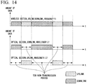
- Fig. 14 is a diagram showing an example of bandwidth utilization of a wireless section and an optical section in a mobile fronthaul when a wireless base station of a TDD scheme is accommodated.
- the wireless section data signals are bidirectionally transmitted by performing switching between the transmission of the downlink signal and the transmission of the uplink signal on the time axis.
- the optical section data signals are bidirectionally transmitted by alternately performing transmission of the uplink signal and transmission of the downlink signal on the time axis in accordance with the switching in the wireless section. Therefore, in an optical section adopting the WDM scheme, there may occur a period during which no signal is transmitted according to the TDD scheme (hereinafter referred to as a "TDD non-transmission period") on the time axis. That is, the TDD non-transmission period is a signal transmission stop period of the wireless communication system. The TDD non-transmission period occurs in both the uplink and the downlink.
- Non-Patent Document 3 There is a transmission system configured to superimpose a signal of a mobile system and a signal of another communication system which is Fiber To The Home (FFTH) or the like during the TDD non-transmission period (see Non-Patent Document 3).
- FFTH Fiber To The Home
- Fig. 15 is a diagram showing an example of a network system using a passive optical network (PON) in an optical section.
- An optical line terminal (OLT) (an optical subscriber line termination device) is an optical device configured to estimate the TDD non-transmission period on the basis of a signal transmitted from a wireless communication system via an optical fiber.
- Fig. 16 is a block diagram showing an example of a configuration of the OLT.
- the OLT allocates a bandwidth to the uplink signal of the wireless communication system in a fixed manner.
- allocating a bandwidth in a fixed manner is called “fixed bandwidth allocation (FBA).”
- FBA fixed bandwidth allocation
- the OLT stops the transmission of a signal of another communication system.
- a TDD frame information estimation unit estimates a configuration of a TDD subframe. That is, the TDD frame information estimation unit determines whether the TDD subframe is a TDD subframe allocated to an uplink or a downlink on the basis of an estimation result.
- the TDD frame information estimation unit estimates the TDD non-transmission period on the basis of a result of estimating the configuration of the TDD subframe and a result of estimating a timing of the TDD subframe. In order to estimate the TDD non-transmission period, the TDD frame information estimation unit needs to acquire a signal of a certain amount of traffic or more which is required (hereinafter referred to as a "required amount of traffic").
- the traffic monitoring unit adjusts a length of time for which the traffic of the uplink signal of the wireless communication system is monitored so that the TDD frame information estimation unit can acquire a signal having an amount of traffic greater than or equal to the required amount of traffic. Also, the traffic monitoring unit may monitor the uplink signal or the downlink signal.
- the TDD frame information estimation unit notifies a timing calculation unit of TDD frame pattern information. That is, the TDD frame information estimation unit transmits the result of estimating the configuration of the TDD subframe and information indicating the timing of the TDD subframe to the timing calculation unit.
- the timing calculation unit calculates a timing capable of being used by the wireless communication system for signal transmission (hereinafter referred to as a "usable timing") on the basis of the TDD frame pattern information.
- the timing calculation unit notifies a timing indication unit of the usable timing.
- the timing indication unit determines a timing to be used by the wireless communication system for signal transmission (hereinafter referred to as a "use timing") on the basis of the usable timing.
- the timing indication unit notifies a downlink layer 2 switch (L2SW) of the use timing.
- the timing indication unit transmits the use timing to a bandwidth allocation method selection unit so as to switch a method in which the bandwidth allocation method selection unit allocates the bandwidth to the uplink signal.
- the bandwidth allocation method selection unit allocates a bandwidth to an uplink signal of the wireless communication system according to FBA during a period in which a signal is transmitted according to the TDD scheme on the time axis (hereinafter referred to as a "TDD transmission period").
- the bandwidth allocation method selection unit allocates a bandwidth to a signal of another communication system according to FBA or dynamic bandwidth allocation (DBA) during the TDD non-transmission period.
- the bandwidth allocation method selection unit transmits information indicating a method of allocating a bandwidth (hereinafter referred to as "bandwidth allocation method information") to the bandwidth allocation unit.
- bandwidth allocation method information On the basis of the bandwidth allocation method information, the bandwidth allocation unit allocates an uplink signal of the wireless communication system to the bandwidth.
- the TDD frame information estimation unit may make this estimation error if the configuration of the TDD subframe of the wireless communication system is changed.
- the TDD frame information estimation unit estimates the TDD non-transmission period on the basis of the uplink signal of the wireless communication system. If an estimation error occurs, the TDD frame information estimation unit erroneously estimates the TDD non-transmission period.
- the estimation error affects communication quality of the wireless communication system. For example, if a communication system other than the wireless communication system transmits an uplink signal during the TDD transmission period, the uplink signal of the wireless communication system may be delayed.
- Fig. 17 is a time chart showing an example of traffic in a normal state.
- the normal state an estimated TDD non-transmission period and an actual TDD non-transmission period have the same timing if a propagation delay is ignored. That is, the uplink signal of the wireless communication system is transmitted in synchronization with a break of the configuration of the TDD subframe.
- the uplink signal of another communication system is transmitted in synchronization with a break of the configuration of the TDD subframe.
- Fig. 18 is a time chart showing an example of traffic of an abnormal state in which an estimation error occurs.
- the estimated TDD non-transmission period is different from the actual TDD non-transmission period.
- Transmission of the uplink signal of the wireless communication system is delayed until a signal transmission section allocated on the basis of the estimation result. This delay is on the order of milliseconds, but there is a problem in that the delay cannot be tolerated in a mobile fronthaul.
- an objective of the present invention is to provide a transmission system, a transmission method, and a transmission device capable of minimizing a delay occurring in a signal of a communication system even when an estimation error occurs in a configuration of the signal of the communication system in a transmission system, which accommodates a communication line of a communication system for performing communication according to TDD and a communication line of another communication system.
- a transmission system which accommodates a communication line of a first communication system for performing communication according to TDD and a communication line of a second communication system, the transmission system including: a relay unit configured to relay uplink signals and downlink signals in the first and second communication systems; a TDD information estimation unit configured to estimate a transmission stop period during which no uplink signal of the first communication system is transmitted; an estimation error detection unit configured to detect that the estimation of the transmission stop period is erroneous on the basis of the uplink signal or the downlink signal of the first communication system; and a bandwidth allocation unit configured to prioritize allocation of a bandwidth in the relay unit for the uplink signal of the first communication system over allocation of a bandwidth in the relay unit for the uplink signal of the second communication system if the estimation of the transmission stop period is erroneous.
- the bandwidth allocation unit allocates a detection bandwidth for relaying the uplink signal of the first communication system during the transmission stop period, and the estimation error detection unit determines that there is an error in the estimation of the transmission stop period if the uplink signal of the first communication system is received by the relay unit in the detection bandwidth.
- the estimation error detection unit determines that there is an error in the estimation of the transmission stop period if the downlink signal of the first communication system is received by the relay unit during a period other than the transmission stop period.
- the bandwidth allocation unit performs allocation to the uplink signal of the first communication system every predetermined cycle, and the bandwidth allocation unit updates a timing at which the cycle starts when the estimation error detection unit determines that there is an error in the estimation of the transmission stop period.
- the estimation error detection unit determines that there is an error in the estimation of the transmission stop period if an amount of traffic in an uplink of the first communication system periodically increases or decreases.
- a transmission method for use in a transmission system which accommodates a communication line of a first communication system for performing communication according to TDD and a communication line of a second communication system, the transmission method including the steps of: relaying uplink signals and downlink signals in the first and second communication systems; estimating a transmission stop period during which no uplink signal of the first communication system is transmitted; detecting that the estimation of the transmission stop period is erroneous on the basis of the uplink signal or the downlink signal of the first communication system; and prioritizing allocation of a bandwidth in the relaying for the uplink signal of the first communication system over allocation of a bandwidth in the relaying for the uplink signal of the second communication system if it is detected that the estimation of the transmission stop period is erroneous.
- a transmission device which accommodates a communication line of a first communication system for performing communication according to TDD and a communication line of a second communication system
- the transmission device including: a relay unit configured to relay uplink signals and downlink signals in the first and second communication systems; a TDD information estimation unit configured to estimate a transmission stop period during which no uplink signal of the first communication system is transmitted; an estimation error detection unit configured to detect that the estimation of the transmission stop period is erroneous on the basis of the uplink signal or the downlink signal of the first communication system; and a bandwidth allocation unit configured to prioritize allocation of a bandwidth in the relay unit for the uplink signal of the first communication system over allocation of a bandwidth in the relay unit for the uplink signal of the second communication system if the estimation of the transmission stop period is erroneous.
- the present invention it is possible to minimize a delay occurring in a signal of a communication system even when an estimation error occurs in a configuration of the signal of the communication system in a transmission system, which accommodates a communication line of a communication system for performing communication according to TDD and a communication line of another communication system.
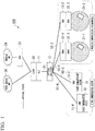
- Fig. 1 is a diagram showing an example of a configuration of a network system 100.
- the network system 100 (a transmission system) includes, an OLT 11 (a transmission device), an optical splitter 12, optical network units (ONUs) 13-1 to 13-4, mobile wireless terminals 21-1 and 21-2, RRHs 22-1 and 22-2 (wireless communication systems), a BBU 23, a mobile NW 24 (a mobile network), another communication system 31, another communication system 32, a layer 2 switch (L2SW) 33, another service NW 34 (another service network), an optical fiber 51, and optical fibers 52-1 to 52-4.
- OLT 11 a transmission device
- an optical splitter 12 optical network units
- ONUs optical network units
- ONUs optical network units
- mobile wireless terminals 21-1 and 21-2 mobile wireless terminals 21-1 and 21-2
- RRHs 22-1 and 22-2 wireless communication systems
- BBU 23 a mobile NW 24 (a mobile network)
- another communication system 31 another communication system 32
- L2SW layer 2 switch
- ONU 13 when items common to the ONUs 13-1 to 13-4 are described, a part of the reference sign will be omitted and the ONUs 13-1 to 13-4 are referred to as an "ONU 13."
- mobile wireless terminal 21 when items common to the mobile wireless terminals 21-1 and 21-2 are described, a part of the reference sign will be omitted and the mobile wireless terminals 21-1 and 21-2 are referred to as a "mobile wireless terminal 21.”
- RRHs 22-1 and 22-2 when items common to the RRHs 22-1 and 22-2 are described, a part of the reference sign will be omitted and the RRHs 22-1 and 22-2 are referred to as an "RRH 22.”
- optical fibers 52-1 to 52-4 when items common to the optical fibers 52-1 to 52-4 are described, a part of the reference sign will be omitted and the optical fibers 52-1 to 52-4 are referred to as an "optical fiber 52.”
- the network system 100 may include more ONUs 13.
- the network system 100 may include more mobile wireless terminals 21.
- the network system 100 may include more RRHs 22.
- the optical section is a section from the OLT 11 to the ONU 13.
- the optical section is, for example, a PON.
- a network topology of the network system 100 may have any configuration and is not limited to a specific topology. In the following, as an example, a case in which the network system 100 includes a PON will be described.
- the OLT 11 is an optical subscriber line termination device.
- the OLT 11 is a device higher than the ONU 13.
- the OLT 11 is managed by a communication carrier.
- the OLT 11 relays a signal of the RRH 22 to the BBU 23.
- the OLT 11 receives a signal of the RRH 22-1 via the ONU 13-1, the optical fiber 52-1, the optical splitter 12, and the optical fiber 51, and relays the received signal to the BBU 23.
- the OLT 11 receives a signal of the RRH 22-2 via the ONU 13-2, the optical fiber 52-2, the optical splitter 12, and the optical fiber 51, and relays the received signal to the BBU 23.
- the OLT 11 accommodates a communication line between the RRH 22 and the BBU 23.
- the OLT 11 relays signals to be transmitted and received between the RRH 22 and the BBU 23.
- the OLT 11 relays a signal of the other communication system 31 to the other service NW 34.
- the OLT 11 receives a signal of the other communication system 31 via the ONU 13-3, the optical fiber 52-3, the optical splitter 12, and the optical fiber 51, and relays the received signal to another communication system higher-order device of the other service NW 34.
- the OLT 11 receives a signal of the other communication system 32 via the ONU 13-4, the optical fiber 52-4, the optical splitter 12, and the optical fiber 51 and relays the received signal to another communication system higher-order device of the other service NW 34.
- the OLT 11 accommodates communication lines between the other communication systems 31 and 32 and the other communication system higher-order device of the other service NW.
- the OLT 11 relays signals to be transmitted and received between the other communication systems 31 and 32 and the other communication system higher-order device of the other service NW.
- the OLT 11 determines a TDD non-transmission period (a period during which communication based on the TDD scheme is absent) in the uplink and the downlink of the optical section.
- the OLT 11 transmits signals of the other communication systems 31 and 32 during the TDD non-transmission period of the RRH 22. That is, the OLT 11 relays the uplink signals acquired from the other communication systems 31 and 32 during the TDD non-transmission period of the uplink of the optical section.
- the OLT 11 relays downlink signals to the other communication systems 31 and 32 during the TDD non-transmission period of the downlink in the optical section.
- the OLT 11 transmits a signal to and from the ONU 13 according to an FDD scheme.
- FDD scheme different frequency bands are used for the uplink and the downlink.
- the OLT 11 transmits optical signals having different wavelengths in the uplink and the downlink according to a WDM scheme.
- the WDM scheme is a type of FDD scheme in optical transmission. In the WDM scheme, a first wavelength ⁇ 1 and a second wavelength ⁇ 2 of the optical signal are determined.
- the OLT 11 relays the downlink signal of the mobile NW 24 to the ONU 13-1 by using an optical signal of the first wavelength ⁇ 1 which is predetermined.
- the OLT 11 relays the downlink signal of the mobile NW 24 to the ONU 13-2 by using the optical signal of the first wavelength ⁇ 1.
- the OLT 11 relays a downlink signal of the other service NW 34 to the ONU 13-3 by using the optical signal of the first wavelength ⁇ 1.
- the OLT 11 relays a downlink signal of the other service NW 34 to the ONU 13-4 by using the optical signal of the first wavelength ⁇ 1.
- the OLT 11 relays an uplink signal of the ONU 13-1 to the mobile NW 24 by using the optical signal of the second wavelength ⁇ 2 which is predetermined.
- the OLT 11 relays an uplink signal of the ONU 13-2 to the mobile NW 24 by using the optical signal of the second wavelength ⁇ 2.
- the OLT 11 relays an uplink signal of the ONU 13-3 to the other service NW 34 by using the optical signal of the second wavelength ⁇ 2.
- the OLT 11 relays an uplink signal of the ONU 13-4 to the other service NW 34 by using the optical signal of the second wavelength ⁇ 2.
- the OLT 11 may relay a signal by using an optical signal and a radio signal other than the optical signal.
- the optical splitter 12 distributes an optical signal of a time division multiplex (TDM) scheme received via the optical fiber 51 to the ONUs 13-1 to 13-4.
- the optical splitter 12 multiplexes optical signals of a time division multiple access (TDMA) scheme received from the ONUs 13-1 to 13-4 via the optical fiber 52.
- the optical splitter 12 transmits a multiplexed optical signal to the OLT 11 via the optical fiber 51.
- TDM time division multiplex
- TDMA time division multiple access
- the ONU 13 is a communication device.
- the ONU 13 is an optical subscriber line network device.
- the ONU 13 is installed in a subscriber's home.
- the ONU 13-1 is connected to the RRH 22-1.
- the ONU 13-1 relays communication between the optical splitter 12 and the RRH 22-1.
- the ONU 13-2 is connected to the RRH 22-2.
- the ONU 13-2 relays communication between the optical splitter 12 and the RRH 22-2.
- the ONU 13-3 is connected to the other communication system 31.
- the ONU 13-3 relays communication between the optical splitter 12 and the other communication system 31.
- the ONU 13-4 is connected to the other communication system 32.
- the ONU 13-4 relays communication between the optical splitter 12 and the other communication system 32.
- the mobile wireless terminal 21 may communicate according to the TDD scheme by using a radio signal of a frequency f1 in the wireless section with the RRH 22.
- the RRH 22 executes uplink and downlink communication with the ONU 13 according to the TDD scheme.
- the same frequency band is used in the uplink and the downlink.
- signals are orthogonal on a time axis.
- the RRH 22 may perform communication according to the TDD scheme by using a radio signal of the frequency fl in the wireless section with the mobile wireless terminal 21.
- the wireless communication system may further include the ONU 13-2, the mobile wireless terminal 21-2, and the RRH 22-2.
- the BBU 23 is a signal processing unit of the wireless base station.
- the BBU 23 transmits a signal acquired from the L2SW 33 to the mobile NW 24.
- the BBU 23 transmits a signal acquired from the mobile NW 24 to the L2SW 33.
- the mobile NW 24 is a mobile communication network.
- the mobile NW 24 is a higher-order network for the wireless communication system.
- the mobile NW 24 includes communication devices.
- the mobile NW 24 communicates with the BBU 23.
- the other communication system 31 is more tolerant of requirements such as a high speed and low latency than a mobile network system including the mobile wireless terminal 21, the RRH 22, the BBU 23, and the mobile NW 24.
- the other communication system 32 is different from the other communication system 31.
- the other communication system 32 is more tolerant of requirements such as high speed and low delay than the mobile network system including the mobile wireless terminal 21, the RRH 22, the BBU 23, and the mobile NW 24.
- the reference signs will be omitted and the other communication system 31 and the other communication system 32 are referred to as the "other communication system.”
- the L2SW 33 transmits a signal acquired from the BBU 23 or the other service NW 34 to the OLT 11.
- the L2SW 33 transmits a signal acquired from the OLT 11 to the BBU 23 or the other service NW 34.
- the L2SW 33 determines a relay destination on the basis of a media access control (MAC) address.
- MAC media access control
- the other service NW 34 includes another communication system higher-order device which is a communication device.
- the other service NW 34 is a higher-order network for the other communication system.
- the other service NW 34 communicates with the other communication system via the L2SW 33.
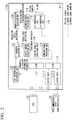
- Fig. 2 is a block diagram showing an example of a configuration of an OLT 110a in the first embodiment.
- the OLT 110a is the OLT 11 shown in Fig. 1 .
- the OLT 110a may be an external device connected to the OLT 11.
- the amount of traffic relayed by the OLT 11 is periodically excessive in the network system 100, there is a high likelihood that an estimation error will occur.
- an amount of data of the uplink signal waiting for transmission stored in buffer units of the ONUs 13-1 and 13-2 is larger than in the normal state.
- the buffer units of the ONUs 13-1 and 13-2 simultaneously transmit the uplink signals having a large amount of data at a transmittable time.
- an excessive amount of periodic traffic occurs. Congestion may occur when traffic exceeds a certain amount.
- the OLT 110a monitors an uplink signal of the wireless communication system transmitted from the ONU 13-1 or 13-2.
- the OLT 110a detects an increase or decrease in an amount of traffic of the network on the basis of an uplink signal of the wireless communication system.
- the OLT 110a includes a buffer unit 111-1, a buffer unit 111-2, an L2SW 112, a downlink signal processing unit 113, an electrical-to-optical (E/O) conversion unit 114, an optical-to-electrical (O/E) conversion unit 115, an uplink signal processing unit 116, an L2SW 117, a traffic amount extraction unit 118, an estimation error detection unit 119, a bandwidth allocation calculation unit 120, a bandwidth allocation unit 121, and a TDD information estimation unit 122.
- E/O electrical-to-optical
- O/E optical-to-electrical
- the buffer unit 111-1, the buffer unit 111-2, the L2SW 112, the downlink signal processing unit 113, the E/O conversion unit 114, the O/E conversion unit 115, the uplink signal processing unit 116, and the L2SW 117 are collectively referred to as a "relay unit.”
- the relay unit may be software functional units which function when a processor such as a central processing unit (CPU) executes a program stored in a memory.
- some or all of these functional units may be hardware functional units (circuits) such as a large scale integration circuit (LSI) and an application specific integrated circuit (ASIC).
- LSI large scale integration circuit
- ASIC application specific integrated circuit
- the buffer unit 111-1 acquires a downlink signal from the BBU 23.
- the buffer unit 111-1 temporarily stores the downlink signal.
- the buffer unit 111-1 transmits the downlink signal to the L2SW 112.
- the buffer unit 111-2 acquires a downlink signal from the other communication system higher-order device 36.
- the buffer unit 111-2 temporarily stores the downlink signal.
- the buffer unit 111-2 transmits the downlink signal to the L2SW 112.
- the L2SW 112 acquires a downlink signal from the buffer unit 111-1 or the buffer unit 111-2.
- the L2SW 112 transmits the downlink signal to the downlink signal processing unit 113.
- the downlink signal processing unit 113 acquires information indicating a bandwidth to be allocated to the uplink signal (hereinafter referred to as "bandwidth allocation information") from the bandwidth allocation unit 121.
- the downlink signal processing unit 113 converts the downlink signal acquired from the L2SW 112 into a frame for use in the PON. For example, the downlink signal processing unit 113 may generate a GATE frame including the bandwidth allocation information.
- the downlink signal processing unit 113 transmits the bandwidth allocation information to the E/O conversion unit 114.
- the E/O conversion unit 114 converts a downlink signal (an electrical signal) converted into a frame by the downlink signal processing unit 113 into an optical signal of a wavelength ⁇ 1.
- the E/O conversion unit 114 transmits the optical signal of the first wavelength ⁇ 1 to the optical fiber 51 via an optical coupler.
- the optical signal is transmitted to the ONU 13 via the optical fiber 51 and the optical fiber 52.
- the O/E conversion unit 115 acquires an optical signal of the second wavelength ⁇ 2 from the ONU 13 via the optical fiber 52, the optical splitter 12, and the optical fiber 51.
- the O/E conversion unit 115 converts the received optical signal into an electrical signal.
- the O/E conversion unit 115 transmits the electrical signal to the uplink signal processing unit 116.
- the uplink signal processing unit 116 converts the electrical signal acquired from the O/E conversion unit 115 into a predetermined signal according to the uplink signal.
- the uplink signal processing unit 116 transmits the converted uplink signal to the L2SW 117.
- the L2SW 117 acquires an uplink signal from the uplink signal processing unit 116.
- the L2SW 117 transmits the uplink signal to the BBU 23 or the other communication system higher-order device 36 in accordance with a destination of the uplink signal.
- the traffic amount extraction unit 118 monitors the uplink signal. For example, the traffic amount extraction unit 118 detects an excessive amount of traffic of the uplink signal of the wireless communication system.
- the traffic amount extraction unit 118 transmits information indicating that an excess state of traffic has been detected (hereinafter referred to as an "excess state notification") to the estimation error detection unit 119.
- An excessive amount of traffic is detected using a determination as to whether or not the traffic has exceeded a predetermined first threshold value or a determination as to whether a variance of traffic has exceeded a predetermined second threshold value. When the traffic has exceeded the first threshold, or when the variance of the traffic has exceeded the second threshold value, an excessive amount of traffic is detected.
- the estimation error detection unit 119 detects occurrence of an estimation error on the basis of an excess state notification. For example, if the excessive amount of traffic is periodic, the estimation error detection unit 119 determines that the estimation error has occurred. The estimation error detection unit 119 transmits information indicating that the estimation error has occurred (hereinafter referred to as "estimation error information") to the bandwidth allocation calculation unit 120.
- the bandwidth allocation calculation unit 120 re-calculates the bandwidth allocation information. That is, if the estimation error information is acquired, the bandwidth allocation calculation unit 120 re-determines the bandwidth allocation information.
- the bandwidth allocation calculation unit 120 transmits the bandwidth allocation information (a calculation result) to the bandwidth allocation unit 121.
- the bandwidth allocation unit 121 transmits the bandwidth allocation information to the ONU 13 via the downlink signal processing unit 113. If the estimation of the TDD non-transmission period is erroneous, the bandwidth allocation unit 121 initializes the allocation of a bandwidth to the uplink signal of the wireless communication system. For example, if the estimation of the TDD non-transmission period is erroneous, the bandwidth allocation unit 121 initializes a bandwidth allocation method. In the initial state, the bandwidth allocation unit 121 allocates a bandwidth to the uplink signal of the wireless communication system according to FBA. In the initial state, the bandwidth allocation unit 121 stops the transmission of a signal of the other communication system. An amount of traffic in the network system 100 returns to the initial state on the basis of the bandwidth allocation information.
- the TDD information estimation unit 122 includes a TDD frame information estimation unit, a timing calculation unit, a timing indication unit, and a bandwidth allocation method selection unit shown in Fig. 16 .
- the TDD frame information estimation unit of the TDD information estimation unit 122 estimates a configuration of a TDD subframe.
- the configuration of the TDD subframe indicates whether each TDD subframe in the TDD frame is allocated to any of a downlink subframe, an uplink subframe, and a special subframe.
- the TDD frame information estimation unit of the TDD information estimation unit 122 estimates the TDD non-transmission period on the basis of TDD frame pattern information indicating the estimated TDD subframe configuration.
- the timing calculation unit of the TDD information estimation unit 122 calculates a usable timing capable of being used for transmission of the uplink signal on the basis of the TDD frame pattern information.
- the timing calculation unit of the TDD information estimation unit 122 notifies the timing indication unit of the TDD information estimation unit 122 of the calculated usable timing.
- the timing calculation unit of the TDD information estimation unit 122 determines a use timing to be used for transmission of the uplink signal.
- the timing calculation unit of the TDD information estimation unit 122 transmits the determined use timing to the bandwidth allocation method selection unit of the TDD information estimation unit 122 in order to switch a method in which the bandwidth allocation method selection unit allocates a bandwidth to the uplink signal.
- the bandwidth allocation method selection unit of the TDD information estimation unit 122 allocates a bandwidth to the uplink signal of the wireless communication system according to FBA during a TDD transmission period based on a specification timing. In the normal state, the bandwidth allocation method selection unit of the TDD information estimation unit 122 allocates a bandwidth to the signal of the other communication system according to FBA or DBA during a TDD non-transmission period. The bandwidth allocation method selection unit of the TDD information estimation unit 122 transmits bandwidth allocation method information indicating a method of allocating a bandwidth to the bandwidth allocation unit 121. On the basis of the bandwidth allocation method information, the bandwidth allocation unit 121 allocates an uplink signal of the wireless communication system to the bandwidth.
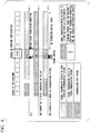
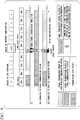
- Fig. 3 is a time chart showing an example of traffic in the first embodiment.
- the horizontal axis represents time.
- a first row from the top shows breaks of the configuration of the TDD subframe.
- a second row from the top shows a period during which the OLT 110a acquires a signal.
- a third row from the top shows a period during which the ONU 13-3 or 13-4 transmits a signal and a period during which the ONU 13-3 or 13-4 stops the transmission of the signal.
- a fourth row from the top shows a period during which the ONU 13-1 or 13-2 transmits a signal and a period during which the ONU 13-1 or 13-2 stops the transmission of the signal.
- a timing at which the configuration of the TDD subframe is changed is a transmission stop period
- the ONU 13-1 or 13-2 waits for signal transmission. Because the timing at which the configuration of the TDD subframe is changed is the transmission stop period, the ONU 13-1 or 13-2 causes a signal to be stored in the buffer unit.
- a period during which the uplink signal can be transmitted is referred to as a "signal transmission period.”
- the ONU 13-1 or 13-2 transmits an uplink signal on standby for transmission and an uplink signal to be currently transmitted during the signal transmission period of the wireless communication system. Thus, an excessive amount of traffic occurs.
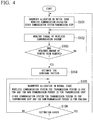
- Fig. 4 is a flowchart showing an example of the operation of the OLT 110a in the first embodiment.
- the bandwidth allocation unit 121 transmits the bandwidth allocation information to the ONU 13 via the downlink signal processing unit 113.
- the bandwidth allocation unit 121 allocates a bandwidth to the uplink signal of the wireless communication system according to FBA.
- the bandwidth allocation unit 121 stops the transmission of a signal of another communication system (step S101).
- the traffic amount extraction unit 118 monitors the uplink signal of the wireless communication system (step S102).
- the TDD information estimation unit 122 determines whether or not a signal of a required amount of traffic or more has been acquired (step S103). If the TDD information estimation unit 122 has not acquired a signal of a required amount of traffic or more (step S103: NO), the traffic amount extraction unit 118 returns the process to step S102. If the TDD information estimation unit 122 has acquired a signal of a required amount of traffic or more (step S103: YES), the TDD information estimation unit 122 estimates a configuration of a TDD sub frame (step S104).
- the TDD information estimation unit 122 allocates a bandwidth to the uplink signal of the wireless communication system according to FBA during the TDD transmission period. In the normal state, the TDD information estimation unit 122 stops the transmission of the uplink signal of the wireless communication system during the TDD non-transmission period.
- the TDD information estimation unit 122 stops the transmission of the signal of the other communication system during the TDD transmission period. In the normal state, the TDD information estimation unit 122 allocates the bandwidth to the signal of the other communication system according to FBA or DBA during the TDD non-transmission period (step S105).
- the estimation error detection unit 119 determines whether or not an estimation error has occurred (step S106). If an estimation error has occurred (step S106: YES), the bandwidth allocation unit 121 initializes the allocation of a bandwidth to the uplink signal of the wireless communication system. That is, the bandwidth allocation unit 121 returns the process to step S101. If no estimation error has occurred (step S106: NO), the bandwidth allocation unit 121 returns the process to step S105.
- the network system 100 of the first embodiment is a transmission system configured to accommodate a communication line of a communication system performing communication according to TDD and a communication line of another communication system which is different therefrom.
- the network system 100 includes a relay unit, a TDD information estimation unit 122, an estimation error detection unit 119, a bandwidth allocation unit 121, and an ONU 13.
- the relay unit relays an uplink signal and a downlink signal of the wireless communication system including the RRH 22.
- the TDD information estimation unit 122 estimates a timing of a transmission stop section.
- the estimation error detection unit 119 detects that the estimation of the timing of the transmission stop period is erroneous on the basis of the uplink signal or the downlink signal.
- the bandwidth allocation unit 121 initializes the allocation of the bandwidth to the uplink signal of the wireless communication system.
- the ONU 13 transmits the uplink signal of the wireless communication system on the basis of the bandwidth allocation.
- the estimation error detection unit 119 of the first embodiment determines that the estimation of the timing of the transmission stop period is erroneous. If it is determined that there is an error in the estimation, the bandwidth allocation unit 121 initializes the allocation of the bandwidth, thereby prioritizing the allocation of bandwidth to the uplink signal of the wireless communication system.
- the network system 100 of the first embodiment (a transmission system) configured to accommodate a communication system for performing communication according to TDD and another communication system can minimize a delay occurring in a signal of the wireless communication system even when an estimation error occurs in a configuration of the signal of the communication system.
- the network system 100 of the first embodiment accommodates a wireless communication system of a TDD scheme by using a PON.
- the network system 100 of the first embodiment detects an estimation error with respect to a configuration of a TDD subframe.
- the OLT 110a of the first embodiment (a transmission device) initializes bandwidth allocation information for the signal of the ONU 13.
- the OLT 110a of the first embodiment may initialize bandwidth allocation information for signals of all the ONUs 13 accommodated in the OLT 110a.
- the network system 100 of the first embodiment reduces the delay of the uplink signal of the wireless communication system. For example, the network system 100 of the first embodiment reduces the delay of the uplink signal of the wireless communication system caused by erroneous estimation of the configuration of the TDD subframe.
- the network system 100 of the first embodiment can satisfy an allowable amount of delay required for a mobile fronthaul.
- the network system 100 of the first embodiment can enhance the effectiveness of the network system 100.
- the OLT 110a of the first embodiment can share a wavelength of the optical signal with respect to the RRH 22 and the other communication system 31.
- the OLT 110a of the first embodiment can reduce the number of core wires of the optical fiber 51 by using an optical signal having a common wavelength.
- the OLT 110a of the first embodiment can reduce the number of devices in the network system 100 by using an optical signal having a common wavelength.
- a second embodiment is different from the first embodiment in that an OLT 110b includes a detection bandwidth determination unit 123. In the second embodiment, only differences from the first embodiment will be described.
- Fig. 5 is a diagram showing an example of a configuration of the OLT 110b in the second embodiment.
- the OLT 110b is the OLT 11 shown in Fig. 1 .
- the OLT 110b may be an external device connected to the OLT 11.
- the OLT 110b includes a buffer unit 111-1, a buffer unit 111-2, an L2SW 112, a downlink signal processing unit 113, an E/O conversion unit 114, an O/E conversion unit 115, an uplink signal processing unit 116, an L2SW 117, an estimation error detection unit 119, a bandwidth allocation calculation unit 120, a bandwidth allocation unit 121, a TDD information estimation unit 122, and a detection bandwidth determination unit 123.
- the bandwidth allocation unit 121 provides a bandwidth for detecting an estimation error (hereinafter referred to as an "estimation error detection bandwidth") during the TDD non-transmission period.
- an estimation error detection bandwidth a period during which the estimation error detection bandwidth is provided.
- the detection period is a period during which the uplink signal processing unit 116 does not acquire the uplink signal of the wireless communication system in the normal state. In the abnormal state, the detection period is a period during which the uplink signal processing unit 116 may acquire the uplink signal of the wireless communication system.
- the uplink signal processing unit 116 transmits information indicating an amount of data of the uplink signal in the estimation error detection bandwidth to the detection bandwidth determination unit 123.
- the detection bandwidth determination unit 123 determines whether or not the uplink signal of the wireless communication system has been acquired during the detection period on the basis of the information indicating the amount of data of the uplink signal in the estimation error detection bandwidth.
- the detection bandwidth determination unit 123 transmits a determination result to the estimation error detection unit 119.
- the estimation error detection unit 119 detects that an estimation error has occurred on the basis of the determination result of the detection bandwidth determination unit 123. That is, if the uplink signal of the wireless communication system is acquired during the detection period, the estimation error detection unit 119 determines that an estimation error has occurred. If it is detected that an estimation error has occurred, the estimation error detection unit 119 transmits estimation error information to the bandwidth allocation calculation unit 120.
- the bandwidth allocation calculation unit 120 re-calculates the bandwidth allocation information. That is, if the estimation error information is acquired, the bandwidth allocation calculation unit 120 re-determines the bandwidth allocation information.
- the bandwidth allocation calculation unit 120 transmits the bandwidth allocation information to the bandwidth allocation unit 121.
- the bandwidth allocation unit 121 transmits the bandwidth allocation information to an ONU 13 via the downlink signal processing unit 113.
- the bandwidth allocation unit 121 allocates a bandwidth to the uplink signal of the wireless communication system according to FBA (setting in the initial state).
- the bandwidth allocation unit 121 stops the transmission of a signal of the other communication system (setting in the initial state).
- the amount of traffic in the network system 100 returns to the initial state on the basis of the bandwidth allocation information.
- the downlink signal processing unit 113 transmits bandwidth allocation information (a downlink control signal) as a GATE signal (a transmission permission signal) (a GATE frame) to the ONU 13.
- the downlink signal processing unit 113 may transmit the bandwidth allocation information to all the ONUs 13 connected to the OLT 110b.
- the TDD frame information estimation unit of the TDD information estimation unit 122 estimates the configuration of the TDD subframe.
- the TDD frame information estimation unit of the TDD information estimation unit 122 estimates the TDD non-transmission period.
- the bandwidth allocation method selection unit of the TDD information estimation unit 122 allocates a bandwidth to the uplink signal of the wireless communication system according to FBA during the TDD transmission period.
- the bandwidth allocation method selection unit of the TDD information estimation unit 122 allocates a bandwidth to the signal of the other communication system according to FBA or DBA during the TDD non-transmission period.
- the bandwidth allocation method selection unit of the TDD information estimation unit 122 transmits bandwidth allocation method information indicating a method of allocating a bandwidth to the bandwidth allocation unit 121.
- the bandwidth allocation unit 121 allocates an uplink signal of the wireless communication system to the bandwidth.
- Fig. 6 is a time chart showing an example of traffic in the second embodiment.
- the horizontal axis represents time.
- a first row from the top shows breaks of the configuration of the TDD subframe.
- a second row from the top shows a period during which the OLT 110a acquires a signal.
- a third row from the top shows a period during which an ONU 13-3 or 13-4 transmits a signal and a period during which the ONU 13-3 or 13-4 stops the transmission of the signal.
- a fourth row from the top shows a period during which an ONU 13-1 or 13-2 transmits a signal and a period during which the ONU 13-1 or 13-2 stops the transmission of the signal.
- allocation to some TDD subframes is changed from downlink subframes to uplink subframes.
- a detection period is allocated during the transmission stop period including a timing at which the configuration of the TDD subframe is changed.
- the OLT 110b acquires an uplink signal of the wireless communication system during the detection period.
- the downlink signal processing unit 113 of the downlink signal processing unit 113 transmits bandwidth allocation information as a GATE signal to the ONU 13.
- the ONU 13-1 or 13-2 transmits a signal on standby for transmission and a signal to be currently transmitted during the signal transmission period of the wireless communication system.
- the bandwidth allocation unit 121 of the second embodiment determines the detection period.
- the estimation error detection unit 119 determines that the estimation of the transmission stop period is erroneous.
- the OLT 110b returns the bandwidth allocation to the initial state, and then allocates a bandwidth on the basis of a newly estimated transmission stop period.
- the network system 100 (a transmission system) of the second embodiment configured to accommodate a communication line of a communication system for performing communication according to TDD and a communication line of another communication system can minimize a delay occurring in a signal of a communication system even when an estimation error occurs in a configuration of the signal of the communication system.
- a third embodiment is different from the second embodiment in that the estimation error detection unit 119 constantly monitors a downlink signal of a wireless communication system. In the third embodiment, only differences from the second embodiment will be described.
- Fig. 7 is a diagram showing an example of a configuration of an OLT 110c in the third embodiment.
- the OLT 110c includes a buffer unit 111-1, a buffer unit 111-2, an L2SW 112, a downlink signal processing unit 113, an E/O conversion unit 114, an O/E conversion unit 115, an uplink signal processing unit 116, an L2SW 117, an estimation error detection unit 119, a bandwidth allocation calculation unit 120, a bandwidth allocation unit 121, and a TDD information estimation unit 122.
- the downlink signal processing unit 113 constantly monitors an amount of data of the downlink signal of the wireless communication system.
- the downlink signal processing unit 113 transmits information indicating the amount of data of the downlink signal of the wireless communication system to the estimation error detection unit 119.
- the estimation error detection unit 119 constantly monitors whether or not an estimation error has occurred on the basis of information indicating the amount of data of the downlink signal of the wireless communication system.
- the estimation error detection unit 119 detects an estimation error on the basis of whether or not the downlink signal of the wireless communication system has been transmitted during a signal transmission period of the wireless communication system.
- the estimation error detection unit 119 constantly monitors whether or not an estimation error has occurred. If the downlink signal of the wireless communication system is transmitted during the signal transmission period of the wireless communication system, the estimation error detection unit 119 determines that an estimation error has occurred. If the estimation error detection unit 119 detects that an estimation error has occurred, the estimation error detection unit 119 transmits estimation error information to the bandwidth allocation calculation unit 120.
- Fig. 8 is a time chart showing an example of traffic in the third embodiment.
- the horizontal axis represents time.
- a first row from the top shows breaks of the configuration of the TDD subframe.
- a second row from the top shows a period during which the OLT 110a acquires a signal.
- a third row from the top shows a period during which an ONU 13-3 or 13-4 transmits a signal and a period during which the ONU 13-3 or 13-4 stops the transmission of the signal.
- a fourth row from the top shows a period during which an ONU 13-1 or 13-2 transmits a signal and a period during which the ONU 13-1 or 13-2 stops the transmission of the signal.
- the OLT 110c transmits a downlink signal of the wireless communication system during the signal transmission period.
- the downlink signal processing unit 113 transmits bandwidth allocation information as a GATE signal to the ONU 13-1.
- the estimation error detection unit 119 of the third embodiment determines that the estimation of a timing of the transmission stop period is erroneous.
- the OLT 110c returns the bandwidth allocation to the initial state, and then allocates a bandwidth on the basis of a newly estimated transmission stop period.
- the network system 100 (a transmission system) of the third embodiment configured to accommodate a communication line of a communication system for performing communication according to TDD and a communication line of another communication system can minimize a delay occurring in a signal of a communication system even when an estimation error occurs in a configuration of the signal of the communication system.
- a fourth embodiment is different from the first to third embodiments in that a cycle of dynamic bandwidth allocation (hereinafter referred to as a "DBA cycle") is initialized.
- An OLT 11 may be any one of the OLT 110a described in the first embodiment, the OLT 110b shown in the second embodiment, and the OLT 110c shown in the third embodiment. In the fourth embodiment, as an example, only differences from the second embodiment will be described.
- the OLT 110b allocates a bandwidth to a signal of an ONU 13 in the DBA cycle. If the OLT 110b returns a setting of signal bandwidth allocation to the ONU 13 to an initial state, the ONU 13 validates the bandwidth allocation setting at a timing at which the next DBA period starts. Thus, if the timing at which the DBA cycle starts is not initialized (reset), a time at which the ONU 13 transmits an uplink signal is delayed. That is, if the timing of the DBA period is not initialized, a transmission delay due to a delay of the DBA cycle occurs. The OLT 110b initializes a timing of the DBA cycle so that no transmission delay is caused by the delay of the DBA cycle. That is, the OLT 110b updates a timing at which the bandwidth is allocated so that no transmission delay is caused by the delay of the DBA cycle.
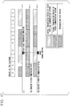
- Fig. 9 is a time chart showing an example of traffic in the fourth embodiment.
- the horizontal axis represents time.
- a first row from the top shows breaks of the configuration of the TDD subframe.
- a second row from the top shows breaks of a DBA cycle.
- a third row from the top shows a period during which a signal is acquired by the OLT 110b.
- a fourth row from the top shows a period during which an ONU 13-3 or 13-4 transmits a signal and a period during which the ONU 13-3 or 13-4 stops the transmission of the signal.
- a fifth row from the top shows a period during which an ONU 13-1 or 13-2 transmits a signal and a period during which the ONU 13-1 or 13-2 stops the transmission of a signal.
- allocation to some TDD subframes is changed from downlink subframes to uplink subframes.
- a detection period is allocated during a period in which a configuration of a TDD subframe is changed.
- the OLT 110b acquires an uplink signal of the wireless communication system during the detection period.
- the downlink signal processing unit 113 of the OLT 110b initializes a timing of a DBA cycle.
- the downlink signal processing unit 113 of the OLT 110b transmits information indicating a timing of a signal transmission period and bandwidth allocation information as a GATE signal to the ONU 13.
- the ONU 13-1 or 13-2 transmits an uplink signal during the signal transmission period of the wireless communication system.
- a TDD frame information estimation unit of a TDD information estimation unit 122 may estimate the configuration of the TDD subframe after the downlink signal processing unit 113 initializes a timing of the DBA cycle.
- the downlink signal processing unit 113 may initialize the timing of the DBA cycle according to a timing at which a configuration of the TDD subframe (a TDD subframe pattern) is switched. Thereby, the downlink signal processing unit 113 can cause a switching time of the configuration of the TDD subframe to match a timing (a start time or an end time) of the DBA cycle.
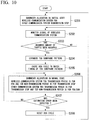
- Fig. 10 is a flowchart showing an example of an operation of the OLT in the fourth embodiment.
- the bandwidth allocation unit 121 transmits the bandwidth allocation information to the ONU 13 via the downlink signal processing unit 113.
- the bandwidth allocation unit 121 allocates a bandwidth to an uplink signal of the wireless communication system according to FBA.
- the bandwidth allocation unit 121 stops the transmission of the signal of the other communication system (step S201).
- the traffic amount extraction unit 118 monitors the uplink signal of the wireless communication system (step S202).
- the TDD information estimation unit 122 determines whether or not a signal having a required amount of traffic or more has been acquired (step S203). If the TDD information estimation unit 122 has not acquired a signal having a required amount of traffic or more (step S203: NO), the traffic amount extraction unit 118 returns the process to step S202. If the TDD information estimation unit 122 has acquired a signal having a required amount of traffic or more (step S203: YES), the TDD information estimation unit 122 estimates a configuration of a TDD subframe (step S204).
- the downlink signal processing unit 113 causes a timing of the DBA cycle to match a timing at which the configuration of the TDD subframe (a TDD subframe pattern) is switched (step S205).
- the TDD information estimation unit 122 allocates a bandwidth to the uplink signal of the wireless communication system according to FBA during the TDD transmission period. In the normal state, the TDD information estimation unit 122 stops the transmission of the uplink signal of the wireless communication system during a TDD non-transmission period.
- the TDD information estimation unit 122 stops the transmission of the signal of the other communication system during the TDD transmission period. In the normal state, the TDD information estimation unit 122 allocates the bandwidth to the signal of the other communication system according to FBA or DBA during the TDD non-transmission period (step S206).
- step S207 It is determined whether or not an estimation error has occurred (step S207). If an estimation error has occurred (step S207: YES), the downlink signal processing unit 113 initializes a timing of the DBA cycle according to a timing at which a configuration of the TDD subframe (a TDD subframe pattern) is switched (step S208). The bandwidth allocation unit 121 returns the process to step S201. If an estimation error has not occurred (step S207: NO), the bandwidth allocation unit 121 returns the process to step S206.
- the bandwidth allocation unit 121 of the fourth embodiment updates a timing at which a bandwidth is allocated to the uplink signal (a timing at which the DBA cycle starts).
- the network system 100 (a transmission system) of the fourth embodiment configured to accommodate a communication line of a communication system for performing communication according to TDD and a communication line of another communication system can minimize a propagation delay occurring in a signal of a communication system to a propagation delay due to optical fibers 51 and 52 even when an estimation error occurs in a configuration of the signal of the communication system.
- a fifth embodiment is different from the first to fourth embodiments in that bandwidth allocation information in an initial state is stored in a memory.
- bandwidth allocation information in an initial state is stored in a memory.
- Fig. 11 is a diagram showing an example of a configuration of an OLT 110d in the fifth embodiment.
- the OLT 110d is the OLT 11 shown in Fig. 1 .
- the OLT 110d may be an external device connected to the OLT 11.
- the OLT 110d includes a buffer unit 111-1, a buffer unit 111-2, an L2SW 112, a downlink signal processing unit 113, an E/O conversion unit 114, an O/E conversion unit 115, an uplink signal processing unit 116, an L2SW 117, an estimation error detection unit 119, a bandwidth allocation calculation unit 120, a bandwidth allocation unit 121, a TDD information estimation unit 122, a detection bandwidth determination unit 123, and a memory 124.
- the memory 124 is configured using a storage device having a non-volatile memory (a non-transitory recording medium) such as a magnetic hard disk device or a semiconductor storage device.
- the estimation error detection unit 119 causes the memory 124 to store estimation error information.
- the bandwidth allocation calculation unit 120 causes the memory 124 to store the bandwidth allocation information in the initial state. If the estimated error information is acquired from the memory 124, the bandwidth allocation unit 121 acquires the bandwidth allocation information in the initial state from the memory 124. That is, if the estimation error detection unit 119 detects an estimation error, the bandwidth allocation unit 121 acquires the bandwidth allocation information in the initial state from the memory 124. If the estimation error detection unit 119 detects the estimation error, the bandwidth allocation unit 121 transmits the bandwidth allocation information in the initial state acquired from the memory 124 to an ONU 13 via the downlink signal processing unit 113.
- the bandwidth allocation unit 121 transmits the bandwidth allocation information in the initial state acquired from the memory 124 to the ONU 13 via the downlink signal processing unit 113 if the estimation error detection unit 119 detects the estimation error.
- a network system 100 (a transmission system) of the fifth embodiment does not need to re-calculate bandwidth allocation so as to cause the bandwidth allocation to transition to the initial state.
- the network system 100 of the fifth embodiment can reduce a transmission delay due to processing such as transmission order control.
- a sixth embodiment is different from the first to fifth embodiments in that the OLT 11 includes a functional unit that does not transition to an initial state even when an estimation error detection unit 119 detects an estimation error.
- the OLT 11 includes a functional unit that does not transition to an initial state even when an estimation error detection unit 119 detects an estimation error.
- the bandwidth allocation unit 121 allocates a bandwidth to an uplink signal of a wireless communication system according to FBA in a TDD subframe from which an error is detected. If the estimation error detection unit 119 detects an estimation error, the bandwidth allocation unit 121 stops the transmission of a signal of another communication system in the TDD subframe from which the error is detected.
- the bandwidth allocation unit 121 allocates a bandwidth to the uplink signal of the wireless communication system according to FBA for each TDD subframe during a TDD transmission period. If the estimation error detection unit 119 does not detect an estimation error, the bandwidth allocation unit 121 allocates a bandwidth to a signal of another communication system for each TDD subframe during a TDD non-transmission period according to FBA or DBA.
- the bandwidth allocation unit 121 does not cause other predetermined functional units to transition to the initial state. If the estimation error detection unit 119 detects an estimation error, the bandwidth allocation unit 121 allocates a bandwidth to an uplink signal of the wireless communication system according to FBA in the TDD subframe from which the estimation error is detected. When the estimation error detection unit 119 detects an estimation error, the bandwidth allocation unit 121 stops the transmission of the signal of the other communication system in the TDD subframe from which the estimation error is detected.
- the network system 100 (a transmission system) of the sixth embodiment does not transition to the initial state even when an estimation error occurs, it is possible to minimize the number of times that the communication of the other communication system is disabled.
- the network system 100 of the sixth embodiment can reduce an influence on other communication systems.
- the first to sixth embodiments may be combined.
- the network system 100 (the transmission system) can increase the accuracy of detection of an estimation error.
- an L2SW 33 and an OLT 11 may be configured as one device.
- a condition that the estimation error is consecutively detected a predetermined number of times may be used instead of detecting an estimation error as the condition for the bandwidth allocation unit 121 to initialize the allocation of the bandwidth. It is possible to improve the accuracy of detection of the estimation error by determining that the estimation error is occurring on the basis of the fact that the estimation error has been detected a plurality of times consecutively. By improving the detection accuracy, the likelihood that the initialization of bandwidth allocation is erroneously performed is reduced, and relaying of a plurality of communication systems is stably performed.
- At least some of the functions of the transmission system and the transmission device in the above-described embodiment may be implemented by a computer.
- the functions may be implemented by recording a program for implementing the functions on a computer-readable recording medium and causing a computer system to read and execute the program recorded on the recording medium.
- the "computer system” described here is assumed to include an operating system (OS) and hardware such as peripheral devices.
- the "computer-readable recording medium” refers to a storage device including a flexible disk, a magneto-optical disc, a read only memory (ROM), a portable medium such as a compact disc (CD)-ROM, and a hard disk embedded in the computer system.
- the "computer-readable recording medium” is assumed to include a computer-readable recording medium for dynamically holding a program for a short time as in a communication line when the program is transmitted via a network such as the Internet or a communication circuit such as a telephone circuit and a computer-readable recording medium for holding the program for a predetermined time as in a volatile memory inside the computer system including a server and a client when the program is transmitted.
- the above-described program may be used to implement some of the above-described functions.
- the program may implement the above-described functions in combination with a program already recorded on the computer system or may be implemented using a programmable logic device such as a field programmable gate array (FPGA).
- FPGA field programmable gate array
- the present invention can also be applied to a field of application for minimizing a delay caused when an error occurs in estimation for switching of transmission and reception in a first communication system in a system configured to accommodate a communication line of the first communication system for performing communication according to TDD and a communication line of a second communication system.
Landscapes
- Engineering & Computer Science (AREA)
- Signal Processing (AREA)
- Computer Networks & Wireless Communication (AREA)
- Computing Systems (AREA)
- Physics & Mathematics (AREA)
- Electromagnetism (AREA)
- Small-Scale Networks (AREA)
- Bidirectional Digital Transmission (AREA)
- Time-Division Multiplex Systems (AREA)
- Mobile Radio Communication Systems (AREA)
Abstract
Description
- The present invention relates to a transmission system, a transmission method, and a transmission device.
- Priority is claimed on Japanese Patent Application No.
2015-200372, filed October 8, 2015 - In wireless communication systems, an antenna unit (RRH: Remote Radio Head) and a signal processing unit (BBU: Baseband Unit) of a wireless base station may be separate. The RRH and the BBU communicate via a mobile fronthaul.
-
Fig. 12 is a diagram showing an example of a configuration of a mobile fronthaul. In the mobile fronthaul, communication of a wavelength division multiplex (WDM) scheme is used. In the WDM scheme, a wavelength of light used in an uplink is different from a wavelength of light used in a downlink. The uplink is a link from a lower-order device that is a mobile wireless terminal or the like to a higher-order device that is a BBU or the like. The downlink is a link from the higher-order device to the lower-order device. By using the WDM scheme, the transmission system simultaneously transmits an uplink signal and a downlink signal via a single optical fiber (see Non-Patent Document 1). - The transmission system may relay a signal of a communication system based on a time division duplex (TDD) scheme according to a frequency division duplex (FDD) scheme. In the FDD scheme, different frequency bands are used for the uplink and the downlink. In the TDD scheme, the same frequency band is used for the uplink and the downlink. In the TDD scheme, the uplink signal and the downlink signal are switched on a time axis.
-
Fig. 13 is a diagram showing a configuration of a TDD frame of Long Term Evolution (LTE). In LTE, the TDD frame includes 10 TDD subframes. There are seven types of combination of allocation of a downlink subframe, an uplink subframe, and a special subframe with respect to the TDD subframes. In LTE, the time length of the TDD subframe is 1 millisecond. In the TDD scheme, allocation to each TDD subframe in the TDD frame is determined in accordance with uplink and downlink traffic. A ratio between uplink and downlink communication times in the TDD frame can be flexibly changed because allocation to the TDD subframe is determined in accordance with the traffic. - The special subframe (S) includes a downlink pilot time slot (DwPTS), a guard period (GP), and an uplink pilot time slot (UpPTS) (see Non-Patent Document 2). DwPTS is a time slot used for transmission of a downlink control signal. UpPTS is a time slot used for transmission of an uplink control signal. GP is a protection time for switching between an uplink signal and a downlink signal.
-
Fig. 14 is a diagram showing an example of bandwidth utilization of a wireless section and an optical section in a mobile fronthaul when a wireless base station of a TDD scheme is accommodated. In the wireless section, data signals are bidirectionally transmitted by performing switching between the transmission of the downlink signal and the transmission of the uplink signal on the time axis. Also, in the optical section, data signals are bidirectionally transmitted by alternately performing transmission of the uplink signal and transmission of the downlink signal on the time axis in accordance with the switching in the wireless section. Therefore, in an optical section adopting the WDM scheme, there may occur a period during which no signal is transmitted according to the TDD scheme (hereinafter referred to as a "TDD non-transmission period") on the time axis. That is, the TDD non-transmission period is a signal transmission stop period of the wireless communication system. The TDD non-transmission period occurs in both the uplink and the downlink. - There is a transmission system configured to superimpose a signal of a mobile system and a signal of another communication system which is Fiber To The Home (FFTH) or the like during the TDD non-transmission period (see Non-Patent Document 3).
-
Fig. 15 is a diagram showing an example of a network system using a passive optical network (PON) in an optical section. An optical line terminal (OLT) (an optical subscriber line termination device) is an optical device configured to estimate the TDD non-transmission period on the basis of a signal transmitted from a wireless communication system via an optical fiber. -
Fig. 16 is a block diagram showing an example of a configuration of the OLT. In an initial state, the OLT allocates a bandwidth to the uplink signal of the wireless communication system in a fixed manner. Hereinafter, allocating a bandwidth in a fixed manner is called "fixed bandwidth allocation (FBA)." In the initial state, the OLT stops the transmission of a signal of another communication system. A TDD frame information estimation unit estimates a configuration of a TDD subframe. That is, the TDD frame information estimation unit determines whether the TDD subframe is a TDD subframe allocated to an uplink or a downlink on the basis of an estimation result. - The TDD frame information estimation unit estimates the TDD non-transmission period on the basis of a result of estimating the configuration of the TDD subframe and a result of estimating a timing of the TDD subframe. In order to estimate the TDD non-transmission period, the TDD frame information estimation unit needs to acquire a signal of a certain amount of traffic or more which is required (hereinafter referred to as a "required amount of traffic").
- The traffic monitoring unit adjusts a length of time for which the traffic of the uplink signal of the wireless communication system is monitored so that the TDD frame information estimation unit can acquire a signal having an amount of traffic greater than or equal to the required amount of traffic. Also, the traffic monitoring unit may monitor the uplink signal or the downlink signal.
- The TDD frame information estimation unit notifies a timing calculation unit of TDD frame pattern information. That is, the TDD frame information estimation unit transmits the result of estimating the configuration of the TDD subframe and information indicating the timing of the TDD subframe to the timing calculation unit. The timing calculation unit calculates a timing capable of being used by the wireless communication system for signal transmission (hereinafter referred to as a "usable timing") on the basis of the TDD frame pattern information. The timing calculation unit notifies a timing indication unit of the usable timing.
- The timing indication unit determines a timing to be used by the wireless communication system for signal transmission (hereinafter referred to as a "use timing") on the basis of the usable timing. The timing indication unit notifies a
downlink layer 2 switch (L2SW) of the use timing. The timing indication unit transmits the use timing to a bandwidth allocation method selection unit so as to switch a method in which the bandwidth allocation method selection unit allocates the bandwidth to the uplink signal. - In a state in which the TDD non-transmission period is estimated correctly (hereinafter referred to as a "normal state"), the bandwidth allocation method selection unit allocates a bandwidth to an uplink signal of the wireless communication system according to FBA during a period in which a signal is transmitted according to the TDD scheme on the time axis (hereinafter referred to as a "TDD transmission period"). In the normal state, the bandwidth allocation method selection unit allocates a bandwidth to a signal of another communication system according to FBA or dynamic bandwidth allocation (DBA) during the TDD non-transmission period. The bandwidth allocation method selection unit transmits information indicating a method of allocating a bandwidth (hereinafter referred to as "bandwidth allocation method information") to the bandwidth allocation unit. On the basis of the bandwidth allocation method information, the bandwidth allocation unit allocates an uplink signal of the wireless communication system to the bandwidth.
-
- [Non-Patent Document 1] "NTT Technical Journal, Basic Technology Basic Course [GE-PON Technology], Part 1: PON," [online], 2005, Nippon Telegraph and Telephone Corporation, [found on May 21, 2015], Internet <URL http://www.ntt.co.jp/journal/0508/files/jn200508071.pdf>
- [Non-Patent Document 2] 3GPP, "Evolved Universal Terrestrial Radio Access (E-UTRA) and Evolved Universal Terrestrial Radio Access Network (E-UTRAN); Overall description; Stage 2 (Release 12)," 3GPP TR 36.300 (V12.4.0), 2013 (5 Physical Layer for E-UTRA)
- [Non-Patent Document 3] Hisano et al., "A Study of Accommodation of Mobile and Other Systems in A PON system Using mobile TDD Frame Estimation," Society Conference of Electronic Information Communication 2015, B-8-10, September 2015
- Hereinafter, the fact that the uplink TDD subframe is estimated to be the downlink TDD subframe or the fact that the downlink TDD subframe is estimated to be the uplink TDD subframe is referred to as an "estimation error." For example, the TDD frame information estimation unit may make this estimation error if the configuration of the TDD subframe of the wireless communication system is changed.
- The TDD frame information estimation unit estimates the TDD non-transmission period on the basis of the uplink signal of the wireless communication system. If an estimation error occurs, the TDD frame information estimation unit erroneously estimates the TDD non-transmission period. The estimation error affects communication quality of the wireless communication system. For example, if a communication system other than the wireless communication system transmits an uplink signal during the TDD transmission period, the uplink signal of the wireless communication system may be delayed.
-
Fig. 17 is a time chart showing an example of traffic in a normal state. In the normal state, an estimated TDD non-transmission period and an actual TDD non-transmission period have the same timing if a propagation delay is ignored. That is, the uplink signal of the wireless communication system is transmitted in synchronization with a break of the configuration of the TDD subframe. The uplink signal of another communication system is transmitted in synchronization with a break of the configuration of the TDD subframe. -
Fig. 18 is a time chart showing an example of traffic of an abnormal state in which an estimation error occurs. In the abnormal state, the estimated TDD non-transmission period is different from the actual TDD non-transmission period. Transmission of the uplink signal of the wireless communication system is delayed until a signal transmission section allocated on the basis of the estimation result. This delay is on the order of milliseconds, but there is a problem in that the delay cannot be tolerated in a mobile fronthaul. - In view of the above-described circumstances, an objective of the present invention is to provide a transmission system, a transmission method, and a transmission device capable of minimizing a delay occurring in a signal of a communication system even when an estimation error occurs in a configuration of the signal of the communication system in a transmission system, which accommodates a communication line of a communication system for performing communication according to TDD and a communication line of another communication system.
- According to a first aspect of the present invention, there is provided a transmission system, which accommodates a communication line of a first communication system for performing communication according to TDD and a communication line of a second communication system, the transmission system including: a relay unit configured to relay uplink signals and downlink signals in the first and second communication systems; a TDD information estimation unit configured to estimate a transmission stop period during which no uplink signal of the first communication system is transmitted; an estimation error detection unit configured to detect that the estimation of the transmission stop period is erroneous on the basis of the uplink signal or the downlink signal of the first communication system; and a bandwidth allocation unit configured to prioritize allocation of a bandwidth in the relay unit for the uplink signal of the first communication system over allocation of a bandwidth in the relay unit for the uplink signal of the second communication system if the estimation of the transmission stop period is erroneous.
- According to a second aspect of the present invention, in the transmission system according to the above-described first embodiment, the bandwidth allocation unit allocates a detection bandwidth for relaying the uplink signal of the first communication system during the transmission stop period, and the estimation error detection unit determines that there is an error in the estimation of the transmission stop period if the uplink signal of the first communication system is received by the relay unit in the detection bandwidth.
- According to a third aspect of the present invention, in the transmission system according to the above-described first or second embodiment, the estimation error detection unit determines that there is an error in the estimation of the transmission stop period if the downlink signal of the first communication system is received by the relay unit during a period other than the transmission stop period.
- According to a fourth aspect of the present invention, in the transmission system according to the above-described first to third embodiments, the bandwidth allocation unit performs allocation to the uplink signal of the first communication system every predetermined cycle, and the bandwidth allocation unit updates a timing at which the cycle starts when the estimation error detection unit determines that there is an error in the estimation of the transmission stop period.
- According to a fifth aspect of the present invention, in the transmission system according to the above-described first to fourth embodiments, the estimation error detection unit determines that there is an error in the estimation of the transmission stop period if an amount of traffic in an uplink of the first communication system periodically increases or decreases.
- According to a sixth aspect of the present invention, there is provided a transmission method for use in a transmission system, which accommodates a communication line of a first communication system for performing communication according to TDD and a communication line of a second communication system, the transmission method including the steps of: relaying uplink signals and downlink signals in the first and second communication systems; estimating a transmission stop period during which no uplink signal of the first communication system is transmitted; detecting that the estimation of the transmission stop period is erroneous on the basis of the uplink signal or the downlink signal of the first communication system; and prioritizing allocation of a bandwidth in the relaying for the uplink signal of the first communication system over allocation of a bandwidth in the relaying for the uplink signal of the second communication system if it is detected that the estimation of the transmission stop period is erroneous.
- According to a seventh aspect of the present invention, there is provided a transmission device, which accommodates a communication line of a first communication system for performing communication according to TDD and a communication line of a second communication system, the transmission device including: a relay unit configured to relay uplink signals and downlink signals in the first and second communication systems; a TDD information estimation unit configured to estimate a transmission stop period during which no uplink signal of the first communication system is transmitted; an estimation error detection unit configured to detect that the estimation of the transmission stop period is erroneous on the basis of the uplink signal or the downlink signal of the first communication system; and a bandwidth allocation unit configured to prioritize allocation of a bandwidth in the relay unit for the uplink signal of the first communication system over allocation of a bandwidth in the relay unit for the uplink signal of the second communication system if the estimation of the transmission stop period is erroneous.
- According to the present invention, it is possible to minimize a delay occurring in a signal of a communication system even when an estimation error occurs in a configuration of the signal of the communication system in a transmission system, which accommodates a communication line of a communication system for performing communication according to TDD and a communication line of another communication system.
-
-
Fig. 1 is a diagram showing an example of a configuration of a network system in an embodiment. -
Fig. 2 is a block diagram showing an example of a configuration of an OLT in the first embodiment. -
Fig. 3 is a time chart showing an example of traffic in the first embodiment. -
Fig. 4 is a flowchart showing an example of an operation of the OLT in the first embodiment. -
Fig. 5 is a block diagram showing an example of a configuration of an OLT in a second embodiment. -
Fig. 6 is a time chart showing an example of traffic in the second embodiment. -
Fig. 7 is a block diagram showing an example of a configuration of an OLT in a third embodiment. -
Fig. 8 is a time chart showing an example of traffic in the third embodiment. -
Fig. 9 is a time chart showing an example of traffic in a fourth embodiment. -
Fig. 10 is a flowchart showing an example of an operation of an OLT in the fourth embodiment. -
Fig. 11 is a block diagram showing an example of a configuration of an OLT in a fifth embodiment. -
Fig. 12 is a diagram showing an example of a configuration of a mobile fronthaul in the conventional technology. -
Fig. 13 is a diagram showing a TDD frame configuration of LTE in the conventional technology. -
Fig. 14 is a diagram showing an example of bandwidth utilization in a wireless section and an optical section in a mobile fronthaul when a wireless base station of a TDD scheme is accommodated in the conventional technology. -
Fig. 15 is a diagram showing an example of a network system using a PON in the optical section in the conventional technology. -
Fig. 16 is a block diagram showing an example of a configuration of an OLT in the conventional technology. -
Fig. 17 is a time chart showing an example of traffic of a normal state in the conventional technology. -
Fig. 18 is a time chart showing an example of traffic in an abnormal state in which an estimation error occurs in the conventional technology. - Embodiments of the present invention will be described in detail with reference to the drawings.
-
Fig. 1 is a diagram showing an example of a configuration of anetwork system 100. The network system 100 (a transmission system) includes, an OLT 11 (a transmission device), anoptical splitter 12, optical network units (ONUs) 13-1 to 13-4, mobile wireless terminals 21-1 and 21-2, RRHs 22-1 and 22-2 (wireless communication systems), aBBU 23, a mobile NW 24 (a mobile network), anothercommunication system 31, anothercommunication system 32, alayer 2 switch (L2SW) 33, another service NW 34 (another service network), anoptical fiber 51, and optical fibers 52-1 to 52-4. - Hereinafter, when items common to the ONUs 13-1 to 13-4 are described, a part of the reference sign will be omitted and the ONUs 13-1 to 13-4 are referred to as an "ONU 13." Hereinafter, when items common to the mobile wireless terminals 21-1 and 21-2 are described, a part of the reference sign will be omitted and the mobile wireless terminals 21-1 and 21-2 are referred to as a "
mobile wireless terminal 21." Hereinafter, when items common to the RRHs 22-1 and 22-2 are described, a part of the reference sign will be omitted and the RRHs 22-1 and 22-2 are referred to as an "RRH 22." Hereinafter, when items common to the optical fibers 52-1 to 52-4 are described, a part of the reference sign will be omitted and the optical fibers 52-1 to 52-4 are referred to as an "optical fiber 52." - The
network system 100 may include more ONUs 13. Thenetwork system 100 may include moremobile wireless terminals 21. Thenetwork system 100 may include more RRHs 22. - Hereinafter, a direction from the
OLT 11 to the ONU 13 is referred to as a "downlink." Hereinafter, a direction from the ONU 13 to theOLT 11 is referred to as an "uplink." InFig. 1 , the optical section is a section from theOLT 11 to the ONU 13. The optical section is, for example, a PON. A network topology of thenetwork system 100 may have any configuration and is not limited to a specific topology. In the following, as an example, a case in which thenetwork system 100 includes a PON will be described. - The
OLT 11 is an optical subscriber line termination device. TheOLT 11 is a device higher than the ONU 13. For example, theOLT 11 is managed by a communication carrier. TheOLT 11 relays a signal of the RRH 22 to theBBU 23. TheOLT 11 receives a signal of the RRH 22-1 via the ONU 13-1, the optical fiber 52-1, theoptical splitter 12, and theoptical fiber 51, and relays the received signal to theBBU 23. TheOLT 11 receives a signal of the RRH 22-2 via the ONU 13-2, the optical fiber 52-2, theoptical splitter 12, and theoptical fiber 51, and relays the received signal to theBBU 23. TheOLT 11 accommodates a communication line between the RRH 22 and theBBU 23. TheOLT 11 relays signals to be transmitted and received between the RRH 22 and theBBU 23. - The
OLT 11 relays a signal of theother communication system 31 to theother service NW 34. TheOLT 11 receives a signal of theother communication system 31 via the ONU 13-3, the optical fiber 52-3, theoptical splitter 12, and theoptical fiber 51, and relays the received signal to another communication system higher-order device of theother service NW 34. TheOLT 11 receives a signal of theother communication system 32 via the ONU 13-4, the optical fiber 52-4, theoptical splitter 12, and theoptical fiber 51 and relays the received signal to another communication system higher-order device of theother service NW 34. TheOLT 11 accommodates communication lines between theother communication systems OLT 11 relays signals to be transmitted and received between theother communication systems - The
OLT 11 determines a TDD non-transmission period (a period during which communication based on the TDD scheme is absent) in the uplink and the downlink of the optical section. TheOLT 11 transmits signals of theother communication systems OLT 11 relays the uplink signals acquired from theother communication systems OLT 11 relays downlink signals to theother communication systems - The
OLT 11 transmits a signal to and from the ONU 13 according to an FDD scheme. In the FDD scheme, different frequency bands are used for the uplink and the downlink. TheOLT 11 transmits optical signals having different wavelengths in the uplink and the downlink according to a WDM scheme. The WDM scheme is a type of FDD scheme in optical transmission. In the WDM scheme, a first wavelength λ1 and a second wavelength λ2 of the optical signal are determined. - The
OLT 11 relays the downlink signal of themobile NW 24 to the ONU 13-1 by using an optical signal of the first wavelength λ1 which is predetermined. TheOLT 11 relays the downlink signal of themobile NW 24 to the ONU 13-2 by using the optical signal of the first wavelength λ1. TheOLT 11 relays a downlink signal of theother service NW 34 to the ONU 13-3 by using the optical signal of the first wavelength λ1. TheOLT 11 relays a downlink signal of theother service NW 34 to the ONU 13-4 by using the optical signal of the first wavelength λ1. - The
OLT 11 relays an uplink signal of the ONU 13-1 to themobile NW 24 by using the optical signal of the second wavelength λ2 which is predetermined. TheOLT 11 relays an uplink signal of the ONU 13-2 to themobile NW 24 by using the optical signal of the second wavelength λ2. TheOLT 11 relays an uplink signal of the ONU 13-3 to theother service NW 34 by using the optical signal of the second wavelength λ2. TheOLT 11 relays an uplink signal of the ONU 13-4 to theother service NW 34 by using the optical signal of the second wavelength λ2. Also, theOLT 11 may relay a signal by using an optical signal and a radio signal other than the optical signal. - The
optical splitter 12 distributes an optical signal of a time division multiplex (TDM) scheme received via theoptical fiber 51 to the ONUs 13-1 to 13-4. Theoptical splitter 12 multiplexes optical signals of a time division multiple access (TDMA) scheme received from the ONUs 13-1 to 13-4 via the optical fiber 52. Theoptical splitter 12 transmits a multiplexed optical signal to theOLT 11 via theoptical fiber 51. - The ONU 13 is a communication device. For example, the ONU 13 is an optical subscriber line network device. For example, the ONU 13 is installed in a subscriber's home. The ONU 13-1 is connected to the RRH 22-1. The ONU 13-1 relays communication between the
optical splitter 12 and the RRH 22-1. The ONU 13-2 is connected to the RRH 22-2. The ONU 13-2 relays communication between theoptical splitter 12 and the RRH 22-2. The ONU 13-3 is connected to theother communication system 31. The ONU 13-3 relays communication between theoptical splitter 12 and theother communication system 31. The ONU 13-4 is connected to theother communication system 32. The ONU 13-4 relays communication between theoptical splitter 12 and theother communication system 32. - The
mobile wireless terminal 21 may communicate according to the TDD scheme by using a radio signal of a frequency f1 in the wireless section with the RRH 22. - The RRH 22 executes uplink and downlink communication with the ONU 13 according to the TDD scheme. In the TDD scheme, the same frequency band is used in the uplink and the downlink. In the TDD scheme, signals are orthogonal on a time axis. The RRH 22 may perform communication according to the TDD scheme by using a radio signal of the frequency fl in the wireless section with the
mobile wireless terminal 21. - Hereinafter, the ONU 13-1, the mobile wireless terminal 21-1, and the RRH 22-1 are collectively referred to as a "wireless communication system." The wireless communication system may further include the ONU 13-2, the mobile wireless terminal 21-2, and the RRH 22-2.
- The
BBU 23 is a signal processing unit of the wireless base station. TheBBU 23 transmits a signal acquired from theL2SW 33 to themobile NW 24. TheBBU 23 transmits a signal acquired from themobile NW 24 to theL2SW 33. - The
mobile NW 24 is a mobile communication network. Themobile NW 24 is a higher-order network for the wireless communication system. Themobile NW 24 includes communication devices. Themobile NW 24 communicates with theBBU 23. - The
other communication system 31 is more tolerant of requirements such as a high speed and low latency than a mobile network system including themobile wireless terminal 21, the RRH 22, theBBU 23, and themobile NW 24. - The
other communication system 32 is different from theother communication system 31. Theother communication system 32 is more tolerant of requirements such as high speed and low delay than the mobile network system including themobile wireless terminal 21, the RRH 22, theBBU 23, and themobile NW 24. Hereinafter, when items common to theother communication system 31 and theother communication system 32 are described, the reference signs will be omitted and theother communication system 31 and theother communication system 32 are referred to as the "other communication system." - The
L2SW 33 transmits a signal acquired from theBBU 23 or theother service NW 34 to theOLT 11. TheL2SW 33 transmits a signal acquired from theOLT 11 to theBBU 23 or theother service NW 34. For example, theL2SW 33 determines a relay destination on the basis of a media access control (MAC) address. - The
other service NW 34 includes another communication system higher-order device which is a communication device. Theother service NW 34 is a higher-order network for the other communication system. Theother service NW 34 communicates with the other communication system via theL2SW 33. -
Fig. 2 is a block diagram showing an example of a configuration of anOLT 110a in the first embodiment. TheOLT 110a is theOLT 11 shown inFig. 1 . Also, theOLT 110a may be an external device connected to theOLT 11. - If the amount of traffic relayed by the
OLT 11 is periodically excessive in thenetwork system 100, there is a high likelihood that an estimation error will occur. In an abnormal state, an amount of data of the uplink signal waiting for transmission stored in buffer units of the ONUs 13-1 and 13-2 is larger than in the normal state. The buffer units of the ONUs 13-1 and 13-2 simultaneously transmit the uplink signals having a large amount of data at a transmittable time. Thus, in thenetwork system 100, an excessive amount of periodic traffic occurs. Congestion may occur when traffic exceeds a certain amount. - In the first embodiment, the
OLT 110a monitors an uplink signal of the wireless communication system transmitted from the ONU 13-1 or 13-2. TheOLT 110a detects an increase or decrease in an amount of traffic of the network on the basis of an uplink signal of the wireless communication system. - The
OLT 110a includes a buffer unit 111-1, a buffer unit 111-2, anL2SW 112, a downlinksignal processing unit 113, an electrical-to-optical (E/O)conversion unit 114, an optical-to-electrical (O/E)conversion unit 115, an uplinksignal processing unit 116, anL2SW 117, a trafficamount extraction unit 118, an estimationerror detection unit 119, a bandwidthallocation calculation unit 120, abandwidth allocation unit 121, and a TDDinformation estimation unit 122. - Hereinafter, the buffer unit 111-1, the buffer unit 111-2, the
L2SW 112, the downlinksignal processing unit 113, the E/O conversion unit 114, the O/E conversion unit 115, the uplinksignal processing unit 116, and theL2SW 117 are collectively referred to as a "relay unit." - For example, some or all of the relay unit, the traffic
amount extraction unit 118, the estimationerror detection unit 119, the bandwidthallocation calculation unit 120, thebandwidth allocation unit 121, and the TDDinformation estimation unit 122 may be software functional units which function when a processor such as a central processing unit (CPU) executes a program stored in a memory. Also, some or all of these functional units may be hardware functional units (circuits) such as a large scale integration circuit (LSI) and an application specific integrated circuit (ASIC). - The buffer unit 111-1 acquires a downlink signal from the
BBU 23. The buffer unit 111-1 temporarily stores the downlink signal. The buffer unit 111-1 transmits the downlink signal to theL2SW 112. - The buffer unit 111-2 acquires a downlink signal from the other communication system higher-
order device 36. The buffer unit 111-2 temporarily stores the downlink signal. The buffer unit 111-2 transmits the downlink signal to theL2SW 112. - In accordance with a control signal, the
L2SW 112 acquires a downlink signal from the buffer unit 111-1 or the buffer unit 111-2. TheL2SW 112 transmits the downlink signal to the downlinksignal processing unit 113. - The downlink
signal processing unit 113 acquires information indicating a bandwidth to be allocated to the uplink signal (hereinafter referred to as "bandwidth allocation information") from thebandwidth allocation unit 121. The downlinksignal processing unit 113 converts the downlink signal acquired from theL2SW 112 into a frame for use in the PON. For example, the downlinksignal processing unit 113 may generate a GATE frame including the bandwidth allocation information. The downlinksignal processing unit 113 transmits the bandwidth allocation information to the E/O conversion unit 114. - The E/
O conversion unit 114 converts a downlink signal (an electrical signal) converted into a frame by the downlinksignal processing unit 113 into an optical signal of a wavelength λ1. The E/O conversion unit 114 transmits the optical signal of the first wavelength λ1 to theoptical fiber 51 via an optical coupler. The optical signal is transmitted to the ONU 13 via theoptical fiber 51 and the optical fiber 52. - The O/
E conversion unit 115 acquires an optical signal of the second wavelength λ2 from the ONU 13 via the optical fiber 52, theoptical splitter 12, and theoptical fiber 51. The O/E conversion unit 115 converts the received optical signal into an electrical signal. The O/E conversion unit 115 transmits the electrical signal to the uplinksignal processing unit 116. - The uplink
signal processing unit 116 converts the electrical signal acquired from the O/E conversion unit 115 into a predetermined signal according to the uplink signal. The uplinksignal processing unit 116 transmits the converted uplink signal to theL2SW 117. - The
L2SW 117 acquires an uplink signal from the uplinksignal processing unit 116. TheL2SW 117 transmits the uplink signal to theBBU 23 or the other communication system higher-order device 36 in accordance with a destination of the uplink signal. - The traffic
amount extraction unit 118 monitors the uplink signal. For example, the trafficamount extraction unit 118 detects an excessive amount of traffic of the uplink signal of the wireless communication system. The trafficamount extraction unit 118 transmits information indicating that an excess state of traffic has been detected (hereinafter referred to as an "excess state notification") to the estimationerror detection unit 119. An excessive amount of traffic is detected using a determination as to whether or not the traffic has exceeded a predetermined first threshold value or a determination as to whether a variance of traffic has exceeded a predetermined second threshold value. When the traffic has exceeded the first threshold, or when the variance of the traffic has exceeded the second threshold value, an excessive amount of traffic is detected. - The estimation
error detection unit 119 detects occurrence of an estimation error on the basis of an excess state notification. For example, if the excessive amount of traffic is periodic, the estimationerror detection unit 119 determines that the estimation error has occurred. The estimationerror detection unit 119 transmits information indicating that the estimation error has occurred (hereinafter referred to as "estimation error information") to the bandwidthallocation calculation unit 120. - If the estimation error information is acquired, the bandwidth
allocation calculation unit 120 re-calculates the bandwidth allocation information. That is, if the estimation error information is acquired, the bandwidthallocation calculation unit 120 re-determines the bandwidth allocation information. The bandwidthallocation calculation unit 120 transmits the bandwidth allocation information (a calculation result) to thebandwidth allocation unit 121. - The
bandwidth allocation unit 121 transmits the bandwidth allocation information to the ONU 13 via the downlinksignal processing unit 113. If the estimation of the TDD non-transmission period is erroneous, thebandwidth allocation unit 121 initializes the allocation of a bandwidth to the uplink signal of the wireless communication system. For example, if the estimation of the TDD non-transmission period is erroneous, thebandwidth allocation unit 121 initializes a bandwidth allocation method. In the initial state, thebandwidth allocation unit 121 allocates a bandwidth to the uplink signal of the wireless communication system according to FBA. In the initial state, thebandwidth allocation unit 121 stops the transmission of a signal of the other communication system. An amount of traffic in thenetwork system 100 returns to the initial state on the basis of the bandwidth allocation information. - The TDD
information estimation unit 122 includes a TDD frame information estimation unit, a timing calculation unit, a timing indication unit, and a bandwidth allocation method selection unit shown inFig. 16 . The TDD frame information estimation unit of the TDDinformation estimation unit 122 estimates a configuration of a TDD subframe. The configuration of the TDD subframe indicates whether each TDD subframe in the TDD frame is allocated to any of a downlink subframe, an uplink subframe, and a special subframe. The TDD frame information estimation unit of the TDDinformation estimation unit 122 estimates the TDD non-transmission period on the basis of TDD frame pattern information indicating the estimated TDD subframe configuration. - The timing calculation unit of the TDD
information estimation unit 122 calculates a usable timing capable of being used for transmission of the uplink signal on the basis of the TDD frame pattern information. The timing calculation unit of the TDDinformation estimation unit 122 notifies the timing indication unit of the TDDinformation estimation unit 122 of the calculated usable timing. The timing calculation unit of the TDDinformation estimation unit 122 determines a use timing to be used for transmission of the uplink signal. - The timing calculation unit of the TDD
information estimation unit 122 transmits the determined use timing to the bandwidth allocation method selection unit of the TDDinformation estimation unit 122 in order to switch a method in which the bandwidth allocation method selection unit allocates a bandwidth to the uplink signal. - In the normal state, the bandwidth allocation method selection unit of the TDD
information estimation unit 122 allocates a bandwidth to the uplink signal of the wireless communication system according to FBA during a TDD transmission period based on a specification timing. In the normal state, the bandwidth allocation method selection unit of the TDDinformation estimation unit 122 allocates a bandwidth to the signal of the other communication system according to FBA or DBA during a TDD non-transmission period. The bandwidth allocation method selection unit of the TDDinformation estimation unit 122 transmits bandwidth allocation method information indicating a method of allocating a bandwidth to thebandwidth allocation unit 121. On the basis of the bandwidth allocation method information, thebandwidth allocation unit 121 allocates an uplink signal of the wireless communication system to the bandwidth. -
Fig. 3 is a time chart showing an example of traffic in the first embodiment. The horizontal axis represents time. A first row from the top shows breaks of the configuration of the TDD subframe. A second row from the top shows a period during which theOLT 110a acquires a signal. A third row from the top shows a period during which the ONU 13-3 or 13-4 transmits a signal and a period during which the ONU 13-3 or 13-4 stops the transmission of the signal. A fourth row from the top shows a period during which the ONU 13-1 or 13-2 transmits a signal and a period during which the ONU 13-1 or 13-2 stops the transmission of the signal. - In the example shown in
Fig. 3 , allocation to some TDD subframes has been changed from downlink subframes to uplink subframes. Because a timing at which the configuration of the TDD subframe is changed is a transmission stop period, the ONU 13-1 or 13-2 waits for signal transmission. Because the timing at which the configuration of the TDD subframe is changed is the transmission stop period, the ONU 13-1 or 13-2 causes a signal to be stored in the buffer unit. Hereinafter, a period during which the uplink signal can be transmitted is referred to as a "signal transmission period." The ONU 13-1 or 13-2 transmits an uplink signal on standby for transmission and an uplink signal to be currently transmitted during the signal transmission period of the wireless communication system. Thus, an excessive amount of traffic occurs. -
Fig. 4 is a flowchart showing an example of the operation of theOLT 110a in the first embodiment. Thebandwidth allocation unit 121 transmits the bandwidth allocation information to the ONU 13 via the downlinksignal processing unit 113. In the initial state, thebandwidth allocation unit 121 allocates a bandwidth to the uplink signal of the wireless communication system according to FBA. In the initial state, thebandwidth allocation unit 121 stops the transmission of a signal of another communication system (step S101). The trafficamount extraction unit 118 monitors the uplink signal of the wireless communication system (step S102). - The TDD
information estimation unit 122 determines whether or not a signal of a required amount of traffic or more has been acquired (step S103). If the TDDinformation estimation unit 122 has not acquired a signal of a required amount of traffic or more (step S103: NO), the trafficamount extraction unit 118 returns the process to step S102. If the TDDinformation estimation unit 122 has acquired a signal of a required amount of traffic or more (step S103: YES), the TDDinformation estimation unit 122 estimates a configuration of a TDD sub frame (step S104). - In the normal state, the TDD
information estimation unit 122 allocates a bandwidth to the uplink signal of the wireless communication system according to FBA during the TDD transmission period. In the normal state, the TDDinformation estimation unit 122 stops the transmission of the uplink signal of the wireless communication system during the TDD non-transmission period. - In the normal state, the TDD
information estimation unit 122 stops the transmission of the signal of the other communication system during the TDD transmission period. In the normal state, the TDDinformation estimation unit 122 allocates the bandwidth to the signal of the other communication system according to FBA or DBA during the TDD non-transmission period (step S105). - The estimation
error detection unit 119 determines whether or not an estimation error has occurred (step S106). If an estimation error has occurred (step S106: YES), thebandwidth allocation unit 121 initializes the allocation of a bandwidth to the uplink signal of the wireless communication system. That is, thebandwidth allocation unit 121 returns the process to step S101. If no estimation error has occurred (step S106: NO), thebandwidth allocation unit 121 returns the process to step S105. - As described above, the
network system 100 of the first embodiment is a transmission system configured to accommodate a communication line of a communication system performing communication according to TDD and a communication line of another communication system which is different therefrom. Thenetwork system 100 includes a relay unit, a TDDinformation estimation unit 122, an estimationerror detection unit 119, abandwidth allocation unit 121, and an ONU 13. The relay unit relays an uplink signal and a downlink signal of the wireless communication system including the RRH 22. The TDDinformation estimation unit 122 estimates a timing of a transmission stop section. The estimationerror detection unit 119 detects that the estimation of the timing of the transmission stop period is erroneous on the basis of the uplink signal or the downlink signal. If the estimation of the timing of the transmission stop period is erroneous, thebandwidth allocation unit 121 initializes the allocation of the bandwidth to the uplink signal of the wireless communication system. The ONU 13 transmits the uplink signal of the wireless communication system on the basis of the bandwidth allocation. - If the amount of traffic of the uplink signal is periodically excessive, the estimation
error detection unit 119 of the first embodiment determines that the estimation of the timing of the transmission stop period is erroneous. If it is determined that there is an error in the estimation, thebandwidth allocation unit 121 initializes the allocation of the bandwidth, thereby prioritizing the allocation of bandwidth to the uplink signal of the wireless communication system. Thereby, thenetwork system 100 of the first embodiment (a transmission system) configured to accommodate a communication system for performing communication according to TDD and another communication system can minimize a delay occurring in a signal of the wireless communication system even when an estimation error occurs in a configuration of the signal of the communication system. - The
network system 100 of the first embodiment accommodates a wireless communication system of a TDD scheme by using a PON. Thenetwork system 100 of the first embodiment detects an estimation error with respect to a configuration of a TDD subframe. TheOLT 110a of the first embodiment (a transmission device) initializes bandwidth allocation information for the signal of the ONU 13. TheOLT 110a of the first embodiment may initialize bandwidth allocation information for signals of all the ONUs 13 accommodated in theOLT 110a. - The
network system 100 of the first embodiment reduces the delay of the uplink signal of the wireless communication system. For example, thenetwork system 100 of the first embodiment reduces the delay of the uplink signal of the wireless communication system caused by erroneous estimation of the configuration of the TDD subframe. Thenetwork system 100 of the first embodiment can satisfy an allowable amount of delay required for a mobile fronthaul. Thenetwork system 100 of the first embodiment can enhance the effectiveness of thenetwork system 100. - The
OLT 110a of the first embodiment can share a wavelength of the optical signal with respect to the RRH 22 and theother communication system 31. TheOLT 110a of the first embodiment can reduce the number of core wires of theoptical fiber 51 by using an optical signal having a common wavelength. TheOLT 110a of the first embodiment can reduce the number of devices in thenetwork system 100 by using an optical signal having a common wavelength. - A second embodiment is different from the first embodiment in that an
OLT 110b includes a detectionbandwidth determination unit 123. In the second embodiment, only differences from the first embodiment will be described. -
Fig. 5 is a diagram showing an example of a configuration of theOLT 110b in the second embodiment. TheOLT 110b is theOLT 11 shown inFig. 1 . Also, theOLT 110b may be an external device connected to theOLT 11. - The
OLT 110b includes a buffer unit 111-1, a buffer unit 111-2, anL2SW 112, a downlinksignal processing unit 113, an E/O conversion unit 114, an O/E conversion unit 115, an uplinksignal processing unit 116, anL2SW 117, an estimationerror detection unit 119, a bandwidthallocation calculation unit 120, abandwidth allocation unit 121, a TDDinformation estimation unit 122, and a detectionbandwidth determination unit 123. - In the second embodiment, the
bandwidth allocation unit 121 provides a bandwidth for detecting an estimation error (hereinafter referred to as an "estimation error detection bandwidth") during the TDD non-transmission period. Hereinafter, a period during which the estimation error detection bandwidth is provided is referred to as a detection period. The detection period is a period during which the uplinksignal processing unit 116 does not acquire the uplink signal of the wireless communication system in the normal state. In the abnormal state, the detection period is a period during which the uplinksignal processing unit 116 may acquire the uplink signal of the wireless communication system. The uplinksignal processing unit 116 transmits information indicating an amount of data of the uplink signal in the estimation error detection bandwidth to the detectionbandwidth determination unit 123. - The detection
bandwidth determination unit 123 determines whether or not the uplink signal of the wireless communication system has been acquired during the detection period on the basis of the information indicating the amount of data of the uplink signal in the estimation error detection bandwidth. The detectionbandwidth determination unit 123 transmits a determination result to the estimationerror detection unit 119. - The estimation
error detection unit 119 detects that an estimation error has occurred on the basis of the determination result of the detectionbandwidth determination unit 123. That is, if the uplink signal of the wireless communication system is acquired during the detection period, the estimationerror detection unit 119 determines that an estimation error has occurred. If it is detected that an estimation error has occurred, the estimationerror detection unit 119 transmits estimation error information to the bandwidthallocation calculation unit 120. - If the estimation error information is acquired, the bandwidth
allocation calculation unit 120 re-calculates the bandwidth allocation information. That is, if the estimation error information is acquired, the bandwidthallocation calculation unit 120 re-determines the bandwidth allocation information. The bandwidthallocation calculation unit 120 transmits the bandwidth allocation information to thebandwidth allocation unit 121. - The
bandwidth allocation unit 121 transmits the bandwidth allocation information to an ONU 13 via the downlinksignal processing unit 113. In the initial state, thebandwidth allocation unit 121 allocates a bandwidth to the uplink signal of the wireless communication system according to FBA (setting in the initial state). In the initial state, thebandwidth allocation unit 121 stops the transmission of a signal of the other communication system (setting in the initial state). The amount of traffic in thenetwork system 100 returns to the initial state on the basis of the bandwidth allocation information. The downlinksignal processing unit 113 transmits bandwidth allocation information (a downlink control signal) as a GATE signal (a transmission permission signal) (a GATE frame) to the ONU 13. The downlinksignal processing unit 113 may transmit the bandwidth allocation information to all the ONUs 13 connected to theOLT 110b. - The TDD frame information estimation unit of the TDD
information estimation unit 122 estimates the configuration of the TDD subframe. The TDD frame information estimation unit of the TDDinformation estimation unit 122 estimates the TDD non-transmission period. - In the normal state, the bandwidth allocation method selection unit of the TDD
information estimation unit 122 allocates a bandwidth to the uplink signal of the wireless communication system according to FBA during the TDD transmission period. In the normal state, the bandwidth allocation method selection unit of the TDDinformation estimation unit 122 allocates a bandwidth to the signal of the other communication system according to FBA or DBA during the TDD non-transmission period. The bandwidth allocation method selection unit of the TDDinformation estimation unit 122 transmits bandwidth allocation method information indicating a method of allocating a bandwidth to thebandwidth allocation unit 121. On the basis of the bandwidth allocation method information, thebandwidth allocation unit 121 allocates an uplink signal of the wireless communication system to the bandwidth. -
Fig. 6 is a time chart showing an example of traffic in the second embodiment. The horizontal axis represents time. A first row from the top shows breaks of the configuration of the TDD subframe. A second row from the top shows a period during which theOLT 110a acquires a signal. A third row from the top shows a period during which an ONU 13-3 or 13-4 transmits a signal and a period during which the ONU 13-3 or 13-4 stops the transmission of the signal. A fourth row from the top shows a period during which an ONU 13-1 or 13-2 transmits a signal and a period during which the ONU 13-1 or 13-2 stops the transmission of the signal. - In the example shown in
Fig. 6 , allocation to some TDD subframes is changed from downlink subframes to uplink subframes. A detection period is allocated during the transmission stop period including a timing at which the configuration of the TDD subframe is changed. TheOLT 110b acquires an uplink signal of the wireless communication system during the detection period. The downlinksignal processing unit 113 of the downlinksignal processing unit 113 transmits bandwidth allocation information as a GATE signal to the ONU 13. The ONU 13-1 or 13-2 transmits a signal on standby for transmission and a signal to be currently transmitted during the signal transmission period of the wireless communication system. - As described above, the
bandwidth allocation unit 121 of the second embodiment determines the detection period. When the relay unit acquires the uplink signal of the wireless communication system during the detection period, the estimationerror detection unit 119 determines that the estimation of the transmission stop period is erroneous. When it is determined that there is an error in estimation, theOLT 110b returns the bandwidth allocation to the initial state, and then allocates a bandwidth on the basis of a newly estimated transmission stop period. - Thereby, the network system 100 (a transmission system) of the second embodiment configured to accommodate a communication line of a communication system for performing communication according to TDD and a communication line of another communication system can minimize a delay occurring in a signal of a communication system even when an estimation error occurs in a configuration of the signal of the communication system.
- A third embodiment is different from the second embodiment in that the estimation
error detection unit 119 constantly monitors a downlink signal of a wireless communication system. In the third embodiment, only differences from the second embodiment will be described. -
Fig. 7 is a diagram showing an example of a configuration of anOLT 110c in the third embodiment. TheOLT 110c includes a buffer unit 111-1, a buffer unit 111-2, anL2SW 112, a downlinksignal processing unit 113, an E/O conversion unit 114, an O/E conversion unit 115, an uplinksignal processing unit 116, anL2SW 117, an estimationerror detection unit 119, a bandwidthallocation calculation unit 120, abandwidth allocation unit 121, and a TDDinformation estimation unit 122. - In the third embodiment, the downlink
signal processing unit 113 constantly monitors an amount of data of the downlink signal of the wireless communication system. The downlinksignal processing unit 113 transmits information indicating the amount of data of the downlink signal of the wireless communication system to the estimationerror detection unit 119. - The estimation
error detection unit 119 constantly monitors whether or not an estimation error has occurred on the basis of information indicating the amount of data of the downlink signal of the wireless communication system. The estimationerror detection unit 119 detects an estimation error on the basis of whether or not the downlink signal of the wireless communication system has been transmitted during a signal transmission period of the wireless communication system. The estimationerror detection unit 119 constantly monitors whether or not an estimation error has occurred. If the downlink signal of the wireless communication system is transmitted during the signal transmission period of the wireless communication system, the estimationerror detection unit 119 determines that an estimation error has occurred. If the estimationerror detection unit 119 detects that an estimation error has occurred, the estimationerror detection unit 119 transmits estimation error information to the bandwidthallocation calculation unit 120. -
Fig. 8 is a time chart showing an example of traffic in the third embodiment. The horizontal axis represents time. A first row from the top shows breaks of the configuration of the TDD subframe. A second row from the top shows a period during which theOLT 110a acquires a signal. A third row from the top shows a period during which an ONU 13-3 or 13-4 transmits a signal and a period during which the ONU 13-3 or 13-4 stops the transmission of the signal. A fourth row from the top shows a period during which an ONU 13-1 or 13-2 transmits a signal and a period during which the ONU 13-1 or 13-2 stops the transmission of the signal. - In the example shown in
Fig. 8 , allocation to some TDD subframes has been changed from uplink subframes to downlink subframes. TheOLT 110c transmits a downlink signal of the wireless communication system during the signal transmission period. The downlinksignal processing unit 113 transmits bandwidth allocation information as a GATE signal to the ONU 13-1. - As described above, if the relay unit relays the downlink signal during the signal transmission period of the wireless communication system, the estimation
error detection unit 119 of the third embodiment determines that the estimation of a timing of the transmission stop period is erroneous. When it is determined that there is an error in the estimation, theOLT 110c returns the bandwidth allocation to the initial state, and then allocates a bandwidth on the basis of a newly estimated transmission stop period. - Thereby, the network system 100 (a transmission system) of the third embodiment configured to accommodate a communication line of a communication system for performing communication according to TDD and a communication line of another communication system can minimize a delay occurring in a signal of a communication system even when an estimation error occurs in a configuration of the signal of the communication system.
- A fourth embodiment is different from the first to third embodiments in that a cycle of dynamic bandwidth allocation (hereinafter referred to as a "DBA cycle") is initialized. An
OLT 11 may be any one of theOLT 110a described in the first embodiment, theOLT 110b shown in the second embodiment, and theOLT 110c shown in the third embodiment. In the fourth embodiment, as an example, only differences from the second embodiment will be described. - The
OLT 110b allocates a bandwidth to a signal of an ONU 13 in the DBA cycle. If theOLT 110b returns a setting of signal bandwidth allocation to the ONU 13 to an initial state, the ONU 13 validates the bandwidth allocation setting at a timing at which the next DBA period starts. Thus, if the timing at which the DBA cycle starts is not initialized (reset), a time at which the ONU 13 transmits an uplink signal is delayed. That is, if the timing of the DBA period is not initialized, a transmission delay due to a delay of the DBA cycle occurs. TheOLT 110b initializes a timing of the DBA cycle so that no transmission delay is caused by the delay of the DBA cycle. That is, theOLT 110b updates a timing at which the bandwidth is allocated so that no transmission delay is caused by the delay of the DBA cycle. -
Fig. 9 is a time chart showing an example of traffic in the fourth embodiment. The horizontal axis represents time. A first row from the top shows breaks of the configuration of the TDD subframe. A second row from the top shows breaks of a DBA cycle. A third row from the top shows a period during which a signal is acquired by theOLT 110b. A fourth row from the top shows a period during which an ONU 13-3 or 13-4 transmits a signal and a period during which the ONU 13-3 or 13-4 stops the transmission of the signal. A fifth row from the top shows a period during which an ONU 13-1 or 13-2 transmits a signal and a period during which the ONU 13-1 or 13-2 stops the transmission of a signal. - In the example shown in
Fig. 9 , allocation to some TDD subframes is changed from downlink subframes to uplink subframes. A detection period is allocated during a period in which a configuration of a TDD subframe is changed. TheOLT 110b acquires an uplink signal of the wireless communication system during the detection period. The downlinksignal processing unit 113 of theOLT 110b initializes a timing of a DBA cycle. The downlinksignal processing unit 113 of theOLT 110b transmits information indicating a timing of a signal transmission period and bandwidth allocation information as a GATE signal to the ONU 13. The ONU 13-1 or 13-2 transmits an uplink signal during the signal transmission period of the wireless communication system. - A TDD frame information estimation unit of a TDD
information estimation unit 122 may estimate the configuration of the TDD subframe after the downlinksignal processing unit 113 initializes a timing of the DBA cycle. The downlinksignal processing unit 113 may initialize the timing of the DBA cycle according to a timing at which a configuration of the TDD subframe (a TDD subframe pattern) is switched. Thereby, the downlinksignal processing unit 113 can cause a switching time of the configuration of the TDD subframe to match a timing (a start time or an end time) of the DBA cycle. -
Fig. 10 is a flowchart showing an example of an operation of the OLT in the fourth embodiment. Thebandwidth allocation unit 121 transmits the bandwidth allocation information to the ONU 13 via the downlinksignal processing unit 113. In the initial state, thebandwidth allocation unit 121 allocates a bandwidth to an uplink signal of the wireless communication system according to FBA. In the initial state, thebandwidth allocation unit 121 stops the transmission of the signal of the other communication system (step S201). The trafficamount extraction unit 118 monitors the uplink signal of the wireless communication system (step S202). - The TDD
information estimation unit 122 determines whether or not a signal having a required amount of traffic or more has been acquired (step S203). If the TDDinformation estimation unit 122 has not acquired a signal having a required amount of traffic or more (step S203: NO), the trafficamount extraction unit 118 returns the process to step S202. If the TDDinformation estimation unit 122 has acquired a signal having a required amount of traffic or more (step S203: YES), the TDDinformation estimation unit 122 estimates a configuration of a TDD subframe (step S204). - The downlink
signal processing unit 113 causes a timing of the DBA cycle to match a timing at which the configuration of the TDD subframe (a TDD subframe pattern) is switched (step S205). - In the normal state, the TDD
information estimation unit 122 allocates a bandwidth to the uplink signal of the wireless communication system according to FBA during the TDD transmission period. In the normal state, the TDDinformation estimation unit 122 stops the transmission of the uplink signal of the wireless communication system during a TDD non-transmission period. - In the normal state, the TDD
information estimation unit 122 stops the transmission of the signal of the other communication system during the TDD transmission period. In the normal state, the TDDinformation estimation unit 122 allocates the bandwidth to the signal of the other communication system according to FBA or DBA during the TDD non-transmission period (step S206). - It is determined whether or not an estimation error has occurred (step S207). If an estimation error has occurred (step S207: YES), the downlink
signal processing unit 113 initializes a timing of the DBA cycle according to a timing at which a configuration of the TDD subframe (a TDD subframe pattern) is switched (step S208). Thebandwidth allocation unit 121 returns the process to step S201. If an estimation error has not occurred (step S207: NO), thebandwidth allocation unit 121 returns the process to step S206. - As described above, when it is detected that the estimation of the transmission stop period is erroneous, the
bandwidth allocation unit 121 of the fourth embodiment updates a timing at which a bandwidth is allocated to the uplink signal (a timing at which the DBA cycle starts). - Thereby, the network system 100 (a transmission system) of the fourth embodiment configured to accommodate a communication line of a communication system for performing communication according to TDD and a communication line of another communication system can minimize a propagation delay occurring in a signal of a communication system to a propagation delay due to
optical fibers 51 and 52 even when an estimation error occurs in a configuration of the signal of the communication system. - A fifth embodiment is different from the first to fourth embodiments in that bandwidth allocation information in an initial state is stored in a memory. In the fifth embodiment, as an example, only differences from the second embodiment will be described.
-
Fig. 11 is a diagram showing an example of a configuration of anOLT 110d in the fifth embodiment. TheOLT 110d is theOLT 11 shown inFig. 1 . Also, theOLT 110d may be an external device connected to theOLT 11. - The
OLT 110d includes a buffer unit 111-1, a buffer unit 111-2, anL2SW 112, a downlinksignal processing unit 113, an E/O conversion unit 114, an O/E conversion unit 115, an uplinksignal processing unit 116, anL2SW 117, an estimationerror detection unit 119, a bandwidthallocation calculation unit 120, abandwidth allocation unit 121, a TDDinformation estimation unit 122, a detectionbandwidth determination unit 123, and amemory 124. Thememory 124 is configured using a storage device having a non-volatile memory (a non-transitory recording medium) such as a magnetic hard disk device or a semiconductor storage device. - The estimation
error detection unit 119 causes thememory 124 to store estimation error information. The bandwidthallocation calculation unit 120 causes thememory 124 to store the bandwidth allocation information in the initial state. If the estimated error information is acquired from thememory 124, thebandwidth allocation unit 121 acquires the bandwidth allocation information in the initial state from thememory 124. That is, if the estimationerror detection unit 119 detects an estimation error, thebandwidth allocation unit 121 acquires the bandwidth allocation information in the initial state from thememory 124. If the estimationerror detection unit 119 detects the estimation error, thebandwidth allocation unit 121 transmits the bandwidth allocation information in the initial state acquired from thememory 124 to an ONU 13 via the downlinksignal processing unit 113. - As described above, the
bandwidth allocation unit 121 transmits the bandwidth allocation information in the initial state acquired from thememory 124 to the ONU 13 via the downlinksignal processing unit 113 if the estimationerror detection unit 119 detects the estimation error. Thereby, a network system 100 (a transmission system) of the fifth embodiment does not need to re-calculate bandwidth allocation so as to cause the bandwidth allocation to transition to the initial state. Thenetwork system 100 of the fifth embodiment can reduce a transmission delay due to processing such as transmission order control. - A sixth embodiment is different from the first to fifth embodiments in that the
OLT 11 includes a functional unit that does not transition to an initial state even when an estimationerror detection unit 119 detects an estimation error. In the sixth embodiment, only differences from the first embodiment will be described. - If the estimation
error detection unit 119 detects an estimation error, thebandwidth allocation unit 121 allocates a bandwidth to an uplink signal of a wireless communication system according to FBA in a TDD subframe from which an error is detected. If the estimationerror detection unit 119 detects an estimation error, thebandwidth allocation unit 121 stops the transmission of a signal of another communication system in the TDD subframe from which the error is detected. - If the estimation
error detection unit 119 does not detect an estimation error, thebandwidth allocation unit 121 allocates a bandwidth to the uplink signal of the wireless communication system according to FBA for each TDD subframe during a TDD transmission period. If the estimationerror detection unit 119 does not detect an estimation error, thebandwidth allocation unit 121 allocates a bandwidth to a signal of another communication system for each TDD subframe during a TDD non-transmission period according to FBA or DBA. - As described above, if the estimation
error detection unit 119 detects an estimation error, thebandwidth allocation unit 121 does not cause other predetermined functional units to transition to the initial state. If the estimationerror detection unit 119 detects an estimation error, thebandwidth allocation unit 121 allocates a bandwidth to an uplink signal of the wireless communication system according to FBA in the TDD subframe from which the estimation error is detected. When the estimationerror detection unit 119 detects an estimation error, thebandwidth allocation unit 121 stops the transmission of the signal of the other communication system in the TDD subframe from which the estimation error is detected. - Because the network system 100 (a transmission system) of the sixth embodiment does not transition to the initial state even when an estimation error occurs, it is possible to minimize the number of times that the communication of the other communication system is disabled. The
network system 100 of the sixth embodiment can reduce an influence on other communication systems. - Also, the first to sixth embodiments may be combined. Thereby, the network system 100 (the transmission system) can increase the accuracy of detection of an estimation error. Also, in the
network system 100, anL2SW 33 and anOLT 11 may be configured as one device. - Also, in the first embodiment, instead of detecting an estimation error as the condition for the
bandwidth allocation unit 121 to initialize the allocation of the bandwidth, a condition that the estimation error is consecutively detected a predetermined number of times may be used. It is possible to improve the accuracy of detection of the estimation error by determining that the estimation error is occurring on the basis of the fact that the estimation error has been detected a plurality of times consecutively. By improving the detection accuracy, the likelihood that the initialization of bandwidth allocation is erroneously performed is reduced, and relaying of a plurality of communication systems is stably performed. - At least some of the functions of the transmission system and the transmission device in the above-described embodiment may be implemented by a computer. In this case, the functions may be implemented by recording a program for implementing the functions on a computer-readable recording medium and causing a computer system to read and execute the program recorded on the recording medium. Also, the "computer system" described here is assumed to include an operating system (OS) and hardware such as peripheral devices. Also, the "computer-readable recording medium" refers to a storage device including a flexible disk, a magneto-optical disc, a read only memory (ROM), a portable medium such as a compact disc (CD)-ROM, and a hard disk embedded in the computer system. Further, the "computer-readable recording medium" is assumed to include a computer-readable recording medium for dynamically holding a program for a short time as in a communication line when the program is transmitted via a network such as the Internet or a communication circuit such as a telephone circuit and a computer-readable recording medium for holding the program for a predetermined time as in a volatile memory inside the computer system including a server and a client when the program is transmitted. Also, the above-described program may be used to implement some of the above-described functions. Further, the program may implement the above-described functions in combination with a program already recorded on the computer system or may be implemented using a programmable logic device such as a field programmable gate array (FPGA).
- Although embodiments of the present invention have been described above with reference to the drawings, specific configurations are not limited to the embodiments, and design changes, and so on, may also be included without departing from the scope of the present invention.
- The present invention can also be applied to a field of application for minimizing a delay caused when an error occurs in estimation for switching of transmission and reception in a first communication system in a system configured to accommodate a communication line of the first communication system for performing communication according to TDD and a communication line of a second communication system.
-
- 11 OLT
- 12 Optical splitter
- 13 ONU
- 21 Mobile wireless terminal
- 22 RRH
- 23 BBU
- 24 Mobile NW
- 31 Other communication system
- 32 Other communication system
- 33
Layer 2 switch (L2SW) - 34 Other service NW
- 36 Other communication system higher-order device
- 51 Optical fiber
- 52 Optical fiber
- 100 Network system
- 110a OLT
- 110b OLT
- 110c OLT
- 110d OLT
- 111 Buffer unit (relay unit)
- 112 L2SW (relay unit)
- 113 Downlink signal processing unit (relay unit)
- 114 E/O conversion unit (relay unit)
- 115 O/E conversion unit (relay unit)
- 116 Uplink signal processing unit (relay unit)
- 117 L2SW (relay unit)
- 118 Traffic amount extraction unit
- 119 Estimation error detection unit
- 120 Bandwidth allocation calculation unit
- 121 Bandwidth allocation unit
- 122 TDD information estimation unit
- 123 Detection bandwidth determination unit
- 124 Memory
Claims (7)
- A transmission system, which accommodates a communication line of a first communication system for performing communication according to time division duplex (TDD) and a communication line of a second communication system, the transmission system comprising:a relay unit configured to relay uplink signals and downlink signals in the first and second communication systems;a TDD information estimation unit configured to estimate a transmission stop period during which no uplink signal of the first communication system is transmitted;an estimation error detection unit configured to detect that the estimation of the transmission stop period is erroneous on the basis of the uplink signal or the downlink signal of the first communication system; anda bandwidth allocation unit configured to prioritize allocation of a bandwidth in the relay unit for the uplink signal of the first communication system over allocation of a bandwidth in the relay unit for the uplink signal of the second communication system if the estimation of the transmission stop period is erroneous.
- The transmission system according to claim 1,
wherein the bandwidth allocation unit allocates a detection bandwidth for relaying the uplink signal of the first communication system during the transmission stop period, and
wherein the estimation error detection unit determines that there is an error in the estimation of the transmission stop period if the uplink signal of the first communication system is received by the relay unit in the detection bandwidth. - The transmission system according to claim 1, wherein the estimation error detection unit determines that there is an error in the estimation of the transmission stop period if the downlink signal of the first communication system is received by the relay unit during a period other than the transmission stop period.
- The transmission system according to claim 1,
wherein the bandwidth allocation unit performs allocation of a bandwidth to the uplink signal of the first communication system every predetermined cycle, and
wherein the bandwidth allocation unit updates a timing at which the cycle starts when the estimation error detection unit determines that there is an error in the estimation of the transmission stop period. - The transmission system according to claim 1, wherein the estimation error detection unit determines that there is an error in the estimation of the transmission stop period if an amount of traffic in an uplink of the first communication system periodically increases or decreases.
- A transmission method for use in a transmission system, which accommodates a communication line of a first communication system for performing communication according to TDD and a communication line of a second communication system, the transmission method comprising the steps of:relaying uplink signals and downlink signals in the first and second communication systems;estimating a transmission stop period during which no uplink signal of the first communication system is transmitted;detecting that the estimation of the transmission stop period is erroneous on the basis of the uplink signal or the downlink signal of the first communication system; andprioritizing allocation of a bandwidth in the relaying for the uplink signal of the first communication system over allocation of a bandwidth in the relaying for the uplink signal of the second communication system if it is detected that the estimation of the transmission stop period is erroneous.
- A transmission device, which accommodates a communication line of a first communication system for performing communication according to TDD and a communication line of a second communication system, the transmission device comprising:a relay unit configured to relay uplink signals and downlink signals in the first and second communication systems;a TDD information estimation unit configured to estimate a transmission stop period during which no uplink signal of the first communication system is transmitted;an estimation error detection unit configured to detect that the estimation of the transmission stop period is erroneous on the basis of the uplink signal or the downlink signal of the first communication system; anda bandwidth allocation unit configured to prioritize allocation of a bandwidth in the relay unit for the uplink signal of the first communication system over allocation of a bandwidth in the relay unit for the uplink signal of the second communication system if the estimation of the transmission stop period is erroneous.
Applications Claiming Priority (2)
| Application Number | Priority Date | Filing Date | Title |
|---|---|---|---|
| JP2015200372 | 2015-10-08 | ||
| PCT/JP2016/079411 WO2017061407A1 (en) | 2015-10-08 | 2016-10-04 | Transmission system, transmission method and transmission device |
Publications (3)
| Publication Number | Publication Date |
|---|---|
| EP3346631A1 true EP3346631A1 (en) | 2018-07-11 |
| EP3346631A4 EP3346631A4 (en) | 2019-08-28 |
| EP3346631B1 EP3346631B1 (en) | 2021-03-10 |
Family
ID=58487702
Family Applications (1)
| Application Number | Title | Priority Date | Filing Date |
|---|---|---|---|
| EP16853561.5A Active EP3346631B1 (en) | 2015-10-08 | 2016-10-04 | Transmission system, transmission method and transmission device |
Country Status (5)
| Country | Link |
|---|---|
| US (1) | US10454660B2 (en) |
| EP (1) | EP3346631B1 (en) |
| JP (1) | JP6368435B2 (en) |
| CN (1) | CN108141345B (en) |
| WO (1) | WO2017061407A1 (en) |
Families Citing this family (3)
| Publication number | Priority date | Publication date | Assignee | Title |
|---|---|---|---|---|
| WO2017020966A1 (en) * | 2015-08-06 | 2017-02-09 | Telefonaktiebolaget Lm Ericsson (Publ) | Communications network control |
| JP6748042B2 (en) * | 2017-09-07 | 2020-08-26 | 日本電信電話株式会社 | Band unused period detection device, subscriber line terminal device, and band unused period detection method |
| JP6963185B2 (en) * | 2018-08-22 | 2021-11-05 | 日本電信電話株式会社 | Bandwidth allocation device, bandwidth allocation method and bandwidth allocation program |
Family Cites Families (13)
| Publication number | Priority date | Publication date | Assignee | Title |
|---|---|---|---|---|
| KR100842534B1 (en) | 2006-12-14 | 2008-07-01 | 삼성전자주식회사 | Method and system for generating switch control signal for separating transmission signal in TD type optical repeater |
| US7990944B2 (en) | 2007-09-06 | 2011-08-02 | Wi-Lan, Inc. | Contention-based communication |
| CN101904125B (en) * | 2007-11-09 | 2015-02-04 | 中兴通讯美国公司 | Flexible OFDM/OFDMA frame structure for communication systems |
| JP5206256B2 (en) * | 2008-09-09 | 2013-06-12 | 沖電気工業株式会社 | Bandwidth allocation method and bandwidth allocation apparatus |
| CN101882960B (en) * | 2009-05-05 | 2014-07-23 | 上海傲蓝通信技术有限公司 | Point-to-multi-point two-way optical fiber coaxial mixed full-service broadband access system |
| AU2012385953A1 (en) * | 2012-07-27 | 2015-02-26 | Adaptive Spectrum And Signal Alignment, Inc. | Management system and methods of managing time-division duplex (TDD) transmission over copper |
| WO2014047941A1 (en) * | 2012-09-29 | 2014-04-03 | 华为技术有限公司 | Network delay measuring method, device, and system |
| WO2014061552A1 (en) * | 2012-10-19 | 2014-04-24 | 日本電信電話株式会社 | Distributed radio communication base station system, base band unit, remote radio unit, and method for operating distributed radio communication base station system |
| US9491075B2 (en) * | 2012-11-29 | 2016-11-08 | Lg Electronics Inc. | Method for latency measurement and apparatus therefor |
| CN103327422B (en) * | 2013-05-27 | 2015-11-25 | 浙江工业大学 | A kind of Low-cost passive optical network for video monitoring |
| JP6189681B2 (en) * | 2013-08-27 | 2017-08-30 | シャープ株式会社 | Display device and mounting structure |
| JP2015076761A (en) * | 2013-10-09 | 2015-04-20 | 株式会社Nttドコモ | Communication control method and communication control device |
| JP6524859B2 (en) * | 2015-08-24 | 2019-06-05 | 沖電気工業株式会社 | Sleep control method and dynamic wavelength assignment control method |
-
2016
- 2016-10-04 US US15/763,278 patent/US10454660B2/en active Active
- 2016-10-04 EP EP16853561.5A patent/EP3346631B1/en active Active
- 2016-10-04 WO PCT/JP2016/079411 patent/WO2017061407A1/en not_active Ceased
- 2016-10-04 CN CN201680058430.6A patent/CN108141345B/en active Active
- 2016-10-04 JP JP2017544498A patent/JP6368435B2/en active Active
Also Published As
| Publication number | Publication date |
|---|---|
| CN108141345A (en) | 2018-06-08 |
| EP3346631A4 (en) | 2019-08-28 |
| WO2017061407A1 (en) | 2017-04-13 |
| JP6368435B2 (en) | 2018-08-01 |
| JPWO2017061407A1 (en) | 2018-05-24 |
| US20180287769A1 (en) | 2018-10-04 |
| EP3346631B1 (en) | 2021-03-10 |
| US10454660B2 (en) | 2019-10-22 |
| CN108141345B (en) | 2021-01-08 |
Similar Documents
| Publication | Publication Date | Title |
|---|---|---|
| EP3446418B1 (en) | Systems and methods for performing optical line terminal (olt) failover switches in optical networks | |
| US10110310B2 (en) | Transmission system and transmission method | |
| US10574430B2 (en) | Relay transmission system, relay transmission method, and relay transmission device | |
| US10211944B2 (en) | Station-side device and communication method | |
| US11349766B2 (en) | Bandwidth allocation apparatus and bandwidth allocation method | |
| EP3346631B1 (en) | Transmission system, transmission method and transmission device | |
| JP6475650B2 (en) | Terminal station apparatus and bandwidth allocation method | |
| JP6413484B2 (en) | Station-side terminator, optical access network, and communication method | |
| US20180077686A1 (en) | Terminal station device and bandwidth allocation method | |
| JP6586066B2 (en) | Optical transmission system and communication generation pattern estimation method | |
| US10555330B2 (en) | Terminal station apparatus and band allocation method | |
| JP2016213665A (en) | Communication system and communication device | |
| JP6457372B2 (en) | Transmission system, transmission method, transmission apparatus, and transmission program | |
| JP6633489B2 (en) | Terminal device and optical repeater transmission method | |
| JP2010219833A (en) | Delay allocation device, integrated communication equipment, delay allocating method, communication method, control program of the delay allocation device, and star shape communication system |
Legal Events
| Date | Code | Title | Description |
|---|---|---|---|
| STAA | Information on the status of an ep patent application or granted ep patent |
Free format text: STATUS: THE INTERNATIONAL PUBLICATION HAS BEEN MADE |
|
| PUAI | Public reference made under article 153(3) epc to a published international application that has entered the european phase |
Free format text: ORIGINAL CODE: 0009012 |
|
| STAA | Information on the status of an ep patent application or granted ep patent |
Free format text: STATUS: REQUEST FOR EXAMINATION WAS MADE |
|
| 17P | Request for examination filed |
Effective date: 20180404 |
|
| AK | Designated contracting states |
Kind code of ref document: A1 Designated state(s): AL AT BE BG CH CY CZ DE DK EE ES FI FR GB GR HR HU IE IS IT LI LT LU LV MC MK MT NL NO PL PT RO RS SE SI SK SM TR |
|
| AX | Request for extension of the european patent |
Extension state: BA ME |
|
| DAV | Request for validation of the european patent (deleted) | ||
| DAX | Request for extension of the european patent (deleted) | ||
| RIC1 | Information provided on ipc code assigned before grant |
Ipc: H04B 7/155 20060101ALI20190329BHEP Ipc: H04L 5/14 20060101AFI20190329BHEP Ipc: H04L 5/00 20060101ALI20190329BHEP Ipc: H04B 10/00 20130101ALN20190329BHEP |
|
| A4 | Supplementary search report drawn up and despatched |
Effective date: 20190729 |
|
| RIC1 | Information provided on ipc code assigned before grant |
Ipc: H04B 7/155 20060101ALI20190723BHEP Ipc: H04B 10/27 20130101ALI20190723BHEP Ipc: H04J 14/02 20060101ALI20190723BHEP Ipc: H04L 5/14 20060101AFI20190723BHEP Ipc: H04L 5/00 20060101ALI20190723BHEP |
|
| STAA | Information on the status of an ep patent application or granted ep patent |
Free format text: STATUS: EXAMINATION IS IN PROGRESS |
|
| 17Q | First examination report despatched |
Effective date: 20200403 |
|
| REG | Reference to a national code |
Ref country code: DE Ref legal event code: R079 Ref document number: 602016054195 Country of ref document: DE Free format text: PREVIOUS MAIN CLASS: H04L0005180000 Ipc: H04L0005140000 |
|
| GRAP | Despatch of communication of intention to grant a patent |
Free format text: ORIGINAL CODE: EPIDOSNIGR1 |
|
| STAA | Information on the status of an ep patent application or granted ep patent |
Free format text: STATUS: GRANT OF PATENT IS INTENDED |
|
| RIC1 | Information provided on ipc code assigned before grant |
Ipc: H04B 7/155 20060101ALI20200903BHEP Ipc: H04J 14/02 20060101ALI20200903BHEP Ipc: H04L 5/00 20060101ALI20200903BHEP Ipc: H04L 5/14 20060101AFI20200903BHEP Ipc: H04B 10/27 20130101ALI20200903BHEP |
|
| INTG | Intention to grant announced |
Effective date: 20201002 |
|
| GRAS | Grant fee paid |
Free format text: ORIGINAL CODE: EPIDOSNIGR3 |
|
| GRAA | (expected) grant |
Free format text: ORIGINAL CODE: 0009210 |
|
| STAA | Information on the status of an ep patent application or granted ep patent |
Free format text: STATUS: THE PATENT HAS BEEN GRANTED |
|
| AK | Designated contracting states |
Kind code of ref document: B1 Designated state(s): AL AT BE BG CH CY CZ DE DK EE ES FI FR GB GR HR HU IE IS IT LI LT LU LV MC MK MT NL NO PL PT RO RS SE SI SK SM TR |
|
| REG | Reference to a national code |
Ref country code: GB Ref legal event code: FG4D |
|
| REG | Reference to a national code |
Ref country code: AT Ref legal event code: REF Ref document number: 1371035 Country of ref document: AT Kind code of ref document: T Effective date: 20210315 Ref country code: CH Ref legal event code: EP |
|
| REG | Reference to a national code |
Ref country code: IE Ref legal event code: FG4D |
|
| REG | Reference to a national code |
Ref country code: DE Ref legal event code: R096 Ref document number: 602016054195 Country of ref document: DE |
|
| REG | Reference to a national code |
Ref country code: LT Ref legal event code: MG9D |
|
| PG25 | Lapsed in a contracting state [announced via postgrant information from national office to epo] |
Ref country code: GR Free format text: LAPSE BECAUSE OF FAILURE TO SUBMIT A TRANSLATION OF THE DESCRIPTION OR TO PAY THE FEE WITHIN THE PRESCRIBED TIME-LIMIT Effective date: 20210611 Ref country code: FI Free format text: LAPSE BECAUSE OF FAILURE TO SUBMIT A TRANSLATION OF THE DESCRIPTION OR TO PAY THE FEE WITHIN THE PRESCRIBED TIME-LIMIT Effective date: 20210310 Ref country code: HR Free format text: LAPSE BECAUSE OF FAILURE TO SUBMIT A TRANSLATION OF THE DESCRIPTION OR TO PAY THE FEE WITHIN THE PRESCRIBED TIME-LIMIT Effective date: 20210310 Ref country code: NO Free format text: LAPSE BECAUSE OF FAILURE TO SUBMIT A TRANSLATION OF THE DESCRIPTION OR TO PAY THE FEE WITHIN THE PRESCRIBED TIME-LIMIT Effective date: 20210610 Ref country code: BG Free format text: LAPSE BECAUSE OF FAILURE TO SUBMIT A TRANSLATION OF THE DESCRIPTION OR TO PAY THE FEE WITHIN THE PRESCRIBED TIME-LIMIT Effective date: 20210610 Ref country code: LT Free format text: LAPSE BECAUSE OF FAILURE TO SUBMIT A TRANSLATION OF THE DESCRIPTION OR TO PAY THE FEE WITHIN THE PRESCRIBED TIME-LIMIT Effective date: 20210310 |
|
| REG | Reference to a national code |
Ref country code: AT Ref legal event code: MK05 Ref document number: 1371035 Country of ref document: AT Kind code of ref document: T Effective date: 20210310 |
|
| REG | Reference to a national code |
Ref country code: NL Ref legal event code: MP Effective date: 20210310 |
|
| PG25 | Lapsed in a contracting state [announced via postgrant information from national office to epo] |
Ref country code: SE Free format text: LAPSE BECAUSE OF FAILURE TO SUBMIT A TRANSLATION OF THE DESCRIPTION OR TO PAY THE FEE WITHIN THE PRESCRIBED TIME-LIMIT Effective date: 20210310 Ref country code: RS Free format text: LAPSE BECAUSE OF FAILURE TO SUBMIT A TRANSLATION OF THE DESCRIPTION OR TO PAY THE FEE WITHIN THE PRESCRIBED TIME-LIMIT Effective date: 20210310 Ref country code: LV Free format text: LAPSE BECAUSE OF FAILURE TO SUBMIT A TRANSLATION OF THE DESCRIPTION OR TO PAY THE FEE WITHIN THE PRESCRIBED TIME-LIMIT Effective date: 20210310 |
|
| PG25 | Lapsed in a contracting state [announced via postgrant information from national office to epo] |
Ref country code: NL Free format text: LAPSE BECAUSE OF FAILURE TO SUBMIT A TRANSLATION OF THE DESCRIPTION OR TO PAY THE FEE WITHIN THE PRESCRIBED TIME-LIMIT Effective date: 20210310 |
|
| PG25 | Lapsed in a contracting state [announced via postgrant information from national office to epo] |
Ref country code: SM Free format text: LAPSE BECAUSE OF FAILURE TO SUBMIT A TRANSLATION OF THE DESCRIPTION OR TO PAY THE FEE WITHIN THE PRESCRIBED TIME-LIMIT Effective date: 20210310 Ref country code: AT Free format text: LAPSE BECAUSE OF FAILURE TO SUBMIT A TRANSLATION OF THE DESCRIPTION OR TO PAY THE FEE WITHIN THE PRESCRIBED TIME-LIMIT Effective date: 20210310 Ref country code: EE Free format text: LAPSE BECAUSE OF FAILURE TO SUBMIT A TRANSLATION OF THE DESCRIPTION OR TO PAY THE FEE WITHIN THE PRESCRIBED TIME-LIMIT Effective date: 20210310 Ref country code: CZ Free format text: LAPSE BECAUSE OF FAILURE TO SUBMIT A TRANSLATION OF THE DESCRIPTION OR TO PAY THE FEE WITHIN THE PRESCRIBED TIME-LIMIT Effective date: 20210310 |
|
| PG25 | Lapsed in a contracting state [announced via postgrant information from national office to epo] |
Ref country code: RO Free format text: LAPSE BECAUSE OF FAILURE TO SUBMIT A TRANSLATION OF THE DESCRIPTION OR TO PAY THE FEE WITHIN THE PRESCRIBED TIME-LIMIT Effective date: 20210310 Ref country code: SK Free format text: LAPSE BECAUSE OF FAILURE TO SUBMIT A TRANSLATION OF THE DESCRIPTION OR TO PAY THE FEE WITHIN THE PRESCRIBED TIME-LIMIT Effective date: 20210310 Ref country code: PL Free format text: LAPSE BECAUSE OF FAILURE TO SUBMIT A TRANSLATION OF THE DESCRIPTION OR TO PAY THE FEE WITHIN THE PRESCRIBED TIME-LIMIT Effective date: 20210310 Ref country code: PT Free format text: LAPSE BECAUSE OF FAILURE TO SUBMIT A TRANSLATION OF THE DESCRIPTION OR TO PAY THE FEE WITHIN THE PRESCRIBED TIME-LIMIT Effective date: 20210712 Ref country code: IS Free format text: LAPSE BECAUSE OF FAILURE TO SUBMIT A TRANSLATION OF THE DESCRIPTION OR TO PAY THE FEE WITHIN THE PRESCRIBED TIME-LIMIT Effective date: 20210710 |
|
| REG | Reference to a national code |
Ref country code: DE Ref legal event code: R097 Ref document number: 602016054195 Country of ref document: DE |
|
| PLBE | No opposition filed within time limit |
Free format text: ORIGINAL CODE: 0009261 |
|
| STAA | Information on the status of an ep patent application or granted ep patent |
Free format text: STATUS: NO OPPOSITION FILED WITHIN TIME LIMIT |
|
| PG25 | Lapsed in a contracting state [announced via postgrant information from national office to epo] |
Ref country code: DK Free format text: LAPSE BECAUSE OF FAILURE TO SUBMIT A TRANSLATION OF THE DESCRIPTION OR TO PAY THE FEE WITHIN THE PRESCRIBED TIME-LIMIT Effective date: 20210310 Ref country code: AL Free format text: LAPSE BECAUSE OF FAILURE TO SUBMIT A TRANSLATION OF THE DESCRIPTION OR TO PAY THE FEE WITHIN THE PRESCRIBED TIME-LIMIT Effective date: 20210310 Ref country code: ES Free format text: LAPSE BECAUSE OF FAILURE TO SUBMIT A TRANSLATION OF THE DESCRIPTION OR TO PAY THE FEE WITHIN THE PRESCRIBED TIME-LIMIT Effective date: 20210310 |
|
| 26N | No opposition filed |
Effective date: 20211213 |
|
| PG25 | Lapsed in a contracting state [announced via postgrant information from national office to epo] |
Ref country code: SI Free format text: LAPSE BECAUSE OF FAILURE TO SUBMIT A TRANSLATION OF THE DESCRIPTION OR TO PAY THE FEE WITHIN THE PRESCRIBED TIME-LIMIT Effective date: 20210310 |
|
| PG25 | Lapsed in a contracting state [announced via postgrant information from national office to epo] |
Ref country code: IT Free format text: LAPSE BECAUSE OF FAILURE TO SUBMIT A TRANSLATION OF THE DESCRIPTION OR TO PAY THE FEE WITHIN THE PRESCRIBED TIME-LIMIT Effective date: 20210310 |
|
| PG25 | Lapsed in a contracting state [announced via postgrant information from national office to epo] |
Ref country code: IS Free format text: LAPSE BECAUSE OF FAILURE TO SUBMIT A TRANSLATION OF THE DESCRIPTION OR TO PAY THE FEE WITHIN THE PRESCRIBED TIME-LIMIT Effective date: 20210710 |
|
| REG | Reference to a national code |
Ref country code: CH Ref legal event code: PL |
|
| REG | Reference to a national code |
Ref country code: BE Ref legal event code: MM Effective date: 20211031 |
|
| PG25 | Lapsed in a contracting state [announced via postgrant information from national office to epo] |
Ref country code: MC Free format text: LAPSE BECAUSE OF FAILURE TO SUBMIT A TRANSLATION OF THE DESCRIPTION OR TO PAY THE FEE WITHIN THE PRESCRIBED TIME-LIMIT Effective date: 20210310 |
|
| PG25 | Lapsed in a contracting state [announced via postgrant information from national office to epo] |
Ref country code: LU Free format text: LAPSE BECAUSE OF NON-PAYMENT OF DUE FEES Effective date: 20211004 Ref country code: BE Free format text: LAPSE BECAUSE OF NON-PAYMENT OF DUE FEES Effective date: 20211031 |
|
| PG25 | Lapsed in a contracting state [announced via postgrant information from national office to epo] |
Ref country code: LI Free format text: LAPSE BECAUSE OF NON-PAYMENT OF DUE FEES Effective date: 20211031 Ref country code: CH Free format text: LAPSE BECAUSE OF NON-PAYMENT OF DUE FEES Effective date: 20211031 |
|
| PG25 | Lapsed in a contracting state [announced via postgrant information from national office to epo] |
Ref country code: IE Free format text: LAPSE BECAUSE OF NON-PAYMENT OF DUE FEES Effective date: 20211004 |
|
| PG25 | Lapsed in a contracting state [announced via postgrant information from national office to epo] |
Ref country code: HU Free format text: LAPSE BECAUSE OF FAILURE TO SUBMIT A TRANSLATION OF THE DESCRIPTION OR TO PAY THE FEE WITHIN THE PRESCRIBED TIME-LIMIT; INVALID AB INITIO Effective date: 20161004 |
|
| PG25 | Lapsed in a contracting state [announced via postgrant information from national office to epo] |
Ref country code: CY Free format text: LAPSE BECAUSE OF FAILURE TO SUBMIT A TRANSLATION OF THE DESCRIPTION OR TO PAY THE FEE WITHIN THE PRESCRIBED TIME-LIMIT Effective date: 20210310 |
|
| PG25 | Lapsed in a contracting state [announced via postgrant information from national office to epo] |
Ref country code: MK Free format text: LAPSE BECAUSE OF FAILURE TO SUBMIT A TRANSLATION OF THE DESCRIPTION OR TO PAY THE FEE WITHIN THE PRESCRIBED TIME-LIMIT Effective date: 20210310 |
|
| PG25 | Lapsed in a contracting state [announced via postgrant information from national office to epo] |
Ref country code: TR Free format text: LAPSE BECAUSE OF FAILURE TO SUBMIT A TRANSLATION OF THE DESCRIPTION OR TO PAY THE FEE WITHIN THE PRESCRIBED TIME-LIMIT Effective date: 20210310 |
|
| PG25 | Lapsed in a contracting state [announced via postgrant information from national office to epo] |
Ref country code: MT Free format text: LAPSE BECAUSE OF FAILURE TO SUBMIT A TRANSLATION OF THE DESCRIPTION OR TO PAY THE FEE WITHIN THE PRESCRIBED TIME-LIMIT Effective date: 20210310 |
|
| PGFP | Annual fee paid to national office [announced via postgrant information from national office to epo] |
Ref country code: DE Payment date: 20251021 Year of fee payment: 10 |
|
| PGFP | Annual fee paid to national office [announced via postgrant information from national office to epo] |
Ref country code: GB Payment date: 20251022 Year of fee payment: 10 |
|
| PGFP | Annual fee paid to national office [announced via postgrant information from national office to epo] |
Ref country code: FR Payment date: 20251030 Year of fee payment: 10 |
|
| REG | Reference to a national code |
Ref country code: DE Ref legal event code: R081 Ref document number: 602016054195 Country of ref document: DE Owner name: NTT, INC., JP Free format text: FORMER OWNER: NIPPON TELEGRAPH AND TELEPHONE CORPORATION, TOKYO, JP Ref country code: DE Ref legal event code: R082 Ref document number: 602016054195 Country of ref document: DE Representative=s name: DENNEMEYER & ASSOCIATES RECHTSANWALTSGESELLSCH, DE |