EP3346559A1 - Spark plug - Google Patents
Spark plug Download PDFInfo
- Publication number
- EP3346559A1 EP3346559A1 EP16841017.3A EP16841017A EP3346559A1 EP 3346559 A1 EP3346559 A1 EP 3346559A1 EP 16841017 A EP16841017 A EP 16841017A EP 3346559 A1 EP3346559 A1 EP 3346559A1
- Authority
- EP
- European Patent Office
- Prior art keywords
- discharge
- electrode
- discharge tip
- base material
- center
- Prior art date
- Legal status (The legal status is an assumption and is not a legal conclusion. Google has not performed a legal analysis and makes no representation as to the accuracy of the status listed.)
- Withdrawn
Links
Images






Classifications
-
- H—ELECTRICITY
- H01—ELECTRIC ELEMENTS
- H01T—SPARK GAPS; OVERVOLTAGE ARRESTERS USING SPARK GAPS; SPARKING PLUGS; CORONA DEVICES; GENERATING IONS TO BE INTRODUCED INTO NON-ENCLOSED GASES
- H01T13/00—Sparking plugs
- H01T13/20—Sparking plugs characterised by features of the electrodes or insulation
- H01T13/32—Sparking plugs characterised by features of the electrodes or insulation characterised by features of the earthed electrode
-
- H—ELECTRICITY
- H01—ELECTRIC ELEMENTS
- H01T—SPARK GAPS; OVERVOLTAGE ARRESTERS USING SPARK GAPS; SPARKING PLUGS; CORONA DEVICES; GENERATING IONS TO BE INTRODUCED INTO NON-ENCLOSED GASES
- H01T1/00—Details of spark gaps
- H01T1/20—Means for starting arc or facilitating ignition of spark gap
- H01T1/22—Means for starting arc or facilitating ignition of spark gap by the shape or the composition of the electrodes
-
- H—ELECTRICITY
- H01—ELECTRIC ELEMENTS
- H01T—SPARK GAPS; OVERVOLTAGE ARRESTERS USING SPARK GAPS; SPARKING PLUGS; CORONA DEVICES; GENERATING IONS TO BE INTRODUCED INTO NON-ENCLOSED GASES
- H01T1/00—Details of spark gaps
- H01T1/24—Selection of materials for electrodes
-
- H—ELECTRICITY
- H01—ELECTRIC ELEMENTS
- H01T—SPARK GAPS; OVERVOLTAGE ARRESTERS USING SPARK GAPS; SPARKING PLUGS; CORONA DEVICES; GENERATING IONS TO BE INTRODUCED INTO NON-ENCLOSED GASES
- H01T13/00—Sparking plugs
- H01T13/20—Sparking plugs characterised by features of the electrodes or insulation
- H01T13/39—Selection of materials for electrodes
-
- H—ELECTRICITY
- H01—ELECTRIC ELEMENTS
- H01T—SPARK GAPS; OVERVOLTAGE ARRESTERS USING SPARK GAPS; SPARKING PLUGS; CORONA DEVICES; GENERATING IONS TO BE INTRODUCED INTO NON-ENCLOSED GASES
- H01T13/00—Sparking plugs
- H01T13/20—Sparking plugs characterised by features of the electrodes or insulation
- H01T13/38—Selection of materials for insulation
Definitions
- the present invention relates to a spark plug.
- the present invention is made for solving the above-described problem, and can be realized in the following forms.
- the present invention may be realized in various forms other than in the forms of the above-described spark plugs, such as a method of producing a spark plug.
- FIG. 1 is a partial sectional view of a spark plug 100 according to an embodiment of the present invention.
- the spark plug 100 has an elongated shape along an axial line O.
- the right side of the axial line O indicated by an alternate long and short dash line corresponds to an external front view
- the left side of the axial line O corresponds to a sectional view in which the axial line O extends.
- the lower side in Fig. 1 is called a front end side of the spark plug 100
- the upper side in Fig. 1 is called a back end side.
- FIG. 1 corresponds to an X axis, a Y axis, and a Z axis in each of the other figures.
- the axial line O is parallel to the Z axis.
- the front end side of the spark plug 100 corresponds to a +Z direction
- the back end side of the spark plug 100 corresponds to a -Z direction.
- the term "Z direction" refers to directions parallel to the Z axis (directions along the Z axis). This similarly applies with regard to the X axis and the Y axis.
- the spark plug 100 includes an insulator 10, a center electrode 20, a ground electrode 30, and a metal shell 50. At least part of an outer periphery of the insulator 10 is held by the cylindrical metal shell 50.
- the insulator 10 has an axial hole 12 along the axial line O.
- the center electrode 20 is provided in the axial hole 12.
- the ground electrode 30 is secured to a front end surface 57 of the metal shell 50.
- a discharge gap G is formed between the ground electrode 30 and the center electrode 20.
- the insulator 10 is formed by sintering a ceramic material including alumina.
- the insulator 10 is a cylindrical member having the axial hole 12 in the center thereof, a front end side of the axial hole 12 accommodating part of the center electrode 20 and a back end side of the axial hole 12 accommodating part of a terminal metal 40.
- a center body portion 19 having a large outside diameter is provided at the center of the insulator 10 in an axial direction thereof.
- a back-end-side body portion 18 that insulates a portion between the terminal metal 40 and the metal shell 50 is provided closer to a terminal-metal-40 side than the center body portion 19.
- a front-end-side body portion 17 whose outside diameter is smaller than that of the back-end-side body portion 18 is provided closer to a center-electrode-20 side than the center body portion 19.
- An insulator nose length portion 13 whose outside diameter is smaller than that of the front-end-side body portion 17 and becomes smaller towards the center-electrode-20 side is provided beyond the front-end-side body portion 17.
- the metal shell 50 is a cylindrical metal shell that surrounds and holds a portion extending from part of the back-end-side body portion 18 of the insulator 10 to the insulator nose length portion 13.
- the metal shell 50 is made of, for example, low-carbon steel.
- the entire metal shell 50 is plated with, for example, nickel or zinc.
- the metal shell 50 includes a tool engaging portion 51, a sealing portion 54, and a mounting threaded portion 52 in that order from the back end side.
- a tool for mounting the spark plug 100 on an engine head is fitted to the tool engaging portion 51.
- the mounting threaded portion 52 has a thread that is screwed into a mounting threaded hole in the engine head.
- the sealing portion 54 is provided in the form of a flange on a root of the mounting threaded portion 52.
- An annular gasket 5, which is made from a bent plate material, is fitted to and inserted in a portion between the sealing portion 54 and the engine head.
- the front end surface 57 of the metal shell 50 is hollow and has a circular shape.
- the insulator nose length portion 13 of the insulator 10 and the center electrode 20 project from the center of the front end surface 57.
- a thin crimping portion 53 is provided closer to the back end side than the tool engaging portion 51 of the metal shell 50 is.
- a compression deformation portion 58 that is thin as with the crimping portion 53 is provided between the sealing portion 54 and the tool engaging portion 51.
- Ring members 6 and 7 are interposed between an inner peripheral surface of the metal shell 50 and an outer peripheral surface of the back-end-side body portion 18 of the insulator 10, from the tool engaging portion 51 to the crimping portion 53.
- a portion between the ring members 6 and 7 is filled up with talc-9 powder.
- the insulator 10 By compressing and deforming the compression deformation portion 58, the insulator 10 is pressed towards the front end side in the metal shell 50 via the ring members 6 and 7 and the talc 9. By the pressing, the talc 9 is compressed in a direction of the axial line O to increase the airtightness in the metal shell 50.
- an insulator stepped portion 15 that is positioned at a base end of the insulator nose length portion 13 at the insulator 10 is pressed against a metal shell inner stepped portion 56, which is provided at the mounting threaded portion 52, via an annular plate packing 8.
- the plate packing 8 is a material that maintains the airtightness between the metal shell 50 and the insulator 10 and that prevents combustion gas from flowing out.
- the center electrode 20 is a bar-shaped member in which a core material 22 whose thermal conductivity is higher than that of a center electrode base material 21 is buried in the center electrode base material 21.
- the center electrode base material 21 is composed of a nickel alloy whose main component is nickel.
- the core material 22 is composed of copper or an alloy whose main component is copper.
- a flange 23 that projects towards an outer peripheral side is provided near a back end portion of the center electrode 20.
- the flange 23 contacts, from the back end side, an axial hole inner stepped portion 14, which is formed at the axial hole 12, to position the center electrode 20 in the insulator 10.
- the back end portion of the center electrode 20 is electrically connected to the terminal metal 40 via a ceramic resistor 3 and a sealing body 4.
- the ground electrode 30 is made of a metal having high anticorrosiveness.
- metals having high anticorrosiveness include nickel alloys whose main component is nickel, such as Inconel (tradename) 600 and Inconel 601.
- Abase end of the ground electrode 30 is welded to the front end surface 57 of the metal shell 50.
- an intermediate portion of the ground electrode 30 is bent so that a side surface of a front end portion of the ground electrode 30 faces the center electrode 20.
- a square columnar discharge tip 80 that projects towards the center electrode 20, which is the other electrode, and that forms the discharge gap G is provided on an inner surface of a front end portion (second end portion) 32 of the ground electrode 30.
- the axial line O in Fig. 1 extends through a center P of the discharge tip 80.
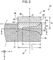
- Fig. 2 is a longitudinal sectional view of the front end portion 32 of the ground electrode 30.
- the longitudinal sectional view of Fig. 2 is a section that includes a center line C along a longitudinal direction of the ground electrode 30 and that is parallel to the axial line O.
- the center line C of the ground electrode 30 is a line that divides the ground electrode 30 in two in a width direction and that extends along the longitudinal direction of the ground electrode 30.
- the intermediate portion of the ground electrode 30 is bent so as to face the center electrode 20, with the longitudinal direction of the ground electrode 30 corresponding to the Y direction.
- the width direction of the ground electrode 30 is parallel to the X-axis direction.
- the Y-axis direction is perpendicular to the X-axis direction and the Z-axis direction, and is parallel to the longitudinal direction of the ground electrode 30.
- the ground electrode 30 includes an electrode base material 31, the discharge tip 80, and a melted portion 84.
- the discharge tip 80 is a clad member including a discharge layer 82 and an intermediate layer 83 that are joined to each other.
- the discharge tip 80 according to the embodiment has a columnar shape and a square-shaped surface 86 that faces the center electrode 20. In Fig. 2 and the descriptions that follow, the discharge tip 80 is such that the +Y direction corresponds to a front end 85 and the -Y direction corresponds to a back end 88.
- the discharge layer 82 is disposed adjacent to the center electrode 20.
- the discharge layer 82 contains a noble metal or a noble metal alloy, and is made of, for example, platinum (Pt), iridium (Ir), ruthenium (Ru), rhodium (Rh), or an alloy thereof.
- a first end of the intermediate layer 83 is joined to the discharge layer 82, and at least part of a second end of the intermediate layer 83 is welded to the electrode base material 31.
- the second end of the intermediate layer 83 shown in Fig. 2 also includes a boundary portion 36 between the intermediate layer 83 and the electrode base material 31.
- the intermediate layer 83 contains a noble metal element that is contained by the largest amount in the discharge layer 82, and an element that is contained in the electrode base material 31.
- the amount of noble metal element that is contained in the intermediate layer 83 is less than that contained in the discharge layer 82 in mass percentage. More specifically, for example, when the discharge layer 82 is made of a Pt-Ir based alloy, the intermediate layer 83 contains a smaller amount of Pt than the discharge layer 82 in mass percentage ratio; and, for example, a Pt-Ni based alloy containing nickel that is contained in the electrode base material 31 is used.
- a clad member including the discharge layer 82 and the intermediate layer 83 is formed by, for example, performing rolling while applying heat to the discharge layer 82 and the intermediate layer 83.
- the melted portion 84 is positioned near the boundary portion 36 between the intermediate layer 83 and the electrode base material 31.
- the melted portion 84 extends from a front-end-85 side of the discharge tip 80 (+Y direction) in a longitudinal direction (-Y direction) of the electrode base material 31.
- the melted portion 84 is formed by melting and solidifying the intermediate layer 83 and the electrode base material 31 by laser beam welding.
- the melted portion 84 contains a noble metal element that is contained in the intermediate layer 83 and an element that is contained in the electrode base material 31.
- the total amount of noble metal element in the melted portion 84 is, for example, 2.8 mass% or less.
- the melted portion 84 is a layer for reducing thermal stress that is generated when the spark plug 100 is used in addition to joining the discharge tip 80 to the electrode base material 31 by joining the intermediate layer 83 and the electrode base material 31 to each other.
- Fig. 2 also illustrates, along the axial line O, a height H1 of the discharge tip 80, a height H2 of the discharge layer 82, and a height H3 of the intermediate layer 83.
- Fig. 2 further illustrates a length T of the discharge tip 80 along the longitudinal direction of the ground electrode 30 (-Y direction) (hereunder referred to as the "length T"), and a length L of the melted portion 84 along a longitudinal direction thereof in a range in which the discharge tip 80 exists along the longitudinal direction (hereunder referred to as the "depth L").
- the depth L is also the length of the melted portion 84 towards the back end 88 of the discharge tip 80 from the front end 85 of the discharge tip 80 that is positioned at a second-end-35 side of the electrode base material 31.
- a proportion D of the depth L to the length T (hereunder referred to as the "proportion D") is greater than or equal to 76.2% and less than 100%.
- the height H1 of the discharge tip 80 is greater than or equal to 0.30 mm and less than or equal to 0.65 mm, and is 0.50 mm in the embodiment.
- the length T of the discharge tip 80 is greater than or equal to 1.0 mm and less than or equal to 2.0 mm, and is 1.8 mm in the embodiment.
- a ratio H1/T between the height H1 and the length T of the discharge tip 80 is greater than or equal to 0.20 and less than or equal to 0.45, and is 0.28 in the embodiment.
- a ratio H2/H3 between the height H2 of the discharge layer 82 and the height H3 of the intermediate layer 83 is greater than or equal to 0.30 and less than or equal to 2.05, and is 1.0 in the embodiment.
- the area of the surface 86 of the discharge tip 80 facing the center electrode 20 is greater than or equal to 0.75 mm 2 .
- Fig. 3 is a transverse sectional view of the front end portion 32 of the ground electrode 30.
- the transverse sectional view of Fig. 3 is a sectional view along A-A in Fig. 2 and includes the boundary portion 36.
- Fig. 3 illustrates the center P of the discharge tip 80, a straight line m that extends through the center P of the discharge tip 80 and that is parallel to the width direction (X-axis direction) of the ground electrode 30, the center line C of the ground electrode, and a region S (cross-hatched region) of the discharge tip 80 where the melted portion 84 is formed.
- the center P of the discharge tip 80 is also the center of the discharge layer 82.
- the melted portion 84 is also formed further beyond the straight line m in the -Y direction.
- the melted portion 84 is formed in at least the entire region on the second-end-35 side of the electrode base material 31 from the center P of the discharge tip 80 (region up to a depth T/2 of the discharge tip 80).
- the region S can be confirmed by observing the transverse section of the front end portion 32 of the ground electrode 30, the region S can also be confirmed by observing the discharge tip 80 from the -Z direction by using X rays (CT scan).
- the spark plug 100 is produced as follows. First, the metal shell 50, the insulator 10, the center electrode 20, and the electrode base material 31 are prepared. Then, the electrode base material 31 that has not been bent yet is joined to the metal shell 50. Independently of this, the center electrode 20 and the insulator 10 are assembled to each other. Then, an assembling step in which the insulator 10 to which the center electrode 20 has been assembled is assembled to the metal shell 50 to which the electrode base material 31 has been joined is performed. After the assembling step, a crimping step of the metal shell 50 is performed. By the crimping step, the insulator 10 is fixed to the metal shell 50. The gasket 5 is mounted between the sealing portion 54 and the mounting threaded portion 52 of the metal shell 50.
- the discharge tip 80 is welded to the electrode base material 31 by laser beam welding.
- the method of welding the electrode base material 31 and the discharge tip 80 by laser beam welding is described below.
- the ground electrode 30 is bent such that a side surface of the front end portion 32 of the ground electrode 30 faces the center electrode 20.
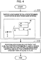
- Fig. 4 is a flow chart of a method of welding the electrode base material 31 and the discharge tip 80 to each other by laser beam welding.
- the discharge tip 80 is disposed on a predetermined location on the electrode base material 31 (Step S101).
- a depression 60 for disposing the discharge tip 80 is formed in the front end portion 32 of the electrode base material 31, and the discharge tip 80 is disposed in the depression 60 in the front end portion 32 of the discharge tip 80.
- the electrode base material 31 and the discharge tip 80 may be welded to each other by resistance welding for tentatively securing them, or may be secured to each other by using a jig.
- Step S103 a laser beam welding step in which the boundary portion 36 between the electrode base material 31 and the discharge tip 80 is irradiated with laser beams is performed.
- Fig. 5 is a schematic view of a state of the laser beam welding step.
- Fig. 5(a) is a view of the laser beam welding step when it is seen from the -X direction
- Fig. 5(b) is a view of the laser beam welding step when it is seen from the -Z direction.
- Step S103 as shown in Fig. 5(a) , the boundary portion 36 between the electrode base material 31 and the discharge tip 80 is irradiated with a laser beam LB that is parallel to the boundary portion 36 from the +Y direction, which corresponds to the second-end-35 side of the ground electrode 30.
- laser beams LB scan the entire end surface 85 of the discharge tip 80.
- the laser beams LB for example, fiber laser beams having high energy may be used.
- the laser beams LB need not illuminate the boundary portion 36 so as to be parallel to the boundary portion 36.
- the light beams LB may be tilted in a range of -5° to 5° in the Z direction with respect to the boundary portion 36 to illuminate the boundary portion 36.
- the melted portion 84 is formed by applying laser beams such that, when the discharge tip 80 is viewed from the -Z direction, the melted portion 84 is formed in at least a region on the second-end-35 side of the electrode base material 31 from the center P of the discharge tip 80, and such that the proportion D becomes greater than or equal to 76.2%.
- the spark plug 100 allows the depth of the melted portion 84 to be a sufficient depth in addition to allowing the melted portion 84 to be sufficiently formed in the region on the second-end-35 side of the electrode base material 31. Therefore, the spark plug 100 makes it possible to reduce warping of the discharge tip 80 including the discharge layer 82 and the intermediate layer 83 from the electrode base material 31. Consequently, it is possible to improve the anti-peeling performance of the discharge tip 80.
- the discharge tip 80 is a clad member including the discharge layer 82 and the intermediate layer 83, it is possible to increase the durability of the spark plug 100 by the discharge layer 82, and to reduce thermal stress that is generated due to a difference between the linear expansion coefficient of the discharge layer 82 and the linear expansion coefficient of the electrode base material 31 by the intermediate layer 83.
- the area of the surface 86 of the discharge tip 80 facing the center electrode 20 is greater than or equal to 0.75 mm 2 , it is possible to increase the durability of the spark plug 100.
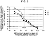
- Fig. 6 is a graph of the results of experiments carried out for determining an optimum range of proportion D.
- the output values of laser beams LB and the scan speeds of laser beams LB were changed to provide different proportions D.
- Three spark plugs having corresponding proportions D and discharge tips 80 with the following shapes and materials were produced.
- laser beams LB were applied such that, when each discharge tip 80 was viewed from the -Z direction, a melted portion 84 was formed in at least a region on a second-end-35 side of an electrode base material 31.
- the discharge tips 80 were discharge tips having the following three types of shapes and made of the following three types of materials.
- the electrode base materials 31 were made of Inconel 601.
- a thermal cyclic test was carried out.
- a front end portion 32 of each ground electrode 30 was heated for two minutes with a burner to raise the temperature of each ground electrode 30 to 1050°C.
- the burner was turned off, and each ground electrode 30 was slowly cooled for one minute and was reheated for two minutes with the burner to raise the temperature of each ground electrode 30 to 1050°C. This cycle was repeated 1000 times.
- each ground electrode 30 was cut into a section including a center line C thereof and being parallel to an axial line O.
- each section (longitudinal section shown in Fig. 2 )
- a proportion K of the sum of the lengths to a length T of the discharge tip was determined. The smaller the proportion K, the lower the possibility of peeling of the discharge tip 80 from the electrode base material 31.
- a proportion D of a depth L of each melted portion 84 to the length T of the corresponding discharge tip 80 was determined. Further, the proportion D and the proportion K of the three spark plugs produced under the same conditions were averaged to determine the relationship between the proportion D and the proportion K.
- the proportion K decreased. That is, as the length of each welded portion between the discharge tip 80 and the electrode base material 31 increased, the possibility of peeling of each discharge tip 80 from the corresponding electrode base material 31 decreased. In addition, it was found that when the proportion D became greater than or equal to 76.2%, the proportion K was significantly reduced than when the proportion D was less than 76.2%, so that the occurrence of an oxide scale and a crack was reduced to the extent allowing a reduction in the peeling of each discharge tip 80. The shapes of the discharge tips did not cause a significant difference between anti-peeling performances.
- FIG. 7 is a longitudinal sectional view of a front end portion 32a of a ground electrode 30a of a spark plug according to a second embodiment.
- the longitudinal sectional view shown in Fig. 7 is parallel to an axial line O and includes a center line C of the ground electrode 30.
- an end surface 87a of an intermediate layer 83a of a discharge tip 80a is exposed at a second-end-35a side of an electrode base material 31a.
- a melted portion 84a is formed in at least a region on the second-end-35a side of the electrode base material 31a from a center P of the discharge tip 80a (discharge layer 82a), and a proportion D of a depth L of the melted portion 84a is greater than or equal to 76.2%.
- the other structural features of the spark plug are the same as those of the spark plug 100 according to the first embodiment, and are thus not described.
- the ground electrode 30a where the end surface 87a is exposed on the second-end-35a side of the electrode base material 31a can be formed by adjusting as appropriate the output values of laser beams LB, the scan speed of the laser beams LB, and the irradiation angle of the laser beams LB with respect to a boundary portion 36a such that the end surface 87a is exposed in the above-described laser beam welding step (Step S103 in Fig. 4 ).
- the spark plug according to the second embodiment described above is such that when the discharge tip 80a is viewed from the -Z direction, the melted portion 84a is formed in at least the region on the second-end-35a side of the electrode base material 31a from the center P of the discharge tip 80a, and such that the proportion D of the depth L of the melted portion 84a to the length T of the discharge tip 80a is greater than or equal to 76.2%. Therefore, the same effects as those of the first embodiment are provided.
- the intermediate layer 83a contains a noble metal element that is contained by the largest amount in the discharge layer 82a, the intermediate layer 83a has higher anti-spark consumability than the melted portion 84a formed by melting the electrode base material 31a and the intermediate layer 83a.
- the end surface 87a of the intermediate layer 83a of the discharge tip 80a is exposed on the second-end-35a side of the electrode base material 31a. Therefore, even if a discharge occurs in the spark plug on a front-end-85a side of the discharge tip 80a, it is possible to further increase anti-spark consumability compared to that of the spark plug 100 according to the first embodiment in which the intermediate layer 83 is covered by the melted portion 84.
- Fig. 7 illustrates a state in which the end surface 87a of the intermediate layer 83a is exposed in the longitudinal section including the center line C of the ground electrode 30a.
- the spark plug is a spark plug in which the end surface 87a is exposed on the second-end-35a side of the electrode base material 31a, the same effects as those of the second embodiment are provided.
- the present invention is not limited to the above-described embodiments and modifications, so that various structures can be realized within a scope that does not depart from the gist of the present invention.
- any of the technical features in the embodiments and modifications corresponding to the technical features in the aspect and forms described in the "Summary of Invention" section may be replaced with another or may be combined with another as appropriate for solving some or all of the aforementioned problems or for realizing some or all of the aforementioned effects. If the technical features thereof are not described as being essential in the description, they may be omitted as appropriate.
Landscapes
- Spark Plugs (AREA)
Abstract
Description
- The present invention relates to a spark plug.
- Hitherto, a spark plug including a composite tip that includes two types of metals having different linear expansion coefficients and that is provided on an electrode has been known (see Patent Literature 1).
- PTL 1: Japanese Unexamined Patent Application Publication No.
H6-60959 - However, since the linear expansion coefficients differ, such a composite tip may be warped with respect to the electrode. Therefore, in such a spark plug including a composite tip, there is a demand for a technology that is capable of reducing warping of the composite tip with respect to an electrode material.
- The present invention is made for solving the above-described problem, and can be realized in the following forms.
- (1) According to an aspect of the present invention, there is provided a spark plug comprising a center electrode that extends in a direction of an axial line, an insulator having an axial hole for disposing the center electrode therein, a cylindrical metal shell that holds the insulator, and a ground electrode including an electrode base material whose first end portion is connected to a front end of the metal shell and a discharge tip that is joined to an inner side surface of a second end portion of the electrode base material and that faces the center electrode with a gap therebetween. In the spark plug, the discharge tip includes a discharge layer that is disposed adjacent to the center electrode and that contains a noble metal or a noble metal alloy, and an intermediate layer, a first end thereof being joined to the discharge layer and at least part of a second end thereof being joined to the electrode base material via a melted portion, the intermediate layer containing a noble metal element that is contained by a largest amount among noble metal elements that are contained in the discharge layer, an amount of the noble metal element that is contained in the intermediate layer being smaller than an amount of the noble metal element that is contained in the discharge layer, wherein when the discharge tip is viewed from the direction of the axial line, the melted portion is formed in at least a region on a second-end side of the electrode base material from a center of the discharge layer, and wherein in a section that includes a center line along a longitudinal direction of the ground electrode and that is parallel to the axial line, a proportion of a length of the melted portion along the longitudinal direction to a length of the discharge tip along the longitudinal direction is greater than or equal to 76.2%, with the length of the melted portion along the longitudinal direction being within a range in which the discharge tip exists along the longitudinal direction. According to the spark plug of such an aspect, the length of the melted portion can be a sufficient length. Therefore, it is possible to reduce warping of the discharge tip including the discharge layer and the intermediate layer from the electrode base material, and to improve the anti-peeling performance of the discharge tip.
- (2) In the spark plug of the aforementioned aspect, an end surface of the intermediate layer may be exposed on the second-end side of the electrode base material. According to the spark plug of such a form, an end surface of the intermediate layer is exposed on the second-end side of the electrode base material. Therefore, compared to a case in which an end surface of the intermediate layer is covered by the melted portion, it is possible to improve the anti-spark consumability of the discharge tip.
- (3) In the spark plug of the aforementioned aspect and form, an area of a surface of the discharge tip facing the center electrode may be greater than or equal to 0.75 mm2. According to the spark plug of such a form, it is possible to increase the durability of the spark plug.
- (4) In the spark plug of the aforementioned aspect and forms, the proportion may be greater than or equal to 100%. According to the spark plug of such a form, it is possible to reduce warping of the discharge tip including the discharge layer and the intermediate layer from the electrode base material, and to improve the anti-peeling performance of the discharge tip.
- The present invention may be realized in various forms other than in the forms of the above-described spark plugs, such as a method of producing a spark plug.
-
- [
Fig. 1] Fig. 1 is a partial sectional view of a spark plug according to an embodiment of the present invention. - [
Fig. 2] Fig. 2 is a longitudinal sectional view of a front end portion of a ground electrode. - [
Fig. 3] Fig. 3 is a transverse sectional view of the front end portion of the ground electrode. - [
Fig. 4] Fig. 4 is a flow chart of a method of welding an electrode base material and a discharge tip to each other by laser beam welding. - [
Fig. 5] Fig. 5 is a schematic view of a state of a laser beam welding step. - [
Fig. 6] Fig. 6 is a graph of the results of experiments carried out for determining an optimum range of a proportion D. - [
Fig. 7] Fig. 7 is a longitudinal sectional view of a front end portion of a ground electrode of a spark plug according to a second embodiment. - [
Fig. 8] Fig. 8 is a longitudinal sectional view of a front end portion of a ground electrode. - [
Fig. 9] Fig. 9 is a longitudinal sectional view of a front end portion of a ground electrode. - [
Fig. 10] Fig. 10 is a transverse sectional view of the front end portion of the ground electrode. - [
Fig. 11] Fig. 11 is a longitudinal sectional view of a front end portion of a ground electrode. - [
Fig. 12] Fig. 12 is a transverse sectional view of the front end portion of the ground electrode. - [
Fig. 13] Fig. 13 is a longitudinal sectional view of a front end portion of a ground electrode. - A. First Embodiment: A1. Structure of a spark plug:
Fig. 1 is a partial sectional view of aspark plug 100 according to an embodiment of the present invention. Thespark plug 100 has an elongated shape along an axial line O. InFig. 1 , the right side of the axial line O indicated by an alternate long and short dash line corresponds to an external front view, and the left side of the axial line O corresponds to a sectional view in which the axial line O extends. In the description below, the lower side inFig. 1 is called a front end side of thespark plug 100, and the upper side inFig. 1 is called a back end side. An X axis, a Y axis and a Z axis inFig. 1 corresponds to an X axis, a Y axis, and a Z axis in each of the other figures. The axial line O is parallel to the Z axis. InFig. 1 , the front end side of thespark plug 100 corresponds to a +Z direction, and the back end side of thespark plug 100 corresponds to a -Z direction. The term "Z direction" refers to directions parallel to the Z axis (directions along the Z axis). This similarly applies with regard to the X axis and the Y axis. - The
spark plug 100 includes aninsulator 10, acenter electrode 20, aground electrode 30, and ametal shell 50. At least part of an outer periphery of theinsulator 10 is held by thecylindrical metal shell 50. Theinsulator 10 has anaxial hole 12 along the axial line O. Thecenter electrode 20 is provided in theaxial hole 12. Theground electrode 30 is secured to afront end surface 57 of themetal shell 50. A discharge gap G is formed between theground electrode 30 and thecenter electrode 20. - The
insulator 10 is formed by sintering a ceramic material including alumina. Theinsulator 10 is a cylindrical member having theaxial hole 12 in the center thereof, a front end side of theaxial hole 12 accommodating part of thecenter electrode 20 and a back end side of theaxial hole 12 accommodating part of aterminal metal 40. Acenter body portion 19 having a large outside diameter is provided at the center of theinsulator 10 in an axial direction thereof. A back-end-side body portion 18 that insulates a portion between theterminal metal 40 and themetal shell 50 is provided closer to a terminal-metal-40 side than thecenter body portion 19. A front-end-side body portion 17 whose outside diameter is smaller than that of the back-end-side body portion 18 is provided closer to a center-electrode-20 side than thecenter body portion 19. An insulatornose length portion 13 whose outside diameter is smaller than that of the front-end-side body portion 17 and becomes smaller towards the center-electrode-20 side is provided beyond the front-end-side body portion 17. - The
metal shell 50 is a cylindrical metal shell that surrounds and holds a portion extending from part of the back-end-side body portion 18 of theinsulator 10 to the insulatornose length portion 13. Themetal shell 50 is made of, for example, low-carbon steel. Theentire metal shell 50 is plated with, for example, nickel or zinc. Themetal shell 50 includes atool engaging portion 51, a sealingportion 54, and a mounting threadedportion 52 in that order from the back end side. A tool for mounting thespark plug 100 on an engine head is fitted to thetool engaging portion 51. The mounting threadedportion 52 has a thread that is screwed into a mounting threaded hole in the engine head. The sealingportion 54 is provided in the form of a flange on a root of the mounting threadedportion 52. Anannular gasket 5, which is made from a bent plate material, is fitted to and inserted in a portion between the sealingportion 54 and the engine head. Thefront end surface 57 of themetal shell 50 is hollow and has a circular shape. The insulatornose length portion 13 of theinsulator 10 and thecenter electrode 20 project from the center of thefront end surface 57. - A thin crimping
portion 53 is provided closer to the back end side than thetool engaging portion 51 of themetal shell 50 is. Acompression deformation portion 58 that is thin as with the crimpingportion 53 is provided between the sealingportion 54 and thetool engaging portion 51.Ring members metal shell 50 and an outer peripheral surface of the back-end-side body portion 18 of theinsulator 10, from thetool engaging portion 51 to the crimpingportion 53. A portion between thering members spark plug 100, thecompression deformation portion 58 is compressed and deformed by pressing the crimpingportion 53 towards the front end side such that the crimpingportion 53 is inwardly bent. By compressing and deforming thecompression deformation portion 58, theinsulator 10 is pressed towards the front end side in themetal shell 50 via thering members talc 9. By the pressing, thetalc 9 is compressed in a direction of the axial line O to increase the airtightness in themetal shell 50. - At an inner periphery of the
metal shell 50, an insulator steppedportion 15 that is positioned at a base end of the insulatornose length portion 13 at theinsulator 10 is pressed against a metal shell inner steppedportion 56, which is provided at the mounting threadedportion 52, via an annular plate packing 8. The plate packing 8 is a material that maintains the airtightness between themetal shell 50 and theinsulator 10 and that prevents combustion gas from flowing out. - The
center electrode 20 is a bar-shaped member in which acore material 22 whose thermal conductivity is higher than that of a centerelectrode base material 21 is buried in the centerelectrode base material 21. The centerelectrode base material 21 is composed of a nickel alloy whose main component is nickel. Thecore material 22 is composed of copper or an alloy whose main component is copper. - A
flange 23 that projects towards an outer peripheral side is provided near a back end portion of thecenter electrode 20. Theflange 23 contacts, from the back end side, an axial hole inner steppedportion 14, which is formed at theaxial hole 12, to position thecenter electrode 20 in theinsulator 10. The back end portion of thecenter electrode 20 is electrically connected to theterminal metal 40 via aceramic resistor 3 and a sealingbody 4. - The
ground electrode 30 is made of a metal having high anticorrosiveness. Examples of metals having high anticorrosiveness include nickel alloys whose main component is nickel, such as Inconel (tradename) 600 and Inconel 601. Abase end of theground electrode 30 is welded to thefront end surface 57 of themetal shell 50. In the embodiment, an intermediate portion of theground electrode 30 is bent so that a side surface of a front end portion of theground electrode 30 faces thecenter electrode 20. A squarecolumnar discharge tip 80 that projects towards thecenter electrode 20, which is the other electrode, and that forms the discharge gap G is provided on an inner surface of a front end portion (second end portion) 32 of theground electrode 30. The axial line O inFig. 1 extends through a center P of thedischarge tip 80. -
Fig. 2 is a longitudinal sectional view of thefront end portion 32 of theground electrode 30. The longitudinal sectional view ofFig. 2 is a section that includes a center line C along a longitudinal direction of theground electrode 30 and that is parallel to the axial line O. The center line C of theground electrode 30 is a line that divides theground electrode 30 in two in a width direction and that extends along the longitudinal direction of theground electrode 30. In the embodiment, the intermediate portion of theground electrode 30 is bent so as to face thecenter electrode 20, with the longitudinal direction of theground electrode 30 corresponding to the Y direction. The width direction of theground electrode 30 is parallel to the X-axis direction. The Y-axis direction is perpendicular to the X-axis direction and the Z-axis direction, and is parallel to the longitudinal direction of theground electrode 30. Theground electrode 30 includes anelectrode base material 31, thedischarge tip 80, and a meltedportion 84. Thedischarge tip 80 is a clad member including adischarge layer 82 and anintermediate layer 83 that are joined to each other. Thedischarge tip 80 according to the embodiment has a columnar shape and a square-shapedsurface 86 that faces thecenter electrode 20. InFig. 2 and the descriptions that follow, thedischarge tip 80 is such that the +Y direction corresponds to afront end 85 and the -Y direction corresponds to aback end 88. - The
discharge layer 82 is disposed adjacent to thecenter electrode 20. Thedischarge layer 82 contains a noble metal or a noble metal alloy, and is made of, for example, platinum (Pt), iridium (Ir), ruthenium (Ru), rhodium (Rh), or an alloy thereof. A first end of theintermediate layer 83 is joined to thedischarge layer 82, and at least part of a second end of theintermediate layer 83 is welded to theelectrode base material 31. The second end of theintermediate layer 83 shown inFig. 2 also includes aboundary portion 36 between theintermediate layer 83 and theelectrode base material 31. Theintermediate layer 83 contains a noble metal element that is contained by the largest amount in thedischarge layer 82, and an element that is contained in theelectrode base material 31. The amount of noble metal element that is contained in theintermediate layer 83 is less than that contained in thedischarge layer 82 in mass percentage. More specifically, for example, when thedischarge layer 82 is made of a Pt-Ir based alloy, theintermediate layer 83 contains a smaller amount of Pt than thedischarge layer 82 in mass percentage ratio; and, for example, a Pt-Ni based alloy containing nickel that is contained in theelectrode base material 31 is used. Such a clad member including thedischarge layer 82 and theintermediate layer 83 is formed by, for example, performing rolling while applying heat to thedischarge layer 82 and theintermediate layer 83. - The melted
portion 84 is positioned near theboundary portion 36 between theintermediate layer 83 and theelectrode base material 31. The meltedportion 84 extends from a front-end-85 side of the discharge tip 80 (+Y direction) in a longitudinal direction (-Y direction) of theelectrode base material 31. The meltedportion 84 is formed by melting and solidifying theintermediate layer 83 and theelectrode base material 31 by laser beam welding. The meltedportion 84 contains a noble metal element that is contained in theintermediate layer 83 and an element that is contained in theelectrode base material 31. The total amount of noble metal element in the meltedportion 84 is, for example, 2.8 mass% or less. The meltedportion 84 is a layer for reducing thermal stress that is generated when thespark plug 100 is used in addition to joining thedischarge tip 80 to theelectrode base material 31 by joining theintermediate layer 83 and theelectrode base material 31 to each other. -
Fig. 2 also illustrates, along the axial line O, a height H1 of thedischarge tip 80, a height H2 of thedischarge layer 82, and a height H3 of theintermediate layer 83.Fig. 2 further illustrates a length T of thedischarge tip 80 along the longitudinal direction of the ground electrode 30 (-Y direction) (hereunder referred to as the "length T"), and a length L of the meltedportion 84 along a longitudinal direction thereof in a range in which thedischarge tip 80 exists along the longitudinal direction (hereunder referred to as the "depth L"). The depth L is also the length of the meltedportion 84 towards theback end 88 of thedischarge tip 80 from thefront end 85 of thedischarge tip 80 that is positioned at a second-end-35 side of theelectrode base material 31. In the embodiment, a proportion D of the depth L to the length T (hereunder referred to as the "proportion D") is greater than or equal to 76.2% and less than 100%. - The height H1 of the
discharge tip 80 is greater than or equal to 0.30 mm and less than or equal to 0.65 mm, and is 0.50 mm in the embodiment. The length T of thedischarge tip 80 is greater than or equal to 1.0 mm and less than or equal to 2.0 mm, and is 1.8 mm in the embodiment. A ratio H1/T between the height H1 and the length T of thedischarge tip 80 is greater than or equal to 0.20 and less than or equal to 0.45, and is 0.28 in the embodiment. A ratio H2/H3 between the height H2 of thedischarge layer 82 and the height H3 of theintermediate layer 83 is greater than or equal to 0.30 and less than or equal to 2.05, and is 1.0 in the embodiment. The area of thesurface 86 of thedischarge tip 80 facing thecenter electrode 20 is greater than or equal to 0.75 mm2. -
Fig. 3 is a transverse sectional view of thefront end portion 32 of theground electrode 30. The transverse sectional view ofFig. 3 is a sectional view along A-A inFig. 2 and includes theboundary portion 36.Fig. 3 illustrates the center P of thedischarge tip 80, a straight line m that extends through the center P of thedischarge tip 80 and that is parallel to the width direction (X-axis direction) of theground electrode 30, the center line C of the ground electrode, and a region S (cross-hatched region) of thedischarge tip 80 where the meltedportion 84 is formed. In the embodiment, the center P of thedischarge tip 80 is also the center of thedischarge layer 82. - As shown in
Fig. 3 , the meltedportion 84 is also formed further beyond the straight line m in the -Y direction. In other words, when thedischarge tip 80 is viewed from the - Z direction, the meltedportion 84 is formed in at least the entire region on the second-end-35 side of theelectrode base material 31 from the center P of the discharge tip 80 (region up to a depth T/2 of the discharge tip 80). Although, as shown inFig. 3 , the region S can be confirmed by observing the transverse section of thefront end portion 32 of theground electrode 30, the region S can also be confirmed by observing thedischarge tip 80 from the -Z direction by using X rays (CT scan). - In the embodiment, the
spark plug 100 is produced as follows. First, themetal shell 50, theinsulator 10, thecenter electrode 20, and theelectrode base material 31 are prepared. Then, theelectrode base material 31 that has not been bent yet is joined to themetal shell 50. Independently of this, thecenter electrode 20 and theinsulator 10 are assembled to each other. Then, an assembling step in which theinsulator 10 to which thecenter electrode 20 has been assembled is assembled to themetal shell 50 to which theelectrode base material 31 has been joined is performed. After the assembling step, a crimping step of themetal shell 50 is performed. By the crimping step, theinsulator 10 is fixed to themetal shell 50. Thegasket 5 is mounted between the sealingportion 54 and the mounting threadedportion 52 of themetal shell 50. - After the crimping step is performed, the
discharge tip 80 is welded to theelectrode base material 31 by laser beam welding. The method of welding theelectrode base material 31 and thedischarge tip 80 by laser beam welding is described below. After laser beam welding is performed, theground electrode 30 is bent such that a side surface of thefront end portion 32 of theground electrode 30 faces thecenter electrode 20. By performing the above, thespark plug 100 is completed. The above-described production method is one example. It is possible to produce the spark plug by performing various other methods that differ from the above-described method. For example, the order of the above-described steps can be changed at one's discretion. - A2. Method of welding the electrode base material and the discharge tip by laser beam welding:
Fig. 4 is a flow chart of a method of welding theelectrode base material 31 and thedischarge tip 80 to each other by laser beam welding. First, thedischarge tip 80 is disposed on a predetermined location on the electrode base material 31 (Step S101). In the embodiment, adepression 60 for disposing thedischarge tip 80 is formed in thefront end portion 32 of theelectrode base material 31, and thedischarge tip 80 is disposed in thedepression 60 in thefront end portion 32 of thedischarge tip 80. In Step S101, theelectrode base material 31 and thedischarge tip 80 may be welded to each other by resistance welding for tentatively securing them, or may be secured to each other by using a jig. - Next, a laser beam welding step in which the
boundary portion 36 between theelectrode base material 31 and thedischarge tip 80 is irradiated with laser beams is performed (Step S103). -
Fig. 5 is a schematic view of a state of the laser beam welding step.Fig. 5(a) is a view of the laser beam welding step when it is seen from the -X direction, andFig. 5(b) is a view of the laser beam welding step when it is seen from the -Z direction. In Step S103, as shown inFig. 5(a) , theboundary portion 36 between theelectrode base material 31 and thedischarge tip 80 is irradiated with a laser beam LB that is parallel to theboundary portion 36 from the +Y direction, which corresponds to the second-end-35 side of theground electrode 30. As shown inFig. 5(b) , laser beams LB scan theentire end surface 85 of thedischarge tip 80. As the laser beams LB, for example, fiber laser beams having high energy may be used. The laser beams LB need not illuminate theboundary portion 36 so as to be parallel to theboundary portion 36. For example, the light beams LB may be tilted in a range of -5° to 5° in the Z direction with respect to theboundary portion 36 to illuminate theboundary portion 36. - Accordingly, the melted
portion 84 is formed by applying laser beams such that, when thedischarge tip 80 is viewed from the -Z direction, the meltedportion 84 is formed in at least a region on the second-end-35 side of theelectrode base material 31 from the center P of thedischarge tip 80, and such that the proportion D becomes greater than or equal to 76.2%. It is possible to form such a meltedportion 84 by, with the relationships between laser output values, laser scan speed, the region S, and the proportion D being determined as a result of carrying out experiments, using laser power and scan speed that allow the region S to be formed in at least the region on the second-end-35 side of theelectrode base material 31 from the center P of thedischarge tip 80, and that allow the proportion D to become greater than or equal to 76.2%. - The
spark plug 100 according to the embodiment described above allows the depth of the meltedportion 84 to be a sufficient depth in addition to allowing the meltedportion 84 to be sufficiently formed in the region on the second-end-35 side of theelectrode base material 31. Therefore, thespark plug 100 makes it possible to reduce warping of thedischarge tip 80 including thedischarge layer 82 and theintermediate layer 83 from theelectrode base material 31. Consequently, it is possible to improve the anti-peeling performance of thedischarge tip 80. Since thedischarge tip 80 is a clad member including thedischarge layer 82 and theintermediate layer 83, it is possible to increase the durability of thespark plug 100 by thedischarge layer 82, and to reduce thermal stress that is generated due to a difference between the linear expansion coefficient of thedischarge layer 82 and the linear expansion coefficient of theelectrode base material 31 by theintermediate layer 83. - Since the area of the
surface 86 of thedischarge tip 80 facing thecenter electrode 20 is greater than or equal to 0.75 mm2, it is possible to increase the durability of thespark plug 100. - The grounds for forming the
spark plug 100 such that, when thedischarge tip 80 is viewed from the -Z direction, the meltedportion 84 is formed in at least a region on the second-end-35 side of theelectrode base material 31 from the center P of thedischarge tip 80, and such that the proportion D becomes greater than or equal to 76.2% are described below on the basis of the results of experiments. - A3. Content of experiments and results of experiments:
Fig. 6 is a graph of the results of experiments carried out for determining an optimum range of proportion D. In the experiments, in the above-described laser beam welding method (Step S103 inFig. 4 ), the output values of laser beams LB and the scan speeds of laser beams LB were changed to provide different proportions D. Three spark plugs having corresponding proportions D and dischargetips 80 with the following shapes and materials were produced. In the experiments, laser beams LB were applied such that, when eachdischarge tip 80 was viewed from the -Z direction, a meltedportion 84 was formed in at least a region on a second-end-35 side of anelectrode base material 31. Thedischarge tips 80 were discharge tips having the following three types of shapes and made of the following three types of materials. Theelectrode base materials 31 were made of Inconel 601. -
- <Discharge tip A> shape: cylindrical, area of a
surface 86 facing a center electrode: 0.79 mm2 (diameter 1.0 mm), material of discharge layer: Pt-Ir based alloy, material of intermediate layer: Pt-Ni based alloy. - <Discharge tip B> shape: square columnar, area of a
surface 86 facing a center electrode: 1.3 mm2, material of discharge layer: Pt-Ir based alloy, material of intermediate layer: Pt-Ni based alloy. - <Discharge tip C> shape: square columnar, area of a
surface 86 facing a center electrode 20: 1.5 mm2, material of discharge layer: Ir-based alloy, material of intermediate layer: Ir-Pt-Ni based alloy. - Next, in order to evaluate the relationships between each proportion D and the anti-peeling performance of its
corresponding discharge tip 80, a thermal cyclic test was carried out. In the thermal cyclic test, first, afront end portion 32 of eachground electrode 30 was heated for two minutes with a burner to raise the temperature of eachground electrode 30 to 1050°C. Thereafter, the burner was turned off, and eachground electrode 30 was slowly cooled for one minute and was reheated for two minutes with the burner to raise the temperature of eachground electrode 30 to 1050°C. This cycle was repeated 1000 times. - Next, each
ground electrode 30 was cut into a section including a center line C thereof and being parallel to an axial line O. In each section (longitudinal section shown inFig. 2 ), the sum of the length of aboundary portion 36 where theintermediate layer 83 and theelectrode base material 31 were not melted and the length of an oxide scale and a crack in the meltedportion 84 occurring near theboundary portion 36 was measured. In eachspark plug 100, a proportion K of the sum of the lengths to a length T of the discharge tip was determined. The smaller the proportion K, the lower the possibility of peeling of thedischarge tip 80 from theelectrode base material 31. In addition, a proportion D of a depth L of each meltedportion 84 to the length T of thecorresponding discharge tip 80 was determined. Further, the proportion D and the proportion K of the three spark plugs produced under the same conditions were averaged to determine the relationship between the proportion D and the proportion K. - As shown in
Fig. 6 , as the proportion D increased, the proportion K decreased. That is, as the length of each welded portion between thedischarge tip 80 and theelectrode base material 31 increased, the possibility of peeling of eachdischarge tip 80 from the correspondingelectrode base material 31 decreased. In addition, it was found that when the proportion D became greater than or equal to 76.2%, the proportion K was significantly reduced than when the proportion D was less than 76.2%, so that the occurrence of an oxide scale and a crack was reduced to the extent allowing a reduction in the peeling of eachdischarge tip 80. The shapes of the discharge tips did not cause a significant difference between anti-peeling performances. - The aforementioned results show that it is desirable that, when each
discharge tip 80 is viewed from the -Z direction, the meltedportion 84 be formed in at least a region on the second-end-35 side of theelectrode base material 31 from a center P of thedischarge tip 80 and that the proportion D of the depth L of the meltedportion 84 to the length T of thedischarge tip 80 be greater than or equal to 76.2%. - B. Second Embodiment: B1. Structure of a spark plug:
Fig. 7 is a longitudinal sectional view of afront end portion 32a of aground electrode 30a of a spark plug according to a second embodiment. The longitudinal sectional view shown inFig. 7 is parallel to an axial line O and includes a center line C of theground electrode 30. In theground electrode 30a according to the embodiment, anend surface 87a of anintermediate layer 83a of adischarge tip 80a is exposed at a second-end-35a side of anelectrode base material 31a. Even in the spark plug according to this embodiment, as in the spark plug according to the first embodiment, when thedischarge tip 80a is viewed from the -Z direction, a meltedportion 84a is formed in at least a region on the second-end-35a side of theelectrode base material 31a from a center P of thedischarge tip 80a (discharge layer 82a), and a proportion D of a depth L of the meltedportion 84a is greater than or equal to 76.2%. The other structural features of the spark plug are the same as those of thespark plug 100 according to the first embodiment, and are thus not described. - The
ground electrode 30a where theend surface 87a is exposed on the second-end-35a side of theelectrode base material 31a can be formed by adjusting as appropriate the output values of laser beams LB, the scan speed of the laser beams LB, and the irradiation angle of the laser beams LB with respect to aboundary portion 36a such that theend surface 87a is exposed in the above-described laser beam welding step (Step S103 inFig. 4 ). - The spark plug according to the second embodiment described above is such that when the
discharge tip 80a is viewed from the -Z direction, the meltedportion 84a is formed in at least the region on the second-end-35a side of theelectrode base material 31a from the center P of thedischarge tip 80a, and such that the proportion D of the depth L of the meltedportion 84a to the length T of thedischarge tip 80a is greater than or equal to 76.2%. Therefore, the same effects as those of the first embodiment are provided. - Since the
intermediate layer 83a contains a noble metal element that is contained by the largest amount in thedischarge layer 82a, theintermediate layer 83a has higher anti-spark consumability than the meltedportion 84a formed by melting theelectrode base material 31a and theintermediate layer 83a. In the spark plug according to the second embodiment, theend surface 87a of theintermediate layer 83a of thedischarge tip 80a is exposed on the second-end-35a side of theelectrode base material 31a. Therefore, even if a discharge occurs in the spark plug on a front-end-85a side of thedischarge tip 80a, it is possible to further increase anti-spark consumability compared to that of thespark plug 100 according to the first embodiment in which theintermediate layer 83 is covered by the meltedportion 84. -
Fig. 7 illustrates a state in which theend surface 87a of theintermediate layer 83a is exposed in the longitudinal section including the center line C of theground electrode 30a. However, as long as the spark plug is a spark plug in which theend surface 87a is exposed on the second-end-35a side of theelectrode base material 31a, the same effects as those of the second embodiment are provided. - C. Modifications: C1. First modification: In the above-described various embodiments, the
discharge tip 80 includes onedischarge layer 82 and oneintermediate layer 83, and thedischarge tip 80a includes onedischarge layer 82a and oneintermediate layer 83a. In contrast, adischarge tip 80c may include two or more intermediate layers.
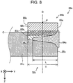
Fig. 8 is a longitudinal sectional view of afront end portion 32c of aground electrode 30c. In theground electrode 30c shown inFig. 8 , thedischarge tip 80c includes adischarge layer 82c, a firstintermediate layer 83b, and a secondintermediate layer 83c. The firstintermediate layer 83b contains a noble metal element (such as Pt) that is contained by the largest amount in thedischarge layer 82c, and an element (such as Ni) that is contained in anelectrode base material 31c. The secondintermediate layer 83c contains the noble metal element (such as Pt) that is contained by the largest amount in thedischarge layer 82c by an amount that is smaller than the amount of the noble metal element that is contained in the firstintermediate layer 83b. The secondintermediate layer 83c contains the element (such as Ni) that is contained in theelectrode base material 31c by an amount that is larger than the amount of the element that is contained in the firstintermediate layer 83b.
Such adischarge tip 80c is such that the secondintermediate layer 83c contains an element (such as Ni) contained in theelectrode base material 31c by an amount that is larger than the amount of the element that is contained in the firstintermediate layer 83b. Therefore, compared to when a discharge tip includes only the firstintermediate layer 83b, thedischarge tip 80c tends to be melted due to theelectrode base material 31c. Therefore, a proportion D of a depth L of a meltedportion 84c is a sufficient proportion, so that it is possible to improve the anti-peeling performance of thedischarge tip 80c. In addition, compared to when a discharge tip only includes the firstintermediate layer 83b, the amount of noble metal element that is used in thedischarge tip 80c can be reduced, so that the costs of producing spark plugs can be reduced. - C2. Second modification: In the above-described various embodiments, The
columnar discharge tips surfaces 86 and 86a, respectively, that face thecenter electrode 20. Thesurfaces 86 and 86a of thecorresponding discharge tips discharge tips
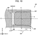
Fig. 9 is a longitudinal sectional view of afront end portion 32f of aground electrode 30f. The longitudinal sectional view shown inFig. 9 is parallel to an axial line O and includes a center line C of theground electrode 30f.Fig. 10 is a transverse sectional view of thefront end portion 32f of theground electrode 30f.Fig. 10 is a sectional view along B-B inFig. 9 and includes aboundary portion 36f. Adischarge tip 80f shown inFigs. 9 and10 has a columnar shape, and asurface 86f thereof facing acenter electrode 20 has a rectangular shape. Even in thedischarge tip 80f having such a shape, as shown inFig. 9 , as long as a proportion D of a depth L of a meltedportion 84f to a length T is greater than or equal to 76.2%.; and, as shown inFig. 10 , as long as, when thedischarge tip 80f is viewed from the -Z direction, the meltedportion 84f is formed in at least a region on a second-end-35f side of anelectrode base material 31f from a center P of thedischarge tip 80f (discharge layer 82f), the same effects as those according to the above-described first embodiment are provided. - C3. Third modification: In the above-described various embodiments, the
second end 35 of theground electrode 30 and thefront end 85 of thedischarge tip 80 are aligned with each other, and thesecond end 35a of theground electrode 30a and thefront end 85a of thedischarge tip 80a are aligned with each other. In addition, thesecond end 35 and thefront end 85 and thesecond end 35a and thefront end 85a are positioned in the same XZ plane. However, thesecond end 35 of theground electrode 30 and thefront end 85 of thedischarge tip 80 need not be aligned with other; and thesecond end 35a of theground electrode 30a and thefront end 85a of thedischarge tip 80a need not be aligned with each other.
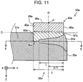
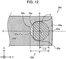
Fig. 11 is a longitudinal sectional view of afront end portion 32e of aground electrode 30e. The longitudinal sectional view shown inFig. 11 is parallel to an axial line O and includes a center line C of theground electrode 30e.Fig. 12 is a transverse sectional view of thefront end portion 32e of theground electrode 30e.Fig. 12 is a sectional view along E-E inFig. 11 and includes aboundary portion 36e. In theground electrode 30e, asecond end 35e of theground electrode 30e and afront end 85e of adischarge tip 80e are not aligned with each other and are thus not positioned in the same XZ plane. As shown inFig. 11 , a meltedportion 84 is such that a proportion D of a depth L is greater than or equal to 76.2%. Anend surface 87e of anintermediate layer 83e is exposed. Further, as shown inFig. 12 , when thedischarge tip 80e is viewed from the -Z direction, a meltedportion 84e is formed in at least a region on a second-end-35e side of anelectrode base material 31e from a center P of thedischarge tip 80e (discharge layer 82e). Even such a spark plug including theground electrode 30e provides the same effects as those of the above-described second embodiment. - C4. Fourth modification: In the above-described various embodiments, the
discharge tip 80 is welded to thedepression 60 of theelectrode base material 31 by laser beam welding, and thedischarge tip 80a is welded to thedepression 60 of theelectrode base material 31a by laser beam welding. However, thedischarge tip 80 may be directly welded to a flat surface of theelectrode base material 31 without forming thedepression 60 in theelectrode base material 31, and thedischarge tip 80a may be directly welded to a flat surface of theelectrode base material 31a without forming thedepression 60 in theelectrode base material 31a. - C5. Fifth modification: In each of the above-described various embodiments, the proportion D of the depth L of the melted portion is greater than or equal to 76.2% and less than 100%. However, the proportion D may be greater than or equal to 100%.
Fig. 13 is a longitudinal sectional view of afront end portion 32d of aground electrode 30d. The longitudinal sectional view shown inFig. 13 is parallel to an axial line O and includes a center line C of theground electrode 30d. In theground electrode 30d shown inFig. 13 , a proportion D of a depth L is greater than or equal to 100%. As with theground electrode 30d shown inFig. 13 , when a boundary portion between adischarge tip 80d and anelectrode base material 31d in longitudinal section cannot be seen, a length T of thedischarge tip 80d may be measured by measuring a length T of thedischarge tip 80 corresponding to the boundary portion (a maximum length of thedischarge tip 80d along the longitudinal direction). A depth L of a meltedportion 84d may be measured by measuring a length L towards aback end 88d from afront end 85d of thedischarge tip 80d along the longitudinal direction. Although not illustrated, when thedischarge tip 80d is viewed from the -Z direction, the meltedportion 84d is formed in at least a region on a second-end-35d side of theelectrode base material 31d from a center P of thedischarge tip 80d.
In this way, when the proportion D is greater than or equal to 100%, it is possible to reduce warping of thedischarge tip 80d from theelectrode base material 31d, and to improve the anti-peeling performance of thedischarge tip 80d. - C6. Sixth modification: In the above-described first embodiment, the area of the
surface 86 of thedischarge tip 80 facing thecenter electrode 20 is greater than or equal to 0.75 mm2. In contrast, the area of thesurface 86 may be less than 0.75 mm2. - The present invention is not limited to the above-described embodiments and modifications, so that various structures can be realized within a scope that does not depart from the gist of the present invention. For example, any of the technical features in the embodiments and modifications corresponding to the technical features in the aspect and forms described in the "Summary of Invention" section may be replaced with another or may be combined with another as appropriate for solving some or all of the aforementioned problems or for realizing some or all of the aforementioned effects. If the technical features thereof are not described as being essential in the description, they may be omitted as appropriate.
-
- 3 ceramic resistor
- 4 sealing body
- 5 gasket
- 6 ring member
- 8 plate packing
- 9 talc
- 10 insulator
- 12 axial hole
- 13 insulator nose length portion
- 14 axial hole inner stepped portion
- 15 insulator stepped portion
- 17 front-end-side body portion
- 18 back-end-side body portion
- 19 center body portion
- 20 center electrode
- 21 center electrode base material
- 22 core material
- 23 flange
- 30, 30a, 30c, 30d, 30e, 30f ground electrode
- 31, 31a, 31c, 31d, 31e, 31f electrode base material
- 32, 32a, 32c, 32d, 32e, 32f front end portion
- 35, 35a, 35e second end
- 36, 36a, 36e, 36f boundary portion
- 40 terminal metal
- 50 metal shell
- 51 tool engaging portion
- 52 mounting threaded portion
- 53 crimping portion
- 54 sealing portion
- 56 metal shell inner stepped portion
- 57 front end surface
- 58 compression deformation portion
- 60 depression
- 80, 80a, 80c, 80d, 80e, 80f discharge tip
- 82, 82a, 82c, 82d, 82e, 82f discharge layer
- 83, 83a, 83e intermediate layer
- 83b first intermediate layer
- 83c second intermediate layer
- 84, 84a, 84c, 84d, 84f melted portion
- 85, 85d, 85e front end of discharge tip
- 86, 86f surface of discharge tip facing center electrode
- 87a, 87e end surface of intermediate layer
- 88, 88d back end of discharge tip
- 100 spark plug
- C center line of ground electrode
- G discharge gap
- LB laser beam
- O axial line
- P center of discharge layer
- S region
- m straight line
Claims (4)
- A spark plug comprising a center electrode that extends in a direction of an axial line, an insulator having an axial hole for disposing the center electrode therein, a cylindrical metal shell that holds the insulator, and a ground electrode including an electrode base material whose first end portion is connected to a front end of the metal shell and a discharge tip that is joined to an inner side surface of a second end portion of the electrode base material and that faces the center electrode with a gap therebetween,
wherein the discharge tip includesa discharge layer that is disposed adjacent to the center electrode and that contains a noble metal or a noble metal alloy, andan intermediate layer, a first end thereof being joined to the discharge layer and at least part of a second end thereof being joined to the electrode base material via a melted portion, the intermediate layer containing a noble metal element that is contained by a largest amount among noble metal elements that are contained in the discharge layer, an amount of the noble metal element that is contained in the intermediate layer being smaller than an amount of the noble metal element that is contained in the discharge layer,wherein when the discharge tip is viewed from the direction of the axial line, the melted portion is formed in at least a region on a second-end side of the electrode base material from a center of the discharge layer, and
wherein in a section that includes a center line along a longitudinal direction of the ground electrode and that is parallel to the axial line, a proportion of a length of the melted portion along the longitudinal direction to a length of the discharge tip along the longitudinal direction is greater than or equal to 76.2%, with the length of the melted portion along the longitudinal direction being within a range in which the discharge tip exists along the longitudinal direction. - The spark plug according to Claim 1, wherein an end surface of the intermediate layer is exposed on the second-end side of the electrode base material.
- The spark plug according to either Claim 1 or Claim 2, wherein an area of a surface of the discharge tip facing the center electrode is greater than or equal to 0.75 mm2.
- The spark plug according to any one of Claims 1 to 3, wherein the proportion is greater than or equal to 100%.
Applications Claiming Priority (2)
| Application Number | Priority Date | Filing Date | Title |
|---|---|---|---|
| JP2015174520A JP6105694B2 (en) | 2015-09-04 | 2015-09-04 | Spark plug |
| PCT/JP2016/002771 WO2017037969A1 (en) | 2015-09-04 | 2016-06-08 | Spark plug |
Publications (2)
| Publication Number | Publication Date |
|---|---|
| EP3346559A1 true EP3346559A1 (en) | 2018-07-11 |
| EP3346559A4 EP3346559A4 (en) | 2019-04-17 |
Family
ID=58186779
Family Applications (1)
| Application Number | Title | Priority Date | Filing Date |
|---|---|---|---|
| EP16841017.3A Withdrawn EP3346559A4 (en) | 2015-09-04 | 2016-06-08 | IGNITION CANDLE |
Country Status (6)
| Country | Link |
|---|---|
| US (1) | US10181702B2 (en) |
| EP (1) | EP3346559A4 (en) |
| JP (1) | JP6105694B2 (en) |
| KR (1) | KR20180037007A (en) |
| CN (1) | CN107925221A (en) |
| WO (1) | WO2017037969A1 (en) |
Families Citing this family (3)
| Publication number | Priority date | Publication date | Assignee | Title |
|---|---|---|---|---|
| JP6793154B2 (en) * | 2018-06-13 | 2020-12-02 | 日本特殊陶業株式会社 | Spark plug |
| JP7228044B2 (en) * | 2019-11-29 | 2023-02-22 | 日本特殊陶業株式会社 | Spark plug |
| JP7121081B2 (en) * | 2020-08-19 | 2022-08-17 | 日本特殊陶業株式会社 | Spark plug |
Family Cites Families (15)
| Publication number | Priority date | Publication date | Assignee | Title |
|---|---|---|---|---|
| JPS59160988A (en) | 1983-03-02 | 1984-09-11 | 日本特殊陶業株式会社 | Spark plug |
| JPS61135080A (en) * | 1984-12-05 | 1986-06-23 | 日本特殊陶業株式会社 | Spark plug |
| JPS61135081A (en) * | 1984-12-06 | 1986-06-23 | 日本特殊陶業株式会社 | Spark plug |
| US5465022A (en) | 1992-08-12 | 1995-11-07 | Nippondenso Co., Ltd. | Spark plug for internal-combustion engine and manufacture method of the same |
| JP3724815B2 (en) | 1992-08-12 | 2005-12-07 | 株式会社デンソー | Spark plug for internal combustion engine |
| JP5113161B2 (en) * | 2007-11-15 | 2013-01-09 | 日本特殊陶業株式会社 | Spark plug |
| WO2009081563A1 (en) * | 2007-12-20 | 2009-07-02 | Ngk Spark Plug Co., Ltd. | Spark plug and process for producing the spark plug |
| JP4705129B2 (en) * | 2008-05-21 | 2011-06-22 | 日本特殊陶業株式会社 | Spark plug |
| US8648519B2 (en) * | 2008-11-21 | 2014-02-11 | Ngk Spark Plug Co., Ltd. | Spark plug for internal combustion engine |
| JP4619443B2 (en) * | 2009-03-31 | 2011-01-26 | 日本特殊陶業株式会社 | Spark plug |
| WO2012042801A1 (en) * | 2010-09-29 | 2012-04-05 | 日本特殊陶業株式会社 | Spark plug |
| WO2012067199A1 (en) * | 2010-11-17 | 2012-05-24 | 日本特殊陶業株式会社 | Spark plug |
| JP5835704B2 (en) * | 2011-08-03 | 2015-12-24 | 日本特殊陶業株式会社 | Spark plug |
| JP5642032B2 (en) * | 2011-08-17 | 2014-12-17 | 日本特殊陶業株式会社 | Spark plug |
| US9368943B2 (en) * | 2013-03-12 | 2016-06-14 | Federal-Mogul Ignition Company | Spark plug having multi-layer sparking component attached to ground electrode |
-
2015
- 2015-09-04 JP JP2015174520A patent/JP6105694B2/en not_active Expired - Fee Related
-
2016
- 2016-06-08 KR KR1020187005960A patent/KR20180037007A/en not_active Abandoned
- 2016-06-08 CN CN201680051036.XA patent/CN107925221A/en active Pending
- 2016-06-08 US US15/755,746 patent/US10181702B2/en not_active Expired - Fee Related
- 2016-06-08 WO PCT/JP2016/002771 patent/WO2017037969A1/en not_active Ceased
- 2016-06-08 EP EP16841017.3A patent/EP3346559A4/en not_active Withdrawn
Also Published As
| Publication number | Publication date |
|---|---|
| US10181702B2 (en) | 2019-01-15 |
| CN107925221A (en) | 2018-04-17 |
| EP3346559A4 (en) | 2019-04-17 |
| JP6105694B2 (en) | 2017-03-29 |
| JP2017050234A (en) | 2017-03-09 |
| US20180248340A1 (en) | 2018-08-30 |
| WO2017037969A1 (en) | 2017-03-09 |
| KR20180037007A (en) | 2018-04-10 |
Similar Documents
| Publication | Publication Date | Title |
|---|---|---|
| JP5119268B2 (en) | Spark plug and manufacturing method thereof | |
| US8640666B2 (en) | Spark plug for internal combustion engine | |
| US20100264801A1 (en) | Spark plug and process for producing the spark plug | |
| US9742158B2 (en) | Spark plug | |
| EP2704271B1 (en) | Spark plug | |
| KR101513325B1 (en) | Spark plug for internal combustion engine | |
| US9065255B2 (en) | Spark plug and method of manufacturing the same | |
| US10181702B2 (en) | Spark plug | |
| JP5642032B2 (en) | Spark plug | |
| CN101447650B (en) | Spark plug for internal combustion engine | |
| EP2963745B1 (en) | Spark plug | |
| US9197038B1 (en) | Spark plug and method of manufacturing the same | |
| US9614353B2 (en) | Spark plug | |
| US9948068B2 (en) | Spark plug | |
| US8946976B2 (en) | Spark plug | |
| EP3200290B1 (en) | Spark plug | |
| EP3220496B1 (en) | Ignition plug | |
| JP5890368B2 (en) | Spark plug | |
| JP6234956B2 (en) | Manufacturing method of spark plug | |
| JP5498432B2 (en) | Manufacturing method of spark plug | |
| JP2017054599A (en) | Spark plug and manufacturing method thereof | |
| JP2017111983A (en) | Spark plug |
Legal Events
| Date | Code | Title | Description |
|---|---|---|---|
| STAA | Information on the status of an ep patent application or granted ep patent |
Free format text: STATUS: THE INTERNATIONAL PUBLICATION HAS BEEN MADE |
|
| PUAI | Public reference made under article 153(3) epc to a published international application that has entered the european phase |
Free format text: ORIGINAL CODE: 0009012 |
|
| STAA | Information on the status of an ep patent application or granted ep patent |
Free format text: STATUS: REQUEST FOR EXAMINATION WAS MADE |
|
| 17P | Request for examination filed |
Effective date: 20180302 |
|
| AK | Designated contracting states |
Kind code of ref document: A1 Designated state(s): AL AT BE BG CH CY CZ DE DK EE ES FI FR GB GR HR HU IE IS IT LI LT LU LV MC MK MT NL NO PL PT RO RS SE SI SK SM TR |
|
| AX | Request for extension of the european patent |
Extension state: BA ME |
|
| DAV | Request for validation of the european patent (deleted) | ||
| DAX | Request for extension of the european patent (deleted) | ||
| A4 | Supplementary search report drawn up and despatched |
Effective date: 20190320 |
|
| RIC1 | Information provided on ipc code assigned before grant |
Ipc: H01T 13/39 20060101ALI20190314BHEP Ipc: H01T 13/32 20060101AFI20190314BHEP |
|
| STAA | Information on the status of an ep patent application or granted ep patent |
Free format text: STATUS: THE APPLICATION HAS BEEN WITHDRAWN |
|
| 18W | Application withdrawn |
Effective date: 20200827 |