EP3346541A1 - Cell agnostic battery pack - Google Patents
Cell agnostic battery pack Download PDFInfo
- Publication number
- EP3346541A1 EP3346541A1 EP18150847.4A EP18150847A EP3346541A1 EP 3346541 A1 EP3346541 A1 EP 3346541A1 EP 18150847 A EP18150847 A EP 18150847A EP 3346541 A1 EP3346541 A1 EP 3346541A1
- Authority
- EP
- European Patent Office
- Prior art keywords
- sub
- modules
- battery pack
- type
- pack controller
- Prior art date
- Legal status (The legal status is an assumption and is not a legal conclusion. Google has not performed a legal analysis and makes no representation as to the accuracy of the status listed.)
- Granted
Links
Images




Classifications
-
- H—ELECTRICITY
- H01—ELECTRIC ELEMENTS
- H01M—PROCESSES OR MEANS, e.g. BATTERIES, FOR THE DIRECT CONVERSION OF CHEMICAL ENERGY INTO ELECTRICAL ENERGY
- H01M10/00—Secondary cells; Manufacture thereof
- H01M10/42—Methods or arrangements for servicing or maintenance of secondary cells or secondary half-cells
- H01M10/425—Structural combination with electronic components, e.g. electronic circuits integrated to the outside of the casing
-
- G—PHYSICS
- G01—MEASURING; TESTING
- G01R—MEASURING ELECTRIC VARIABLES; MEASURING MAGNETIC VARIABLES
- G01R31/00—Arrangements for testing electric properties; Arrangements for locating electric faults; Arrangements for electrical testing characterised by what is being tested not provided for elsewhere
- G01R31/36—Arrangements for testing, measuring or monitoring the electrical condition of accumulators or electric batteries, e.g. capacity or state of charge [SoC]
- G01R31/382—Arrangements for monitoring battery or accumulator variables, e.g. SoC
-
- H—ELECTRICITY
- H01—ELECTRIC ELEMENTS
- H01M—PROCESSES OR MEANS, e.g. BATTERIES, FOR THE DIRECT CONVERSION OF CHEMICAL ENERGY INTO ELECTRICAL ENERGY
- H01M10/00—Secondary cells; Manufacture thereof
- H01M10/05—Accumulators with non-aqueous electrolyte
- H01M10/052—Li-accumulators
- H01M10/0525—Rocking-chair batteries, i.e. batteries with lithium insertion or intercalation in both electrodes; Lithium-ion batteries
-
- H—ELECTRICITY
- H01—ELECTRIC ELEMENTS
- H01M—PROCESSES OR MEANS, e.g. BATTERIES, FOR THE DIRECT CONVERSION OF CHEMICAL ENERGY INTO ELECTRICAL ENERGY
- H01M10/00—Secondary cells; Manufacture thereof
- H01M10/42—Methods or arrangements for servicing or maintenance of secondary cells or secondary half-cells
- H01M10/48—Accumulators combined with arrangements for measuring, testing or indicating the condition of cells, e.g. the level or density of the electrolyte
-
- H—ELECTRICITY
- H01—ELECTRIC ELEMENTS
- H01M—PROCESSES OR MEANS, e.g. BATTERIES, FOR THE DIRECT CONVERSION OF CHEMICAL ENERGY INTO ELECTRICAL ENERGY
- H01M10/00—Secondary cells; Manufacture thereof
- H01M10/42—Methods or arrangements for servicing or maintenance of secondary cells or secondary half-cells
- H01M10/48—Accumulators combined with arrangements for measuring, testing or indicating the condition of cells, e.g. the level or density of the electrolyte
- H01M10/482—Accumulators combined with arrangements for measuring, testing or indicating the condition of cells, e.g. the level or density of the electrolyte for several batteries or cells simultaneously or sequentially
-
- G—PHYSICS
- G01—MEASURING; TESTING
- G01R—MEASURING ELECTRIC VARIABLES; MEASURING MAGNETIC VARIABLES
- G01R31/00—Arrangements for testing electric properties; Arrangements for locating electric faults; Arrangements for electrical testing characterised by what is being tested not provided for elsewhere
- G01R31/36—Arrangements for testing, measuring or monitoring the electrical condition of accumulators or electric batteries, e.g. capacity or state of charge [SoC]
- G01R31/396—Acquisition or processing of data for testing or for monitoring individual cells or groups of cells within a battery
-
- H—ELECTRICITY
- H01—ELECTRIC ELEMENTS
- H01M—PROCESSES OR MEANS, e.g. BATTERIES, FOR THE DIRECT CONVERSION OF CHEMICAL ENERGY INTO ELECTRICAL ENERGY
- H01M10/00—Secondary cells; Manufacture thereof
- H01M10/05—Accumulators with non-aqueous electrolyte
- H01M10/052—Li-accumulators
-
- H—ELECTRICITY
- H01—ELECTRIC ELEMENTS
- H01M—PROCESSES OR MEANS, e.g. BATTERIES, FOR THE DIRECT CONVERSION OF CHEMICAL ENERGY INTO ELECTRICAL ENERGY
- H01M10/00—Secondary cells; Manufacture thereof
- H01M10/60—Heating or cooling; Temperature control
- H01M10/65—Means for temperature control structurally associated with the cells
- H01M10/656—Means for temperature control structurally associated with the cells characterised by the type of heat-exchange fluid
- H01M10/6561—Gases
- H01M10/6563—Gases with forced flow, e.g. by blowers
-
- H—ELECTRICITY
- H01—ELECTRIC ELEMENTS
- H01M—PROCESSES OR MEANS, e.g. BATTERIES, FOR THE DIRECT CONVERSION OF CHEMICAL ENERGY INTO ELECTRICAL ENERGY
- H01M10/00—Secondary cells; Manufacture thereof
- H01M10/42—Methods or arrangements for servicing or maintenance of secondary cells or secondary half-cells
- H01M10/425—Structural combination with electronic components, e.g. electronic circuits integrated to the outside of the casing
- H01M2010/4271—Battery management systems including electronic circuits, e.g. control of current or voltage to keep battery in healthy state, cell balancing
-
- H—ELECTRICITY
- H01—ELECTRIC ELEMENTS
- H01M—PROCESSES OR MEANS, e.g. BATTERIES, FOR THE DIRECT CONVERSION OF CHEMICAL ENERGY INTO ELECTRICAL ENERGY
- H01M10/00—Secondary cells; Manufacture thereof
- H01M10/42—Methods or arrangements for servicing or maintenance of secondary cells or secondary half-cells
- H01M10/425—Structural combination with electronic components, e.g. electronic circuits integrated to the outside of the casing
- H01M2010/4278—Systems for data transfer from batteries, e.g. transfer of battery parameters to a controller, data transferred between battery controller and main controller
-
- Y—GENERAL TAGGING OF NEW TECHNOLOGICAL DEVELOPMENTS; GENERAL TAGGING OF CROSS-SECTIONAL TECHNOLOGIES SPANNING OVER SEVERAL SECTIONS OF THE IPC; TECHNICAL SUBJECTS COVERED BY FORMER USPC CROSS-REFERENCE ART COLLECTIONS [XRACs] AND DIGESTS
- Y02—TECHNOLOGIES OR APPLICATIONS FOR MITIGATION OR ADAPTATION AGAINST CLIMATE CHANGE
- Y02E—REDUCTION OF GREENHOUSE GAS [GHG] EMISSIONS, RELATED TO ENERGY GENERATION, TRANSMISSION OR DISTRIBUTION
- Y02E60/00—Enabling technologies; Technologies with a potential or indirect contribution to GHG emissions mitigation
- Y02E60/10—Energy storage using batteries
Definitions
- the plurality of sub-modules of the first type comprises lithium-ion cells of cylindrical form factor and the plurality of sub-modules of the second type comprises lithium-ion cells of prismatic or pouch form factor.
- voltage on the high voltage power bus is 300V or at least 48V.
- the voltage on the high voltage power bus may be electrically coupling to a load.
- the battery pack controller may be coupled to an external communication bus separate from the sub-module or internal communication bus.
- a sub-module configured to be connected with one or more other sub-modules to create a battery pack with a targeted pack voltage and energy density may comprise lithium ion cell sub-modules comprising lithium ion cells of the same type, components for executing cell monitoring and balancing functions, a sub-module interface adapted for interconnecting with a battery pack controller including a power terminal for coupling with a bi-directional DC power bus, a power terminal for coupling with a power supply bus, one or more digital I/O terminals for coupling one or more digital I/O links and a communication terminal for coupling with a communication bus.
- the light emitting diode control 128 can include logic for controlling an LED light pipe.
- the LED light pipe can provide an indication of the health of the sub-modules. For example, the LED light pipe can turn red from green to indicate failure of one or more sub-modules.
- the sub-module power and ground line 140 interconnects a power connector on the battery pack controller 114 to complementary power connectors on the sub-modules 102 to supply low voltage power (e.g., +12V) to the sub-modules (e.g., for operating the monitoring and balancing electronics).
- the one or more digital I/O lines 142 interconnect one or more digital I/O pins/connectors on the battery pack controller 114 to complementary digital I/O pins/connectors on the sub-modules 102.
- the digital I/O line 142 may be utilized by the sub-modules 102 for reporting emergency fault (e.g., cell over voltage, cell temperature exceeding a threshold, etc.) to the battery pack controller 114 in some aspects.
- the nine sub-modules 102 are connected via bus bars in series and parallel configuration to create a target pack voltage and energy density.
- the sub-modules 102 are coupled with the battery pack controller 114 the PCB via the internal interconnects described in reference to FIGs. 1 and 2 .
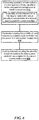
- FIG. 6 is a diagram illustrating an example method of interconnecting a plurality of sub-modules of a first or second type to a battery pack controller in a battery pack.
- the example method comprises connecting a plurality of sub-modules of a first type in series, parallel or both to create a high voltage power bus at block 602.
- the plurality of sub-modules of the first type can be replaced with a plurality of sub-modules of a second type to create the power bus.
- the plurality of sub-modules of the first type comprises cylindrical lithium-ion cells and the plurality of sub-modules of the second type comprises prismatic or pouch lithium-ion cells.
- the plurality of sub-modules of the first type comprises lithium-ion cells made by a first supplier and the plurality of sub-modules of the second type comprises lithium-ion cells made by a second supplier.
- the plurality of sub-modules of the first type comprises lithium-ion cells based on a first technology and the plurality of sub-modules of the second type comprises lithium-ion cells based on a second technology.
Landscapes
- Engineering & Computer Science (AREA)
- Chemical & Material Sciences (AREA)
- Manufacturing & Machinery (AREA)
- Chemical Kinetics & Catalysis (AREA)
- Electrochemistry (AREA)
- General Chemical & Material Sciences (AREA)
- Microelectronics & Electronic Packaging (AREA)
- Materials Engineering (AREA)
- Physics & Mathematics (AREA)
- General Physics & Mathematics (AREA)
- Battery Mounting, Suspending (AREA)
- Charge And Discharge Circuits For Batteries Or The Like (AREA)
- Secondary Cells (AREA)
Abstract
Description
- An electric battery is a device including one or more electrochemical cells that convert stored chemical energy into electrical energy. There are different types of battery technology. Lithium-ion is an example of an emerging battery cell technology that is popular in mobile devices, power tools, electric vehicles and energy storage applications. Common lithium-ion batteries use a lithium compound as one electrode material and carbon as another electrode material. In a discharge process of a typical lithium-ion battery, lithium ions move from a negative electrode to a positive electrode, through an electrolyte, generating a voltage. Lithium-ion battery technology has a number of advantages including long battery life, improved energy density and wide operating temperature range. Cell suppliers typically offer batteries based on different lithium-ion cell technologies and having different form factors (i.e., shape and size).
- In accordance with some embodiments, a cell agnostic battery module comprises a chassis having compartments for receiving sub-modules of a first type and a second type. The sub-modules include lithium-ion cells and can be connected in series, parallel or series and parallel. The battery module further comprises a battery pack controller, and internal interconnects adapted for coupling the sub-modules received in the compartments to the battery pack controller. The internal interconnects, in some aspects, can include a sub-module power bus adapted for coupling a power connector on the battery pack controller with complementary power connectors on the sub-modules and a sub-module communication bus adapted for coupling at least one communication connector on the battery pack controller with complementary communication connectors on the sub-modules. In further aspects, the internal interconnects comprise low voltage power adapted for coupling with a power and ground connector on the battery pack controller with complementary power and ground connectors on the sub-modules to supply low voltage power to the sub-modules. In other aspects, the internal interconnects further comprise a digital I/O adapted for coupling a digital I/O connector on the battery pack controller with complementary digital I/O connectors on the sub-modules to receive/send a digital I/O signal. In some aspects, the battery pack controller further comprises external interconnects adapted for coupling with signal and power connectors on the battery pack controller.
- In some aspects, the sub-modules of the first type and the second type comprise lithium-ion battery cells of different form factor type. The form factor type is one of cylindrical type, pouch type or prismatic type. In other aspects, the sub-modules of the first type and the second type include sub-modules from different suppliers. In yet other aspects, the sub-modules of the first type and the second type include sub-modules using different cell technologies.
- In some aspects, the chassis further comprises one or more fans to provide airflow through an interior of the chassis. In further aspects, the chassis can comprise a metal bezel attached to a front end. The metal bezel may have a ventilation pattern to provide airflow through the interior of the chassis.
- In accordance with some embodiments, a battery module comprises a chassis having at least two compartments configured to receive at least two sub-modules. Each sub-module may comprise lithium-ion cells of cylindrical type, pouch type or prismatic type. The at least two sub-modules may be connected in series or parallel to provide a target pack voltage and a target energy density. The battery module includes a battery module controller disposed in the chassis. The battery module controller may be electrically coupled with the at least two sub-modules via internal interconnects comprising a bi-directional power bus, a bi-directional communication bus, a sub-module power and ground line and a digital input/output line.
- In some aspects, the battery module may comprise a backplane connector for signal and power connections. The chassis of the battery module may also comprise one or more fans to provide airflow through an interior of the chassis. In some aspects, a metal bezel may be attached to a front end of the chassis. The metal bezel may comprise a ventilation pattern to provide airflow through an interior of the chassis. Contactors adapted to control connection of a DC voltage output to a DC high voltage power bus of an energy storage system may be disposed in the chassis in some aspects.
- In accordance with some embodiments, a plurality of sub-modules of a first or second type may be interconnected to a battery pack controller in a battery pack by connecting a plurality of sub-modules of a first type in series, parallel or both to create a high voltage power bus. The plurality of sub-modules of the first type may be replaceable with a plurality of sub-modules of a second type to create the power bus. The example method may further comprise electrically coupling the plurality of sub-modules of the first or second type to a battery pack controller via a bi-directional high voltage power bus and a power supply bus. In some aspects, the example method may further comprise communicatively coupling the plurality of sub-modules to the battery pack controller via a sub-module communication bus and one or more digital I/O connections.
- In some aspects, the plurality of sub-modules of the first type comprises lithium-ion cells of cylindrical form factor and the plurality of sub-modules of the second type comprises lithium-ion cells of prismatic or pouch form factor. In other aspects, voltage on the high voltage power bus is 300V or at least 48V. The voltage on the high voltage power bus may be electrically coupling to a load. In some aspects, the battery pack controller may be coupled to an external communication bus separate from the sub-module or internal communication bus.
- In accordance with some embodiments, a sub-module configured to be connected with one or more other sub-modules to create a battery pack with a targeted pack voltage and energy density may comprise lithium ion cell sub-modules comprising lithium ion cells of the same type, components for executing cell monitoring and balancing functions, a sub-module interface adapted for interconnecting with a battery pack controller including a power terminal for coupling with a bi-directional DC power bus, a power terminal for coupling with a power supply bus, one or more digital I/O terminals for coupling one or more digital I/O links and a communication terminal for coupling with a communication bus.
-
-
FIG. 1 is a diagram illustrating example components of a battery pack in accordance with some embodiments. -
FIG. 2 is a diagram illustrating interconnection of sub-modules to a battery pack controller in accordance with some embodiments. -
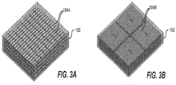
FIGs. 3A and 3B are diagrams illustrating a sub-module comprising cylindrical cells and pouch cells respectively. -
FIG. 4 is a diagram illustrating a 3D exploded view of a battery pack in accordance with some embodiments. -
FIG. 5 is a diagram illustrating a battery pack including a group of sub-modules in accordance with some embodiments. -
FIG. 6 is a diagram illustrating an example method of interconnecting a plurality of sub-modules of a first or second type to a battery pack controller in a battery pack. - Lithium-ion battery packs or modules can be made using any of a number of cell technologies such as, but not limited to: lithium-ion Iron Phosphate (LFP), lithium-ion Nickel Manganese Cobalt Oxide (NMC) and lithium-ion Nickel Cobalt Oxide (NCA). The lithium-ion cells are available in different form factors (e.g., cylindrical, prismatic, pouch). One of the disadvantages of existing lithium-ion battery packs is that they are designed for a specific cell technology and form factor offered by a cell manufacturer (e.g., Sony). This level of customization means that it is not possible to switch from cells made by one cell manufacturer to another without changing the battery pack design. Consequently, the battery pack would need to be redesigned to accommodate the new cells without affecting the output voltage, energy density, and/or other characteristics such as performance and reliability. Once the battery pack is redesigned, it becomes necessary to bring the battery pack under regulatory compliance (e.g., Underwriters Laboratories (UL) certification). Certification for lithium-ion battery packs having voltages greater than 60V is already a challenging process, but with the certification standards generally varying from country to country, re-certification can require significant time and effort. Thus, changing the cell technology/form factor/supplier for a battery pack can involve not just a redesign of the battery pack but also recertification, all of which can be time consuming and costly. Because of these inefficiencies, battery pack manufacturers are often stuck with the same cell supplier which can impact their ability to produce battery packs at a competitive cost or resolve cell quality issues.
- The battery pack described in the present disclosure has a sub-module based architecture, which helps make the battery pack effectively "cell agnostic," thereby addressing the challenges of existing battery packs. The cell agnostic battery pack comprises one or more sub-modules connected to a battery pack controller via an internal interconnect interface. The sub-modules comprise lithium-ion cells of any cell technology and type (e.g., cylindrical, pouch, prismatic), and as such can be supplied by any cell supplier. The sub-modules can be interconnected in series, parallel or both series and parallel to create a power bus (e.g., 150V, 300V). Moreover, the sub-modules can be individually certified (e.g., by cell suppliers that manufacture the sub-modules), which reduces the burden on the battery pack manufacturer to recertify the battery pack when switching from a sub-module made by one cell supplier to another cell supplier.
- These and various other embodiments, aspects and advantages of the cell agnostic battery pack will now be described in detail.
-
FIG. 1 is a block diagram illustrating example components of a cellagnostic battery pack 100 in accordance with some embodiments. Thebattery pack 100 comprises at least one sub-module 102. In some aspects, thebattery pack 100 can comprisemultiple sub-modules 102 connected in series, parallel or series and parallel to provide a target pack voltage and energy density. By way of example, a target pack voltage and energy density of an example battery pack having multiple modules can be 300V and 7kWh. - The sub-module 102 comprises cells and cell assembles. As depicted in
FIG. 1 , the sub-module 102 comprises one or more lithium-ion cell sub-modules 104. The lithium-ion cell sub-modules 104 in turn comprise lithium-ion cells of a specific form factor (e.g., cylindrical, pouch, prismatic) and cell technology.FIG. 3A depicts an example arrangement of 8cylindrical cell sub-modules 104A disposed in a sub-module 102. Similarly,FIG. 3B depicts an example arrangement of 4 pouch cell sub-modules 104B disposed in a sub-module 102. - In some aspects, the sub-module 102 further comprises control and monitoring electronics for safety and/or operational efficiency. By way of example, the sub-module 102 can include a cell voltage monitoring and balancing
circuit 106 and celltemperature monitoring circuit 108 including temperature and/or other sensors. The cell voltage monitoring and balancingcircuit 106 can monitor cell voltage and temperature (via cell temperature monitoring circuit 108) as these are generally indicative of impending faults or failure, and balance cell and string voltage based on external command (e.g., from battery pack controller 114). - The sub-module 102 also comprises a
power supply module 110 and acommunication module 112. Thepower supply module 110 supplies power andground 140 to the control and monitoring electronics. Thecommunication module 112 supports receiving and sending of data over a communication bus 144. In some aspects, the communication bus 144 can be a Controller Area Network (CAN) bus. The sub-module 102, in some aspects, includes one or more digital I/O pins through which digital I/O link 142 can be communicated. By way of example, emergency fault (e.g., cell over voltage) can be reported through a digital I/O link 142. - The
battery pack 100 also comprises abattery pack controller 114. Embodiments of thebattery pack controller 114 can include various modules for controlling and managing thebattery pack 100. By way of example, thebattery pack controller 114 can include modules forpower supply 116, a packdisconnect contactor control 118, monitoring 120, fault andprotection 122, state machine andalgorithms 124,data storage 126, light emittingdiode control 128 andcommunication 130. - The
monitoring module 120 can monitor pack voltage, current, temperature, and/or other operating characteristics of the sub-modules 102. The fault andprotection module 122 can protect thebattery pack 100 against over voltage, under voltage, over temperature, ground fault, and/or other fault conditions using redundant analog measurement (e.g., from the monitoring module 120). The packdisconnect contactor control 118 can control the contactors to connect or disconnect thebattery pack 100 from a load (e.g., high voltage power bus). The state machine andalgorithms 124 can include logic for battery pack state machine, auto addressing, firmware upgrade, warranty model, SOC, SOH and EOL, and the like. Thedata storage module 126 can include non-volatile (NV) storage for data logging, firmware upgrade, factory data, and the like. - The light emitting
diode control 128 can include logic for controlling an LED light pipe. In some aspects, the LED light pipe can provide an indication of the health of the sub-modules. For example, the LED light pipe can turn red from green to indicate failure of one or more sub-modules. - The
communication module 130 can support communication with the sub-modules 102 over an internal communication bus 144. Thecommunication module 130 can also support communication with external modules (e.g., other battery packs, a battery management system) over a separate and independent external communication bus. - The
battery pack controller 114 and the sub-modules 102 are electrically and communicatively connected or coupled via internal interconnects. In some embodiments, the internal interconnects coupling thebattery pack controller 114 and the sub-modules 102 include a power bus 138, sub-module power andground line 140, one or more digital I/O line(s)142 and a communication bus 144. The power bus 138 interconnects a power connector on thebattery pack controller 114 with complementary power connectors on the sub-modules 102. The power bus 138 is created by combining the sub-modules output voltages in series, parallel or series and parallel. By way of example,FIG. 2 depicts sub-modules 1-3 connected in series to create a power bus 138 that is coupled to thebattery pack controller 114. - The sub-module power and
ground line 140 interconnects a power connector on thebattery pack controller 114 to complementary power connectors on the sub-modules 102 to supply low voltage power (e.g., +12V) to the sub-modules (e.g., for operating the monitoring and balancing electronics). The one or more digital I/O lines 142 interconnect one or more digital I/O pins/connectors on thebattery pack controller 114 to complementary digital I/O pins/connectors on the sub-modules 102. The digital I/O line 142 may be utilized by thesub-modules 102 for reporting emergency fault (e.g., cell over voltage, cell temperature exceeding a threshold, etc.) to thebattery pack controller 114 in some aspects. In some aspects, thepack controller 114 can utilize the digital I/O lines 142 to send the sub-modules requests and/or responses. For example, thepack controller 114 can send charge voltage threshold, commands (e.g., go into sleep state), or the like to the sub-modules via the digital I/O lines 142. The internal communication bus 144 interconnects a communication connector on thebattery pack controller 114 to complementary communication connectors on the sub-modules to communicate data. Examples of such data can include temperate, voltage, current, cell health/status, other operating characteristics and/or data from the monitoring and balancing of the sub-modules 102. Thebattery pack controller 114 can, in some aspects, send commands or requests to the sub-modules 102 in response to reported faults or other conditions (e.g., command to balance cell and string voltage) over the internal communication bus. Referring toFIG. 2 , the communication bus 144 as depicted can be a bi-directional daisy chain bus. - The
battery pack controller 114 comprises external interconnects including a power bus 138, achassis ground 146 and signal in and signal out lines which are coupled to power connector 132,signal connector 134 andsignal connector 136 respectively. Via the power bus and signal in/out lines, thebattery pack 100 may be coupled with one or more other battery packs, external modules and/or load. -
FIG. 4 depicts a cellagnostic battery pack 100 in accordance with some embodiments. Thebattery pack 100 comprises achassis 422 having compartments for receivingsub-modules 102. For clarity, the sub-modules 102 are not shown. Thechassis 422 has a number of compartments to receive a number ofsub-modules 102. The sub-modules can be secured inside the chassis viasub-module brackets signal connector 134 and OUT signal connector 136) on thebattery pack controller 114 can be metal connectors disposed on the outside edge of thebattery pack 100. Thebattery pack 100 includes one ormore contactors 426 for selectively electrically coupling the battery pack output to that of other battery packs or to an electrical load external to the battery pack. The one ormore contactors 426 can be actuated in response to signal from the pack disconnectcontactor control module 118. - The
chassis 422 includes a number of printed circuit board assemblies for thebattery pack controller 114,fuse circuit 434, light pipe andLED circuit 432. Afan assembly 436 may also be disposed in thechassis 422 to induce air flow through the interior of thechassis 422. Afront bezel 438 can be secured on to the front face of thechassis 422. In some embodiments, thefront bezel 438 can have a ventilation pattern to promote air flow through an interior of thechassis 422. A removabletop cover 440 affixes to thechassis 422 to form thebattery pack 100 as depicted. An example of abattery pack 100 including ninesub-modules 102 inserted into compartments in the chassis is depicted inFIG. 5 . In this example embodiment, the nine sub-modules 102 are connected via bus bars in series and parallel configuration to create a target pack voltage and energy density. The sub-modules 102 are coupled with thebattery pack controller 114 the PCB via the internal interconnects described in reference toFIGs. 1 and2 . -
FIG. 6 is a diagram illustrating an example method of interconnecting a plurality of sub-modules of a first or second type to a battery pack controller in a battery pack. The example method comprises connecting a plurality of sub-modules of a first type in series, parallel or both to create a high voltage power bus at block 602. At block 604, the plurality of sub-modules of the first type can be replaced with a plurality of sub-modules of a second type to create the power bus. In some aspects, the plurality of sub-modules of the first type comprises cylindrical lithium-ion cells and the plurality of sub-modules of the second type comprises prismatic or pouch lithium-ion cells. In other aspects, the plurality of sub-modules of the first type comprises lithium-ion cells made by a first supplier and the plurality of sub-modules of the second type comprises lithium-ion cells made by a second supplier. In yet other aspects, the plurality of sub-modules of the first type comprises lithium-ion cells based on a first technology and the plurality of sub-modules of the second type comprises lithium-ion cells based on a second technology. - The example method further comprises electrically coupling the plurality of sub-modules of the first or second type to a battery pack controller via a bi-directional high voltage power bus and a power supply at block 606. At block 608, the example method comprises communicatively coupling the plurality of sub-modules to the battery pack controller via a sub-module communication bus and one or more digital I/Os.
- Unless the context clearly requires otherwise, throughout the description and the claims, the words "comprise," "comprising," and the like are to be construed in an inclusive sense, as opposed to an exclusive or exhaustive sense; that is to say, in the sense of "including, but not limited to." As used herein, the terms "connected," "coupled," or any variant thereof, means any connection or coupling, either direct or indirect, between two or more elements; the coupling of connection between the elements can be physical, logical, or a combination thereof. Additionally, the words "herein," "above," "below," and words of similar import, when used in this application, shall refer to this application as a whole and not to any particular portions of this application. Where the context permits, words in the above Detailed Description using the singular or plural number may also include the plural or singular number respectively. The word "or," in reference to a list of two or more items, covers all of the following interpretations of the word: any of the items in the list, all of the items in the list, and any combination of the items in the list.
- The above detailed description of embodiments of the disclosure is not intended to be exhaustive or to limit the teachings to the precise form disclosed above. While specific embodiments of, and examples for, the disclosure are described above for illustrative purposes, various equivalent modifications are possible within the scope of the disclosure, as those skilled in the relevant art will recognize. For example, while processes or blocks are presented in a given order, alternative embodiments may perform routines having steps, or employ systems having blocks in a different order, and some processes or blocks may be deleted, moved, added, subdivided, combined, and/or modified to provide alternative or subcombinations. Each of these processes or blocks may be implemented in a variety of different ways. Also, while processes or blocks are at times shown as being performed in series, these processes or blocks may instead be performed in parallel, or may be performed at different times. Further any specific numbers noted herein are only examples: alternative implementations may employ differing values or ranges.
- The teachings of the disclosure provided herein can be applied to other systems, not necessarily the system described above. The elements and acts of the various embodiments described above can be combined to provide further embodiments.
- Any patents and applications and other references noted above, including any that may be listed in accompanying filing papers, are incorporated herein by reference. Aspects of the disclosure can be modified, if necessary, to employ the systems, functions, and concepts of the various references described above to provide yet further embodiments of the disclosure.
- These and other changes can be made to the disclosure in light of the above Detailed Description. While the above description describes certain embodiments of the disclosure, and describes the best mode contemplated, no matter how detailed the above appears in text, the teachings can be practiced in many ways. Details of the system may vary considerably in its implementation details, while still being encompassed by the subject matter disclosed herein. As noted above, particular terminology used when describing certain features or aspects of the disclosure should not be taken to imply that the terminology is being redefined herein to be restricted to any specific characteristics, features, or aspects of the disclosure with which that terminology is associated. In general, the terms used in the following claims should not be construed to limit the disclosure to the specific embodiments disclosed in the specification, unless the above Detailed Description section explicitly defines such terms. Accordingly, the actual scope of the disclosure encompasses not only the disclosed embodiments, but also all equivalent ways of practicing or implementing the disclosure under the claims.
- From the foregoing, it will be appreciated that specific embodiments have been described herein for purposes of illustration, but that various modifications may be made without deviating from the spirit and scope of the embodiments. Accordingly, the embodiments are not limited except as by the appended claims.
Claims (14)
- A cell agnostic battery module comprising:a chassis comprising:compartments for receiving sub-modules of a first type and a second type, the sub-modules including lithium-ion cells and being connectable in series, parallel or series and parallel; anda battery pack controller; andinternal interconnects adapted for coupling the sub-modules received in the compartments to the battery pack controller, the internal interconnects comprising:a sub-module power bus adapted for coupling a power connector on the battery pack controller with complementary power connectors on the sub-modules; anda sub-module communication bus adapted for coupling at least one communication connector on the battery pack controller with complementary communication connectors on the sub-modules.
- The cell agnostic battery module of claim 1, wherein the battery pack controller further comprises external interconnects adapted for coupling with signal and power connectors on the battery pack controller.
- The cell agnostic battery module of claim 1, wherein the internal interconnects further comprise low voltage power adapted for coupling with a power and ground connector on the battery pack controller with complementary power and ground connectors on the sub-modules to supply low voltage power to the sub-modules.
- The cell agnostic battery module of claim 3, wherein the internal interconnects further comprise a digital I/O adapted for coupling a digital I/O connector on the battery pack controller with complementary digital I/O connectors on the sub-modules to receive/send a digital I/O signal.
- The cell agnostic battery module of claim 1, wherein the sub-modules of the first type and the second type comprise lithium-ion battery cells of different form factor type.
- The cell agnostic battery module of claim 5, wherein the form factor type is one of cylindrical type, pouch type or prismatic type.
- The cell agnostic battery module of claim 1, wherein the sub-modules of the first type and the second type include sub-modules from different suppliers.
- The cell agnostic battery module of claim 1, wherein the sub-modules of the first type and the second type include sub-modules using different cell technologies.
- The cell agnostic battery module of claim 1, wherein the chassis further comprises one or more fans to provide airflow through an interior of the chassis and a metal bezel attached to a front end of the chassis, the metal bezel comprising a ventilation pattern to provide airflow through the interior of the chassis.
- A method of interconnecting a plurality of sub-modules of a first or second type to a battery pack controller in a battery pack, comprising:connecting a plurality of sub-modules of a first type in series, parallel or both to create a high voltage power bus, wherein the plurality of sub-modules of the first type are replaceable with a plurality of sub-modules of a second type to create the power bus;electrically coupling the plurality of sub-modules of the first or second type to a battery pack controller via:a bi-directional high voltage power bus; anda power supply bus;communicatively coupling the plurality of sub-modules to the battery pack controller via:a sub-module communication bus; andone or more digital I/O connections.
- The method of claim 10, wherein the plurality of sub-modules of the first type comprises lithium-ion cells of cylindrical form factor and the plurality of sub-modules of the second type comprises lithium-ion cells of prismatic or pouch form factor.
- The method of claim 10, wherein voltage on the high voltage power bus is 300V.
- The method of claim 10, further comprising electrically coupling voltage on the high voltage power bus to a load.
- The method of claim 10, further comprising coupling the battery pack controller to an external communication bus separate from the sub-module communication bus.
Applications Claiming Priority (1)
| Application Number | Priority Date | Filing Date | Title |
|---|---|---|---|
| US201762444649P | 2017-01-10 | 2017-01-10 |
Publications (3)
| Publication Number | Publication Date |
|---|---|
| EP3346541A1 true EP3346541A1 (en) | 2018-07-11 |
| EP3346541B1 EP3346541B1 (en) | 2025-03-05 |
| EP3346541C0 EP3346541C0 (en) | 2025-03-05 |
Family
ID=60953728
Family Applications (1)
| Application Number | Title | Priority Date | Filing Date |
|---|---|---|---|
| EP18150847.4A Active EP3346541B1 (en) | 2017-01-10 | 2018-01-09 | Cell agnostic battery pack |
Country Status (2)
| Country | Link |
|---|---|
| US (1) | US10964979B2 (en) |
| EP (1) | EP3346541B1 (en) |
Families Citing this family (5)
| Publication number | Priority date | Publication date | Assignee | Title |
|---|---|---|---|---|
| CN109004300A (en) * | 2018-08-09 | 2018-12-14 | 肇庆市高新区甜慕新能源技术有限公司 | A kind of battery module having communication bus |
| CN114374006A (en) * | 2021-12-31 | 2022-04-19 | 欣旺达电动汽车电池有限公司 | Battery Management Systems and Electric Vehicles |
| US12542438B2 (en) * | 2022-04-08 | 2026-02-03 | Enphase Energy, Inc. | Integrated PCBA design with fast connection-disconnection capabilities for cell to system design |
| US12362963B2 (en) * | 2022-08-02 | 2025-07-15 | Stmicroelectronics Application Gmbh | Electronic device, corresponding bus communication system and method of configuring a bus communication system |
| WO2024049630A1 (en) * | 2022-09-02 | 2024-03-07 | Enphase Energy, Inc. | Fast engaging-disengaging connectors for cell-to-system battery design |
Citations (2)
| Publication number | Priority date | Publication date | Assignee | Title |
|---|---|---|---|---|
| WO2012125616A1 (en) * | 2011-03-17 | 2012-09-20 | Streamlight, Inc. | Light having a compartment and/or circuit accommodating batteries of different types, sizes and/or shapes |
| US20160093848A1 (en) * | 2014-09-30 | 2016-03-31 | Johnson Controls Technology Company | Modular approach for advanced battery modules having different electrical characteristics |
Family Cites Families (3)
| Publication number | Priority date | Publication date | Assignee | Title |
|---|---|---|---|---|
| KR101094002B1 (en) | 2009-12-16 | 2011-12-15 | 삼성에스디아이 주식회사 | Power converter |
| US9444275B2 (en) | 2011-08-31 | 2016-09-13 | North Carolina State University | Intelligent integrated battery module |
| US9780591B2 (en) | 2015-04-03 | 2017-10-03 | Schneider Electric It Corporation | Adaptive battery pack |
-
2018
- 2018-01-09 US US15/865,572 patent/US10964979B2/en active Active
- 2018-01-09 EP EP18150847.4A patent/EP3346541B1/en active Active
Patent Citations (2)
| Publication number | Priority date | Publication date | Assignee | Title |
|---|---|---|---|---|
| WO2012125616A1 (en) * | 2011-03-17 | 2012-09-20 | Streamlight, Inc. | Light having a compartment and/or circuit accommodating batteries of different types, sizes and/or shapes |
| US20160093848A1 (en) * | 2014-09-30 | 2016-03-31 | Johnson Controls Technology Company | Modular approach for advanced battery modules having different electrical characteristics |
Also Published As
| Publication number | Publication date |
|---|---|
| US20180198178A1 (en) | 2018-07-12 |
| US10964979B2 (en) | 2021-03-30 |
| EP3346541B1 (en) | 2025-03-05 |
| EP3346541C0 (en) | 2025-03-05 |
Similar Documents
| Publication | Publication Date | Title |
|---|---|---|
| EP3346541B1 (en) | Cell agnostic battery pack | |
| CN102754301B (en) | Power supply device | |
| JP4929389B2 (en) | Battery system | |
| CN103580107B (en) | Battery management system, battery module, battery system and motor vehicle | |
| US9837811B2 (en) | Power source apparatus formed by combining a plurality of modules | |
| EP2608347A2 (en) | Electric energy storage system and method of maintaining the same | |
| US10326288B2 (en) | Method and device for the voltage-controlled self-deactivation of electronic components or battery cells | |
| JP6694548B2 (en) | Fuse diagnostic device and method using voltage distribution | |
| JP2013097926A (en) | Storage battery unit | |
| CN104054213B (en) | For the cell apparatus of motor vehicle | |
| US11469470B2 (en) | Battery module with series connected cells, internal relays and internal battery management system | |
| US11575270B2 (en) | Battery module with series connected cells, internal relays and internal battery management system | |
| JP2010537362A (en) | Secondary battery pack or primary battery pack | |
| DE102014220033A1 (en) | An electrochemical energy storage device for a storage unit of an electrochemical energy storage system, a method for controlling a flow of electrical energy in an electrochemical energy storage system, and an electrochemical energy storage system | |
| CN110832334B (en) | Fault diagnosis device | |
| JP2014041747A (en) | Accumulator battery device, method of managing the same, and accumulator battery system | |
| EP3014726B1 (en) | Energy storage system | |
| CN107546794B (en) | Controller, configuration device, method, assembly and advancing device for operating a module of electrical storage cells | |
| US11380942B2 (en) | High voltage battery module with series connected cells and internal relays | |
| KR20180087159A (en) | Battery modules having a plurality of submodules | |
| US12046930B2 (en) | Battery system | |
| CN217009386U (en) | Energy storage battery cluster | |
| WO2024226162A1 (en) | Configurable resistor bank for battery manager | |
| CN214253003U (en) | Programmable controller integrated test system | |
| KR20160128758A (en) | Independent power source with wireless communication |
Legal Events
| Date | Code | Title | Description |
|---|---|---|---|
| PUAI | Public reference made under article 153(3) epc to a published international application that has entered the european phase |
Free format text: ORIGINAL CODE: 0009012 |
|
| STAA | Information on the status of an ep patent application or granted ep patent |
Free format text: STATUS: REQUEST FOR EXAMINATION WAS MADE |
|
| 17P | Request for examination filed |
Effective date: 20180109 |
|
| AK | Designated contracting states |
Kind code of ref document: A1 Designated state(s): AL AT BE BG CH CY CZ DE DK EE ES FI FR GB GR HR HU IE IS IT LI LT LU LV MC MK MT NL NO PL PT RO RS SE SI SK SM TR |
|
| AX | Request for extension of the european patent |
Extension state: BA ME |
|
| RBV | Designated contracting states (corrected) |
Designated state(s): AL AT BE BG CH CY CZ DE DK EE ES FI FR GB GR HR HU IE IS IT LI LT LU LV MC MK MT NL NO PL PT RO RS SE SI SK SM TR |
|
| GRAP | Despatch of communication of intention to grant a patent |
Free format text: ORIGINAL CODE: EPIDOSNIGR1 |
|
| STAA | Information on the status of an ep patent application or granted ep patent |
Free format text: STATUS: GRANT OF PATENT IS INTENDED |
|
| INTG | Intention to grant announced |
Effective date: 20240925 |
|
| GRAS | Grant fee paid |
Free format text: ORIGINAL CODE: EPIDOSNIGR3 |
|
| GRAA | (expected) grant |
Free format text: ORIGINAL CODE: 0009210 |
|
| STAA | Information on the status of an ep patent application or granted ep patent |
Free format text: STATUS: THE PATENT HAS BEEN GRANTED |
|
| RAP3 | Party data changed (applicant data changed or rights of an application transferred) |
Owner name: SCHNEIDER ELECTRIC IT CORPORATION |
|
| AK | Designated contracting states |
Kind code of ref document: B1 Designated state(s): AL AT BE BG CH CY CZ DE DK EE ES FI FR GB GR HR HU IE IS IT LI LT LU LV MC MK MT NL NO PL PT RO RS SE SI SK SM TR |
|
| REG | Reference to a national code |
Ref country code: GB Ref legal event code: FG4D |
|
| REG | Reference to a national code |
Ref country code: CH Ref legal event code: EP |
|
| REG | Reference to a national code |
Ref country code: DE Ref legal event code: R096 Ref document number: 602018079754 Country of ref document: DE |
|
| REG | Reference to a national code |
Ref country code: IE Ref legal event code: FG4D |
|
| U01 | Request for unitary effect filed |
Effective date: 20250324 |
|
| U07 | Unitary effect registered |
Designated state(s): AT BE BG DE DK EE FI FR IT LT LU LV MT NL PT RO SE SI Effective date: 20250328 |
|
| PG25 | Lapsed in a contracting state [announced via postgrant information from national office to epo] |
Ref country code: RS Free format text: LAPSE BECAUSE OF FAILURE TO SUBMIT A TRANSLATION OF THE DESCRIPTION OR TO PAY THE FEE WITHIN THE PRESCRIBED TIME-LIMIT Effective date: 20250605 |
|
| PG25 | Lapsed in a contracting state [announced via postgrant information from national office to epo] |
Ref country code: ES Free format text: LAPSE BECAUSE OF FAILURE TO SUBMIT A TRANSLATION OF THE DESCRIPTION OR TO PAY THE FEE WITHIN THE PRESCRIBED TIME-LIMIT Effective date: 20250305 |
|
| PG25 | Lapsed in a contracting state [announced via postgrant information from national office to epo] |
Ref country code: NO Free format text: LAPSE BECAUSE OF FAILURE TO SUBMIT A TRANSLATION OF THE DESCRIPTION OR TO PAY THE FEE WITHIN THE PRESCRIBED TIME-LIMIT Effective date: 20250605 |
|
| PG25 | Lapsed in a contracting state [announced via postgrant information from national office to epo] |
Ref country code: HR Free format text: LAPSE BECAUSE OF FAILURE TO SUBMIT A TRANSLATION OF THE DESCRIPTION OR TO PAY THE FEE WITHIN THE PRESCRIBED TIME-LIMIT Effective date: 20250305 |
|
| PG25 | Lapsed in a contracting state [announced via postgrant information from national office to epo] |
Ref country code: GR Free format text: LAPSE BECAUSE OF FAILURE TO SUBMIT A TRANSLATION OF THE DESCRIPTION OR TO PAY THE FEE WITHIN THE PRESCRIBED TIME-LIMIT Effective date: 20250606 |
|
| PG25 | Lapsed in a contracting state [announced via postgrant information from national office to epo] |
Ref country code: SM Free format text: LAPSE BECAUSE OF FAILURE TO SUBMIT A TRANSLATION OF THE DESCRIPTION OR TO PAY THE FEE WITHIN THE PRESCRIBED TIME-LIMIT Effective date: 20250305 |
|
| PG25 | Lapsed in a contracting state [announced via postgrant information from national office to epo] |
Ref country code: PL Free format text: LAPSE BECAUSE OF FAILURE TO SUBMIT A TRANSLATION OF THE DESCRIPTION OR TO PAY THE FEE WITHIN THE PRESCRIBED TIME-LIMIT Effective date: 20250305 |
|
| PG25 | Lapsed in a contracting state [announced via postgrant information from national office to epo] |
Ref country code: CZ Free format text: LAPSE BECAUSE OF FAILURE TO SUBMIT A TRANSLATION OF THE DESCRIPTION OR TO PAY THE FEE WITHIN THE PRESCRIBED TIME-LIMIT Effective date: 20250305 |
|
| PG25 | Lapsed in a contracting state [announced via postgrant information from national office to epo] |
Ref country code: SK Free format text: LAPSE BECAUSE OF FAILURE TO SUBMIT A TRANSLATION OF THE DESCRIPTION OR TO PAY THE FEE WITHIN THE PRESCRIBED TIME-LIMIT Effective date: 20250305 |
|
| PG25 | Lapsed in a contracting state [announced via postgrant information from national office to epo] |
Ref country code: IS Free format text: LAPSE BECAUSE OF FAILURE TO SUBMIT A TRANSLATION OF THE DESCRIPTION OR TO PAY THE FEE WITHIN THE PRESCRIBED TIME-LIMIT Effective date: 20250705 |
|
| PLBE | No opposition filed within time limit |
Free format text: ORIGINAL CODE: 0009261 |
|
| STAA | Information on the status of an ep patent application or granted ep patent |
Free format text: STATUS: NO OPPOSITION FILED WITHIN TIME LIMIT |
|
| REG | Reference to a national code |
Ref country code: CH Ref legal event code: L10 Free format text: ST27 STATUS EVENT CODE: U-0-0-L10-L00 (AS PROVIDED BY THE NATIONAL OFFICE) Effective date: 20260114 |
|
| 26N | No opposition filed |
Effective date: 20251208 |
|
| U20 | Renewal fee for the european patent with unitary effect paid |
Year of fee payment: 9 Effective date: 20260126 |
|
| PGFP | Annual fee paid to national office [announced via postgrant information from national office to epo] |
Ref country code: GB Payment date: 20260126 Year of fee payment: 9 |