EP3346217A1 - Refrigeration device - Google Patents
Refrigeration device Download PDFInfo
- Publication number
- EP3346217A1 EP3346217A1 EP16899025.7A EP16899025A EP3346217A1 EP 3346217 A1 EP3346217 A1 EP 3346217A1 EP 16899025 A EP16899025 A EP 16899025A EP 3346217 A1 EP3346217 A1 EP 3346217A1
- Authority
- EP
- European Patent Office
- Prior art keywords
- door body
- slide rail
- cabinet
- snap
- refrigeration apparatus
- Prior art date
- Legal status (The legal status is an assumption and is not a legal conclusion. Google has not performed a legal analysis and makes no representation as to the accuracy of the status listed.)
- Granted
Links
Images




Classifications
-
- A—HUMAN NECESSITIES
- A47—FURNITURE; DOMESTIC ARTICLES OR APPLIANCES; COFFEE MILLS; SPICE MILLS; SUCTION CLEANERS IN GENERAL
- A47B—TABLES; DESKS; OFFICE FURNITURE; CABINETS; DRAWERS; GENERAL DETAILS OF FURNITURE
- A47B88/00—Drawers for tables, cabinets or like furniture; Guides for drawers
- A47B88/40—Sliding drawers; Slides or guides therefor
-
- F—MECHANICAL ENGINEERING; LIGHTING; HEATING; WEAPONS; BLASTING
- F25—REFRIGERATION OR COOLING; COMBINED HEATING AND REFRIGERATION SYSTEMS; HEAT PUMP SYSTEMS; MANUFACTURE OR STORAGE OF ICE; LIQUEFACTION SOLIDIFICATION OF GASES
- F25D—REFRIGERATORS; COLD ROOMS; ICE-BOXES; COOLING OR FREEZING APPARATUS NOT OTHERWISE PROVIDED FOR
- F25D23/00—General constructional features
- F25D23/02—Doors; Covers
-
- F—MECHANICAL ENGINEERING; LIGHTING; HEATING; WEAPONS; BLASTING
- F25—REFRIGERATION OR COOLING; COMBINED HEATING AND REFRIGERATION SYSTEMS; HEAT PUMP SYSTEMS; MANUFACTURE OR STORAGE OF ICE; LIQUEFACTION SOLIDIFICATION OF GASES
- F25D—REFRIGERATORS; COLD ROOMS; ICE-BOXES; COOLING OR FREEZING APPARATUS NOT OTHERWISE PROVIDED FOR
- F25D23/00—General constructional features
- F25D23/02—Doors; Covers
- F25D23/028—Details
-
- F—MECHANICAL ENGINEERING; LIGHTING; HEATING; WEAPONS; BLASTING
- F25—REFRIGERATION OR COOLING; COMBINED HEATING AND REFRIGERATION SYSTEMS; HEAT PUMP SYSTEMS; MANUFACTURE OR STORAGE OF ICE; LIQUEFACTION SOLIDIFICATION OF GASES
- F25D—REFRIGERATORS; COLD ROOMS; ICE-BOXES; COOLING OR FREEZING APPARATUS NOT OTHERWISE PROVIDED FOR
- F25D23/00—General constructional features
- F25D23/10—Arrangements for mounting in particular locations, e.g. for built-in type, for corner type
-
- F—MECHANICAL ENGINEERING; LIGHTING; HEATING; WEAPONS; BLASTING
- F25—REFRIGERATION OR COOLING; COMBINED HEATING AND REFRIGERATION SYSTEMS; HEAT PUMP SYSTEMS; MANUFACTURE OR STORAGE OF ICE; LIQUEFACTION SOLIDIFICATION OF GASES
- F25D—REFRIGERATORS; COLD ROOMS; ICE-BOXES; COOLING OR FREEZING APPARATUS NOT OTHERWISE PROVIDED FOR
- F25D25/00—Charging, supporting, and discharging the articles to be cooled
- F25D25/02—Charging, supporting, and discharging the articles to be cooled by shelves
-
- F—MECHANICAL ENGINEERING; LIGHTING; HEATING; WEAPONS; BLASTING
- F25—REFRIGERATION OR COOLING; COMBINED HEATING AND REFRIGERATION SYSTEMS; HEAT PUMP SYSTEMS; MANUFACTURE OR STORAGE OF ICE; LIQUEFACTION SOLIDIFICATION OF GASES
- F25D—REFRIGERATORS; COLD ROOMS; ICE-BOXES; COOLING OR FREEZING APPARATUS NOT OTHERWISE PROVIDED FOR
- F25D25/00—Charging, supporting, and discharging the articles to be cooled
- F25D25/02—Charging, supporting, and discharging the articles to be cooled by shelves
- F25D25/024—Slidable shelves
- F25D25/025—Drawers
-
- F—MECHANICAL ENGINEERING; LIGHTING; HEATING; WEAPONS; BLASTING
- F25—REFRIGERATION OR COOLING; COMBINED HEATING AND REFRIGERATION SYSTEMS; HEAT PUMP SYSTEMS; MANUFACTURE OR STORAGE OF ICE; LIQUEFACTION SOLIDIFICATION OF GASES
- F25D—REFRIGERATORS; COLD ROOMS; ICE-BOXES; COOLING OR FREEZING APPARATUS NOT OTHERWISE PROVIDED FOR
- F25D23/00—General constructional features
- F25D23/02—Doors; Covers
- F25D23/021—Sliding doors
-
- F—MECHANICAL ENGINEERING; LIGHTING; HEATING; WEAPONS; BLASTING
- F25—REFRIGERATION OR COOLING; COMBINED HEATING AND REFRIGERATION SYSTEMS; HEAT PUMP SYSTEMS; MANUFACTURE OR STORAGE OF ICE; LIQUEFACTION SOLIDIFICATION OF GASES
- F25D—REFRIGERATORS; COLD ROOMS; ICE-BOXES; COOLING OR FREEZING APPARATUS NOT OTHERWISE PROVIDED FOR
- F25D23/00—General constructional features
- F25D23/06—Walls
- F25D23/065—Details
- F25D23/067—Supporting elements
-
- F—MECHANICAL ENGINEERING; LIGHTING; HEATING; WEAPONS; BLASTING
- F25—REFRIGERATION OR COOLING; COMBINED HEATING AND REFRIGERATION SYSTEMS; HEAT PUMP SYSTEMS; MANUFACTURE OR STORAGE OF ICE; LIQUEFACTION SOLIDIFICATION OF GASES
- F25D—REFRIGERATORS; COLD ROOMS; ICE-BOXES; COOLING OR FREEZING APPARATUS NOT OTHERWISE PROVIDED FOR
- F25D2323/00—General constructional features not provided for in other groups of this subclass
- F25D2323/02—Details of doors or covers not otherwise covered
-
- F—MECHANICAL ENGINEERING; LIGHTING; HEATING; WEAPONS; BLASTING
- F25—REFRIGERATION OR COOLING; COMBINED HEATING AND REFRIGERATION SYSTEMS; HEAT PUMP SYSTEMS; MANUFACTURE OR STORAGE OF ICE; LIQUEFACTION SOLIDIFICATION OF GASES
- F25D—REFRIGERATORS; COLD ROOMS; ICE-BOXES; COOLING OR FREEZING APPARATUS NOT OTHERWISE PROVIDED FOR
- F25D2400/00—General features of, or devices for refrigerators, cold rooms, ice-boxes, or for cooling or freezing apparatus not covered by any other subclass
- F25D2400/22—Cleaning means for refrigerating devices
Definitions
- the present disclosure relates to a technical field of refrigeration equipment, and more particularly to a refrigeration apparatus.
- a freezer door body of a refrigeration apparatus belongs to a drawer type with a slide rail, and due to cleaning requirements, the following three conditions need to be satisfied: normal opening or closure of the door body, removal of a drawer, and removal of the entire door body.
- the slide rail of the freezer door body of the refrigeration apparatus has only one snap for fixation, and the snap is located inside the refrigeration apparatus, which is inconvenient for operation; furthermore, after the snap fails, the entire door body may be brought out easily when the door body is pulled out to remove the drawer, which causes damages; moreover, since the snap is located inside the refrigeration apparatus, operations cannot be visualized, but only depend on feelings, which is very difficult and hence has room for improvement.
- the present disclosure aims to solve at least one of the problems existing in the related art to at least some extent. Therefore, the present disclosure provides a refrigeration apparatus with high safety and usage convenience.
- the refrigeration apparatus includes: a cabinet; a door body provided to the cabinet in a drawable manner; a drawer detachably provided to the door body; a first snap assembly adapted to limit the door body at a first position where the door body is fixed to the cabinet; and a second snap assembly adapted to limit the door body at a second position where the door body is fixed to the cabinet.
- the door body passes through the first position and the second position sequentially in a process of pulling the door body out of the cabinet, the drawer is adapted to be pulled out of the door body when the first snap assembly fails, and the door body is adapted to be separated from the cabinet when the second snap assembly fails.
- two stages of snap assemblies are provided on a path of relative movement between the door body and the cabinet, three states, in which the door body is opened or closed normally, the drawer is taken out of the door body easily, and the door body is separated from the cabinet easily, can be realized when the requirement of taking or placing goods with different volumes is also satisfied. Furthermore, when the first snap assembly is damaged or fails, the second snap assembly can still function to prevent the entire door body from being brought out when the door body is pulled out to remove the drawer, thereby avoiding damage to personnel and the refrigeration apparatus.
- the refrigeration apparatus according to embodiments of the present disclosure is convenient to use and has high safety.
- the refrigeration apparatus further includes: a slide rail assembly including a slide rail support fixed to an inner wall of the cabinet; and a slide rail movably connected with the slide rail support and fixed to the door body.
- the first snap assembly includes two first snapping members that are fitted with each other, one of the two first snapping members is fixed to the slide rail support, and the other one thereof is fixed to a surface of the slide rail facing the slide rail support.
- the one of the two first snapping members is configured as a hook, while the other one thereof is configured as a protrusion.
- an end of the slide rail support facing the door body is provided with a recess recessed backwards, a bottom of the recess is provided with a protruding part that extends towards the door body and is spaced apart from two side walls of the recess, and the protruding part and one side wall of the recess form the hook.
- the hook is provided with a pressing part that is adapted to be pressed.
- the second snap assembly includes two second snapping members that are fitted with each other, one of the two second snapping members is fixed to the slide rail support, and the other one thereof is fixed to a surface of the slide rail facing the slide rail support.
- the one of the two second snapping members is configured as a snap, while the other one thereof is configured as a slot.
- the snap is provided to a side surface of the slide rail support opposite to the inner wall of the cabinet, and the snap is configured as a cantilever having an end connected with the slide rail support.
- a part of the first snap assembly adapted to be operated is provided at an edge of the cabinet adjacent to the door body, and is exposed when the door body is pulled out of the cabinet.
- refrigeration apparatus 100 cabinet 1, door body 2, drawer 3, first snap assembly 4, hook 41, pressing part 411, lightening hole 412, guide surface 413, protrusion 42, second snap assembly 5, snap 51, slot 52, slide rail assembly 6, slide rail support 61, recess 611, protruding part 612, side wall 613, slide rail 62.
- a refrigeration apparatus 100 can refrigerate and store goods that need to be stored at a low temperature.
- the refrigeration apparatus 100 can be a refrigerator, a freezer, a refrigeration cabinet and the like.
- the refrigeration apparatus 100 includes a cabinet 1, a door body 2, a drawer 3, a first snap assembly 4 and a second snap assembly 5.
- the door body 2 is provided to the cabinet 1 in a drawable manner, and the drawer 3 is detachably provided to the door body 2.
- the drawer 3 can be mounted to the door body 2; when the drawer 3 needs to be cleaned, the drawer 3 can be detached from the door body 2; when the door body 2 or an interior of the cabinet 1 needs to be repaired, the door body 2 can be drawn out of the cabinet 1, that is, the door body 2 can be separated from the cabinet 1.
- the first snap assembly 4 is configured to limit the door body 2 at a first position where the door body 2 may be fixed to the cabinet 1, that is, when the door body 2 is located in the first position, the first snap assembly 4 functions, and the door body 2 and the cabinet 1 are fixed by the first snap assembly 4.
- the second snap assembly 5 is configured to limit the door body 2 at a second position where the door body 2 may be fixed to the cabinet 1, that is, when the door body 2 is located in the second position, the second snap assembly 5 functions, and the door body 2 and the cabinet 1 are fixed by the second snap assembly 5.
- the door body 2 In a process of pulling the door body 2 out of the cabinet 1, the door body 2 passes through the first position and the second position sequentially; when the first snap assembly 4 fails, the drawer 3 is adapted to be taken out of the door body 2; when the second snap assembly 5 fails, the door body 2 is adapted to be separated from the cabinet 1.
- the door body 2 When it is only necessary to open the door body 2 to take or place the goods in the drawer 3, the door body 2 is pulled back; as illustrated in Figs. 4 and 5 , when the door body 2 is pulled to the first position, the first snap assembly 4 functions to fix the door body 2 and the cabinet 1.
- the door body 2 When the drawer 3 needs to be taken out, the door body 2 is first pulled to the first position, and then the first snap assembly 4 is operated to be disabled, i.e. the door body 2 is again movable relative to the cabinet 1; hence, the door body 2 is pulled again to a desired position, and as illustrated in Fig. 6 , the drawer 3 can be rotatably taken out, which facilitates cleaning.
- the door body 2 When the door body 2 needs to be separated from the cabinet 1, the door body 2 is first pulled to the first position illustrated in Figs. 4 and 5 ; then the first snap assembly 4 is operated to be disabled, so as to continue pulling the door body 2 until it reaches the second position illustrated in Figs. 7 and 8 ; the second snap assembly 5 is then operated to be disabled, i.e. the door body 2 is again movable relative to the cabinet 1; as illustrated in Fig. 10 , the door body 2 is pulled again to be separated from the cabinet 1, thereby facilitating repair on the door body 2 or the interior of the cabinet 1.
- first snap assembly 4 and the second snap assembly 5 both have to be disabled if it is intended to separate the door body 2 wholly from the cabinet 1.
- the door body 2 is capable of being fixed to the cabinet 1 in two positions; when the door body 2 is fixed in the first position, a distance between the door body 2 and the cabinet 1 is relatively small, which only satisfies a requirement of taking or placing part of goods, but when the door body 2 is fixed in the second position, the distance between the door body 2 and the cabinet 1 is enlarged, which can satisfies a requirement of taking or placing some goods with relatively large volume.
- a process of closing the door body 2 is opposite the above process of pulling the door body 2 out of the cabinet 1, which can be known by those skilled in the art based on the above description, and hence will not be elaborated herein.
- two stages of snap assemblies are provided on a path of relative movement between the door body 2 and the cabinet 1, three states, in which the door body 2 is opened or closed normally, the drawer 3 is taken out of the door body 2 easily, and the door body 2 is separated from the cabinet 1 easily, can be realized when the requirement of taking or placing goods with different volumes is also satisfied. Furthermore, when the first snap assembly 4 is damaged or fails, the second snap assembly 5 can still function to prevent the entire door body 2 from being brought out when the door body 2 is pulled out to remove the drawer 3, thereby avoiding damage to personnel and the refrigeration apparatus 100.
- the refrigeration apparatus according to embodiments of the present disclosure is convenient to use and has high safety.
- the refrigeration apparatus 100 includes the cabinet 1, the door body 2, the drawer 3, the first snap assembly 4, the second snap assembly 5 and a slide rail assembly 6.
- the refrigeration apparatus 100 is configured as a refrigerator, and the door body 2 is configured as a door body 2 of a freezer door of the refrigerator.
- the door body 2 is provided to the cabinet 1 in a drawable manner by means of the slide rail assembly 6.
- the drawer 3 is detachably provided to the door body 2.
- the slide rail assembly 6 includes a slide rail support 61 and a slide rail 62, and the slide rail support 61 is fixed to an inner wall of the cabinet 1.
- the slide rail 62 is fixed to the door body 2 and movably connected with the slide rail support 61, that is, the slide rail 62 is movable relative to the slide rail support 61, and the slide rail support 61 is configured to support the slide rail 62.
- the slide rail 62 can be a multistage slide rail, such that the stroke can be adjusted.
- the slide rail support 61 can be fixed to the cabinet 1 by a threaded connection, such that the installation of the slide rail assembly 61 is more convenient.
- the slide rail support 61 can be integrally formed with the cabinet 1.
- the slide rail support 61 can be a plastic part, and the slide rail 62 can be a metal slide rail. Such a material setting makes it easy to manufacture and low in production cost.
- slide rail support 61 and the slide rail 62 each include two portions symmetrically arranged in a width direction of the refrigeration apparatus 100.
- the first snap assembly 4 is configured to limit the door body 2 at the first position where the door body 2 may be fixed to the cabinet 1, and preferably, a part of the first snap assembly 4 adapted to be operated is provided at an edge of the cabinet 1 adjacent to the door body 2.
- the part of the first snap assembly 4 adapted to be operated refers to a part that can be operated to disable the first snap assembly 4 so as to make the door body 2 movable relative to the cabinet 1 and that will be exposed when the door body 2 is pulled out of the cabinet 1, that is, when the door body 2 is pulled out, the door body 2 is spaced apart from the cabinet 1, and at this time, the part for operating and disabling the first snap assembly 4 is exposed.
- the operation of the first snap assembly 4 is visualized to facilitate the operation and reduce the probability of damage to components and parts.
- the first snap assembly 4 includes two first snapping members that are fitted with each other, and one of the two first snapping members is fixed to the slide rail support 61 while the other one thereof is fixed to a surface of the slide rail 62 facing the slide rail support 61. That is, the slide rail support 61 is fixed to the inner wall of the cabinet 1, the slide rail 62 is located at an inner side of the slide rail support 61, and the two first snapping members are arranged opposite to each other and fitted with each other.
- the two first snapping members are fitted to fix the door body 2 and the cabinet 1, i.e. fixing the door body 2 at the first position; when the first snap assembly 4 fails, the two first snapping members are gradually separated to make the door body 2 movable relative to the cabinet 1.
- one of the two first snapping members is configured as a hook 41 while the other one thereof is configured as a protrusion 42.
- the protrusion 42 moves along with the slide rail 62, and the slide rail 62 is driven to move by the door body 2, such that when the protrusion 42 is snapped with the hook 41, the first snap assembly 4 functions to fix the door body 2 at the first position.
- the protrusion 42 is released from the hook 41, the first snap assembly 4 fails, and hence the door body 2 becomes movable relative to the cabinet 1.
- a bottom wall of the recess 611 is provided with a protruding part 612 extending towards the door body 2 and spaced apart from two side walls 613 of the recess 611. That is, the protruding part 612 extends forwards from the bottom wall of the recess 611, and in an up-and-down direction, the protruding part 612 is located between the two side walls 613 and spaced apart from both of the side walls 613.
- the protruding part 612 in conjunction with one of the two side walls 613 of the recess 611 forms the hook 41.
- the protruding part 612 and an upper side wall 613 of the recess 611 form the hook 41
- the protruding part 612 and a lower side wall 613 of the recess 611 define a space to provide a clearance space for movement of the hook 41.
- the protruding part 612 and the upper side wall 613 of the recess 611 define a U-shaped space with an opening facing forwards; the protruding part 612 and the lower side wall 613 of the recess 611 define a substantially Z-shaped space, including two horizontal segments and one connecting segment, in which the connecting segment is inclined forwards and downwards.
- the protruding part 612 moves more smoothly and does not interfere easily with the two side walls 613 of the recess 611.
- Such a hook 41 has a simple structure and is easy to form, and the location of the hook 41 facilitates the operation of the hook 41. That is, since the hook 41 is located at the front end of the slide rail support 61, the hook 41 is easy to see when the door body 2 is opened. Thus, the process of operating the first snap assembly 4 is visualized, the operation accuracy is high, and the first snap assembly 4 is not easily damaged.
- the hook 41 is provided with a pressing part 411 adapted to be pressed.
- the pressing part 411 is configured as a cantilever formed on the protruding part 612 and extending forwards, and an upper surface of the cantilever is an operating surface adapted to be pressed. If it is intended to operate the first snap assembly 4 so as to disable the first snap assembly 4, it is only necessary to press the operating surface, i.e. press down the pressing part 411 to separate the hook 41 from the protrusion 42.
- the protruding part 612 and the lower side wall 613 of the recess 611 can form the hook 41.
- the protruding part 612 and the upper side wall 613 of the recess 611 defines the space that provided the clearance space for the movement of the hook 41.
- the pressing part 411 is configured as a cantilever formed on the protruding part 612 and extending forwards, and a lower surface of the cantilever is an operating surface adapted to be pressed. If it is intended to operate the first snap assembly 4 so as to disable the first snap assembly 4, it is only necessary to press the operating surface, i.e. press the pressing part 411 upwards to separate the hook 41 from the protrusion 42.
- the operating surface is configured as a wavy surface to increase friction and facilitate operations of an operator.
- the operating surface can be configured as a plane with a relatively high degree of roughness.
- a middle part of the protruding part 612 is provided with a lightening hole 412, thereby ensuring the structural strength of the slide rail support 61 and reducing the weight of the slide rail support 61, in particular, reducing the weight of the hook 41, so as to further facilitate the movement and lightweight of the hook 41.
- the lightening hole 412 can be one of a triangular hole, a circular hole and a square hole.
- the most front end of the protruding part 612 is provided with a guide surface 413, and the guide surface 413 is adapted to fit with the protrusion 42 to guide the protrusion 42 into or out of the hook 41.
- the guide surface 413 is adapted to fit with the protrusion 42 to guide the protrusion 42 into or out of the hook 41.
- the guide surface 413 is formed at the most front end of an upper portion of the protruding part 612 and is inclined downwards from rear to front; in the embodiment where the protruding part 612 and the lower side wall 613 of the recess 611 form the hook 41, the guide surface 413 is formed at the most front end of a lower portion of the protruding part 612 and is inclined upwards from rear to front.
- the guide surface 413 can be a bevel surface or a curved surface. When the guide surface 413 is the bevel surface, it is easier to manufacture; when the guide surface 413 is the curved surface, the transition is smoother and the guiding performance is better.
- the second snap assembly 5 is configured to limit the door body 2 at the second position where the door body 2 is fixed to the cabinet 1.
- the second snap assembly 5 includes two second snapping members that are fitted with each other, and one of the two second snapping members is fixed to the slide rail support 61 while the other one thereof is fixed to the surface of the slide rail 62 facing the slide rail support 61. That is, the slide rail support 61 is fixed to the inner wall of the cabinet 1, the slide rail 62 is located at the inner side of the slide rail support 61, and the two second snapping members are arranged opposite to each other and fitted with each other.
- the two second snapping members are fitted to fix the door body 2 and the cabinet 1, i.e. fixing the door body 2 at the second position; when the second snap assembly 5 fails, the two second snapping members are gradually separated to make the door body 2 movable relative to the cabinet 1.
- one of the two second snapping members is configured as a snap 51, and the other one thereof is configured as a slot 52.
- the snap 51 is provided to a side surface of the slide rail support 61 opposite to the inner wall of the cabinet 1, and the snap 51 is configured as a cantilever having an end connected with the slide rail support 61.
- the snap 51 and the slide rail support 61 are integrally formed by stamping, thereby making it easy to manufacture and low in production cost.
- An inner surface of the snap 51 is provided with a pressing surface adapted to be pressed, and the pressing surface can be configured as a rough surface.
- the slot 52 is configured as a rectangular hole defined in the slide rail 62, and as illustrated in Fig. 3 , the snap 51 is configured as a cuboid snap 51 fitted with the rectangular hole.
- first snapping member and the second snapping member fixed to the slide rail support 61 are spaced apart along a front-and-rear direction, and the first snapping member is located in front of the second snapping member, i.e. the hook 41 is located in front of the snap 51; the first snapping member and the second snapping member fixed to the slide rail 62 are spaced apart along the front-and-rear direction, and the first snapping member is located in front of the second snapping member, i.e. the protrusion 42 is located in front of the slot 52.
- the hook 41 and the snap 51 each are formed with the slide rail support 61 integrally.
- the door body 2 sequentially passes through the closed position, the first position and the second position.
- the door body 2 is pulled, and when the door body 2 is moved from the closed position to the first position, as illustrated in Figs. 4 and 5 , the protrusion 42 enters the hook 41 and is engaged with the hook 41 to fix the door body 2 and the cabinet 1, in which case goods can be taken out of or placed into the drawer 3.
- the pressing part 411 of the hook 41 is pressed downwards from the outside of the cabinet 1 to disengage the protrusion 42 from the hook 41, and the door body 2 continues to be pulled, the protrusion 42 is gradually moved away from the hook 41, and as illustrated in Fig. 6 , the drawer 3 can be taken out, which facilitates the cleaning of the drawer 3.
- the door body 2 continues to be pulled to the second position, and as illustrated in Figs. 7-9 , the snap 51 is moved to a position where the snap 51 is fitted with the slot 52, so as to fix the door body 2 and the cabinet 1, in which case goods can be taken out of or placed into the drawer 3 if the drawer 3 is still there.
- a user may stretch his hand into the cabinet 1, as illustrated in Figs. 10-12 , press the snap 51 outwardly to disengage the snap 51 from the slot 52, and then continue to pull the door body 2, such that the snap 51 is gradually moved away from the slot 52, the door body 2 can be wholly separated from the cabinet 1, and the slide rail 62 can be wholly separated from the slide rail support 61.
- the door body 2 is provided to the cabinet 1 in the drawable manner by means of the slide rail assembly 6, the drawer 3 is detachably provided to the door body 2, and two stages of snap assemblies are provided on a path between the slide rail support 61 and the slide rail 62, such that opening and closure of the door body 2, the removal of the drawer 3, the removal of the entire door body 2 can be realized easily.
- the door body 2 will not come off the cabinet 1 directly due to a great force exerted by the user, thereby improving the safety, avoiding damage to the door body 2 and personnel, indirectly prolonging service life, and facilitating the cleaning of the drawer 3 and maintenance of the refrigeration apparatus 100.
- first and second are used herein for purposes of description and are not intended to indicate or imply relative importance or significance or to imply the number of indicated technical features.
- the feature defined with “first” and “second” may comprise one or more of this feature.
- a plurality of' means two or more than two, such as two, three, etc., unless specified otherwise.
- the terms “mounted,” “connected,” “coupled,” “fixed” and the like are used broadly, and may be, for example, fixed connections, detachable connections, or integral connections; may also be mechanical or electrical connections; may also be direct connections or indirect connections via intervening structures; may also be inner communications of two elements or interactions of two elements, which can be understood by those skilled in the art according to specific situations.
Landscapes
- Engineering & Computer Science (AREA)
- Chemical & Material Sciences (AREA)
- Combustion & Propulsion (AREA)
- Physics & Mathematics (AREA)
- Mechanical Engineering (AREA)
- Thermal Sciences (AREA)
- General Engineering & Computer Science (AREA)
- Refrigerator Housings (AREA)
Abstract
Description
- The present disclosure relates to a technical field of refrigeration equipment, and more particularly to a refrigeration apparatus.
- A freezer door body of a refrigeration apparatus belongs to a drawer type with a slide rail, and due to cleaning requirements, the following three conditions need to be satisfied: normal opening or closure of the door body, removal of a drawer, and removal of the entire door body.
- In the related art, the slide rail of the freezer door body of the refrigeration apparatus has only one snap for fixation, and the snap is located inside the refrigeration apparatus, which is inconvenient for operation; furthermore, after the snap fails, the entire door body may be brought out easily when the door body is pulled out to remove the drawer, which causes damages; moreover, since the snap is located inside the refrigeration apparatus, operations cannot be visualized, but only depend on feelings, which is very difficult and hence has room for improvement.
- The present disclosure aims to solve at least one of the problems existing in the related art to at least some extent. Therefore, the present disclosure provides a refrigeration apparatus with high safety and usage convenience.
- The refrigeration apparatus according to embodiments of the present disclosure includes: a cabinet; a door body provided to the cabinet in a drawable manner; a drawer detachably provided to the door body; a first snap assembly adapted to limit the door body at a first position where the door body is fixed to the cabinet; and a second snap assembly adapted to limit the door body at a second position where the door body is fixed to the cabinet. The door body passes through the first position and the second position sequentially in a process of pulling the door body out of the cabinet, the drawer is adapted to be pulled out of the door body when the first snap assembly fails, and the door body is adapted to be separated from the cabinet when the second snap assembly fails.
- For the refrigeration apparatus according to embodiments of the present disclosure, two stages of snap assemblies are provided on a path of relative movement between the door body and the cabinet, three states, in which the door body is opened or closed normally, the drawer is taken out of the door body easily, and the door body is separated from the cabinet easily, can be realized when the requirement of taking or placing goods with different volumes is also satisfied. Furthermore, when the first snap assembly is damaged or fails, the second snap assembly can still function to prevent the entire door body from being brought out when the door body is pulled out to remove the drawer, thereby avoiding damage to personnel and the refrigeration apparatus. The refrigeration apparatus according to embodiments of the present disclosure is convenient to use and has high safety.
- In some embodiments of the present disclosure, the refrigeration apparatus further includes: a slide rail assembly including a slide rail support fixed to an inner wall of the cabinet; and a slide rail movably connected with the slide rail support and fixed to the door body.
- In some embodiments of the present disclosure, the first snap assembly includes two first snapping members that are fitted with each other, one of the two first snapping members is fixed to the slide rail support, and the other one thereof is fixed to a surface of the slide rail facing the slide rail support.
- In some embodiments of the present disclosure, the one of the two first snapping members is configured as a hook, while the other one thereof is configured as a protrusion.
- In some embodiments of the present disclosure, an end of the slide rail support facing the door body is provided with a recess recessed backwards, a bottom of the recess is provided with a protruding part that extends towards the door body and is spaced apart from two side walls of the recess, and the protruding part and one side wall of the recess form the hook.
- In some embodiments of the present disclosure, the hook is provided with a pressing part that is adapted to be pressed.
- In some embodiments of the present disclosure, the second snap assembly includes two second snapping members that are fitted with each other, one of the two second snapping members is fixed to the slide rail support, and the other one thereof is fixed to a surface of the slide rail facing the slide rail support.
- In some embodiments of the present disclosure, the one of the two second snapping members is configured as a snap, while the other one thereof is configured as a slot.
- In some embodiments of the present disclosure, the snap is provided to a side surface of the slide rail support opposite to the inner wall of the cabinet, and the snap is configured as a cantilever having an end connected with the slide rail support.
- In some embodiments of the present disclosure, a part of the first snap assembly adapted to be operated is provided at an edge of the cabinet adjacent to the door body, and is exposed when the door body is pulled out of the cabinet.
-
-
Fig. 1 is an exploded view of a refrigeration apparatus according to an embodiment of the present disclosure. -
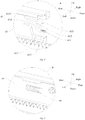
Fig. 2 is an enlarged view of part A inFig. 1 . -
Fig. 3 is an enlarged view of part B inFig. 1 . -
Fig. 4 is a schematic view of a door body of a refrigeration apparatus according to an embodiment of the present disclosure from a viewing angle, in which the door body is located in a first position. -
Fig. 5 is a schematic view of a door body of a refrigeration apparatus according to an embodiment of the present disclosure from another viewing angle, in which the door body is located in a first position. -
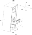
Fig. 6 is a schematic view of a refrigeration apparatus according to an embodiment of the present disclosure, in which a door body is located between a first position and a second position. -
Fig. 7 is a schematic view of a door body of a refrigeration apparatus according to an embodiment of the present disclosure, in which the door body is located in a second position. -
Fig. 8 is a sectional view ofFig. 7 along a C-C direction. -
Fig. 9 is a partially enlarged view of part D inFig. 8 . -
Fig. 10 is a schematic view of a door body of a refrigeration apparatus according to an embodiment of the present disclosure, in which the door body is located beyond a second position. -
Fig. 11 is a sectional view ofFig. 10 along an E-E direction. -
Fig. 12 is a partially enlarged view of part F inFig. 11 . -
refrigeration apparatus 100,cabinet 1,door body 2,drawer 3, first snap assembly 4,hook 41, pressingpart 411, lighteninghole 412,guide surface 413,protrusion 42,second snap assembly 5, snap 51,slot 52,slide rail assembly 6,slide rail support 61,recess 611, protrudingpart 612,side wall 613,slide rail 62. - Embodiments of the present disclosure will be described below in detail, and examples of the embodiments will be illustrated in the accompanying drawings. The embodiments described with reference to the drawings are explanatory and intended to interpret the present disclosure, and should not be constructed to limit the present disclosure.
- A
refrigeration apparatus 100 can refrigerate and store goods that need to be stored at a low temperature. Optionally, therefrigeration apparatus 100 can be a refrigerator, a freezer, a refrigeration cabinet and the like. - The
refrigeration apparatus 100 according to embodiments of the present disclosure will be described below with reference toFigs. 1-12 . As illustrated inFigs. 1-12 , therefrigeration apparatus 100 according to embodiments of the present disclosure includes acabinet 1, adoor body 2, adrawer 3, a first snap assembly 4 and asecond snap assembly 5. - The
door body 2 is provided to thecabinet 1 in a drawable manner, and thedrawer 3 is detachably provided to thedoor body 2. When thedrawer 3 is required to store goods, thedrawer 3 can be mounted to thedoor body 2; when thedrawer 3 needs to be cleaned, thedrawer 3 can be detached from thedoor body 2; when thedoor body 2 or an interior of thecabinet 1 needs to be repaired, thedoor body 2 can be drawn out of thecabinet 1, that is, thedoor body 2 can be separated from thecabinet 1. - The first snap assembly 4 is configured to limit the
door body 2 at a first position where thedoor body 2 may be fixed to thecabinet 1, that is, when thedoor body 2 is located in the first position, the first snap assembly 4 functions, and thedoor body 2 and thecabinet 1 are fixed by the first snap assembly 4. - The
second snap assembly 5 is configured to limit thedoor body 2 at a second position where thedoor body 2 may be fixed to thecabinet 1, that is, when thedoor body 2 is located in the second position, thesecond snap assembly 5 functions, and thedoor body 2 and thecabinet 1 are fixed by thesecond snap assembly 5. - In a process of pulling the
door body 2 out of thecabinet 1, thedoor body 2 passes through the first position and the second position sequentially; when the first snap assembly 4 fails, thedrawer 3 is adapted to be taken out of thedoor body 2; when thesecond snap assembly 5 fails, thedoor body 2 is adapted to be separated from thecabinet 1. - The process of pulling the
door body 2 out of thecabinet 1 is presented as follows. - When it is only necessary to open the
door body 2 to take or place the goods in thedrawer 3, thedoor body 2 is pulled back; as illustrated inFigs. 4 and 5 , when thedoor body 2 is pulled to the first position, the first snap assembly 4 functions to fix thedoor body 2 and thecabinet 1. - When the
drawer 3 needs to be taken out, thedoor body 2 is first pulled to the first position, and then the first snap assembly 4 is operated to be disabled, i.e. thedoor body 2 is again movable relative to thecabinet 1; hence, thedoor body 2 is pulled again to a desired position, and as illustrated inFig. 6 , thedrawer 3 can be rotatably taken out, which facilitates cleaning. - When the
door body 2 needs to be separated from thecabinet 1, thedoor body 2 is first pulled to the first position illustrated inFigs. 4 and 5 ; then the first snap assembly 4 is operated to be disabled, so as to continue pulling thedoor body 2 until it reaches the second position illustrated inFigs. 7 and 8 ; thesecond snap assembly 5 is then operated to be disabled, i.e. thedoor body 2 is again movable relative to thecabinet 1; as illustrated inFig. 10 , thedoor body 2 is pulled again to be separated from thecabinet 1, thereby facilitating repair on thedoor body 2 or the interior of thecabinet 1. - It is known from the above description that the first snap assembly 4 and the
second snap assembly 5 both have to be disabled if it is intended to separate thedoor body 2 wholly from thecabinet 1. - It could be understood that the
door body 2 is capable of being fixed to thecabinet 1 in two positions; when thedoor body 2 is fixed in the first position, a distance between thedoor body 2 and thecabinet 1 is relatively small, which only satisfies a requirement of taking or placing part of goods, but when thedoor body 2 is fixed in the second position, the distance between thedoor body 2 and thecabinet 1 is enlarged, which can satisfies a requirement of taking or placing some goods with relatively large volume. - A process of closing the
door body 2 is opposite the above process of pulling thedoor body 2 out of thecabinet 1, which can be known by those skilled in the art based on the above description, and hence will not be elaborated herein. - For the
refrigeration apparatus 100 according to embodiments of the present disclosure, two stages of snap assemblies are provided on a path of relative movement between thedoor body 2 and thecabinet 1, three states, in which thedoor body 2 is opened or closed normally, thedrawer 3 is taken out of thedoor body 2 easily, and thedoor body 2 is separated from thecabinet 1 easily, can be realized when the requirement of taking or placing goods with different volumes is also satisfied. Furthermore, when the first snap assembly 4 is damaged or fails, thesecond snap assembly 5 can still function to prevent theentire door body 2 from being brought out when thedoor body 2 is pulled out to remove thedrawer 3, thereby avoiding damage to personnel and therefrigeration apparatus 100. The refrigeration apparatus according to embodiments of the present disclosure is convenient to use and has high safety. - Some specific embodiments of the
refrigeration apparatus 100 according to the present disclosure will be described with reference toFigs. 1-12 . As illustrated inFigs. 1-12 , therefrigeration apparatus 100 includes thecabinet 1, thedoor body 2, thedrawer 3, the first snap assembly 4, thesecond snap assembly 5 and aslide rail assembly 6. - Optionally, the
refrigeration apparatus 100 is configured as a refrigerator, and thedoor body 2 is configured as adoor body 2 of a freezer door of the refrigerator. - As illustrated in
Fig. 1 , thedoor body 2 is provided to thecabinet 1 in a drawable manner by means of theslide rail assembly 6. Thedrawer 3 is detachably provided to thedoor body 2. - The
slide rail assembly 6 includes aslide rail support 61 and aslide rail 62, and theslide rail support 61 is fixed to an inner wall of thecabinet 1. Theslide rail 62 is fixed to thedoor body 2 and movably connected with theslide rail support 61, that is, theslide rail 62 is movable relative to theslide rail support 61, and theslide rail support 61 is configured to support the slide rail 62.Theslide rail 62 can be a multistage slide rail, such that the stroke can be adjusted. By providing theslide rail assembly 6 between thecabinet 1 and thedoor body 2, thedoor body 2 can be pulled relative to thecabinet 1 more smoothly and can be supported on thecabinet 1 more stably. - Optionally, the
slide rail support 61 can be fixed to thecabinet 1 by a threaded connection, such that the installation of theslide rail assembly 61 is more convenient. Certainly, theslide rail support 61 can be integrally formed with thecabinet 1. - Further optionally, the
slide rail support 61 can be a plastic part, and theslide rail 62 can be a metal slide rail. Such a material setting makes it easy to manufacture and low in production cost. - It could be understood that the
slide rail support 61 and theslide rail 62 each include two portions symmetrically arranged in a width direction of therefrigeration apparatus 100. - The first snap assembly 4 is configured to limit the
door body 2 at the first position where thedoor body 2 may be fixed to thecabinet 1, and preferably, a part of the first snap assembly 4 adapted to be operated is provided at an edge of thecabinet 1 adjacent to thedoor body 2. "The part of the first snap assembly 4 adapted to be operated" refers to a part that can be operated to disable the first snap assembly 4 so as to make thedoor body 2 movable relative to thecabinet 1 and that will be exposed when thedoor body 2 is pulled out of thecabinet 1, that is, when thedoor body 2 is pulled out, thedoor body 2 is spaced apart from thecabinet 1, and at this time, the part for operating and disabling the first snap assembly 4 is exposed. Thus, the operation of the first snap assembly 4 is visualized to facilitate the operation and reduce the probability of damage to components and parts. - As illustrated in
Figs. 1 and2 , the first snap assembly 4 includes two first snapping members that are fitted with each other, and one of the two first snapping members is fixed to theslide rail support 61 while the other one thereof is fixed to a surface of theslide rail 62 facing theslide rail support 61. That is, theslide rail support 61 is fixed to the inner wall of thecabinet 1, theslide rail 62 is located at an inner side of theslide rail support 61, and the two first snapping members are arranged opposite to each other and fitted with each other. When the first snap assembly 4 functions, the two first snapping members are fitted to fix thedoor body 2 and thecabinet 1, i.e. fixing thedoor body 2 at the first position; when the first snap assembly 4 fails, the two first snapping members are gradually separated to make thedoor body 2 movable relative to thecabinet 1. - In some specific examples, as illustrated in
Figs. 1 and2 , one of the two first snapping members is configured as ahook 41 while the other one thereof is configured as aprotrusion 42. Theprotrusion 42 moves along with theslide rail 62, and theslide rail 62 is driven to move by thedoor body 2, such that when theprotrusion 42 is snapped with thehook 41, the first snap assembly 4 functions to fix thedoor body 2 at the first position. When thedoor body 2 continues to move, theprotrusion 42 is released from thehook 41, the first snap assembly 4 fails, and hence thedoor body 2 becomes movable relative to thecabinet 1. - Further, as illustrated in
Fig. 2 , an end of theslide rail support 61 facing thedoor body 2, i.e. a front end of theslide rail support 61, is provided with arecess 611 recessed backwards. A bottom wall of therecess 611 is provided with aprotruding part 612 extending towards thedoor body 2 and spaced apart from twoside walls 613 of therecess 611. That is, the protrudingpart 612 extends forwards from the bottom wall of therecess 611, and in an up-and-down direction, the protrudingpart 612 is located between the twoside walls 613 and spaced apart from both of theside walls 613. - The protruding
part 612 in conjunction with one of the twoside walls 613 of therecess 611 forms thehook 41. As illustrated inFig. 2 , the protrudingpart 612 and anupper side wall 613 of therecess 611 form thehook 41, and theprotruding part 612 and alower side wall 613 of therecess 611 define a space to provide a clearance space for movement of thehook 41. - More specifically, as illustrated in
Fig. 2 , the protrudingpart 612 and theupper side wall 613 of therecess 611 define a U-shaped space with an opening facing forwards; the protrudingpart 612 and thelower side wall 613 of therecess 611 define a substantially Z-shaped space, including two horizontal segments and one connecting segment, in which the connecting segment is inclined forwards and downwards. Thus, the protrudingpart 612 moves more smoothly and does not interfere easily with the twoside walls 613 of therecess 611. - Such a
hook 41 has a simple structure and is easy to form, and the location of thehook 41 facilitates the operation of thehook 41. That is, since thehook 41 is located at the front end of theslide rail support 61, thehook 41 is easy to see when thedoor body 2 is opened. Thus, the process of operating the first snap assembly 4 is visualized, the operation accuracy is high, and the first snap assembly 4 is not easily damaged. - Further, in order to facilitate the operation of the
hook 41, thehook 41 is provided with apressing part 411 adapted to be pressed. In a specific example illustrated inFig. 2 , thepressing part 411 is configured as a cantilever formed on theprotruding part 612 and extending forwards, and an upper surface of the cantilever is an operating surface adapted to be pressed. If it is intended to operate the first snap assembly 4 so as to disable the first snap assembly 4, it is only necessary to press the operating surface, i.e. press down thepressing part 411 to separate thehook 41 from theprotrusion 42. - Certainly, in other embodiments, the protruding
part 612 and thelower side wall 613 of therecess 611 can form thehook 41. In such an embodiment, the protrudingpart 612 and theupper side wall 613 of therecess 611 defines the space that provided the clearance space for the movement of thehook 41. Thepressing part 411 is configured as a cantilever formed on theprotruding part 612 and extending forwards, and a lower surface of the cantilever is an operating surface adapted to be pressed. If it is intended to operate the first snap assembly 4 so as to disable the first snap assembly 4, it is only necessary to press the operating surface, i.e. press thepressing part 411 upwards to separate thehook 41 from theprotrusion 42. - Optionally, the operating surface is configured as a wavy surface to increase friction and facilitate operations of an operator. Certainly, the operating surface can be configured as a plane with a relatively high degree of roughness.
- Further, as illustrated in
Fig. 2 , a middle part of theprotruding part 612 is provided with a lighteninghole 412, thereby ensuring the structural strength of theslide rail support 61 and reducing the weight of theslide rail support 61, in particular, reducing the weight of thehook 41, so as to further facilitate the movement and lightweight of thehook 41. Optionally, the lighteninghole 412 can be one of a triangular hole, a circular hole and a square hole. - Preferably, the most front end of the
protruding part 612 is provided with aguide surface 413, and theguide surface 413 is adapted to fit with theprotrusion 42 to guide theprotrusion 42 into or out of thehook 41. As illustrated inFig. 2 , in the embodiment where theprotruding part 612 and theupper side wall 613 of therecess 611 form thehook 41, theguide surface 413 is formed at the most front end of an upper portion of theprotruding part 612 and is inclined downwards from rear to front; in the embodiment where theprotruding part 612 and thelower side wall 613 of therecess 611 form thehook 41, theguide surface 413 is formed at the most front end of a lower portion of theprotruding part 612 and is inclined upwards from rear to front. Optionally, theguide surface 413 can be a bevel surface or a curved surface. When theguide surface 413 is the bevel surface, it is easier to manufacture; when theguide surface 413 is the curved surface, the transition is smoother and the guiding performance is better. - The
second snap assembly 5 is configured to limit thedoor body 2 at the second position where thedoor body 2 is fixed to thecabinet 1. As illustrated inFigs. 1 and3 , thesecond snap assembly 5 includes two second snapping members that are fitted with each other, and one of the two second snapping members is fixed to theslide rail support 61 while the other one thereof is fixed to the surface of theslide rail 62 facing theslide rail support 61. That is, theslide rail support 61 is fixed to the inner wall of thecabinet 1, theslide rail 62 is located at the inner side of theslide rail support 61, and the two second snapping members are arranged opposite to each other and fitted with each other. When thesecond snap assembly 5 functions, the two second snapping members are fitted to fix thedoor body 2 and thecabinet 1, i.e. fixing thedoor body 2 at the second position; when thesecond snap assembly 5 fails, the two second snapping members are gradually separated to make thedoor body 2 movable relative to thecabinet 1. - In some specific embodiments, as illustrated in
Fig. 3 , one of the two second snapping members is configured as asnap 51, and the other one thereof is configured as aslot 52. More specifically, thesnap 51 is provided to a side surface of theslide rail support 61 opposite to the inner wall of thecabinet 1, and thesnap 51 is configured as a cantilever having an end connected with theslide rail support 61. Preferably, thesnap 51 and theslide rail support 61 are integrally formed by stamping, thereby making it easy to manufacture and low in production cost. - An inner surface of the
snap 51 is provided with a pressing surface adapted to be pressed, and the pressing surface can be configured as a rough surface. - More specifically, as illustrated in
Fig. 1 , theslot 52 is configured as a rectangular hole defined in theslide rail 62, and as illustrated inFig. 3 , thesnap 51 is configured as acuboid snap 51 fitted with the rectangular hole. - It could be understood that the first snapping member and the second snapping member fixed to the
slide rail support 61 are spaced apart along a front-and-rear direction, and the first snapping member is located in front of the second snapping member, i.e. thehook 41 is located in front of thesnap 51; the first snapping member and the second snapping member fixed to theslide rail 62 are spaced apart along the front-and-rear direction, and the first snapping member is located in front of the second snapping member, i.e. theprotrusion 42 is located in front of theslot 52. - Preferably, the
hook 41 and thesnap 51 each are formed with theslide rail support 61 integrally. - With reference to specific structures of the
refrigeration apparatus 100 illustrated inFigs. 1-12 , the process of pulling thedoor body 2 out of thecabinet 1 will be described below in detail. - In general, the
door body 2 sequentially passes through the closed position, the first position and the second position. - The
door body 2 is pulled, and when thedoor body 2 is moved from the closed position to the first position, as illustrated inFigs. 4 and 5 , theprotrusion 42 enters thehook 41 and is engaged with thehook 41 to fix thedoor body 2 and thecabinet 1, in which case goods can be taken out of or placed into thedrawer 3. - The
pressing part 411 of thehook 41 is pressed downwards from the outside of thecabinet 1 to disengage theprotrusion 42 from thehook 41, and thedoor body 2 continues to be pulled, theprotrusion 42 is gradually moved away from thehook 41, and as illustrated inFig. 6 , thedrawer 3 can be taken out, which facilitates the cleaning of thedrawer 3. - The
door body 2 continues to be pulled to the second position, and as illustrated inFigs. 7-9 , thesnap 51 is moved to a position where thesnap 51 is fitted with theslot 52, so as to fix thedoor body 2 and thecabinet 1, in which case goods can be taken out of or placed into thedrawer 3 if thedrawer 3 is still there. - A user may stretch his hand into the
cabinet 1, as illustrated inFigs. 10-12 , press thesnap 51 outwardly to disengage thesnap 51 from theslot 52, and then continue to pull thedoor body 2, such that thesnap 51 is gradually moved away from theslot 52, thedoor body 2 can be wholly separated from thecabinet 1, and theslide rail 62 can be wholly separated from theslide rail support 61. - In short, for the
refrigeration apparatus 100 according to embodiments of the present disclosure, thedoor body 2 is provided to thecabinet 1 in the drawable manner by means of theslide rail assembly 6, thedrawer 3 is detachably provided to thedoor body 2, and two stages of snap assemblies are provided on a path between theslide rail support 61 and theslide rail 62, such that opening and closure of thedoor body 2, the removal of thedrawer 3, the removal of theentire door body 2 can be realized easily. Furthermore, since the two stages of snap assemblies are provided and spaced apart, when the first snap assembly 4 fails or is damaged, thedoor body 2 will not come off thecabinet 1 directly due to a great force exerted by the user, thereby improving the safety, avoiding damage to thedoor body 2 and personnel, indirectly prolonging service life, and facilitating the cleaning of thedrawer 3 and maintenance of therefrigeration apparatus 100. - In the specification, it is to be understood that terms such as "upper," "lower," "front," "rear," "left," "right," "inner," and "outer" should be construed to refer to the orientation as then described or as illustrated in the drawings under discussion for simplifying the description of the present disclosure, but do not alone indicate or imply that the device or element referred to must have a particular orientation or be constructed or operated in a particular orientation. Thus, these terms cannot be constructed to limit the present disclosure.
- In addition, terms such as "first" and "second" are used herein for purposes of description and are not intended to indicate or imply relative importance or significance or to imply the number of indicated technical features. Thus, the feature defined with "first" and "second" may comprise one or more of this feature. In the description of the present disclosure, "a plurality of' means two or more than two, such as two, three, etc., unless specified otherwise.
- In the present disclosure, unless specified or limited otherwise, the terms "mounted," "connected," "coupled," "fixed" and the like are used broadly, and may be, for example, fixed connections, detachable connections, or integral connections; may also be mechanical or electrical connections; may also be direct connections or indirect connections via intervening structures; may also be inner communications of two elements or interactions of two elements, which can be understood by those skilled in the art according to specific situations.
- Reference throughout this specification to "an embodiment," "some embodiments," "an example," "a specific example," or "some examples," means that a particular feature, structure, material, or characteristic described in connection with the embodiment or example is included in at least one embodiment or example of the present disclosure. Thus, the appearances of the phrases in various places throughout this specification are not necessarily referring to the same embodiment or example of the present disclosure. Furthermore, the particular features, structures, materials, or characteristics may be combined in any suitable manner in one or more embodiments or examples. In the absence of mutual contradiction, those skilled in the art can combine and combine the different embodiments or examples described in this specification and the features of different embodiments or examples.
- Although explanatory embodiments have been illustrated and described, it would be appreciated by those skilled in the art that the above embodiments are explanatory and cannot be construed to limit the present disclosure, and changes, modifications, alternatives and variants can be made in the embodiments within the scope of the present disclosure.
Claims (10)
- A refrigeration apparatus, comprising:a cabinet;a door body provided to the cabinet in a drawable manner;a drawer detachably provided to the door body;a first snap assembly adapted to limit the door body at a first position where the door body is fixed to the cabinet;a second snap assembly adapted to limit the door body at a second position where the door body is fixed to the cabinet;the door body passing through the first position and the second position sequentially in a process of pulling the door body out of the cabinet, the drawer being adapted to be pulled out of the door body when the first snap assembly fails, and the door body being adapted to be separated from the cabinet when the second snap assembly fails.
- The refrigeration apparatus according to claim 1, further comprising:
a slide rail assembly comprising a slide rail support fixed to an inner wall of the cabinet; and a slide rail movably connected with the slide rail support and fixed to the door body. - The refrigeration apparatus according to claim 2, wherein the first snap assembly comprises two first snapping members that are fitted with each other, one of the two first snapping members is fixed to the slide rail support, and the other one thereof is fixed to a surface of the slide rail facing the slide rail support.
- The refrigeration apparatus according to claim 3, wherein the one of the two first snapping members is configured as a hook, while the other one thereof is configured as a protrusion.
- The refrigeration apparatus according to claim 4, wherein an end of the slide rail support facing the door body is provided with a recess recessed backwards, a bottom of the recess is provided with a protruding part that extends towards the door body and is spaced apart from two side walls of the recess, and the protruding part and one side wall of the recess form the hook.
- The refrigeration apparatus according to claim 5, wherein the hook is provided with a pressing part that is adapted to be pressed.
- The refrigeration apparatus according to claim 2, wherein the second snap assembly comprises two second snapping members that are fitted with each other, one of the two second snapping members is fixed to the slide rail support, and the other one thereof is fixed to a surface of the slide rail facing the slide rail support.
- The refrigeration apparatus according to claim 7, wherein the one of the two second snapping members is configured as a snap, while the other one thereof is configured as a slot.
- The refrigeration apparatus according to claim 8, wherein the snap is provided to a side surface of the slide rail support opposite to the inner wall of the cabinet, and the snap is configured as a cantilever having an end connected with the slide rail support.
- The refrigeration apparatus according to any one of claims 1 to 9, wherein a part of the first snap assembly adapted to be operated is provided at an edge of the cabinet adjacent to the door body, and is exposed when the door body is pulled out of the cabinet.
Applications Claiming Priority (2)
| Application Number | Priority Date | Filing Date | Title |
|---|---|---|---|
| CN201610255435.XA CN105865140B (en) | 2016-04-20 | 2016-04-20 | Refrigeration device |
| PCT/CN2016/080699 WO2017181438A1 (en) | 2016-04-20 | 2016-04-29 | Refrigeration device |
Publications (3)
| Publication Number | Publication Date |
|---|---|
| EP3346217A1 true EP3346217A1 (en) | 2018-07-11 |
| EP3346217A4 EP3346217A4 (en) | 2019-02-20 |
| EP3346217B1 EP3346217B1 (en) | 2020-04-22 |
Family
ID=56632794
Family Applications (1)
| Application Number | Title | Priority Date | Filing Date |
|---|---|---|---|
| EP16899025.7A Active EP3346217B1 (en) | 2016-04-20 | 2016-04-29 | Refrigeration device |
Country Status (4)
| Country | Link |
|---|---|
| US (1) | US10295245B2 (en) |
| EP (1) | EP3346217B1 (en) |
| CN (1) | CN105865140B (en) |
| WO (1) | WO2017181438A1 (en) |
Families Citing this family (4)
| Publication number | Priority date | Publication date | Assignee | Title |
|---|---|---|---|---|
| KR102474192B1 (en) * | 2017-11-22 | 2022-12-06 | 엘지전자 주식회사 | Refrigerator |
| CN109813033B (en) * | 2019-03-26 | 2023-11-10 | 长虹美菱股份有限公司 | A refrigerator inner door assembly structure |
| CN112696854B (en) * | 2019-10-23 | 2022-11-25 | 青岛海尔特种电冰柜有限公司 | Slide rail adjusting system and refrigerating device |
| JP7836779B2 (en) * | 2023-02-20 | 2026-03-27 | 日立グローバルライフソリューションズ株式会社 | Automatic drawer door assembly device and automatic drawer door assembly method |
Family Cites Families (13)
| Publication number | Priority date | Publication date | Assignee | Title |
|---|---|---|---|---|
| US6971730B2 (en) * | 2002-03-15 | 2005-12-06 | Maytag Corporation | Freezer drawer support assembly |
| CN2789689Y (en) | 2005-02-06 | 2006-06-21 | 海尔集团公司 | Fixing device for slideway and electric refrigerator set with the same device |
| US7406833B2 (en) | 2005-05-27 | 2008-08-05 | Whirlpool Corporation | Refrigerator storage system |
| EP1728996A1 (en) * | 2005-05-31 | 2006-12-06 | Nissan Motor Co., Ltd. | Combustion control method and apparatus for a direct injection spark ignition internal combustion engine |
| KR20090133009A (en) * | 2008-06-23 | 2009-12-31 | 엘지전자 주식회사 | Drawer of refrigerator |
| CN101596045A (en) * | 2009-06-25 | 2009-12-09 | 朱建华 | Detachable drawer slide |
| CN103026157B (en) * | 2010-07-30 | 2015-06-03 | 松下电器产业株式会社 | Cold storage |
| CN102147184B (en) * | 2011-04-13 | 2013-04-17 | 合肥美的荣事达电冰箱有限公司 | Drawer component for refrigerating plant and refrigerating plant comprising same |
| CN202126134U (en) | 2011-06-03 | 2012-01-25 | 海尔集团公司 | Drawer assembly for refrigerator and refrigerator with same |
| CN104172760B (en) | 2013-05-22 | 2017-08-29 | 苏州南俊商贸有限公司 | Push type Anti-extrusion slide rail |
| KR101641263B1 (en) * | 2014-12-23 | 2016-07-20 | 엘지전자 주식회사 | Refrigerator |
| US10012431B2 (en) * | 2016-03-07 | 2018-07-03 | Haier Us Appliance Solutions, Inc. | Refrigerator appliance with a drawer slide synchronizer |
| US9939014B1 (en) * | 2017-05-09 | 2018-04-10 | Nan Juen International Co., Ltd. | Slide rail displacement positioning mechanism |
-
2016
- 2016-04-20 CN CN201610255435.XA patent/CN105865140B/en active Active
- 2016-04-29 WO PCT/CN2016/080699 patent/WO2017181438A1/en not_active Ceased
- 2016-04-29 EP EP16899025.7A patent/EP3346217B1/en active Active
- 2016-04-29 US US15/765,273 patent/US10295245B2/en active Active
Also Published As
| Publication number | Publication date |
|---|---|
| CN105865140B (en) | 2020-04-17 |
| US20190049171A1 (en) | 2019-02-14 |
| CN105865140A (en) | 2016-08-17 |
| EP3346217B1 (en) | 2020-04-22 |
| WO2017181438A1 (en) | 2017-10-26 |
| US10295245B2 (en) | 2019-05-21 |
| EP3346217A4 (en) | 2019-02-20 |
Similar Documents
| Publication | Publication Date | Title |
|---|---|---|
| EP3346217B1 (en) | Refrigeration device | |
| KR101592573B1 (en) | Refrigerator | |
| EP3904800B1 (en) | Refrigerator having a slide rail cabling mechanism | |
| CN208736030U (en) | A universal drawer for refrigerator | |
| US9585474B2 (en) | Traveling harness system | |
| CN101170927B (en) | Household appliances with telescopic drawers | |
| KR101695808B1 (en) | A refrigerator | |
| US10234190B2 (en) | Locking assemblies for door-in-door refrigerator appliances | |
| EP2690384B1 (en) | Refrigerator | |
| EP1953482A2 (en) | Electric box and cooling storage | |
| CN102135363A (en) | Refrigerating equipment and folding storage rack thereof | |
| KR20110010405A (en) | Refrigerator | |
| CN107142678B (en) | Wall-mounted washing machine | |
| JPH11325712A (en) | refrigerator | |
| CN203216203U (en) | Refrigerator | |
| KR101461963B1 (en) | Refrigerator drawer | |
| CN103162503A (en) | Refrigerator | |
| CN102353222A (en) | Refrigerator | |
| CN107631542A (en) | A kind of rack component and the refrigerator with the rack component | |
| CN102235799B (en) | Slide rail assembly for refrigerator drawer and refrigerator with slide rail assembly | |
| EP3637026A1 (en) | Refrigerator air-channel air supply volume adjustable structure and refrigerator | |
| CN204902413U (en) | A drawer components and refrigeration plant for refrigeration plant | |
| CN106030228B (en) | Domestic refrigerator with interior room can movably be disposed with load-bearing part in the interior room, be disposed with container to movement coupling on the load-bearing part | |
| KR101022040B1 (en) | Case foam mold for refrigerator | |
| CN102538348B (en) | refrigerator |
Legal Events
| Date | Code | Title | Description |
|---|---|---|---|
| STAA | Information on the status of an ep patent application or granted ep patent |
Free format text: STATUS: THE INTERNATIONAL PUBLICATION HAS BEEN MADE |
|
| PUAI | Public reference made under article 153(3) epc to a published international application that has entered the european phase |
Free format text: ORIGINAL CODE: 0009012 |
|
| STAA | Information on the status of an ep patent application or granted ep patent |
Free format text: STATUS: REQUEST FOR EXAMINATION WAS MADE |
|
| 17P | Request for examination filed |
Effective date: 20180405 |
|
| AK | Designated contracting states |
Kind code of ref document: A1 Designated state(s): AL AT BE BG CH CY CZ DE DK EE ES FI FR GB GR HR HU IE IS IT LI LT LU LV MC MK MT NL NO PL PT RO RS SE SI SK SM TR |
|
| AX | Request for extension of the european patent |
Extension state: BA ME |
|
| A4 | Supplementary search report drawn up and despatched |
Effective date: 20190121 |
|
| RIC1 | Information provided on ipc code assigned before grant |
Ipc: F25D 25/02 20060101AFI20190115BHEP |
|
| DAV | Request for validation of the european patent (deleted) | ||
| DAX | Request for extension of the european patent (deleted) | ||
| GRAP | Despatch of communication of intention to grant a patent |
Free format text: ORIGINAL CODE: EPIDOSNIGR1 |
|
| STAA | Information on the status of an ep patent application or granted ep patent |
Free format text: STATUS: GRANT OF PATENT IS INTENDED |
|
| INTG | Intention to grant announced |
Effective date: 20191106 |
|
| GRAS | Grant fee paid |
Free format text: ORIGINAL CODE: EPIDOSNIGR3 |
|
| GRAA | (expected) grant |
Free format text: ORIGINAL CODE: 0009210 |
|
| STAA | Information on the status of an ep patent application or granted ep patent |
Free format text: STATUS: THE PATENT HAS BEEN GRANTED |
|
| AK | Designated contracting states |
Kind code of ref document: B1 Designated state(s): AL AT BE BG CH CY CZ DE DK EE ES FI FR GB GR HR HU IE IS IT LI LT LU LV MC MK MT NL NO PL PT RO RS SE SI SK SM TR |
|
| REG | Reference to a national code |
Ref country code: CH Ref legal event code: EP |
|
| REG | Reference to a national code |
Ref country code: IE Ref legal event code: FG4D |
|
| REG | Reference to a national code |
Ref country code: DE Ref legal event code: R096 Ref document number: 602016034838 Country of ref document: DE |
|
| REG | Reference to a national code |
Ref country code: AT Ref legal event code: REF Ref document number: 1260670 Country of ref document: AT Kind code of ref document: T Effective date: 20200515 |
|
| REG | Reference to a national code |
Ref country code: LT Ref legal event code: MG4D |
|
| REG | Reference to a national code |
Ref country code: NL Ref legal event code: MP Effective date: 20200422 |
|
| PG25 | Lapsed in a contracting state [announced via postgrant information from national office to epo] |
Ref country code: FI Free format text: LAPSE BECAUSE OF FAILURE TO SUBMIT A TRANSLATION OF THE DESCRIPTION OR TO PAY THE FEE WITHIN THE PRESCRIBED TIME-LIMIT Effective date: 20200422 Ref country code: NO Free format text: LAPSE BECAUSE OF FAILURE TO SUBMIT A TRANSLATION OF THE DESCRIPTION OR TO PAY THE FEE WITHIN THE PRESCRIBED TIME-LIMIT Effective date: 20200722 Ref country code: GR Free format text: LAPSE BECAUSE OF FAILURE TO SUBMIT A TRANSLATION OF THE DESCRIPTION OR TO PAY THE FEE WITHIN THE PRESCRIBED TIME-LIMIT Effective date: 20200723 Ref country code: PT Free format text: LAPSE BECAUSE OF FAILURE TO SUBMIT A TRANSLATION OF THE DESCRIPTION OR TO PAY THE FEE WITHIN THE PRESCRIBED TIME-LIMIT Effective date: 20200824 Ref country code: NL Free format text: LAPSE BECAUSE OF FAILURE TO SUBMIT A TRANSLATION OF THE DESCRIPTION OR TO PAY THE FEE WITHIN THE PRESCRIBED TIME-LIMIT Effective date: 20200422 Ref country code: LT Free format text: LAPSE BECAUSE OF FAILURE TO SUBMIT A TRANSLATION OF THE DESCRIPTION OR TO PAY THE FEE WITHIN THE PRESCRIBED TIME-LIMIT Effective date: 20200422 Ref country code: SE Free format text: LAPSE BECAUSE OF FAILURE TO SUBMIT A TRANSLATION OF THE DESCRIPTION OR TO PAY THE FEE WITHIN THE PRESCRIBED TIME-LIMIT Effective date: 20200422 Ref country code: IS Free format text: LAPSE BECAUSE OF FAILURE TO SUBMIT A TRANSLATION OF THE DESCRIPTION OR TO PAY THE FEE WITHIN THE PRESCRIBED TIME-LIMIT Effective date: 20200822 |
|
| REG | Reference to a national code |
Ref country code: AT Ref legal event code: MK05 Ref document number: 1260670 Country of ref document: AT Kind code of ref document: T Effective date: 20200422 |
|
| PG25 | Lapsed in a contracting state [announced via postgrant information from national office to epo] |
Ref country code: HR Free format text: LAPSE BECAUSE OF FAILURE TO SUBMIT A TRANSLATION OF THE DESCRIPTION OR TO PAY THE FEE WITHIN THE PRESCRIBED TIME-LIMIT Effective date: 20200422 Ref country code: LV Free format text: LAPSE BECAUSE OF FAILURE TO SUBMIT A TRANSLATION OF THE DESCRIPTION OR TO PAY THE FEE WITHIN THE PRESCRIBED TIME-LIMIT Effective date: 20200422 Ref country code: BG Free format text: LAPSE BECAUSE OF FAILURE TO SUBMIT A TRANSLATION OF THE DESCRIPTION OR TO PAY THE FEE WITHIN THE PRESCRIBED TIME-LIMIT Effective date: 20200722 Ref country code: RS Free format text: LAPSE BECAUSE OF FAILURE TO SUBMIT A TRANSLATION OF THE DESCRIPTION OR TO PAY THE FEE WITHIN THE PRESCRIBED TIME-LIMIT Effective date: 20200422 |
|
| REG | Reference to a national code |
Ref country code: CH Ref legal event code: PL |
|
| PG25 | Lapsed in a contracting state [announced via postgrant information from national office to epo] |
Ref country code: AL Free format text: LAPSE BECAUSE OF FAILURE TO SUBMIT A TRANSLATION OF THE DESCRIPTION OR TO PAY THE FEE WITHIN THE PRESCRIBED TIME-LIMIT Effective date: 20200422 |
|
| REG | Reference to a national code |
Ref country code: DE Ref legal event code: R097 Ref document number: 602016034838 Country of ref document: DE |
|
| PG25 | Lapsed in a contracting state [announced via postgrant information from national office to epo] |
Ref country code: ES Free format text: LAPSE BECAUSE OF FAILURE TO SUBMIT A TRANSLATION OF THE DESCRIPTION OR TO PAY THE FEE WITHIN THE PRESCRIBED TIME-LIMIT Effective date: 20200422 Ref country code: MC Free format text: LAPSE BECAUSE OF FAILURE TO SUBMIT A TRANSLATION OF THE DESCRIPTION OR TO PAY THE FEE WITHIN THE PRESCRIBED TIME-LIMIT Effective date: 20200422 Ref country code: CZ Free format text: LAPSE BECAUSE OF FAILURE TO SUBMIT A TRANSLATION OF THE DESCRIPTION OR TO PAY THE FEE WITHIN THE PRESCRIBED TIME-LIMIT Effective date: 20200422 Ref country code: LI Free format text: LAPSE BECAUSE OF NON-PAYMENT OF DUE FEES Effective date: 20200430 Ref country code: CH Free format text: LAPSE BECAUSE OF NON-PAYMENT OF DUE FEES Effective date: 20200430 Ref country code: RO Free format text: LAPSE BECAUSE OF FAILURE TO SUBMIT A TRANSLATION OF THE DESCRIPTION OR TO PAY THE FEE WITHIN THE PRESCRIBED TIME-LIMIT Effective date: 20200422 Ref country code: LU Free format text: LAPSE BECAUSE OF NON-PAYMENT OF DUE FEES Effective date: 20200429 Ref country code: EE Free format text: LAPSE BECAUSE OF FAILURE TO SUBMIT A TRANSLATION OF THE DESCRIPTION OR TO PAY THE FEE WITHIN THE PRESCRIBED TIME-LIMIT Effective date: 20200422 Ref country code: AT Free format text: LAPSE BECAUSE OF FAILURE TO SUBMIT A TRANSLATION OF THE DESCRIPTION OR TO PAY THE FEE WITHIN THE PRESCRIBED TIME-LIMIT Effective date: 20200422 Ref country code: IT Free format text: LAPSE BECAUSE OF FAILURE TO SUBMIT A TRANSLATION OF THE DESCRIPTION OR TO PAY THE FEE WITHIN THE PRESCRIBED TIME-LIMIT Effective date: 20200422 Ref country code: SM Free format text: LAPSE BECAUSE OF FAILURE TO SUBMIT A TRANSLATION OF THE DESCRIPTION OR TO PAY THE FEE WITHIN THE PRESCRIBED TIME-LIMIT Effective date: 20200422 Ref country code: DK Free format text: LAPSE BECAUSE OF FAILURE TO SUBMIT A TRANSLATION OF THE DESCRIPTION OR TO PAY THE FEE WITHIN THE PRESCRIBED TIME-LIMIT Effective date: 20200422 |
|
| REG | Reference to a national code |
Ref country code: BE Ref legal event code: MM Effective date: 20200430 |
|
| PG25 | Lapsed in a contracting state [announced via postgrant information from national office to epo] |
Ref country code: BE Free format text: LAPSE BECAUSE OF NON-PAYMENT OF DUE FEES Effective date: 20200430 Ref country code: SK Free format text: LAPSE BECAUSE OF FAILURE TO SUBMIT A TRANSLATION OF THE DESCRIPTION OR TO PAY THE FEE WITHIN THE PRESCRIBED TIME-LIMIT Effective date: 20200422 Ref country code: PL Free format text: LAPSE BECAUSE OF FAILURE TO SUBMIT A TRANSLATION OF THE DESCRIPTION OR TO PAY THE FEE WITHIN THE PRESCRIBED TIME-LIMIT Effective date: 20200422 |
|
| PLBE | No opposition filed within time limit |
Free format text: ORIGINAL CODE: 0009261 |
|
| STAA | Information on the status of an ep patent application or granted ep patent |
Free format text: STATUS: NO OPPOSITION FILED WITHIN TIME LIMIT |
|
| 26N | No opposition filed |
Effective date: 20210125 |
|
| PG25 | Lapsed in a contracting state [announced via postgrant information from national office to epo] |
Ref country code: IE Free format text: LAPSE BECAUSE OF NON-PAYMENT OF DUE FEES Effective date: 20200429 |
|
| PG25 | Lapsed in a contracting state [announced via postgrant information from national office to epo] |
Ref country code: SI Free format text: LAPSE BECAUSE OF FAILURE TO SUBMIT A TRANSLATION OF THE DESCRIPTION OR TO PAY THE FEE WITHIN THE PRESCRIBED TIME-LIMIT Effective date: 20200422 |
|
| PG25 | Lapsed in a contracting state [announced via postgrant information from national office to epo] |
Ref country code: TR Free format text: LAPSE BECAUSE OF FAILURE TO SUBMIT A TRANSLATION OF THE DESCRIPTION OR TO PAY THE FEE WITHIN THE PRESCRIBED TIME-LIMIT Effective date: 20200422 Ref country code: MT Free format text: LAPSE BECAUSE OF FAILURE TO SUBMIT A TRANSLATION OF THE DESCRIPTION OR TO PAY THE FEE WITHIN THE PRESCRIBED TIME-LIMIT Effective date: 20200422 Ref country code: CY Free format text: LAPSE BECAUSE OF FAILURE TO SUBMIT A TRANSLATION OF THE DESCRIPTION OR TO PAY THE FEE WITHIN THE PRESCRIBED TIME-LIMIT Effective date: 20200422 |
|
| PG25 | Lapsed in a contracting state [announced via postgrant information from national office to epo] |
Ref country code: MK Free format text: LAPSE BECAUSE OF FAILURE TO SUBMIT A TRANSLATION OF THE DESCRIPTION OR TO PAY THE FEE WITHIN THE PRESCRIBED TIME-LIMIT Effective date: 20200422 |
|
| PGFP | Annual fee paid to national office [announced via postgrant information from national office to epo] |
Ref country code: DE Payment date: 20250417 Year of fee payment: 10 |
|
| PGFP | Annual fee paid to national office [announced via postgrant information from national office to epo] |
Ref country code: FR Payment date: 20250430 Year of fee payment: 10 |
|
| PGFP | Annual fee paid to national office [announced via postgrant information from national office to epo] |
Ref country code: GB Payment date: 20260327 Year of fee payment: 11 |