EP3346212A1 - Air-cooled refrigerator - Google Patents
Air-cooled refrigerator Download PDFInfo
- Publication number
- EP3346212A1 EP3346212A1 EP15902674.9A EP15902674A EP3346212A1 EP 3346212 A1 EP3346212 A1 EP 3346212A1 EP 15902674 A EP15902674 A EP 15902674A EP 3346212 A1 EP3346212 A1 EP 3346212A1
- Authority
- EP
- European Patent Office
- Prior art keywords
- sub
- groove
- disposed
- air
- electrical damper
- Prior art date
- Legal status (The legal status is an assumption and is not a legal conclusion. Google has not performed a legal analysis and makes no representation as to the accuracy of the status listed.)
- Granted
Links
Images


Classifications
-
- F—MECHANICAL ENGINEERING; LIGHTING; HEATING; WEAPONS; BLASTING
- F25—REFRIGERATION OR COOLING; COMBINED HEATING AND REFRIGERATION SYSTEMS; HEAT PUMP SYSTEMS; MANUFACTURE OR STORAGE OF ICE; LIQUEFACTION SOLIDIFICATION OF GASES
- F25D—REFRIGERATORS; COLD ROOMS; ICE-BOXES; COOLING OR FREEZING APPARATUS NOT OTHERWISE PROVIDED FOR
- F25D11/00—Self-contained movable devices, e.g. domestic refrigerators
- F25D11/02—Self-contained movable devices, e.g. domestic refrigerators with cooling compartments at different temperatures
-
- F—MECHANICAL ENGINEERING; LIGHTING; HEATING; WEAPONS; BLASTING
- F25—REFRIGERATION OR COOLING; COMBINED HEATING AND REFRIGERATION SYSTEMS; HEAT PUMP SYSTEMS; MANUFACTURE OR STORAGE OF ICE; LIQUEFACTION SOLIDIFICATION OF GASES
- F25D—REFRIGERATORS; COLD ROOMS; ICE-BOXES; COOLING OR FREEZING APPARATUS NOT OTHERWISE PROVIDED FOR
- F25D17/00—Arrangements for circulating cooling fluids; Arrangements for circulating gas, e.g. air, within refrigerated spaces
- F25D17/04—Arrangements for circulating cooling fluids; Arrangements for circulating gas, e.g. air, within refrigerated spaces for circulating air, e.g. by convection
- F25D17/042—Air treating means within refrigerated spaces
- F25D17/045—Air flow control arrangements
-
- F—MECHANICAL ENGINEERING; LIGHTING; HEATING; WEAPONS; BLASTING
- F25—REFRIGERATION OR COOLING; COMBINED HEATING AND REFRIGERATION SYSTEMS; HEAT PUMP SYSTEMS; MANUFACTURE OR STORAGE OF ICE; LIQUEFACTION SOLIDIFICATION OF GASES
- F25D—REFRIGERATORS; COLD ROOMS; ICE-BOXES; COOLING OR FREEZING APPARATUS NOT OTHERWISE PROVIDED FOR
- F25D17/00—Arrangements for circulating cooling fluids; Arrangements for circulating gas, e.g. air, within refrigerated spaces
- F25D17/04—Arrangements for circulating cooling fluids; Arrangements for circulating gas, e.g. air, within refrigerated spaces for circulating air, e.g. by convection
- F25D17/06—Arrangements for circulating cooling fluids; Arrangements for circulating gas, e.g. air, within refrigerated spaces for circulating air, e.g. by convection by forced circulation
-
- F—MECHANICAL ENGINEERING; LIGHTING; HEATING; WEAPONS; BLASTING
- F25—REFRIGERATION OR COOLING; COMBINED HEATING AND REFRIGERATION SYSTEMS; HEAT PUMP SYSTEMS; MANUFACTURE OR STORAGE OF ICE; LIQUEFACTION SOLIDIFICATION OF GASES
- F25D—REFRIGERATORS; COLD ROOMS; ICE-BOXES; COOLING OR FREEZING APPARATUS NOT OTHERWISE PROVIDED FOR
- F25D17/00—Arrangements for circulating cooling fluids; Arrangements for circulating gas, e.g. air, within refrigerated spaces
- F25D17/04—Arrangements for circulating cooling fluids; Arrangements for circulating gas, e.g. air, within refrigerated spaces for circulating air, e.g. by convection
- F25D17/06—Arrangements for circulating cooling fluids; Arrangements for circulating gas, e.g. air, within refrigerated spaces for circulating air, e.g. by convection by forced circulation
- F25D17/062—Arrangements for circulating cooling fluids; Arrangements for circulating gas, e.g. air, within refrigerated spaces for circulating air, e.g. by convection by forced circulation in household refrigerators
- F25D17/065—Arrangements for circulating cooling fluids; Arrangements for circulating gas, e.g. air, within refrigerated spaces for circulating air, e.g. by convection by forced circulation in household refrigerators with compartments at different temperatures
-
- F—MECHANICAL ENGINEERING; LIGHTING; HEATING; WEAPONS; BLASTING
- F25—REFRIGERATION OR COOLING; COMBINED HEATING AND REFRIGERATION SYSTEMS; HEAT PUMP SYSTEMS; MANUFACTURE OR STORAGE OF ICE; LIQUEFACTION SOLIDIFICATION OF GASES
- F25D—REFRIGERATORS; COLD ROOMS; ICE-BOXES; COOLING OR FREEZING APPARATUS NOT OTHERWISE PROVIDED FOR
- F25D23/00—General constructional features
- F25D23/003—General constructional features for cooling refrigerating machinery
-
- F—MECHANICAL ENGINEERING; LIGHTING; HEATING; WEAPONS; BLASTING
- F25—REFRIGERATION OR COOLING; COMBINED HEATING AND REFRIGERATION SYSTEMS; HEAT PUMP SYSTEMS; MANUFACTURE OR STORAGE OF ICE; LIQUEFACTION SOLIDIFICATION OF GASES
- F25D—REFRIGERATORS; COLD ROOMS; ICE-BOXES; COOLING OR FREEZING APPARATUS NOT OTHERWISE PROVIDED FOR
- F25D2317/00—Details or arrangements for circulating cooling fluids; Details or arrangements for circulating gas, e.g. air, within refrigerated spaces, not provided for in other groups of this subclass
- F25D2317/06—Details or arrangements for circulating cooling fluids; Details or arrangements for circulating gas, e.g. air, within refrigerated spaces, not provided for in other groups of this subclass with forced air circulation
- F25D2317/061—Details or arrangements for circulating cooling fluids; Details or arrangements for circulating gas, e.g. air, within refrigerated spaces, not provided for in other groups of this subclass with forced air circulation through special compartments
Definitions
- the present disclosure relates to a field of household appliances, and specifically to an air-cooled refrigerator.
- An existing three-door air-cooled refrigerator includes a freezing compartment, a refrigerating compartment and a temperature-variable compartment.
- a freezing compartment In the freezing compartment, there is provided with a dual electrical damper having two air outlets. Cold air in the freezing compartment enters the refrigerating compartment and the temperature-variable compartment correspondingly through the two air outlets of the dual electrical damper.
- the dual electrical damper in the freezing compartment has a defect of tending to be in a control failure.
- a dual electrical damper of an existing three-door air-cooled refrigerator i.e. an air-cooled refrigerator having a freezing compartment, a refrigerating compartment and a temperature-variable compartment
- a dual electrical damper of an existing three-door air-cooled refrigerator tends to be involved in a control failure, causing the refrigerating compartment and the temperature-variable compartment to be unable to perform refrigeration.
- the dual electrical damper tends to frost and ice up, thereby leading the dual electrical damper to a control failure much easily.
- the present disclosure seeks to solve one of the problems existing in the related art to at least some extent. For that reason, the present disclosure provides an air-cooled refrigerator, and an electrical damper of the air-cooled refrigerator doesn't tend to be involved in a control failure.
- the air-cooled refrigerator includes a housing; a freezing inner container, a temperature-variable inner container and a refrigerating inner container disposed in the housing at intervals in an up and down direction, in which a wall of the temperature-variable inner container is provided with a temperature-variable air inlet, a wall of the refrigerating inner container is provided with a refrigerating air inlet, and a wall of the freezing inner container is provided with an air outlet; a foaming layer filled in a space between the housing and the freezing inner container, the temperature-variable inner container and the refrigerating inner container; an embedded member disposed in the foaming layer; an electrical damper provided to the embedded member and located in the foaming layer, the electrical damper being provided with a cold air inlet and a first cold air outlet and a second cold air outlet in communication with the cold air inlet; a freezing air-outlet passage having a first end connected with the air outlet and a second end connected with the cold air inlet; and a
- the electrical damper of the air-cooled refrigerator according to embodiments of the present disclosure doesn't intend to be involved in the control failure.
- the air-cooled refrigerator according to the above-mentioned embodiments of the present disclosure can also have the following additional technical features.
- the embedded member and the electrical damper are opposite to the temperature-variable inner container or the refrigerating inner container in a horizontal direction.
- the embedded member has a mounting cavity, the mounting cavity having an open end, and at least a part of the electrical damper is disposed in the mounting cavity.
- a wall of the mounting cavity is provided with a horizontal groove and a vertical groove
- an outer surface of the electrical damper is provided with a horizontal convex rib and a vertical convex rib, in which at least a part of the horizontal convex rib is disposed in the horizontal groove, and at least a part of the vertical convex rib is disposed in the vertical groove.
- a shape of the horizontal convex rib is adapted to a shape of the horizontal groove
- a shape of the vertical convex rib is adapted to a shape of the vertical groove
- the horizontal groove includes a first sub-groove disposed to a first side wall of the mounting cavity, a second sub-groove disposed to a second side wall of the mounting cavity, and a third sub-groove disposed to a rear wall of the mounting cavity, the third sub-groove having a first end connected with an end of the first sub-groove and a second end connected with an end of the second sub-groove, in which the vertical groove is disposed in the rear wall of the mounting cavity, and the vertical groove intersects with the third sub-groove to form a cross;
- the horizontal convex rib includes a first convex sub-rib disposed to a first side face of the electrical damper and fitted in the first sub-groove, a second convex sub-rib disposed to a second side face of the electrical damper and fitted in the second sub-groove, and a third convex sub-rib disposed to a rear surface of the electrical damper and fitted in the
- a top wall of the mounting cavity is provided with an upper groove
- a bottom wall of the mounting cavity is provided with a lower groove
- an upper surface of the electrical damper is provided with an upper convex rib
- a lower surface of the electrical damper is provided with a lower convex rib
- the vertical groove has an upper end connected with a rear end of the upper groove and a lower end connected with a rear end of the lower groove
- the vertical convex rib has an upper end connected with a rear end of the upper convex rib and a lower end connected with a rear end of the lower convex rib
- at least a part of the upper convex rib is disposed in the upper groove
- at least a part of the lower convex rib is disposed in the lower groove.
- the electrical damper includes: a body, the body having a cavity therein, and a bottom wall of the cavity being provided with the cold air inlet; and a separating member disposed in the cavity, the separating member dividing the cavity into a first sub-cavity and a second sub-cavity and dividing the cold air inlet into a first cold air sub-inlet communicated with the first sub-cavity and a second cold air sub-inlet communicated with the second sub-cavity, in which a top wall of the first sub-cavity is provided with a first cold air outlet, and a top wall of the second sub-cavity is provided with a second cold air outlet.
- the air-cooled refrigerator further includes an annular sponge piece, the sponge piece being disposed to a front surface and/or an outer circumferential surface of the electrical damper, the sponge piece abutting against the foaming layer.
- a front part of the outer circumferential surface of the electrical damper and/or the front surface of the electrical damper are provided with an annular flange, and the sponge piece is disposed to the flange.
- a dual electrical damper of an existing three-door air-cooled refrigerator i.e. an air-cooled refrigerator having a freezing compartment, a refrigerating compartment and a temperature-variable compartment
- a dual electrical damper of an existing three-door air-cooled refrigerator tends to be involved in a control failure, causing the refrigerating compartment and the temperature-variable compartment to be unable to perform refrigeration.
- the dual electrical damper tends to frost and ice up, thereby leading the dual electrical damper to a control failure much easily.
- the air-cooled refrigerator 10 includes a housing 101, a freezing inner container 1021, a temperature-variable inner container 1022, a refrigerating inner container 1023, a foaming layer 103, an embedded member 104, an electrical damper 105, a freezing air-outlet passage 1061, a temperature-variable air-inlet passage 1062, and a refrigerating air-inlet passage (not shown in the drawings).
- the freezing inner container 1021, the temperature-variable inner container 1022 and the refrigerating inner container 1023 are disposed in the housing 101 at intervals in an up and down direction, a wall of the temperature-variable inner container 1022 is provided with a temperature-variable air inlet, a wall of the refrigerating inner container 1023 is provided with a refrigerating air inlet, and a wall of the freezing inner container 1021 is provided with an air outlet.
- the foaming layer 103 is filled in a space between the housing 101 and the freezing inner container 1021, the temperature-variable inner container 1022 and the refrigerating inner container 1023.
- the embedded member 104 is disposed in the foaming layer 103, the electrical damper 105 is provided to the embedded member 104, the electrical damper 105 is located in the foaming layer 103, the electrical damper 105 is provided with a cold air inlet (not shown in the drawings) and a first cold air outlet 1053 and a second cold air outlet 1054 in communication with the cold air inlet.
- the electrical damper 105 is a dual electrical damper.
- a first end of the freezing air-outlet passage 1061 is connected with the air outlet of the freezing inner container 1021, and a second end of the freezing air-outlet passage 1061 is connected with the cold air inlet of the electrical damper 105.
- a first end of the temperature-variable air-inlet passage 1062 is connected with the first cold air outlet 1053, and a second end of the temperature-variable air-inlet passage 1062 is connected with the temperature-variable air inlet of the temperature-variable inner container 1022.
- a first end of the refrigerating air-inlet passage is connected with the second cold air outlet 1054, and a second end of the refrigerating air-inlet passage is connected with the refrigerating air inlet of the refrigerating inner container 1023.
- the electrical damper 105 by mounting the electrical damper 105 to the embedded member 104 located in the foaming layer 103, the electrical damper 105 can be mounted in the foaming layer 103, therefore it is possible to prevent the electrical damper 105 from being in a low temperature environment, thereby avoiding the electrical damper 105 from being involved in a control failure due to frosting and icing, so as to effectively perform refrigeration in a space of the temperature-variable inner container 1022 and the refrigerating inner container 1023, i.e., effectively performing refrigeration in the refrigerating compartment and the temperature-variable compartment.
- the electrical damper 105 is no longer mounted in the freezing inner container 1021, i.e., the electrical damper 105 is no longer mounted in the freezing compartment, a storage space in the freezing inner container 1021 can be increased. Furthermore, the electrical damper 105 is mounted in the embedded member 104, such that the electrical damper 105 can be mounted more easily and steadily.
- the electrical damper 105 of the air-cooled refrigerator 10 doesn't tend to be involved in the control failure, and the air-cooled refrigerator 10 has advantages of a large storage space, a reasonable structure and the like.
- the refrigerating inner container 1023 can be provided with a refrigerating return air inlet
- the temperature-variable inner container 1022 can be provided with a temperature-variable return air inlet
- the freezing inner container 1021 can be provided with a freezing return air inlet in communication with the refrigerating return air inlet and the temperature-variable return air inlet.
- the air-cooled refrigerator 10 includes the housing 101, the freezing inner container 1021, the temperature-variable inner container 1022, the refrigerating inner container 1023, the foaming layer 103, the embedded member 104, the electrical damper 105, the freezing air-outlet passage 1061, the temperature-variable air-inlet passage 1062, and the refrigerating air-inlet passage (not shown in the drawings).
- the temperature-variable inner container 1022 is disposed above the freezing inner container 1021, and the refrigerating inner container 1023 is disposed above the temperature-variable inner container 1022.
- the freezing inner container 1021 has the freezing compartment therein, the temperature-variable inner container 1022 has the temperature-variable compartment therein, and the refrigerating inner container 1023 has the refrigerating compartment therein.
- the up and down direction is shown by an arrow C in Fig. 1 .
- the foaming layer 103 is filled in the space between the housing 101 and the freezing inner container 1021, the temperature-variable inner container 1022 and the refrigerating inner container 1023.
- the embedded member 104 is disposed in the foaming layer 103, the electrical damper 105 is provided to the embedded member 104, and that is, the electrical damper 105 is also disposed in the foaming layer 103.
- the embedded member 104 and the electrical damper 105 are opposite to the temperature-variable inner container 1022 or the refrigerating inner container 1023 in a horizontal direction.
- the electrical damper 105 it is possible to further prevent the electrical damper 105 from being in the low temperature environment, thereby further avoiding the electrical damper 105 from being involved in the control failure due to frosting and icing, so as to more effectively perform refrigeration in the space of the temperature-variable inner container 1022 and the refrigerating inner container 1023, i.e., effectively performing refrigeration in the refrigerating compartment and the temperature-variable compartment.
- the embedded member 104 and the electrical damper 105 are opposite to the temperature-variable inner container 1022 in the horizontal direction. Since the temperature-variable inner container 1022 is located below the refrigerating inner container 1023, by allowing the electrical damper 105 to be opposite to the temperature-variable inner container 1022 in the horizontal direction, the cold air flowing away from the freezing inner container 1021 can be allowed to just flow in a single direction from down to up.
- the embedded member 104 and the electrical damper 105 are disposed at rear of the temperature-variable inner container 1022, a rear direction can be a direction away from a user, and a front direction can be a direction adjacent to the user, front and rear directions are shown by an arrow A in Figs. 3 and 4 .
- the electrical damper 105 includes a body 1051 and a separating member (not shown in the drawings).
- the body 1051 has a cavity 1052 therein, and a bottom wall of the cavity 1052 is provided with the cold air inlet.
- the separating member is disposed in the cavity 1052, and the separating member divides the cavity 1052 into a first sub-cavity and a second sub-cavity and divides the cold air inlet into a first cold air sub-inlet communicated with the first sub-cavity and a second cold air sub-inlet communicated with the second sub-cavity.
- a top wall of the first sub-cavity is provided with a first cold air outlet 1053, and a top wall of the second sub-cavity is provided with a second cold air outlet 1054.
- the cold air entering the cavity 1052 of the electrical damper 105 through the cold air inlet is divided into two parts by the separating member, a first part flows in the first sub-cavity and enters the temperature-variable air-inlet passage 1062 through the first cold air outlet 1053, and a second part flows in the second sub-cavity and enters the refrigerating air-inlet passage through the second cold air outlet 1054, thus allowing the structure of the electrical damper 105 to be more reasonable.
- the embedded member 104 has a mounting cavity 1041 having an open end, and at least a part of the electrical damper 105 is disposed in the mounting cavity 1041, thus allowing the structure of the air-cooled refrigerator 10 to be more reasonable. Specifically, a front end of the mounting cavity 1041 is open.
- the second end of the freezing air-outlet passage 1061 is connected with the cold air inlet of the electrical damper 105 by penetrating the embedded member 104 or through a through hole in the embedded member 104
- the first end of the temperature-variable air-inlet passage 1062 is connected with the first cold air outlet 1053 by penetrating the embedded member 104 or through the through hole in the embedded member 104
- the first end of the refrigerating air-inlet passage is connected with the second cold air outlet 1054 by penetrating the embedded member 104 or through the through hole in the embedded member 104.
- the air inlet and air outlet of the electrical damper are sealed by a sponge, that is, the sponge is pasted at the air inlet and air outlet of the electrical damper.
- the fact that the air inlet and air outlet of the electrical damper are sealed by the sponge enables the assembly processing to be complicated and increases the assembly difficulty, moreover, the sponge tends to curl up, influencing the sealing effect.
- the part of the electrical damper 105 is disposed in the embedded member 104, that is, the cold air inlet, the first cold air outlet 1053 and the second cold air outlet 1054 of the electrical damper 105 are located in the mounting cavity 1041 of the embedded member 104, if the sponge is pasted at the cold air inlet, the first cold air outlet 1053 and the second cold air outlet 1054 of the electrical damper 105, the sponge must penetrate the embedded member 104, which further increases the assembly difficulty, enables the assembly processing to be more complicated and the sponge to curl up more easily.
- a wall of the mounting cavity 1041 is provided with a horizontal groove 1042 and a vertical groove 1043
- an outer surface of the electrical damper 105 is provided with a horizontal convex rib 1055 and a vertical convex rib 1056.
- At least a part of the horizontal convex rib 1055 is disposed in the horizontal groove 1042
- at least a part of the vertical convex rib 1056 is disposed in the vertical groove 1043.
- the electrical damper 105 can be mounted in the mounting cavity 1041 of the embedded member 104 more conveniently and steadily, moreover, by fitting the horizontal convex rib 1055 to the horizontal groove 1042, the cold air output from the freezing inner container 1021 can be prevented from leaking in the up and down direction, and by fitting the vertical convex rib 1056 into the vertical groove 1043, the cold air output from the freezing inner container 1021 can be prevented from leaking in a left and right direction.
- the air-cooled refrigerator 10 it is not necessary to paste the sponge at the cold air inlet, the first cold air outlet 1053 and the second cold air outlet 1054 of the electrical damper 105, thereby simplifying the assembly processing, reducing the assembly difficulty and improving the sealing effect.
- a shape of the horizontal convex rib 1055 is adapted to a shape of the horizontal groove 1042
- a shape of the vertical convex rib 1056 is adapted to a shape of the vertical groove 1043.
- the horizontal groove 1042 includes a first sub-groove 10421 disposed to a first side wall (e.g. a left side wall) of the mounting cavity 1041, a second sub-groove 10422 disposed to a second side wall (e.g. a right side wall) of the mounting cavity 1041, and a third sub-groove 10423 disposed to a rear wall of the mounting cavity 1041.
- a first end (e.g. a left end) of the third sub-groove 10423 is connected with an end (e.g. a rear end) of the first sub-groove 10421, and a second end (e.g.
- a right end) of the third sub-groove 10423 is connected with an end (e.g. a rear end) of the second sub-groove 10422.
- the vertical groove 1043 is disposed in the rear wall of the mounting cavity 1041, and the vertical groove 1043 intersects with the third sub-groove 10423 to form a cross.
- the horizontal convex rib 1055 includes a first convex sub-rib 10551 disposed to a first side face (e.g. a left side face) of the electrical damper 105 and fitted in the first sub-groove 10421, a second convex sub-rib 10552 disposed to a second side face (e.g. a right side face) of the electrical damper 105 and fitted in the second sub-groove 10422, and a third convex sub-rib 10553 disposed to a rear surface of the electrical damper 105 and fitted in the third sub-groove 10423.
- a first end (e.g. a left end) of the third convex sub-rib 10553 is connected with an end (e.g.
- the vertical convex rib 1056 is disposed to the rear surface of the electrical damper 105 and the vertical convex rib 1056 intersects with the third convex sub-rib 10553 to form a cross.
- the electrical damper 105 can be mounted in the mounting cavity 1041 of the embedded member 104 more conveniently and steadily, moreover, the sealing effect for the electrical damper 105 can be further improved.
- the left and right direction is shown by an arrow B in Fig. 1 .
- a top wall of the mounting cavity 1041 is provided with an upper groove 1044
- a bottom wall of the mounting cavity 1041 is provided with a lower groove 1045
- an upper surface of the electrical damper 105 is provided with an upper convex rib 1057
- a lower surface of the electrical damper 105 is provided with a lower convex rib (not shown in the drawings).
- An upper end of the vertical groove 1043 is connected with a rear end of the upper groove 1044, and a lower end of the vertical groove 1043 is connected with a rear end of the lower groove 1045, an upper end of the vertical convex rib 1056 is connected with a rear end of the upper convex rib 1057 and a lower end of the vertical convex rib 1056 is connected with a rear end of the lower convex rib.
- At least a part of the upper convex rib 1057 is disposed in the upper groove 1044, and at least a part of the lower convex rib is disposed in the lower groove 1045.
- the air-cooled refrigerator 10 further includes an annular sponge piece 107, the sponge piece 107 is disposed to a front surface and/or an outer circumferential surface 1058 of the electrical damper 105, and the sponge piece 107 abuts against the foaming layer 103.
- the sponge piece 107 can be disposed to the front surface of the electrical damper 105, can also be disposed to the outer circumferential surface 1058 of the electrical damper 105, and can further be disposed to both of the front surface and the outer circumferential surface 1058 of the electrical damper 105.
- the sealing effect for the electrical damper 105 can further be improved.
- a front part of the outer circumferential surface 1058 of the electrical damper 105 and/or the front surface of the electrical damper 105 are (is) provided with an annular flange 108, and the sponge piece 107 is disposed to the flange 108. That is, the flange 108 can be disposed to the front surface of the electrical damper 105, can also be disposed to the outer circumferential surface 1058 of the electrical damper 105, and can further be disposed to both of the front surface of the electrical damper 105 and the outer circumferential surface 1058 of the electrical damper 105.
- the sponge piece 107 can be mounted more conveniently and steadily.
- first and second are used herein for purposes of description and are not intended to indicate or imply relative importance or significance or to imply the number of indicated technical features.
- the feature defined with “first” and “second” may comprise one or more of this feature.
- a plurality of' means two or more than two, unless specified otherwise.
- the terms “mounted,” “connected,” “coupled,” “fixed” and the like are used broadly, and may be, for example, fixed connections, detachable connections, or integral connections; may also be mechanical or electrical connections; may also be direct connections or indirect connections via intervening structures; may also be inner communications of two elements, which can be understood by those skilled in the art according to specific situations.
- a structure in which a first feature is "on" or “below” a second feature may include an embodiment in which the first feature is in direct contact with the second feature, and may also include an embodiment in which the first feature and the second feature are not in direct contact with each other, but are contacted via an additional feature formed therebetween.
- a first feature "on,” “above,” or “on top of' a second feature may include an embodiment in which the first feature is right or obliquely “on,” “above,” or “on top of' the second feature, or just means that the first feature is at a height higher than that of the second feature; while a first feature "below,” “under,” or “on bottom of' a second feature may include an embodiment in which the first feature is right or obliquely “below,” “under,” or “on bottom of' the second feature, or just means that the first feature is at a height lower than that of the second feature.
Landscapes
- Engineering & Computer Science (AREA)
- Chemical & Material Sciences (AREA)
- Combustion & Propulsion (AREA)
- Physics & Mathematics (AREA)
- Mechanical Engineering (AREA)
- Thermal Sciences (AREA)
- General Engineering & Computer Science (AREA)
- Cold Air Circulating Systems And Constructional Details In Refrigerators (AREA)
Abstract
Description
- The present disclosure relates to a field of household appliances, and specifically to an air-cooled refrigerator.
- An existing three-door air-cooled refrigerator includes a freezing compartment, a refrigerating compartment and a temperature-variable compartment. In the freezing compartment, there is provided with a dual electrical damper having two air outlets. Cold air in the freezing compartment enters the refrigerating compartment and the temperature-variable compartment correspondingly through the two air outlets of the dual electrical damper. However, the dual electrical damper in the freezing compartment has a defect of tending to be in a control failure.
- The present disclosure is made based on discoveries and acknowledges of the following facts and problems by inventors: a dual electrical damper of an existing three-door air-cooled refrigerator, i.e. an air-cooled refrigerator having a freezing compartment, a refrigerating compartment and a temperature-variable compartment, tends to be involved in a control failure, causing the refrigerating compartment and the temperature-variable compartment to be unable to perform refrigeration. It is found after in-depth research by the inventors that, because the dual electrical damper is mounted in the freezing compartment and temperature in the freezing compartment is relatively low, the dual electrical damper tends to frost and ice up, thereby leading the dual electrical damper to a control failure much easily.
- The present disclosure seeks to solve one of the problems existing in the related art to at least some extent. For that reason, the present disclosure provides an air-cooled refrigerator, and an electrical damper of the air-cooled refrigerator doesn't tend to be involved in a control failure.
- The air-cooled refrigerator according to embodiments of the present disclosure includes a housing; a freezing inner container, a temperature-variable inner container and a refrigerating inner container disposed in the housing at intervals in an up and down direction, in which a wall of the temperature-variable inner container is provided with a temperature-variable air inlet, a wall of the refrigerating inner container is provided with a refrigerating air inlet, and a wall of the freezing inner container is provided with an air outlet; a foaming layer filled in a space between the housing and the freezing inner container, the temperature-variable inner container and the refrigerating inner container; an embedded member disposed in the foaming layer; an electrical damper provided to the embedded member and located in the foaming layer, the electrical damper being provided with a cold air inlet and a first cold air outlet and a second cold air outlet in communication with the cold air inlet; a freezing air-outlet passage having a first end connected with the air outlet and a second end connected with the cold air inlet; and a temperature-variable air-inlet passage and a refrigerating air-inlet passage, the temperature-variable air-inlet passage having a first end connected with the first cold air outlet and a second end connected with the temperature-variable air inlet, the refrigerating air-inlet passage having a first end connected with the second cold air outlet and a second end connected with the refrigerating air inlet.
- The electrical damper of the air-cooled refrigerator according to embodiments of the present disclosure doesn't intend to be involved in the control failure.
- In addition, the air-cooled refrigerator according to the above-mentioned embodiments of the present disclosure can also have the following additional technical features.
- According to an embodiment of the present disclosure, the embedded member and the electrical damper are opposite to the temperature-variable inner container or the refrigerating inner container in a horizontal direction.
- According to an embodiment of the present disclosure, the embedded member has a mounting cavity, the mounting cavity having an open end, and at least a part of the electrical damper is disposed in the mounting cavity.
- According to an embodiment of the present disclosure, a wall of the mounting cavity is provided with a horizontal groove and a vertical groove, and an outer surface of the electrical damper is provided with a horizontal convex rib and a vertical convex rib, in which at least a part of the horizontal convex rib is disposed in the horizontal groove, and at least a part of the vertical convex rib is disposed in the vertical groove.
- According to an embodiment of the present disclosure, a shape of the horizontal convex rib is adapted to a shape of the horizontal groove, and a shape of the vertical convex rib is adapted to a shape of the vertical groove.
- According to an embodiment of the present disclosure, the horizontal groove includes a first sub-groove disposed to a first side wall of the mounting cavity, a second sub-groove disposed to a second side wall of the mounting cavity, and a third sub-groove disposed to a rear wall of the mounting cavity, the third sub-groove having a first end connected with an end of the first sub-groove and a second end connected with an end of the second sub-groove, in which the vertical groove is disposed in the rear wall of the mounting cavity, and the vertical groove intersects with the third sub-groove to form a cross; the horizontal convex rib includes a first convex sub-rib disposed to a first side face of the electrical damper and fitted in the first sub-groove, a second convex sub-rib disposed to a second side face of the electrical damper and fitted in the second sub-groove, and a third convex sub-rib disposed to a rear surface of the electrical damper and fitted in the third sub-groove, the third convex sub-rib having a first end connected with an end of the first convex sub-rib and a second end connected with an end of the second convex sub-rib, in which the vertical convex rib is disposed to the rear surface of the electrical damper and the vertical convex rib intersects with the third convex sub-rib to form a cross.
- According to an embodiment of the present disclosure, a top wall of the mounting cavity is provided with an upper groove, a bottom wall of the mounting cavity is provided with a lower groove, an upper surface of the electrical damper is provided with an upper convex rib, and a lower surface of the electrical damper is provided with a lower convex rib, in which the vertical groove has an upper end connected with a rear end of the upper groove and a lower end connected with a rear end of the lower groove, the vertical convex rib has an upper end connected with a rear end of the upper convex rib and a lower end connected with a rear end of the lower convex rib, at least a part of the upper convex rib is disposed in the upper groove, and at least a part of the lower convex rib is disposed in the lower groove.
- According to an embodiment of the present disclosure, the electrical damper includes: a body, the body having a cavity therein, and a bottom wall of the cavity being provided with the cold air inlet; and a separating member disposed in the cavity, the separating member dividing the cavity into a first sub-cavity and a second sub-cavity and dividing the cold air inlet into a first cold air sub-inlet communicated with the first sub-cavity and a second cold air sub-inlet communicated with the second sub-cavity, in which a top wall of the first sub-cavity is provided with a first cold air outlet, and a top wall of the second sub-cavity is provided with a second cold air outlet.
- According to an embodiment of the present disclosure, the air-cooled refrigerator further includes an annular sponge piece, the sponge piece being disposed to a front surface and/or an outer circumferential surface of the electrical damper, the sponge piece abutting against the foaming layer.
- According to an embodiment of the present disclosure, a front part of the outer circumferential surface of the electrical damper and/or the front surface of the electrical damper are provided with an annular flange, and the sponge piece is disposed to the flange.
-
-
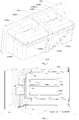
Fig. 1 is a partial schematic view of an air-cooled refrigerator according to embodiments of the present disclosure; -
Fig. 2 is a schematic view of an electrical damper of an air-cooled refrigerator according to embodiments of the present disclosure; -
Fig. 3 is a partial sectional view of an air-cooled refrigerator according to embodiments of the present disclosure; -
Fig. 4 is a partial sectional view of an air-cooled refrigerator according to embodiments of the present disclosure. - Embodiments of the present disclosure will be described in detail in the following. Examples of the embodiments are illustrated in the drawings. The embodiments described herein with reference to drawings are explanatory, which are intended to explain the present disclosure, and shall not be construed to limit the present disclosure.
- The present disclosure is made based on discoveries and acknowledges of the following facts and problems by inventors: a dual electrical damper of an existing three-door air-cooled refrigerator, i.e. an air-cooled refrigerator having a freezing compartment, a refrigerating compartment and a temperature-variable compartment, tends to be involved in a control failure, causing the refrigerating compartment and the temperature-variable compartment to be unable to perform refrigeration. It is found after in-depth research by the inventors that, because the dual electrical damper is mounted in the freezing compartment and temperature in the freezing compartment is relatively low, the dual electrical damper tends to frost and ice up, thereby leading the dual electrical damper to a control failure much easily.
- An air-cooled
refrigerator 10 according to embodiments of the present disclosure will be described with reference to the drawings in the following. As shown inFigs. 1-4 , the air-cooledrefrigerator 10 according to embodiments of the present disclosure includes ahousing 101, a freezinginner container 1021, a temperature-variableinner container 1022, a refrigeratinginner container 1023, afoaming layer 103, an embeddedmember 104, anelectrical damper 105, a freezing air-outlet passage 1061, a temperature-variable air-inlet passage 1062, and a refrigerating air-inlet passage (not shown in the drawings). - The freezing
inner container 1021, the temperature-variableinner container 1022 and the refrigeratinginner container 1023 are disposed in thehousing 101 at intervals in an up and down direction, a wall of the temperature-variableinner container 1022 is provided with a temperature-variable air inlet, a wall of the refrigeratinginner container 1023 is provided with a refrigerating air inlet, and a wall of the freezinginner container 1021 is provided with an air outlet. Thefoaming layer 103 is filled in a space between thehousing 101 and the freezinginner container 1021, the temperature-variableinner container 1022 and the refrigeratinginner container 1023. The embeddedmember 104 is disposed in thefoaming layer 103, theelectrical damper 105 is provided to the embeddedmember 104, theelectrical damper 105 is located in thefoaming layer 103, theelectrical damper 105 is provided with a cold air inlet (not shown in the drawings) and a firstcold air outlet 1053 and a secondcold air outlet 1054 in communication with the cold air inlet. In other words, theelectrical damper 105 is a dual electrical damper. - A first end of the freezing air-
outlet passage 1061 is connected with the air outlet of the freezinginner container 1021, and a second end of the freezing air-outlet passage 1061 is connected with the cold air inlet of theelectrical damper 105. A first end of the temperature-variable air-inlet passage 1062 is connected with the firstcold air outlet 1053, and a second end of the temperature-variable air-inlet passage 1062 is connected with the temperature-variable air inlet of the temperature-variableinner container 1022. A first end of the refrigerating air-inlet passage is connected with the secondcold air outlet 1054, and a second end of the refrigerating air-inlet passage is connected with the refrigerating air inlet of the refrigeratinginner container 1023. - In the air-cooled
refrigerator 10 according to embodiments of the present disclosure, by mounting theelectrical damper 105 to the embeddedmember 104 located in thefoaming layer 103, theelectrical damper 105 can be mounted in thefoaming layer 103, therefore it is possible to prevent theelectrical damper 105 from being in a low temperature environment, thereby avoiding theelectrical damper 105 from being involved in a control failure due to frosting and icing, so as to effectively perform refrigeration in a space of the temperature-variableinner container 1022 and the refrigeratinginner container 1023, i.e., effectively performing refrigeration in the refrigerating compartment and the temperature-variable compartment. - Moreover, since the
electrical damper 105 is no longer mounted in the freezinginner container 1021, i.e., theelectrical damper 105 is no longer mounted in the freezing compartment, a storage space in the freezinginner container 1021 can be increased. Furthermore, theelectrical damper 105 is mounted in the embeddedmember 104, such that theelectrical damper 105 can be mounted more easily and steadily. - Therefore, the
electrical damper 105 of the air-cooledrefrigerator 10 according to embodiments of the present disclosure doesn't tend to be involved in the control failure, and the air-cooledrefrigerator 10 has advantages of a large storage space, a reasonable structure and the like. - It could be understood by those skilled in the art that, the refrigerating
inner container 1023 can be provided with a refrigerating return air inlet, the temperature-variableinner container 1022 can be provided with a temperature-variable return air inlet, and the freezinginner container 1021 can be provided with a freezing return air inlet in communication with the refrigerating return air inlet and the temperature-variable return air inlet. These structures can be known and can be independent from inventive concepts of the present disclosure, and thus will not be elaborated. - As shown in
Figs. 1-4 , in some embodiments of the present disclosure, the air-cooledrefrigerator 10 includes thehousing 101, the freezinginner container 1021, the temperature-variableinner container 1022, the refrigeratinginner container 1023, thefoaming layer 103, the embeddedmember 104, theelectrical damper 105, the freezing air-outlet passage 1061, the temperature-variable air-inlet passage 1062, and the refrigerating air-inlet passage (not shown in the drawings). - The temperature-variable
inner container 1022 is disposed above the freezinginner container 1021, and the refrigeratinginner container 1023 is disposed above the temperature-variableinner container 1022. The freezinginner container 1021 has the freezing compartment therein, the temperature-variableinner container 1022 has the temperature-variable compartment therein, and the refrigeratinginner container 1023 has the refrigerating compartment therein. The up and down direction is shown by an arrow C inFig. 1 . - The
foaming layer 103 is filled in the space between thehousing 101 and the freezinginner container 1021, the temperature-variableinner container 1022 and the refrigeratinginner container 1023. The embeddedmember 104 is disposed in thefoaming layer 103, theelectrical damper 105 is provided to the embeddedmember 104, and that is, theelectrical damper 105 is also disposed in thefoaming layer 103. - As shown in
Figs. 3 and4 , in an embodiment of the present disclosure, the embeddedmember 104 and theelectrical damper 105 are opposite to the temperature-variableinner container 1022 or the refrigeratinginner container 1023 in a horizontal direction. Thus it is possible to further prevent theelectrical damper 105 from being in the low temperature environment, thereby further avoiding theelectrical damper 105 from being involved in the control failure due to frosting and icing, so as to more effectively perform refrigeration in the space of the temperature-variableinner container 1022 and the refrigeratinginner container 1023, i.e., effectively performing refrigeration in the refrigerating compartment and the temperature-variable compartment. - Advantageously, the embedded
member 104 and theelectrical damper 105 are opposite to the temperature-variableinner container 1022 in the horizontal direction. Since the temperature-variableinner container 1022 is located below the refrigeratinginner container 1023, by allowing theelectrical damper 105 to be opposite to the temperature-variableinner container 1022 in the horizontal direction, the cold air flowing away from the freezinginner container 1021 can be allowed to just flow in a single direction from down to up. - More advantageously, the embedded
member 104 and theelectrical damper 105 are disposed at rear of the temperature-variableinner container 1022, a rear direction can be a direction away from a user, and a front direction can be a direction adjacent to the user, front and rear directions are shown by an arrow A inFigs. 3 and4 . - As shown in
Fig. 2 , in some examples of the present disclosure, theelectrical damper 105 includes abody 1051 and a separating member (not shown in the drawings). Thebody 1051 has acavity 1052 therein, and a bottom wall of thecavity 1052 is provided with the cold air inlet. The separating member is disposed in thecavity 1052, and the separating member divides thecavity 1052 into a first sub-cavity and a second sub-cavity and divides the cold air inlet into a first cold air sub-inlet communicated with the first sub-cavity and a second cold air sub-inlet communicated with the second sub-cavity. A top wall of the first sub-cavity is provided with a firstcold air outlet 1053, and a top wall of the second sub-cavity is provided with a secondcold air outlet 1054. - In other words, the cold air entering the
cavity 1052 of theelectrical damper 105 through the cold air inlet is divided into two parts by the separating member, a first part flows in the first sub-cavity and enters the temperature-variable air-inlet passage 1062 through the firstcold air outlet 1053, and a second part flows in the second sub-cavity and enters the refrigerating air-inlet passage through the secondcold air outlet 1054, thus allowing the structure of theelectrical damper 105 to be more reasonable. - As shown in
Fig. 1 , the embeddedmember 104 has a mountingcavity 1041 having an open end, and at least a part of theelectrical damper 105 is disposed in the mountingcavity 1041, thus allowing the structure of the air-cooledrefrigerator 10 to be more reasonable. Specifically, a front end of the mountingcavity 1041 is open. - Since at least the part of the
electrical damper 105 is disposed in the mountingcavity 1041, the second end of the freezing air-outlet passage 1061 is connected with the cold air inlet of theelectrical damper 105 by penetrating the embeddedmember 104 or through a through hole in the embeddedmember 104, the first end of the temperature-variable air-inlet passage 1062 is connected with the firstcold air outlet 1053 by penetrating the embeddedmember 104 or through the through hole in the embeddedmember 104, and the first end of the refrigerating air-inlet passage is connected with the secondcold air outlet 1054 by penetrating the embeddedmember 104 or through the through hole in the embeddedmember 104. - In related art, in order to prevent air leakage, the air inlet and air outlet of the electrical damper are sealed by a sponge, that is, the sponge is pasted at the air inlet and air outlet of the electrical damper. However, the fact that the air inlet and air outlet of the electrical damper are sealed by the sponge enables the assembly processing to be complicated and increases the assembly difficulty, moreover, the sponge tends to curl up, influencing the sealing effect. Specifically, in the air-cooled
refrigerator 10 according to embodiments of the present disclosure, since at least the part of theelectrical damper 105 is disposed in the embeddedmember 104, that is, the cold air inlet, the firstcold air outlet 1053 and the secondcold air outlet 1054 of theelectrical damper 105 are located in the mountingcavity 1041 of the embeddedmember 104, if the sponge is pasted at the cold air inlet, the firstcold air outlet 1053 and the secondcold air outlet 1054 of theelectrical damper 105, the sponge must penetrate the embeddedmember 104, which further increases the assembly difficulty, enables the assembly processing to be more complicated and the sponge to curl up more easily. - In an example of the present disclosure, as shown in
Figs. 1-4 , a wall of the mountingcavity 1041 is provided with ahorizontal groove 1042 and avertical groove 1043, and an outer surface of theelectrical damper 105 is provided with a horizontalconvex rib 1055 and a verticalconvex rib 1056. At least a part of the horizontalconvex rib 1055 is disposed in thehorizontal groove 1042, and at least a part of the verticalconvex rib 1056 is disposed in thevertical groove 1043. - Thus the
electrical damper 105 can be mounted in the mountingcavity 1041 of the embeddedmember 104 more conveniently and steadily, moreover, by fitting the horizontalconvex rib 1055 to thehorizontal groove 1042, the cold air output from the freezinginner container 1021 can be prevented from leaking in the up and down direction, and by fitting the verticalconvex rib 1056 into thevertical groove 1043, the cold air output from the freezinginner container 1021 can be prevented from leaking in a left and right direction. That is, for the air-cooledrefrigerator 10 according to embodiments of the present disclosure, it is not necessary to paste the sponge at the cold air inlet, the firstcold air outlet 1053 and the secondcold air outlet 1054 of theelectrical damper 105, thereby simplifying the assembly processing, reducing the assembly difficulty and improving the sealing effect. - Advantageously, a shape of the horizontal
convex rib 1055 is adapted to a shape of thehorizontal groove 1042, and a shape of the verticalconvex rib 1056 is adapted to a shape of thevertical groove 1043. Thus, theelectrical damper 105 can be mounted in the mountingcavity 1041 of the embeddedmember 104 more conveniently and steadily, moreover, the sealing effect for theelectrical damper 105 can be further improved. - As shown in
Figs. 1-4 , in a specific example of the present disclosure, thehorizontal groove 1042 includes afirst sub-groove 10421 disposed to a first side wall (e.g. a left side wall) of the mountingcavity 1041, asecond sub-groove 10422 disposed to a second side wall (e.g. a right side wall) of the mountingcavity 1041, and a third sub-groove 10423 disposed to a rear wall of the mountingcavity 1041. A first end (e.g. a left end) of thethird sub-groove 10423 is connected with an end (e.g. a rear end) of thefirst sub-groove 10421, and a second end (e.g. a right end) of thethird sub-groove 10423 is connected with an end (e.g. a rear end) of thesecond sub-groove 10422. Thevertical groove 1043 is disposed in the rear wall of the mountingcavity 1041, and thevertical groove 1043 intersects with the third sub-groove 10423 to form a cross. - The horizontal
convex rib 1055 includes a firstconvex sub-rib 10551 disposed to a first side face (e.g. a left side face) of theelectrical damper 105 and fitted in thefirst sub-groove 10421, a secondconvex sub-rib 10552 disposed to a second side face (e.g. a right side face) of theelectrical damper 105 and fitted in thesecond sub-groove 10422, and a thirdconvex sub-rib 10553 disposed to a rear surface of theelectrical damper 105 and fitted in thethird sub-groove 10423. A first end (e.g. a left end) of the thirdconvex sub-rib 10553 is connected with an end (e.g. a rear end) of the firstconvex sub-rib 10551, and a second end (e.g. a right end) of the thirdconvex sub-rib 10553 is connected with an end (e.g. a rear end) of the secondconvex sub-rib 10552. The verticalconvex rib 1056 is disposed to the rear surface of theelectrical damper 105 and the verticalconvex rib 1056 intersects with the thirdconvex sub-rib 10553 to form a cross. - Thus, the
electrical damper 105 can be mounted in the mountingcavity 1041 of the embeddedmember 104 more conveniently and steadily, moreover, the sealing effect for theelectrical damper 105 can be further improved. The left and right direction is shown by an arrow B inFig. 1 . - Advantageously, a top wall of the mounting
cavity 1041 is provided with anupper groove 1044, a bottom wall of the mountingcavity 1041 is provided with alower groove 1045, an upper surface of theelectrical damper 105 is provided with an upperconvex rib 1057, and a lower surface of theelectrical damper 105 is provided with a lower convex rib (not shown in the drawings). An upper end of thevertical groove 1043 is connected with a rear end of theupper groove 1044, and a lower end of thevertical groove 1043 is connected with a rear end of thelower groove 1045, an upper end of the verticalconvex rib 1056 is connected with a rear end of the upperconvex rib 1057 and a lower end of the verticalconvex rib 1056 is connected with a rear end of the lower convex rib. At least a part of the upperconvex rib 1057 is disposed in theupper groove 1044, and at least a part of the lower convex rib is disposed in thelower groove 1045. Thus theelectrical damper 105 can be mounted in the mountingcavity 1041 of the embeddedmember 104 more conveniently and steadily, moreover, the cold air output from the freezinginner container 1021 can be further prevented from leaking in the left and right direction. - As shown in
Figs. 2 and4 , the air-cooledrefrigerator 10 further includes anannular sponge piece 107, thesponge piece 107 is disposed to a front surface and/or an outercircumferential surface 1058 of theelectrical damper 105, and thesponge piece 107 abuts against thefoaming layer 103. In other words, thesponge piece 107 can be disposed to the front surface of theelectrical damper 105, can also be disposed to the outercircumferential surface 1058 of theelectrical damper 105, and can further be disposed to both of the front surface and the outercircumferential surface 1058 of theelectrical damper 105. Thus, the sealing effect for theelectrical damper 105 can further be improved. - Advantageously, a front part of the outer
circumferential surface 1058 of theelectrical damper 105 and/or the front surface of theelectrical damper 105 are (is) provided with anannular flange 108, and thesponge piece 107 is disposed to theflange 108. That is, theflange 108 can be disposed to the front surface of theelectrical damper 105, can also be disposed to the outercircumferential surface 1058 of theelectrical damper 105, and can further be disposed to both of the front surface of theelectrical damper 105 and the outercircumferential surface 1058 of theelectrical damper 105. Thus, thesponge piece 107 can be mounted more conveniently and steadily. - In the specification, it is to be understood that terms such as "central," "longitudinal," "lateral," "length," "width," "thickness," "upper," "lower," "front," "rear," "left," "right," "vertical," "horizontal," "top," "bottom," "inner," "outer," "axial," "radial," "circumferential direction," "clockwise," and "counterclockwise" should be construed to refer to the orientation as then described or as shown in the drawings under discussion. These relative terms are for convenience of description and do not require that the present invention be constructed or operated in a particular orientation.
- In addition, terms such as "first" and "second" are used herein for purposes of description and are not intended to indicate or imply relative importance or significance or to imply the number of indicated technical features. Thus, the feature defined with "first" and "second" may comprise one or more of this feature. In the description of the present invention, "a plurality of' means two or more than two, unless specified otherwise.
- In the present invention, unless specified or limited otherwise, the terms "mounted," "connected," "coupled," "fixed" and the like are used broadly, and may be, for example, fixed connections, detachable connections, or integral connections; may also be mechanical or electrical connections; may also be direct connections or indirect connections via intervening structures; may also be inner communications of two elements, which can be understood by those skilled in the art according to specific situations.
- In the present invention, unless specified or limited otherwise, a structure in which a first feature is "on" or "below" a second feature may include an embodiment in which the first feature is in direct contact with the second feature, and may also include an embodiment in which the first feature and the second feature are not in direct contact with each other, but are contacted via an additional feature formed therebetween. Furthermore, a first feature "on," "above," or "on top of' a second feature may include an embodiment in which the first feature is right or obliquely "on," "above," or "on top of' the second feature, or just means that the first feature is at a height higher than that of the second feature; while a first feature "below," "under," or "on bottom of' a second feature may include an embodiment in which the first feature is right or obliquely "below," "under," or "on bottom of' the second feature, or just means that the first feature is at a height lower than that of the second feature.
- Reference throughout this specification to "an embodiment," "some embodiments," "one embodiment", "another example," "an example," "a specific example," or "some examples," means that a particular feature, structure, material, or characteristic described in connection with the embodiment or example is included in at least one embodiment or example of the present disclosure. Thus, the appearances of the phrases such as "in some embodiments," "in one embodiment", "in an embodiment", "in another example," "in an example," "in a specific example," or "in some examples," in various places throughout this specification are not necessarily referring to the same embodiment or example of the present disclosure. Furthermore, the particular features, structures, materials, or characteristics may be combined in any suitable manner in one or more embodiments or examples.
- Although explanatory embodiments have been shown and described, it would be appreciated by those skilled in the art that the above embodiments cannot be construed to limit the present disclosure, and changes, alternatives, and modifications can be made in the embodiments without departing from the scope of the present disclosure.
Claims (10)
- An air-cooled refrigerator, comprising:a housing;a freezing inner container, a temperature-variable inner container and a refrigerating inner container disposed in the housing at intervals in an up and down direction, wherein a wall of the temperature-variable inner container is provided with a temperature-variable air inlet, a wall of the refrigerating inner container is provided with a refrigerating air inlet, and a wall of the freezing inner container is provided with an air outlet;a foaming layer filled in a space between the housing and the freezing inner container, the temperature-variable inner container and the refrigerating inner container;an embedded member disposed in the foaming layer;an electrical damper provided to the embedded member and located in the foaming layer, the electrical damper being provided with a cold air inlet and a first cold air outlet and a second cold air outlet in communication with the cold air inlet;a freezing air-outlet passage having a first end connected with the air outlet and a second end connected with the cold air inlet; anda temperature-variable air-inlet passage and a refrigerating air-inlet passage, the temperature-variable air-inlet passage having a first end connected with the first cold air outlet and a second end connected with the temperature-variable air inlet, the refrigerating air-inlet passage having a first end connected with the second cold air outlet and a second end connected with the refrigerating air inlet.
- The air-cooled refrigerator according to claim 1, wherein the embedded member and the electrical damper are opposite to the temperature-variable inner container or the refrigerating inner container in a horizontal direction.
- The air-cooled refrigerator according to claim 1, wherein the embedded member has a mounting cavity, the mounting cavity having an open end, and at least a part of the electrical damper is disposed in the mounting cavity.
- The air-cooled refrigerator according to claim 3, wherein a wall of the mounting cavity is provided with a horizontal groove and a vertical groove, and an outer surface of the electrical damper is provided with a horizontal convex rib and a vertical convex rib, wherein at least a part of the horizontal convex rib is disposed in the horizontal groove, and at least a part of the vertical convex rib is disposed in the vertical groove.
- The air-cooled refrigerator according to claim 4, wherein a shape of the horizontal convex rib is adapted to a shape of the horizontal groove, and a shape of the vertical convex rib is adapted to a shape of the vertical groove.
- The air-cooled refrigerator according to claim 5, wherein the horizontal groove comprises a first sub-groove disposed to a first side wall of the mounting cavity, a second sub-groove disposed to a second side wall of the mounting cavity, and a third sub-groove disposed to a rear wall of the mounting cavity, the third sub-groove having a first end connected with an end of the first sub-groove and a second end connected with an end of the second sub-groove, wherein the vertical groove is disposed in the rear wall of the mounting cavity, and the vertical groove intersects with the third sub-groove to form a cross;
the horizontal convex rib comprises a first convex sub-rib disposed to a first side face of the electrical damper and fitted in the first sub-groove, a second convex sub-rib disposed to a second side face of the electrical damper and fitted in the second sub-groove, and a third convex sub-rib disposed to a rear surface of the electrical damper and fitted in the third sub-groove, the third convex sub-rib having a first end connected with an end of the first convex sub-rib and a second end connected with an end of the second convex sub-rib, wherein the vertical convex rib is disposed to the rear surface of the electrical damper and the vertical convex rib intersects with the third convex sub-rib to form a cross. - The air-cooled refrigerator according to claim 6, wherein a top wall of the mounting cavity is provided with an upper groove, a bottom wall of the mounting cavity is provided with a lower groove, an upper surface of the electrical damper is provided with an upper convex rib, and a lower surface of the electrical damper is provided with a lower convex rib, wherein the vertical groove has an upper end connected with a rear end of the upper groove and a lower end connected with a rear end of the lower groove, the vertical convex rib has an upper end connected with a rear end of the upper convex rib and a lower end connected with a rear end of the lower convex rib, at least a part of the upper convex rib is disposed in the upper groove, and at least a part of the lower convex rib is disposed in the lower groove.
- The air-cooled refrigerator according to claim 1, wherein the electrical damper comprises:a body, the body having a cavity therein, and a bottom wall of the cavity being provided with the cold air inlet; anda separating member disposed in the cavity, the separating member dividing the cavity into a first sub-cavity and a second sub-cavity and dividing the cold air inlet into a first cold air sub-inlet communicated with the first sub-cavity and a second cold air sub-inlet communicated with the second sub-cavity, wherein a top wall of the first sub-cavity is provided with a first cold air outlet, and a top wall of the second sub-cavity is provided with a second cold air outlet.
- The air-cooled refrigerator according to any one of claims 1-8, wherein the air-cooled refrigerator further comprises an annular sponge piece, the sponge piece being disposed to a front surface and/or an outer circumferential surface of the electrical damper, the sponge piece abutting against the foaming layer.
- The air-cooled refrigerator according to claim 9, wherein a front part of the outer circumferential surface of the electrical damper and/or the front surface of the electrical damper are provided with an annular flange, and the sponge piece is disposed to the flange.
Applications Claiming Priority (3)
| Application Number | Priority Date | Filing Date | Title |
|---|---|---|---|
| CN201520684164.0U CN205048849U (en) | 2015-09-06 | 2015-09-06 | Air -cooling refrigerator |
| CN201510560960.8A CN105042990A (en) | 2015-09-06 | 2015-09-06 | Air-cooled refrigerator |
| PCT/CN2015/089454 WO2017035867A1 (en) | 2015-09-06 | 2015-09-11 | Air-cooled refrigerator |
Publications (3)
| Publication Number | Publication Date |
|---|---|
| EP3346212A1 true EP3346212A1 (en) | 2018-07-11 |
| EP3346212A4 EP3346212A4 (en) | 2018-09-05 |
| EP3346212B1 EP3346212B1 (en) | 2020-03-18 |
Family
ID=58186581
Family Applications (1)
| Application Number | Title | Priority Date | Filing Date |
|---|---|---|---|
| EP15902674.9A Active EP3346212B1 (en) | 2015-09-06 | 2015-09-11 | Air-cooled refrigerator |
Country Status (5)
| Country | Link |
|---|---|
| US (1) | US10508855B2 (en) |
| EP (1) | EP3346212B1 (en) |
| ES (1) | ES2791955T3 (en) |
| PT (1) | PT3346212T (en) |
| WO (1) | WO2017035867A1 (en) |
Family Cites Families (16)
| Publication number | Priority date | Publication date | Assignee | Title |
|---|---|---|---|---|
| US3104533A (en) * | 1961-04-24 | 1963-09-24 | Gen Motors Corp | Refrigerating apparatus |
| JPS60135591U (en) * | 1984-02-20 | 1985-09-09 | 三菱電機株式会社 | Refrigerator air duct structure |
| JPH0788997B2 (en) * | 1988-08-09 | 1995-09-27 | 株式会社東芝 | refrigerator |
| JP2001263908A (en) * | 2000-03-17 | 2001-09-26 | Fujitsu General Ltd | refrigerator |
| US20060168990A1 (en) * | 2005-02-01 | 2006-08-03 | Jung-Bum Park | Damper device for refrigerator |
| EP2144023A4 (en) * | 2007-04-26 | 2012-08-08 | Panasonic Corp | FRIDGE |
| KR20110072370A (en) * | 2009-12-22 | 2011-06-29 | 엘지전자 주식회사 | Refrigerator |
| CN102564007B (en) * | 2012-03-09 | 2014-05-21 | 合肥美的电冰箱有限公司 | refrigerator |
| CN102788465A (en) * | 2012-07-18 | 2012-11-21 | 合肥华凌股份有限公司 | Refrigerator |
| CN203224089U (en) | 2013-03-18 | 2013-10-02 | 合肥晶弘电器有限公司 | Variable temperature air door installation structure |
| CN203771864U (en) | 2014-04-09 | 2014-08-13 | 合肥美的电冰箱有限公司 | Air duct system for refrigerator and refrigerator with air duct system |
| CN104006617B (en) * | 2014-06-13 | 2017-01-04 | 合肥华凌股份有限公司 | Refrigerator |
| US10001316B2 (en) * | 2014-09-25 | 2018-06-19 | Electrolux Home Products, Inc. | Freezer air tower and damper |
| CN204202275U (en) * | 2014-09-30 | 2015-03-11 | 青岛海尔股份有限公司 | Refrigerator |
| CN104567180A (en) * | 2014-12-26 | 2015-04-29 | 海信容声(广东)冰箱有限公司 | Air-cooled refrigerator |
| CN205048849U (en) | 2015-09-06 | 2016-02-24 | 合肥美的电冰箱有限公司 | Air -cooling refrigerator |
-
2015
- 2015-09-11 EP EP15902674.9A patent/EP3346212B1/en active Active
- 2015-09-11 ES ES15902674T patent/ES2791955T3/en active Active
- 2015-09-11 PT PT159026749T patent/PT3346212T/en unknown
- 2015-09-11 WO PCT/CN2015/089454 patent/WO2017035867A1/en not_active Ceased
- 2015-09-11 US US15/757,654 patent/US10508855B2/en active Active
Also Published As
| Publication number | Publication date |
|---|---|
| EP3346212B1 (en) | 2020-03-18 |
| US10508855B2 (en) | 2019-12-17 |
| EP3346212A4 (en) | 2018-09-05 |
| US20180245834A1 (en) | 2018-08-30 |
| WO2017035867A1 (en) | 2017-03-09 |
| PT3346212T (en) | 2020-06-22 |
| ES2791955T3 (en) | 2020-11-06 |
Similar Documents
| Publication | Publication Date | Title |
|---|---|---|
| US9441779B1 (en) | Split hybrid insulation structure for an appliance | |
| CN107246754B (en) | An air-cooled horizontal freezer | |
| US10712076B2 (en) | Air-cooled refrigerator | |
| EP3006869B1 (en) | Refrigeration device | |
| US20200393187A1 (en) | Ice maker-integrated refrigerator | |
| CN109696010B (en) | Refrigeration air supply assembly and side-by-side refrigerator | |
| US10655906B2 (en) | Refrigerator | |
| CN105865128B (en) | A kind of refrigerator supply air system, method and refrigerator | |
| EP3751221A1 (en) | Refrigeration air supply assembly | |
| EP2787312A1 (en) | Refrigerator | |
| CN104990341A (en) | Refrigerator | |
| CN105318632A (en) | refrigerator | |
| CN205425588U (en) | Refrigerator with a door | |
| CN105042990A (en) | Air-cooled refrigerator | |
| US10508855B2 (en) | Refrigerator | |
| CN205048849U (en) | Air -cooling refrigerator | |
| CN103017446B (en) | Air-cooled refrigerator | |
| CN104976851A (en) | Refrigerator | |
| EP2765373B1 (en) | Shroud for refrigerator | |
| JP6398073B2 (en) | refrigerator | |
| US11561039B2 (en) | Sealing assembly having improved heat insulation properties and cooling device having the sealing assembly | |
| CN204880929U (en) | Refrigerator | |
| CN204187907U (en) | Refrigerator and the interface channel for this refrigerator | |
| CN210320813U (en) | Door seal with foaming structure | |
| CN204100686U (en) | Cold storage |
Legal Events
| Date | Code | Title | Description |
|---|---|---|---|
| STAA | Information on the status of an ep patent application or granted ep patent |
Free format text: STATUS: THE INTERNATIONAL PUBLICATION HAS BEEN MADE |
|
| PUAI | Public reference made under article 153(3) epc to a published international application that has entered the european phase |
Free format text: ORIGINAL CODE: 0009012 |
|
| STAA | Information on the status of an ep patent application or granted ep patent |
Free format text: STATUS: REQUEST FOR EXAMINATION WAS MADE |
|
| 17P | Request for examination filed |
Effective date: 20180321 |
|
| AK | Designated contracting states |
Kind code of ref document: A1 Designated state(s): AL AT BE BG CH CY CZ DE DK EE ES FI FR GB GR HR HU IE IS IT LI LT LU LV MC MK MT NL NO PL PT RO RS SE SI SK SM TR |
|
| AX | Request for extension of the european patent |
Extension state: BA ME |
|
| A4 | Supplementary search report drawn up and despatched |
Effective date: 20180803 |
|
| RIC1 | Information provided on ipc code assigned before grant |
Ipc: F25D 11/02 20060101ALI20180730BHEP Ipc: F25D 17/06 20060101ALI20180730BHEP Ipc: F25D 17/04 20060101AFI20180730BHEP |
|
| DAV | Request for validation of the european patent (deleted) | ||
| DAX | Request for extension of the european patent (deleted) | ||
| GRAP | Despatch of communication of intention to grant a patent |
Free format text: ORIGINAL CODE: EPIDOSNIGR1 |
|
| STAA | Information on the status of an ep patent application or granted ep patent |
Free format text: STATUS: GRANT OF PATENT IS INTENDED |
|
| INTG | Intention to grant announced |
Effective date: 20190925 |
|
| GRAS | Grant fee paid |
Free format text: ORIGINAL CODE: EPIDOSNIGR3 |
|
| GRAA | (expected) grant |
Free format text: ORIGINAL CODE: 0009210 |
|
| STAA | Information on the status of an ep patent application or granted ep patent |
Free format text: STATUS: THE PATENT HAS BEEN GRANTED |
|
| AK | Designated contracting states |
Kind code of ref document: B1 Designated state(s): AL AT BE BG CH CY CZ DE DK EE ES FI FR GB GR HR HU IE IS IT LI LT LU LV MC MK MT NL NO PL PT RO RS SE SI SK SM TR |
|
| REG | Reference to a national code |
Ref country code: GB Ref legal event code: FG4D |
|
| REG | Reference to a national code |
Ref country code: DE Ref legal event code: R096 Ref document number: 602015049233 Country of ref document: DE |
|
| REG | Reference to a national code |
Ref country code: AT Ref legal event code: REF Ref document number: 1246364 Country of ref document: AT Kind code of ref document: T Effective date: 20200415 Ref country code: IE Ref legal event code: FG4D |
|
| REG | Reference to a national code |
Ref country code: PT Ref legal event code: SC4A Ref document number: 3346212 Country of ref document: PT Date of ref document: 20200622 Kind code of ref document: T Free format text: AVAILABILITY OF NATIONAL TRANSLATION Effective date: 20200615 |
|
| PG25 | Lapsed in a contracting state [announced via postgrant information from national office to epo] |
Ref country code: NO Free format text: LAPSE BECAUSE OF FAILURE TO SUBMIT A TRANSLATION OF THE DESCRIPTION OR TO PAY THE FEE WITHIN THE PRESCRIBED TIME-LIMIT Effective date: 20200618 Ref country code: FI Free format text: LAPSE BECAUSE OF FAILURE TO SUBMIT A TRANSLATION OF THE DESCRIPTION OR TO PAY THE FEE WITHIN THE PRESCRIBED TIME-LIMIT Effective date: 20200318 Ref country code: RS Free format text: LAPSE BECAUSE OF FAILURE TO SUBMIT A TRANSLATION OF THE DESCRIPTION OR TO PAY THE FEE WITHIN THE PRESCRIBED TIME-LIMIT Effective date: 20200318 |
|
| REG | Reference to a national code |
Ref country code: NL Ref legal event code: MP Effective date: 20200318 |
|
| PG25 | Lapsed in a contracting state [announced via postgrant information from national office to epo] |
Ref country code: HR Free format text: LAPSE BECAUSE OF FAILURE TO SUBMIT A TRANSLATION OF THE DESCRIPTION OR TO PAY THE FEE WITHIN THE PRESCRIBED TIME-LIMIT Effective date: 20200318 Ref country code: SE Free format text: LAPSE BECAUSE OF FAILURE TO SUBMIT A TRANSLATION OF THE DESCRIPTION OR TO PAY THE FEE WITHIN THE PRESCRIBED TIME-LIMIT Effective date: 20200318 Ref country code: LV Free format text: LAPSE BECAUSE OF FAILURE TO SUBMIT A TRANSLATION OF THE DESCRIPTION OR TO PAY THE FEE WITHIN THE PRESCRIBED TIME-LIMIT Effective date: 20200318 Ref country code: GR Free format text: LAPSE BECAUSE OF FAILURE TO SUBMIT A TRANSLATION OF THE DESCRIPTION OR TO PAY THE FEE WITHIN THE PRESCRIBED TIME-LIMIT Effective date: 20200619 Ref country code: BG Free format text: LAPSE BECAUSE OF FAILURE TO SUBMIT A TRANSLATION OF THE DESCRIPTION OR TO PAY THE FEE WITHIN THE PRESCRIBED TIME-LIMIT Effective date: 20200618 |
|
| REG | Reference to a national code |
Ref country code: LT Ref legal event code: MG4D |
|
| PG25 | Lapsed in a contracting state [announced via postgrant information from national office to epo] |
Ref country code: NL Free format text: LAPSE BECAUSE OF FAILURE TO SUBMIT A TRANSLATION OF THE DESCRIPTION OR TO PAY THE FEE WITHIN THE PRESCRIBED TIME-LIMIT Effective date: 20200318 |
|
| PG25 | Lapsed in a contracting state [announced via postgrant information from national office to epo] |
Ref country code: CZ Free format text: LAPSE BECAUSE OF FAILURE TO SUBMIT A TRANSLATION OF THE DESCRIPTION OR TO PAY THE FEE WITHIN THE PRESCRIBED TIME-LIMIT Effective date: 20200318 Ref country code: SM Free format text: LAPSE BECAUSE OF FAILURE TO SUBMIT A TRANSLATION OF THE DESCRIPTION OR TO PAY THE FEE WITHIN THE PRESCRIBED TIME-LIMIT Effective date: 20200318 Ref country code: RO Free format text: LAPSE BECAUSE OF FAILURE TO SUBMIT A TRANSLATION OF THE DESCRIPTION OR TO PAY THE FEE WITHIN THE PRESCRIBED TIME-LIMIT Effective date: 20200318 Ref country code: EE Free format text: LAPSE BECAUSE OF FAILURE TO SUBMIT A TRANSLATION OF THE DESCRIPTION OR TO PAY THE FEE WITHIN THE PRESCRIBED TIME-LIMIT Effective date: 20200318 Ref country code: LT Free format text: LAPSE BECAUSE OF FAILURE TO SUBMIT A TRANSLATION OF THE DESCRIPTION OR TO PAY THE FEE WITHIN THE PRESCRIBED TIME-LIMIT Effective date: 20200318 Ref country code: IS Free format text: LAPSE BECAUSE OF FAILURE TO SUBMIT A TRANSLATION OF THE DESCRIPTION OR TO PAY THE FEE WITHIN THE PRESCRIBED TIME-LIMIT Effective date: 20200718 Ref country code: SK Free format text: LAPSE BECAUSE OF FAILURE TO SUBMIT A TRANSLATION OF THE DESCRIPTION OR TO PAY THE FEE WITHIN THE PRESCRIBED TIME-LIMIT Effective date: 20200318 |
|
| REG | Reference to a national code |
Ref country code: ES Ref legal event code: FG2A Ref document number: 2791955 Country of ref document: ES Kind code of ref document: T3 Effective date: 20201106 |
|
| REG | Reference to a national code |
Ref country code: AT Ref legal event code: MK05 Ref document number: 1246364 Country of ref document: AT Kind code of ref document: T Effective date: 20200318 |
|
| REG | Reference to a national code |
Ref country code: DE Ref legal event code: R097 Ref document number: 602015049233 Country of ref document: DE |
|
| PLBE | No opposition filed within time limit |
Free format text: ORIGINAL CODE: 0009261 |
|
| STAA | Information on the status of an ep patent application or granted ep patent |
Free format text: STATUS: NO OPPOSITION FILED WITHIN TIME LIMIT |
|
| PG25 | Lapsed in a contracting state [announced via postgrant information from national office to epo] |
Ref country code: DK Free format text: LAPSE BECAUSE OF FAILURE TO SUBMIT A TRANSLATION OF THE DESCRIPTION OR TO PAY THE FEE WITHIN THE PRESCRIBED TIME-LIMIT Effective date: 20200318 Ref country code: AT Free format text: LAPSE BECAUSE OF FAILURE TO SUBMIT A TRANSLATION OF THE DESCRIPTION OR TO PAY THE FEE WITHIN THE PRESCRIBED TIME-LIMIT Effective date: 20200318 |
|
| 26N | No opposition filed |
Effective date: 20201221 |
|
| PG25 | Lapsed in a contracting state [announced via postgrant information from national office to epo] |
Ref country code: PL Free format text: LAPSE BECAUSE OF FAILURE TO SUBMIT A TRANSLATION OF THE DESCRIPTION OR TO PAY THE FEE WITHIN THE PRESCRIBED TIME-LIMIT Effective date: 20200318 |
|
| REG | Reference to a national code |
Ref country code: CH Ref legal event code: PL |
|
| PG25 | Lapsed in a contracting state [announced via postgrant information from national office to epo] |
Ref country code: SI Free format text: LAPSE BECAUSE OF FAILURE TO SUBMIT A TRANSLATION OF THE DESCRIPTION OR TO PAY THE FEE WITHIN THE PRESCRIBED TIME-LIMIT Effective date: 20200318 |
|
| REG | Reference to a national code |
Ref country code: BE Ref legal event code: MM Effective date: 20200930 |
|
| PG25 | Lapsed in a contracting state [announced via postgrant information from national office to epo] |
Ref country code: LU Free format text: LAPSE BECAUSE OF NON-PAYMENT OF DUE FEES Effective date: 20200911 |
|
| PG25 | Lapsed in a contracting state [announced via postgrant information from national office to epo] |
Ref country code: LI Free format text: LAPSE BECAUSE OF NON-PAYMENT OF DUE FEES Effective date: 20200930 Ref country code: IE Free format text: LAPSE BECAUSE OF NON-PAYMENT OF DUE FEES Effective date: 20200911 Ref country code: BE Free format text: LAPSE BECAUSE OF NON-PAYMENT OF DUE FEES Effective date: 20200930 Ref country code: CH Free format text: LAPSE BECAUSE OF NON-PAYMENT OF DUE FEES Effective date: 20200930 |
|
| PG25 | Lapsed in a contracting state [announced via postgrant information from national office to epo] |
Ref country code: TR Free format text: LAPSE BECAUSE OF FAILURE TO SUBMIT A TRANSLATION OF THE DESCRIPTION OR TO PAY THE FEE WITHIN THE PRESCRIBED TIME-LIMIT Effective date: 20200318 Ref country code: MT Free format text: LAPSE BECAUSE OF FAILURE TO SUBMIT A TRANSLATION OF THE DESCRIPTION OR TO PAY THE FEE WITHIN THE PRESCRIBED TIME-LIMIT Effective date: 20200318 Ref country code: CY Free format text: LAPSE BECAUSE OF FAILURE TO SUBMIT A TRANSLATION OF THE DESCRIPTION OR TO PAY THE FEE WITHIN THE PRESCRIBED TIME-LIMIT Effective date: 20200318 |
|
| PG25 | Lapsed in a contracting state [announced via postgrant information from national office to epo] |
Ref country code: MK Free format text: LAPSE BECAUSE OF FAILURE TO SUBMIT A TRANSLATION OF THE DESCRIPTION OR TO PAY THE FEE WITHIN THE PRESCRIBED TIME-LIMIT Effective date: 20200318 Ref country code: MC Free format text: LAPSE BECAUSE OF FAILURE TO SUBMIT A TRANSLATION OF THE DESCRIPTION OR TO PAY THE FEE WITHIN THE PRESCRIBED TIME-LIMIT Effective date: 20200318 Ref country code: AL Free format text: LAPSE BECAUSE OF FAILURE TO SUBMIT A TRANSLATION OF THE DESCRIPTION OR TO PAY THE FEE WITHIN THE PRESCRIBED TIME-LIMIT Effective date: 20200318 |
|
| PGFP | Annual fee paid to national office [announced via postgrant information from national office to epo] |
Ref country code: PT Payment date: 20250901 Year of fee payment: 11 |
|
| PGFP | Annual fee paid to national office [announced via postgrant information from national office to epo] |
Ref country code: DE Payment date: 20250923 Year of fee payment: 11 |
|
| PGFP | Annual fee paid to national office [announced via postgrant information from national office to epo] |
Ref country code: IT Payment date: 20250917 Year of fee payment: 11 |
|
| PGFP | Annual fee paid to national office [announced via postgrant information from national office to epo] |
Ref country code: GB Payment date: 20250915 Year of fee payment: 11 |
|
| PGFP | Annual fee paid to national office [announced via postgrant information from national office to epo] |
Ref country code: FR Payment date: 20250915 Year of fee payment: 11 |
|
| PGFP | Annual fee paid to national office [announced via postgrant information from national office to epo] |
Ref country code: ES Payment date: 20251002 Year of fee payment: 11 |