EP3346197A1 - Heating control system and heat pump hot-water heating system - Google Patents
Heating control system and heat pump hot-water heating system Download PDFInfo
- Publication number
- EP3346197A1 EP3346197A1 EP16903366.9A EP16903366A EP3346197A1 EP 3346197 A1 EP3346197 A1 EP 3346197A1 EP 16903366 A EP16903366 A EP 16903366A EP 3346197 A1 EP3346197 A1 EP 3346197A1
- Authority
- EP
- European Patent Office
- Prior art keywords
- flow rate
- heat
- heat medium
- lower limit
- source device
- Prior art date
- Legal status (The legal status is an assumption and is not a legal conclusion. Google has not performed a legal analysis and makes no representation as to the accuracy of the status listed.)
- Granted
Links
Images

Classifications
-
- F—MECHANICAL ENGINEERING; LIGHTING; HEATING; WEAPONS; BLASTING
- F24—HEATING; RANGES; VENTILATING
- F24D—DOMESTIC- OR SPACE-HEATING SYSTEMS, e.g. CENTRAL HEATING SYSTEMS; DOMESTIC HOT-WATER SUPPLY SYSTEMS; ELEMENTS OR COMPONENTS THEREFOR
- F24D19/00—Details
- F24D19/10—Arrangement or mounting of control or safety devices
- F24D19/1006—Arrangement or mounting of control or safety devices for water heating systems
- F24D19/1009—Arrangement or mounting of control or safety devices for water heating systems for central heating
- F24D19/1039—Arrangement or mounting of control or safety devices for water heating systems for central heating the system uses a heat pump
-
- F—MECHANICAL ENGINEERING; LIGHTING; HEATING; WEAPONS; BLASTING
- F24—HEATING; RANGES; VENTILATING
- F24D—DOMESTIC- OR SPACE-HEATING SYSTEMS, e.g. CENTRAL HEATING SYSTEMS; DOMESTIC HOT-WATER SUPPLY SYSTEMS; ELEMENTS OR COMPONENTS THEREFOR
- F24D19/00—Details
- F24D19/10—Arrangement or mounting of control or safety devices
- F24D19/1006—Arrangement or mounting of control or safety devices for water heating systems
- F24D19/1009—Arrangement or mounting of control or safety devices for water heating systems for central heating
- F24D19/1012—Arrangement or mounting of control or safety devices for water heating systems for central heating by regulating the speed of a pump
-
- F—MECHANICAL ENGINEERING; LIGHTING; HEATING; WEAPONS; BLASTING
- F24—HEATING; RANGES; VENTILATING
- F24H—FLUID HEATERS, e.g. WATER OR AIR HEATERS, HAVING HEAT-GENERATING MEANS, e.g. HEAT PUMPS, IN GENERAL
- F24H15/00—Control of fluid heaters
- F24H15/20—Control of fluid heaters characterised by control inputs
- F24H15/281—Input from user
-
- F—MECHANICAL ENGINEERING; LIGHTING; HEATING; WEAPONS; BLASTING
- F24—HEATING; RANGES; VENTILATING
- F24H—FLUID HEATERS, e.g. WATER OR AIR HEATERS, HAVING HEAT-GENERATING MEANS, e.g. HEAT PUMPS, IN GENERAL
- F24H15/00—Control of fluid heaters
- F24H15/40—Control of fluid heaters characterised by the type of controllers
- F24H15/414—Control of fluid heaters characterised by the type of controllers using electronic processing, e.g. computer-based
- F24H15/45—Control of fluid heaters characterised by the type of controllers using electronic processing, e.g. computer-based remotely accessible
-
- F—MECHANICAL ENGINEERING; LIGHTING; HEATING; WEAPONS; BLASTING
- F24—HEATING; RANGES; VENTILATING
- F24D—DOMESTIC- OR SPACE-HEATING SYSTEMS, e.g. CENTRAL HEATING SYSTEMS; DOMESTIC HOT-WATER SUPPLY SYSTEMS; ELEMENTS OR COMPONENTS THEREFOR
- F24D2200/00—Heat sources or energy sources
- F24D2200/12—Heat pump
- F24D2200/123—Compression type heat pumps
-
- F—MECHANICAL ENGINEERING; LIGHTING; HEATING; WEAPONS; BLASTING
- F24—HEATING; RANGES; VENTILATING
- F24D—DOMESTIC- OR SPACE-HEATING SYSTEMS, e.g. CENTRAL HEATING SYSTEMS; DOMESTIC HOT-WATER SUPPLY SYSTEMS; ELEMENTS OR COMPONENTS THEREFOR
- F24D2220/00—Components of central heating installations excluding heat sources
- F24D2220/04—Sensors
- F24D2220/042—Temperature sensors
-
- F—MECHANICAL ENGINEERING; LIGHTING; HEATING; WEAPONS; BLASTING
- F24—HEATING; RANGES; VENTILATING
- F24D—DOMESTIC- OR SPACE-HEATING SYSTEMS, e.g. CENTRAL HEATING SYSTEMS; DOMESTIC HOT-WATER SUPPLY SYSTEMS; ELEMENTS OR COMPONENTS THEREFOR
- F24D2220/00—Components of central heating installations excluding heat sources
- F24D2220/04—Sensors
- F24D2220/044—Flow sensors
-
- F—MECHANICAL ENGINEERING; LIGHTING; HEATING; WEAPONS; BLASTING
- F24—HEATING; RANGES; VENTILATING
- F24H—FLUID HEATERS, e.g. WATER OR AIR HEATERS, HAVING HEAT-GENERATING MEANS, e.g. HEAT PUMPS, IN GENERAL
- F24H15/00—Control of fluid heaters
- F24H15/10—Control of fluid heaters characterised by the purpose of the control
- F24H15/144—Measuring or calculating energy consumption
-
- F—MECHANICAL ENGINEERING; LIGHTING; HEATING; WEAPONS; BLASTING
- F24—HEATING; RANGES; VENTILATING
- F24H—FLUID HEATERS, e.g. WATER OR AIR HEATERS, HAVING HEAT-GENERATING MEANS, e.g. HEAT PUMPS, IN GENERAL
- F24H15/00—Control of fluid heaters
- F24H15/30—Control of fluid heaters characterised by control outputs; characterised by the components to be controlled
- F24H15/375—Control of heat pumps
-
- Y—GENERAL TAGGING OF NEW TECHNOLOGICAL DEVELOPMENTS; GENERAL TAGGING OF CROSS-SECTIONAL TECHNOLOGIES SPANNING OVER SEVERAL SECTIONS OF THE IPC; TECHNICAL SUBJECTS COVERED BY FORMER USPC CROSS-REFERENCE ART COLLECTIONS [XRACs] AND DIGESTS
- Y02—TECHNOLOGIES OR APPLICATIONS FOR MITIGATION OR ADAPTATION AGAINST CLIMATE CHANGE
- Y02B—CLIMATE CHANGE MITIGATION TECHNOLOGIES RELATED TO BUILDINGS, e.g. HOUSING, HOUSE APPLIANCES OR RELATED END-USER APPLICATIONS
- Y02B30/00—Energy efficient heating, ventilation or air conditioning [HVAC]
- Y02B30/70—Efficient control or regulation technologies, e.g. for control of refrigerant flow, motor or heating
Definitions
- the present invention relates to a heating control system, which is configured to control a water circulating pump configured to change a flow rate of a heat medium in a hot water circuit that is used in relatively small buildings, such as houses and apartment buildings, and is configured to perform heating by circulating the heat medium between a heat source device using refrigerant and a load-side device, and to a heat-pump hot-water supply heating system.
- heat radiation devices configured to perform radiant heating by circulating hot water, such as floor heating panels or radiators (panel heaters), are generally used as load-side devices.
- some devices employ, as a water circulating pump that is used for heating, a variable speed pump instead of a constant speed pump.
- a purpose of flow rate control is to reduce power, that is, power consumption of a water circulating pump by variably controlling a flow rate in the water circulating pump.
- another purpose of the flow rate control is to improve the operational efficiency of a heat source device by maintaining a constant temperature difference between the temperature of a heat medium that flows into a load-side device and the temperature of the heat medium that flows out of the load-side device.
- the load-side device has a heat radiation limit that the temperature of the heat medium that returns to the heat source device cannot be lowered to 20 degrees C or lower in a room with a room temperature of 20 degrees C, for example.
- the flow rate is excessively controlled in order to maintain the constant difference in temperature of the heat medium in the load-side device without taking into account the performance of a connector, environmental conditions, or other matters, the flow rate may be lowered too much and circulating water may freeze in the defrosting operation, for example.
- a heat medium flow rate control device that takes a lower limit flow rate into account in flow rate control is disclosed (for example, see Patent Literature 1).
- the heat medium flow rate control device determines patterns of the controlling state of a heat medium flow rate based on the operation state of a heat source device.
- the pattern of the controlling state is determined as a pattern C, for example, the flow rate control is performed within a range between an upper limit flow rate and a lower limit flow rate that is defined by the heat source device, at a flow rate that is calculated based on a temperature difference between an outflow temperature of the heat medium and an inflow temperature of the heat medium that flow out/into the heat source device, and on temperature target values of those temperatures.
- Patent Literature 1 WO 2016/010006 A1
- the lower limit flow rate is a lower limit rate that does not interfere with the operation of the heat source device.
- an indoor unit configured to control the water circulating pump to perform the flow rate control needs to grasp the lower limit flow rate in advance in performing the flow rate control.
- a heat source device that is connectable to a load-side device includes heat source devices of a plurality of types, and the number of types of heat source devices is to increase in the future. It is thus difficult to grasp a "lower limit flow rate" of a heat source device in an indoor unit in advance.
- the present invention has been made in order to solve the problem described above, and has an object to provide a heating control system that does not need to grasp lower limit flow rate information on a heat source device in advance in order to variably control a flow rate of a heat medium, and a heat-pump hot-water supply heating system.
- a heating control system which is configured to control a water circulating pump configured to change a flow rate of a heat medium that circulates through a heat source device and a heat radiation device via a pipe
- the heating control system including: an outflow temperature sensor, which is configured to detect an outflow temperature of the heat medium that flows out of the heat source device; an inflow temperature sensor, which is configured to detect an inflow temperature of the heat medium that flows into the heat source device; a flow sensor, which is configured to measure the flow rate of the heat medium flowing through the pipe; and a controller, which is configured to control the water circulating pump, to thereby control the flow rate of the heat medium
- the controller including: a data collection unit, which is configured to collect heat medium information that includes the flow rate of the heat medium measured by the flow sensor, the outflow temperature detected by the outflow temperature sensor, and the inflow temperature detected by the inflow temperature sensor; a lower limit flow rate calculation unit, which is configured to calculate a lower limit flow rate of the heat medium that
- the lower limit flow rate of the heat medium for the connected heat source device is calculated based on the heat medium information collected from the flow sensor, the outflow temperature sensor, and the inflow temperature sensor. Consequently, the heating control system does not need to store in advance lower limit flow rate information on a plurality of heat source devices, which may be connected to the heat radiation device, and can perform the flow rate control that is suitable for the connected heat source device, based on the calculated lower limit flow rate.
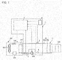
- Fig. 1 is a configuration diagram for illustrating a heat-pump hot-water supply heating system according to Embodiment 1 of the present invention.
- the heat-pump hot-water supply heating system includes a hot water circuit and a heating control system.
- the heat-pump hot-water supply heating system is described by taking a case in which the heat-pump hot-water supply heating system performs the heating operation as an example.
- a hot water circuit 11 includes a heat source device 200, a heat radiation device 210, and a pipe 10 connecting the heat source device 200 and the heat radiation device to each other. Further, the hot water circuit 11 includes a water circulating pump 220 configured to circulate a heat medium through the hot water circuit 11.
- the water circulating pump 220 is installed on the pipe 10 or other components, and is configured to variably control a flow rate of the heat medium through rotation speed control, for example.
- the heat medium is liquid containing water as its main component, for example.
- the heat source device 200 is configured to heat the heat medium, and represents a heat pump outdoor unit of a heat pump cycle, for example.
- the configuration of the heat source device 200 is described by taking a case in which the heat source device 200 includes a refrigerant circuit as an example.
- the refrigerant circuit includes, for example, an air-refrigerant heat exchanger 203, a compressor 202, a refrigerant-water heat exchanger 201, and a refrigerant flow rate control valve 204 that are connected to one another by a refrigerant pipe.
- the air-refrigerant heat exchanger 203 is configured to collect heat in the air to heat refrigerant.
- the compressor 202 is configured to circulate the refrigerant through the refrigerant circuit, and the heating capacity of the heat source device 200 changes depending on the rotation speed of the compressor 202, for example.
- the refrigerant-water heat exchanger 201 includes a flow passage through which the refrigerant flows and a flow passage through which the water heat medium flows, and is configured to perform heat exchange between the refrigerant and the heat medium.
- the refrigerant circuit includes a four-way valve and other components, and the refrigerant-water heat exchanger 201 is configured to heat the heat medium in the heating operation, and cool the heat medium in the cooling operation. Hot water obtained through the heat exchange in the refrigerant-water heat exchanger 201 is sent to the heat radiation device 210.
- the heat radiation device 210 which is a load-side device, includes a floor heating panel or a radiator, for example.
- the heat radiation device 210 is installed under a floor, in a room, on the wall in the room, or other places, and is configured to perform heating by radiating heat that is supplied from the heat source device 200 and conveyed by the heat medium.
- the pipe 10 includes a supply pipe 10a and a return pipe 10b.
- the supply pipe 10a is used for supplying the heat medium heated by the heat source device 200 to the heat radiation device 210, and has one end connected to an outflow port of the refrigerant-water heat exchanger 201 and the other end connected to an inflow port of the heat radiation device 210.
- the return pipe 10b is used for returning the heat medium that has flowed out of the heat radiation device 210 to the heat source device 200, and has one end connected to an outflow port of the heat radiation device 210 and the other end connected to an inflow port of the refrigerant-water heat exchanger 201.
- a heating control system 1 is configured to control the heating operation.
- the heating control system 1 includes a controller 5, a flow sensor 2, an outflow temperature sensor 3, an inflow temperature sensor 4, and other components.
- the heating control system 1 is configured to control the water circulating pump 220, and transmit operation commands to the heat source device 200.
- the flow sensor 2 is installed on the hot water circuit 11, and is configured to measure the flow rate of the heat medium flowing through the pipe 10.
- the outflow temperature sensor 3 is installed on the supply pipe 10a, and is configured to detect an outflow temperature of the heat medium that flows from the heat source device 200 to the heat radiation device 210.
- the inflow temperature sensor 4 is installed on the return pipe 10b, and is configured to detect an inflow temperature of the heat medium that flows from the heat radiation device 210 to the heat source device 200.
- the outflow temperature sensor 3 and the inflow temperature sensor 4 each include a thermistor, for example.
- the controller 5 is configured to control the water circulating pump 220, and includes a microcomputer, for example. To the controller 5, the flow sensor 2, the outflow temperature sensor 3, and the inflow temperature sensor 4, and other components are connected. Further, the controller 5 is connected to the water circulating pump 220, and is configured to control the operation of the water circulating pump 220 based on a temperature difference between the outflow temperature and the inflow temperature, to thereby control the flow rate of the heat medium.
- the heating control system 1 may include a remote controller 6 that allows a user to set various settings.
- the remote controller 6 includes a display unit, a plurality of switches, and other components, and is connected to the controller 5 by wired or wireless communication so that the controllers can mutually communicate with each other.
- Setting data input by the user operating the remote controller 6 is transmitted to the controller 5.
- the remote controller 6 is configured to obtain necessary information from the controller 5 and display the information on the display unit when the user sets the settings.
- the setting data is, for example, a target outflow temperature, and an upper limit temperature and a lower limit temperature of the outflow temperature in the heating operation.
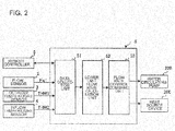
- Fig. 2 is a block diagram for illustrating the functional configuration of the controller of Embodiment 1 of the present invention. The function of the controller 5 and how a signal is transmitted in the controller 5 are described with reference to Fig. 2 .
- the controller 5 includes a data collection unit 51, a lower limit flow rate calculation unit 52, and a flow rate control command unit 53.
- the data collection unit 51 receives heat medium information that includes, for example, a flow rate Fw1 of the heat medium, an outflow temperature THW1, and an inflow temperature THW2 from the flow sensor 2, the outflow temperature sensor 3, and the inflow temperature sensor 4. Further, the data collection unit 51 receives and stores the setting data input from the remote controller 6. The data collection unit 51 outputs, to the lower limit flow rate calculation unit 52, the heat medium information collected from the above-mentioned plurality of sensors and the setting data set through the remote controller 6.
- the lower limit flow rate calculation unit 52 makes start determination and end determination of the flow rate control based on the heat medium information, the setting data, and other kinds of information input from the data collection unit 51. Further, the lower limit flow rate calculation unit 52 is configured to estimate the lower limit flow rate of the heat medium in the connected heat source device 200 based on the information input from the data collection unit 51.
- the "lower limit flow rate” as used herein represents a flow rate of the heat medium that flows when the minimum amount of heat is supplied by the refrigerant-water heat exchanger 201.
- the lower limit flow rate calculation unit 52 outputs the calculated lower limit flow rate to the flow rate control command unit 53.
- the flow rate control command unit 53 controls the water circulating pump 220 based on the lower limit flow rate input from the lower limit flow rate calculation unit 52.
- the flow rate control command unit 53 transmits a control signal to the water circulating pump 220 to control the operation of the water circulating pump 220, to thereby control the flow rate of the heat medium that flows through the pipe 10.
- the flow rate control command unit 53 determines the flow rate at which the heat medium circulates, depending on a temperature difference between the outflow temperature THW1 and the inflow temperature THW2 that are collected by the data collection unit 51.
- the flow rate control command unit 53 uses the flow rate lower limit value calculated by the lower limit flow rate calculation unit 52 as a lower limit value of the flow rate, which is changed by the water circulating pump 220.
- Fig. 3 is a flow chart for illustrating an example of control that is performed by the controller of Embodiment 1 of the present invention.
- a target flow rate of the heat medium that circulates generally has a correlation with the supply capacity of the heat source device 200.
- the controller 5 estimates a supply capacity Qhp of the heat source device 200 in a low-load state based on the collected heat medium information, and calculates a target flow rate Fw2 based on the estimated supply capacity Qhp and a set target temperature difference ⁇ T of the heat medium. Then, the controller 5 sets the target flow rate Fw2, which has been calculated in the low-load state, as a lower limit flow rate FwL of the flow rate control.
- Control illustrated in Fig. 3 starts under a state in which the heat source device 200 operates at minimum power.
- the state in which the heat source device 200 operates at minimum power represents a state in which the minimum amount of heat is supplied from the heat source device 200, for example, a state in which the compressor 202 runs at a frequency of a set lower limit value.
- the processing of Step ST101 to the processing of Step ST104 may be performed after the controller 5 transmits an operation command that causes the heat source device 200 to operate at minimum power, based on a command input by the user through the remote controller 6, for example.
- Step ST101 the data collection unit 51 collects the heat medium information from the flow sensor 2, the outflow temperature sensor 3, and the inflow temperature sensor 4.
- the data collection unit 51 outputs the collected heat medium information and the setting data set to the controller 5 to the lower limit flow rate calculation unit 52.
- Step ST102 the lower limit flow rate calculation unit 52 calculates the supply capacity Qhp of the heat source device 200 by (Expression 1) based on the heat medium information.
- Qhp Cp ⁇ Fw 1 ⁇ THW 1 ⁇ THW 2 ⁇ ⁇
- the safety factor ⁇ is a value (1 or larger) that takes into account the accuracy of the flow sensor 2, the outflow temperature sensor 3, and the inflow temperature sensor 4.
- the accuracy of the sensors depends on variations in parts or resolution, for example.
- the lower limit flow rate calculation unit 52 calculates the target flow rate Fw2 by (Expression 2) based on the calculated supply capacity Qhp (Step ST103).
- Fw 2 1 / Cp ⁇ Qhp ⁇ 1 / ⁇ T
- the target temperature difference ⁇ T represents a temperature difference that falls within a range in which water does not freeze in the defrosting operation, and achieves a high-efficiency operation.
- the target temperature difference ⁇ T may be set to the controller 5 in advance. Further, for example, the target temperature difference ⁇ T may be determined by the lower limit flow rate calculation unit 52 based on the setting data set through the remote controller 6, the heat medium information, and other types of information.
- the lower limit flow rate calculation unit 52 informs the flow rate control command unit 53 of the calculated target flow rate Fw2 as the lower limit flow rate.
- the flow rate control command unit 53 sets the lower limit flow rate, which has been informed by the lower limit flow rate calculation unit 52, as the lower limit flow rate FwL of the heat medium in the heat source device 200 (Step ST104).
- the flow rate control command unit 53 sets the lower limit flow rate FwL of the flow rate control, the control illustrated in Fig. 3 ends.
- the controller 5 controls the water circulating pump 220 to operate depending on the temperature difference between the outflow temperature THW1 and the inflow temperature THW2, to thereby control the flow rate of the heat medium that circulates through the hot water circuit 11.
- the flow rate control command unit 53 performs the flow rate control with the use of the lower limit flow rate FwL. In the heating operation, for example, the control is performed so that the flow rate of the heat medium does not fall below the lower limit flow rate FwL.
- the heating control system 1 includes the outflow temperature sensor 3, the inflow temperature sensor 4, the flow sensor 2, and the controller 5.
- the controller 5 includes: the data collection unit 51, which is configured to collect the heat medium information that includes the flow rate Fw1 of the heat medium measured by the flow sensor 2, the outflow temperature THW1 detected by the outflow temperature sensor 3, and the inflow temperature THW2 detected by the inflow temperature sensor 4; the lower limit flow rate calculation unit 52, which is configured to calculate the lower limit flow rate of the heat medium that flows when the minimum amount of heat is supplied by the heat source device 200, based on the heat medium information collected by the data collection unit 51; and the flow rate control command unit 53, which is configured to control the water circulating pump 220 based on the lower limit flow rate calculated by the lower limit flow rate calculation unit 52.
- the heating control system 1 which is configured to perform the flow rate control of the heat medium, calculates the lower limit flow rate for the heat source device 200 connected to the hot water circuit 11, and hence it is possible to eliminate work of, for example, obtaining in advance device information on heat source devices of a plurality of types, which may be connected, and storing the device information in a controller. Further, the lower limit flow rate can be calculated as long as the heat source device 200 is connected to the hot water circuit 11, which enables support for new types to come.
- the lower limit flow rate calculation unit 52 is configured to calculate the supply capacity Qhp of the heat source device 200 based on the heat medium information under a state in which the minimum amount of heat is supplied by the heat source device 200, and calculate the target flow rate Fw2 based on the calculated supply capacity Qhp and the preset target temperature difference ⁇ T between the outflow temperature and the inflow temperature.
- the flow rate control command unit 53 is configured to set the calculated target flow rate Fw2 as the lower limit flow rate FwL.
- the lower limit flow rate calculation unit 52 utilizes the correlation between the target flow rate and the supply capacity of the heat source device 200, thereby being capable of estimating the lower limit flow rate for the connected heat source device based on the heat medium information input from the data collection unit 51.
- the heat-pump hot-water supply heating system includes: the heat source device 200, which forms the heat pump cycle, and is configured to heat the heat medium; the heat radiation device 210, which is connected to the heat source device 200 by the pipe 10 through which the heat medium flows; the water circulating pump 220, which is configured to circulate the heat medium through the heat source device 200 and the heat radiation device 210; and the above-mentioned heating control system 1.
- the heat-pump hot-water supply heating system can set the lower limit flow rate corresponding to the connected heat source device 200 without obtaining in advance device information on heat source devices of a plurality of types, which may be connected. Further, the flow rate control of the heat medium that flows through the hot water circuit 11 is performed with the use of the lower limit flow rate, and hence it is possible to avoid phenomena that occur due to changes in flow rate of the heat medium, such as freezing of water in the defrosting operation and high pressure abnormality of the refrigerant circuit.
- Embodiments of the present invention are not limited to the embodiment described above, and various modifications may be made thereto.
- water is used as the heat medium in the description of Embodiment 1, but the heat medium is not particularly limited to water, and may be any kind of liquid (for example, ethylene glycol, propylene glycol, or mixture of those) that meets the regulations of a country in which the heating control system or the heat-pump hot-water supply heating system is installed.
- the lower limit flow rate calculation unit 52 may be configured to set, as the lower limit flow rate FwL, the target flow rate Fw2 in a memory unit provided to the controller 5 instead of informing the flow rate control command unit 53 of the target flow rate Fw2 as the lower limit flow rate.
- the flow rate control command unit 53 performs the flow rate control by referring to the lower limit flow rate FwL set in the memory unit.
- the value set in advance may be replaced with a newly calculated lower limit flow rate in Step ST104 of Fig. 3 .
Landscapes
- Engineering & Computer Science (AREA)
- Physics & Mathematics (AREA)
- Thermal Sciences (AREA)
- Chemical & Material Sciences (AREA)
- Combustion & Propulsion (AREA)
- Mechanical Engineering (AREA)
- General Engineering & Computer Science (AREA)
- Computer Hardware Design (AREA)
- Steam Or Hot-Water Central Heating Systems (AREA)
Abstract
Description
- The present invention relates to a heating control system, which is configured to control a water circulating pump configured to change a flow rate of a heat medium in a hot water circuit that is used in relatively small buildings, such as houses and apartment buildings, and is configured to perform heating by circulating the heat medium between a heat source device using refrigerant and a load-side device, and to a heat-pump hot-water supply heating system.
- In Europe, heat radiation devices configured to perform radiant heating by circulating hot water, such as floor heating panels or radiators (panel heaters), are generally used as load-side devices. Further, in recent years, in view of energy saving or due to environmental regulations or other factors, some devices employ, as a water circulating pump that is used for heating, a variable speed pump instead of a constant speed pump. A purpose of flow rate control is to reduce power, that is, power consumption of a water circulating pump by variably controlling a flow rate in the water circulating pump. Further, another purpose of the flow rate control is to improve the operational efficiency of a heat source device by maintaining a constant temperature difference between the temperature of a heat medium that flows into a load-side device and the temperature of the heat medium that flows out of the load-side device. However, the load-side device has a heat radiation limit that the temperature of the heat medium that returns to the heat source device cannot be lowered to 20 degrees C or lower in a room with a room temperature of 20 degrees C, for example. Thus, when the flow rate is excessively controlled in order to maintain the constant difference in temperature of the heat medium in the load-side device without taking into account the performance of a connector, environmental conditions, or other matters, the flow rate may be lowered too much and circulating water may freeze in the defrosting operation, for example. As a measure against this, a heat medium flow rate control device that takes a lower limit flow rate into account in flow rate control is disclosed (for example, see Patent Literature 1).
- In Patent Literature 1, the heat medium flow rate control device determines patterns of the controlling state of a heat medium flow rate based on the operation state of a heat source device. When the pattern of the controlling state is determined as a pattern C, for example, the flow rate control is performed within a range between an upper limit flow rate and a lower limit flow rate that is defined by the heat source device, at a flow rate that is calculated based on a temperature difference between an outflow temperature of the heat medium and an inflow temperature of the heat medium that flow out/into the heat source device, and on temperature target values of those temperatures.
- Patent Literature 1:
WO 2016/010006 A1 - In the heat medium flow rate control device of Patent Literature 1, the lower limit flow rate is a lower limit rate that does not interfere with the operation of the heat source device. This means that an indoor unit configured to control the water circulating pump to perform the flow rate control needs to grasp the lower limit flow rate in advance in performing the flow rate control. However, a heat source device that is connectable to a load-side device includes heat source devices of a plurality of types, and the number of types of heat source devices is to increase in the future. It is thus difficult to grasp a "lower limit flow rate" of a heat source device in an indoor unit in advance.
- The present invention has been made in order to solve the problem described above, and has an object to provide a heating control system that does not need to grasp lower limit flow rate information on a heat source device in advance in order to variably control a flow rate of a heat medium, and a heat-pump hot-water supply heating system.
- According to one embodiment of the present invention, there is provided a heating control system, which is configured to control a water circulating pump configured to change a flow rate of a heat medium that circulates through a heat source device and a heat radiation device via a pipe, the heating control system including: an outflow temperature sensor, which is configured to detect an outflow temperature of the heat medium that flows out of the heat source device; an inflow temperature sensor, which is configured to detect an inflow temperature of the heat medium that flows into the heat source device; a flow sensor, which is configured to measure the flow rate of the heat medium flowing through the pipe; and a controller, which is configured to control the water circulating pump, to thereby control the flow rate of the heat medium, the controller including: a data collection unit, which is configured to collect heat medium information that includes the flow rate of the heat medium measured by the flow sensor, the outflow temperature detected by the outflow temperature sensor, and the inflow temperature detected by the inflow temperature sensor; a lower limit flow rate calculation unit, which is configured to calculate a lower limit flow rate of the heat medium that flows when a minimum amount of heat is supplied by the heat source device, based on the heat medium information collected by the data collection unit; and a flow rate control command unit, which is configured to control the water circulating pump based on the lower limit flow rate calculated by the lower limit flow rate calculation unit.
- According to the heating control system of the one embodiment of the present invention, the lower limit flow rate of the heat medium for the connected heat source device is calculated based on the heat medium information collected from the flow sensor, the outflow temperature sensor, and the inflow temperature sensor. Consequently, the heating control system does not need to store in advance lower limit flow rate information on a plurality of heat source devices, which may be connected to the heat radiation device, and can perform the flow rate control that is suitable for the connected heat source device, based on the calculated lower limit flow rate.
-
- [
Fig. 1] Fig. 1 is a configuration diagram for illustrating a heat-pump hot-water supply heating system according to Embodiment 1 of the present invention. - [
Fig. 2] Fig. 2 is a block diagram for illustrating the functional configuration of a controller of Embodiment 1 of the present invention. - [
Fig. 3] Fig. 3 is a flow chart for illustrating an example of control that is performed by the controller of Embodiment 1 of the present invention. Description of Embodiments -
Fig. 1 is a configuration diagram for illustrating a heat-pump hot-water supply heating system according to Embodiment 1 of the present invention. The heat-pump hot-water supply heating system includes a hot water circuit and a heating control system. With reference toFig. 1 , the heat-pump hot-water supply heating system is described by taking a case in which the heat-pump hot-water supply heating system performs the heating operation as an example. - A
hot water circuit 11 includes aheat source device 200, aheat radiation device 210, and apipe 10 connecting theheat source device 200 and the heat radiation device to each other. Further, thehot water circuit 11 includes awater circulating pump 220 configured to circulate a heat medium through thehot water circuit 11. Thewater circulating pump 220 is installed on thepipe 10 or other components, and is configured to variably control a flow rate of the heat medium through rotation speed control, for example. Further, the heat medium is liquid containing water as its main component, for example. - The
heat source device 200 is configured to heat the heat medium, and represents a heat pump outdoor unit of a heat pump cycle, for example. The configuration of theheat source device 200 is described by taking a case in which theheat source device 200 includes a refrigerant circuit as an example. The refrigerant circuit includes, for example, an air-refrigerant heat exchanger 203, acompressor 202, a refrigerant-water heat exchanger 201, and a refrigerant flowrate control valve 204 that are connected to one another by a refrigerant pipe. The air-refrigerant heat exchanger 203 is configured to collect heat in the air to heat refrigerant. Thecompressor 202 is configured to circulate the refrigerant through the refrigerant circuit, and the heating capacity of theheat source device 200 changes depending on the rotation speed of thecompressor 202, for example. The refrigerant-water heat exchanger 201 includes a flow passage through which the refrigerant flows and a flow passage through which the water heat medium flows, and is configured to perform heat exchange between the refrigerant and the heat medium. Although not illustrated, the refrigerant circuit includes a four-way valve and other components, and the refrigerant-water heat exchanger 201 is configured to heat the heat medium in the heating operation, and cool the heat medium in the cooling operation. Hot water obtained through the heat exchange in the refrigerant-water heat exchanger 201 is sent to theheat radiation device 210. - The
heat radiation device 210, which is a load-side device, includes a floor heating panel or a radiator, for example. Theheat radiation device 210 is installed under a floor, in a room, on the wall in the room, or other places, and is configured to perform heating by radiating heat that is supplied from theheat source device 200 and conveyed by the heat medium. - The
pipe 10 includes asupply pipe 10a and areturn pipe 10b. Thesupply pipe 10a is used for supplying the heat medium heated by theheat source device 200 to theheat radiation device 210, and has one end connected to an outflow port of the refrigerant-water heat exchanger 201 and the other end connected to an inflow port of theheat radiation device 210. Thereturn pipe 10b is used for returning the heat medium that has flowed out of theheat radiation device 210 to theheat source device 200, and has one end connected to an outflow port of theheat radiation device 210 and the other end connected to an inflow port of the refrigerant-water heat exchanger 201. - A heating control system 1 is configured to control the heating operation. The heating control system 1 includes a
controller 5, aflow sensor 2, anoutflow temperature sensor 3, aninflow temperature sensor 4, and other components. The heating control system 1 is configured to control thewater circulating pump 220, and transmit operation commands to theheat source device 200. - The
flow sensor 2 is installed on thehot water circuit 11, and is configured to measure the flow rate of the heat medium flowing through thepipe 10. Theoutflow temperature sensor 3 is installed on thesupply pipe 10a, and is configured to detect an outflow temperature of the heat medium that flows from theheat source device 200 to theheat radiation device 210. Theinflow temperature sensor 4 is installed on thereturn pipe 10b, and is configured to detect an inflow temperature of the heat medium that flows from theheat radiation device 210 to theheat source device 200. Theoutflow temperature sensor 3 and theinflow temperature sensor 4 each include a thermistor, for example. - The
controller 5 is configured to control thewater circulating pump 220, and includes a microcomputer, for example. To thecontroller 5, theflow sensor 2, theoutflow temperature sensor 3, and theinflow temperature sensor 4, and other components are connected. Further, thecontroller 5 is connected to thewater circulating pump 220, and is configured to control the operation of thewater circulating pump 220 based on a temperature difference between the outflow temperature and the inflow temperature, to thereby control the flow rate of the heat medium. - Further, the heating control system 1 may include a
remote controller 6 that allows a user to set various settings. Theremote controller 6 includes a display unit, a plurality of switches, and other components, and is connected to thecontroller 5 by wired or wireless communication so that the controllers can mutually communicate with each other. Setting data input by the user operating theremote controller 6 is transmitted to thecontroller 5. Further, theremote controller 6 is configured to obtain necessary information from thecontroller 5 and display the information on the display unit when the user sets the settings. The setting data is, for example, a target outflow temperature, and an upper limit temperature and a lower limit temperature of the outflow temperature in the heating operation. -
Fig. 2 is a block diagram for illustrating the functional configuration of the controller of Embodiment 1 of the present invention. The function of thecontroller 5 and how a signal is transmitted in thecontroller 5 are described with reference toFig. 2 . Thecontroller 5 includes adata collection unit 51, a lower limit flowrate calculation unit 52, and a flow ratecontrol command unit 53. - The
data collection unit 51 receives heat medium information that includes, for example, a flow rate Fw1 of the heat medium, an outflow temperature THW1, and an inflow temperature THW2 from theflow sensor 2, theoutflow temperature sensor 3, and theinflow temperature sensor 4. Further, thedata collection unit 51 receives and stores the setting data input from theremote controller 6. Thedata collection unit 51 outputs, to the lower limit flowrate calculation unit 52, the heat medium information collected from the above-mentioned plurality of sensors and the setting data set through theremote controller 6. - The lower limit flow
rate calculation unit 52 makes start determination and end determination of the flow rate control based on the heat medium information, the setting data, and other kinds of information input from thedata collection unit 51. Further, the lower limit flowrate calculation unit 52 is configured to estimate the lower limit flow rate of the heat medium in the connectedheat source device 200 based on the information input from thedata collection unit 51. The "lower limit flow rate" as used herein represents a flow rate of the heat medium that flows when the minimum amount of heat is supplied by the refrigerant-water heat exchanger 201. The lower limit flowrate calculation unit 52 outputs the calculated lower limit flow rate to the flow ratecontrol command unit 53. - The flow rate
control command unit 53 controls thewater circulating pump 220 based on the lower limit flow rate input from the lower limit flowrate calculation unit 52. The flow ratecontrol command unit 53 transmits a control signal to thewater circulating pump 220 to control the operation of thewater circulating pump 220, to thereby control the flow rate of the heat medium that flows through thepipe 10. The flow ratecontrol command unit 53 determines the flow rate at which the heat medium circulates, depending on a temperature difference between the outflow temperature THW1 and the inflow temperature THW2 that are collected by thedata collection unit 51. In the flow rate control, the flow ratecontrol command unit 53 uses the flow rate lower limit value calculated by the lower limit flowrate calculation unit 52 as a lower limit value of the flow rate, which is changed by thewater circulating pump 220. -
Fig. 3 is a flow chart for illustrating an example of control that is performed by the controller of Embodiment 1 of the present invention. A target flow rate of the heat medium that circulates generally has a correlation with the supply capacity of theheat source device 200. Thus, thecontroller 5 estimates a supply capacity Qhp of theheat source device 200 in a low-load state based on the collected heat medium information, and calculates a target flow rate Fw2 based on the estimated supply capacity Qhp and a set target temperature difference ΔT of the heat medium. Then, thecontroller 5 sets the target flow rate Fw2, which has been calculated in the low-load state, as a lower limit flow rate FwL of the flow rate control. - A specific procedure followed by the
controller 5 to set the lower limit flow rate FwL for theheat source device 200 is described with reference to the flow chart ofFig. 3 . Control illustrated inFig. 3 starts under a state in which theheat source device 200 operates at minimum power. The state in which theheat source device 200 operates at minimum power represents a state in which the minimum amount of heat is supplied from theheat source device 200, for example, a state in which thecompressor 202 runs at a frequency of a set lower limit value. In the control ofFig. 3 , the processing of Step ST101 to the processing of Step ST104 may be performed after thecontroller 5 transmits an operation command that causes theheat source device 200 to operate at minimum power, based on a command input by the user through theremote controller 6, for example. - First, in Step ST101, the
data collection unit 51 collects the heat medium information from theflow sensor 2, theoutflow temperature sensor 3, and theinflow temperature sensor 4. Thedata collection unit 51 outputs the collected heat medium information and the setting data set to thecontroller 5 to the lower limit flowrate calculation unit 52. - In Step ST102, the lower limit flow
rate calculation unit 52 calculates the supply capacity Qhp of theheat source device 200 by (Expression 1) based on the heat medium information.
- Qhp: Supply capacity of heat source device (kW)
- Cp: Constant
- Fw1: Current flow rate (L/min)
- THW1: Current outflow temperature (degrees C)
- THW2: Current inflow temperature (degrees C)
- α: Safety factor
- The safety factor α is a value (1 or larger) that takes into account the accuracy of the
flow sensor 2, theoutflow temperature sensor 3, and theinflow temperature sensor 4. The accuracy of the sensors depends on variations in parts or resolution, for example. - Next, the lower limit flow
rate calculation unit 52 calculates the target flow rate Fw2 by (Expression 2) based on the calculated supply capacity Qhp (Step ST103).
- Fw2: Target flow rate (L/min)
- Qhp: Supply capacity of heat source device calculated with (Expression 1) (kW)
- ΔT: Target temperature difference between outflow temperature and inflow temperature (degrees C)
- The target temperature difference ΔT represents a temperature difference that falls within a range in which water does not freeze in the defrosting operation, and achieves a high-efficiency operation. The target temperature difference ΔT may be set to the
controller 5 in advance. Further, for example, the target temperature difference ΔT may be determined by the lower limit flowrate calculation unit 52 based on the setting data set through theremote controller 6, the heat medium information, and other types of information. - Then, the lower limit flow
rate calculation unit 52 informs the flow ratecontrol command unit 53 of the calculated target flow rate Fw2 as the lower limit flow rate. - The flow rate
control command unit 53 sets the lower limit flow rate, which has been informed by the lower limit flowrate calculation unit 52, as the lower limit flow rate FwL of the heat medium in the heat source device 200 (Step ST104). When the flow ratecontrol command unit 53 sets the lower limit flow rate FwL of the flow rate control, the control illustrated inFig. 3 ends. - The
controller 5 controls thewater circulating pump 220 to operate depending on the temperature difference between the outflow temperature THW1 and the inflow temperature THW2, to thereby control the flow rate of the heat medium that circulates through thehot water circuit 11. After the lower limit flow rate FwL is set for the connectedheat source device 200 as illustrated inFig. 3 , the flow ratecontrol command unit 53 performs the flow rate control with the use of the lower limit flow rate FwL. In the heating operation, for example, the control is performed so that the flow rate of the heat medium does not fall below the lower limit flow rate FwL. - As described above, in Embodiment 1, the heating control system 1 includes the
outflow temperature sensor 3, theinflow temperature sensor 4, theflow sensor 2, and thecontroller 5. Thecontroller 5 includes: thedata collection unit 51, which is configured to collect the heat medium information that includes the flow rate Fw1 of the heat medium measured by theflow sensor 2, the outflow temperature THW1 detected by theoutflow temperature sensor 3, and the inflow temperature THW2 detected by theinflow temperature sensor 4; the lower limit flowrate calculation unit 52, which is configured to calculate the lower limit flow rate of the heat medium that flows when the minimum amount of heat is supplied by theheat source device 200, based on the heat medium information collected by thedata collection unit 51; and the flow ratecontrol command unit 53, which is configured to control thewater circulating pump 220 based on the lower limit flow rate calculated by the lower limit flowrate calculation unit 52. - With this configuration, the heating control system 1, which is configured to perform the flow rate control of the heat medium, calculates the lower limit flow rate for the
heat source device 200 connected to thehot water circuit 11, and hence it is possible to eliminate work of, for example, obtaining in advance device information on heat source devices of a plurality of types, which may be connected, and storing the device information in a controller. Further, the lower limit flow rate can be calculated as long as theheat source device 200 is connected to thehot water circuit 11, which enables support for new types to come. - Further, the lower limit flow
rate calculation unit 52 is configured to calculate the supply capacity Qhp of theheat source device 200 based on the heat medium information under a state in which the minimum amount of heat is supplied by theheat source device 200, and calculate the target flow rate Fw2 based on the calculated supply capacity Qhp and the preset target temperature difference ΔT between the outflow temperature and the inflow temperature. The flow ratecontrol command unit 53 is configured to set the calculated target flow rate Fw2 as the lower limit flow rate FwL. - With this configuration, the lower limit flow
rate calculation unit 52 utilizes the correlation between the target flow rate and the supply capacity of theheat source device 200, thereby being capable of estimating the lower limit flow rate for the connected heat source device based on the heat medium information input from thedata collection unit 51. - Further, the heat-pump hot-water supply heating system includes: the
heat source device 200, which forms the heat pump cycle, and is configured to heat the heat medium; theheat radiation device 210, which is connected to theheat source device 200 by thepipe 10 through which the heat medium flows; thewater circulating pump 220, which is configured to circulate the heat medium through theheat source device 200 and theheat radiation device 210; and the above-mentioned heating control system 1. - With this configuration, the heat-pump hot-water supply heating system can set the lower limit flow rate corresponding to the connected
heat source device 200 without obtaining in advance device information on heat source devices of a plurality of types, which may be connected. Further, the flow rate control of the heat medium that flows through thehot water circuit 11 is performed with the use of the lower limit flow rate, and hence it is possible to avoid phenomena that occur due to changes in flow rate of the heat medium, such as freezing of water in the defrosting operation and high pressure abnormality of the refrigerant circuit. - Embodiments of the present invention are not limited to the embodiment described above, and various modifications may be made thereto. For example, water is used as the heat medium in the description of Embodiment 1, but the heat medium is not particularly limited to water, and may be any kind of liquid (for example, ethylene glycol, propylene glycol, or mixture of those) that meets the regulations of a country in which the heating control system or the heat-pump hot-water supply heating system is installed.
- Further, the lower limit flow
rate calculation unit 52 may be configured to set, as the lower limit flow rate FwL, the target flow rate Fw2 in a memory unit provided to thecontroller 5 instead of informing the flow ratecontrol command unit 53 of the target flow rate Fw2 as the lower limit flow rate. In this case, the flow ratecontrol command unit 53 performs the flow rate control by referring to the lower limit flow rate FwL set in the memory unit. Further, when an initial value or a set value is stored in the memory unit as the lower limit flow rate, the value set in advance may be replaced with a newly calculated lower limit flow rate in Step ST104 ofFig. 3 . Reference Signs List -
- 1
heating control system 2flow sensor 3outflow temperature sensor 4inflow temperature sensor 5controller 6 remote controller - 10
pipe 10a supply pipe 10b return pipe 11hot water circuit 51data collection unit 52 lower limit flowrate calculation unit 53 flow ratecontrol command unit 200heat source device 201 refrigerant-water heat exchanger - 202
compressor 203 air-refrigerant heat exchanger 204 refrigerant flowrate control valve 210heat radiation device 220 water circulating pump - Fw1 flow rate Fw2 target flow rate FwL lower limit flow rate
- Qhp supply capacity THW1 outflow temperature THW2 inflow temperature ΔT target temperature difference
Claims (3)
- A heating control system configured to control a water circulating pump configured to change a flow rate of a heat medium that circulates through a heat source device and a heat radiation device via a pipe, the heating control system comprising:an outflow temperature sensor configured to detect an outflow temperature of the heat medium that flows out of the heat source device;an inflow temperature sensor configured to detect an inflow temperature of the heat medium that flows into the heat source device;a flow sensor configured to measure the flow rate of the heat medium flowing through the pipe; anda controller configured to control the water circulating pump, to thereby control the flow rate of the heat medium,the controller includinga data collection unit configured to collect heat medium information that comprises the flow rate of the heat medium measured by the flow sensor, the outflow temperature detected by the outflow temperature sensor, and the inflow temperature detected by the inflow temperature sensor,a lower limit flow rate calculation unit configured to calculate a lower limit flow rate of the heat medium that flows when a minimum amount of heat is supplied by the heat source device, based on the heat medium information collected by the data collection unit, anda flow rate control command unit configured to control the water circulating pump based on the lower limit flow rate calculated by the lower limit flow rate calculation unit.
- The heating control system of claim 1,
wherein the lower limit flow rate calculation unit is configured to calculate a supply capacity of the heat source device based on the heat medium information under a state in which the minimum amount of heat is supplied by the heat source device, and calculate a target flow rate based on the calculated supply capacity and a set target temperature difference between the outflow temperature and the inflow temperature, and
wherein the flow rate control command unit is configured to set the calculated target flow rate as the lower limit flow rate. - A heat-pump hot-water supply heating system, comprising:a heat source device including a heat pump cycle, and configured to heat a heat medium;a heat radiation device connected to the heat source device by a pipe through which the heat medium flows;a water circulating pump configured to circulate the heat medium through the heat source device and the heat radiation device; andthe heating control system of claim 1 or 2.
Applications Claiming Priority (1)
| Application Number | Priority Date | Filing Date | Title |
|---|---|---|---|
| PCT/JP2016/083077 WO2018087810A1 (en) | 2016-11-08 | 2016-11-08 | Heating control system and heat pump hot-water heating system |
Publications (3)
| Publication Number | Publication Date |
|---|---|
| EP3346197A1 true EP3346197A1 (en) | 2018-07-11 |
| EP3346197A4 EP3346197A4 (en) | 2018-08-29 |
| EP3346197B1 EP3346197B1 (en) | 2019-08-28 |
Family
ID=62110527
Family Applications (1)
| Application Number | Title | Priority Date | Filing Date |
|---|---|---|---|
| EP16903366.9A Not-in-force EP3346197B1 (en) | 2016-11-08 | 2016-11-08 | Heating control system and heat pump hot-water heating system |
Country Status (3)
| Country | Link |
|---|---|
| EP (1) | EP3346197B1 (en) |
| JP (1) | JP6570766B2 (en) |
| WO (1) | WO2018087810A1 (en) |
Cited By (1)
| Publication number | Priority date | Publication date | Assignee | Title |
|---|---|---|---|---|
| CN115013863A (en) * | 2022-06-01 | 2022-09-06 | 浙江英集动力科技有限公司 | Injection pump heating system autonomous optimization regulation and control method based on digital twin model |
Families Citing this family (3)
| Publication number | Priority date | Publication date | Assignee | Title |
|---|---|---|---|---|
| CN109681958B (en) * | 2019-01-03 | 2022-05-27 | 浙江鑫帆暖通智控股份有限公司 | Floor heating water diversion control system |
| CN111795481B (en) | 2019-04-08 | 2023-05-23 | 开利公司 | Air conditioning system and control method therefor |
| CN111649375A (en) * | 2020-05-26 | 2020-09-11 | 万众热工科技(广州)有限公司 | A centrifugal air compressor heat recovery management system |
Family Cites Families (10)
| Publication number | Priority date | Publication date | Assignee | Title |
|---|---|---|---|---|
| SE510842C2 (en) * | 1995-09-18 | 1999-06-28 | Hans Arne Bertil Liljedahl | Method of cooling premises and apparatus for carrying them out |
| JP2009014218A (en) * | 2007-07-02 | 2009-01-22 | Corona Corp | Hot water heating device |
| JP5063486B2 (en) * | 2008-05-30 | 2012-10-31 | 三菱電機株式会社 | Heat pump hot water heating system |
| KR100985384B1 (en) * | 2008-06-27 | 2010-10-05 | 주식회사 경동네트웍 | Method for controlling hot water temperature when using low flow hot water in hot water supply system |
| US8752397B2 (en) * | 2008-10-29 | 2014-06-17 | Mitsubishi Electric Corporation | Air-conditioning apparatus |
| JP5476604B2 (en) * | 2010-11-25 | 2014-04-23 | パナソニック株式会社 | Heat pump hot water heater |
| JP2013119954A (en) * | 2011-12-06 | 2013-06-17 | Panasonic Corp | Heat pump hot water heater |
| JP2014163594A (en) * | 2013-02-26 | 2014-09-08 | Mitsubishi Electric Corp | Flow control device and fluid circuit system |
| JP6223279B2 (en) * | 2014-05-26 | 2017-11-01 | 三菱電機株式会社 | Water heater |
| WO2016009487A1 (en) | 2014-07-14 | 2016-01-21 | 三菱電機株式会社 | Air conditioning apparatus |
-
2016
- 2016-11-08 EP EP16903366.9A patent/EP3346197B1/en not_active Not-in-force
- 2016-11-08 WO PCT/JP2016/083077 patent/WO2018087810A1/en not_active Ceased
- 2016-11-08 JP JP2018549656A patent/JP6570766B2/en not_active Expired - Fee Related
Cited By (2)
| Publication number | Priority date | Publication date | Assignee | Title |
|---|---|---|---|---|
| CN115013863A (en) * | 2022-06-01 | 2022-09-06 | 浙江英集动力科技有限公司 | Injection pump heating system autonomous optimization regulation and control method based on digital twin model |
| CN115013863B (en) * | 2022-06-01 | 2023-11-17 | 浙江英集动力科技有限公司 | Autonomous optimization regulation and control method for heat supply system of jet pump based on digital twin model |
Also Published As
| Publication number | Publication date |
|---|---|
| JPWO2018087810A1 (en) | 2019-02-21 |
| JP6570766B2 (en) | 2019-09-04 |
| EP3346197A4 (en) | 2018-08-29 |
| WO2018087810A1 (en) | 2018-05-17 |
| EP3346197B1 (en) | 2019-08-28 |
Similar Documents
| Publication | Publication Date | Title |
|---|---|---|
| US12305868B2 (en) | Space conditioning control and monitoring method and system | |
| EP2950017B1 (en) | Water heating apparatus | |
| CN102734983B (en) | Heat pump system and heat pump unit controlling method | |
| US10890355B2 (en) | Heat pump apparatus | |
| EP3346197B1 (en) | Heating control system and heat pump hot-water heating system | |
| US11149985B2 (en) | System and method for heating water | |
| US10077908B2 (en) | Method for heating and/or cooling of building interior by use of variable speed pump, programmable logic controller, and temperature sensors at heating/cooling inlet and outlet for maintaining precise temperature | |
| EP2325570A2 (en) | Unit count control device, unit count control method, and fluid supply system | |
| CA3159476A1 (en) | Modulation systems and methods for instantaneous hot water applications | |
| CA3159494A1 (en) | Systems and methods for instantaneous hot water demand startup | |
| JPWO2017009955A1 (en) | Refrigeration system | |
| EP3159613B1 (en) | Heat pump heating system | |
| EP3058284B1 (en) | Control of a pump to optimize heat transfer | |
| KR101456878B1 (en) | Control Method of Performance Test System for Heat Pump | |
| CA3159485A1 (en) | Reactive energy storage for instantaneous hot water applications | |
| KR101517234B1 (en) | Hot water circulation system associated with heat pump and method for controlling the same | |
| EP4113017A1 (en) | A heating device for performing instant domestic hot water supply and space heating simultaneously and a method of operation thereof | |
| EP3220061B1 (en) | Fluid circulation system | |
| CN101660851A (en) | Heat pump system and method of controlling the same | |
| JP3850653B2 (en) | Heat pump type water heater | |
| EP2674682B1 (en) | Method of operating a heat pump for avoiding freezing | |
| JP6537636B2 (en) | Heating system | |
| JP6057867B2 (en) | Hot water storage water heater | |
| KR101875226B1 (en) | A hot water circulation system associated with heat pump and a control method the same | |
| JP2010139093A (en) | Heat pump water heater |
Legal Events
| Date | Code | Title | Description |
|---|---|---|---|
| STAA | Information on the status of an ep patent application or granted ep patent |
Free format text: STATUS: UNKNOWN |
|
| STAA | Information on the status of an ep patent application or granted ep patent |
Free format text: STATUS: THE INTERNATIONAL PUBLICATION HAS BEEN MADE |
|
| PUAI | Public reference made under article 153(3) epc to a published international application that has entered the european phase |
Free format text: ORIGINAL CODE: 0009012 |
|
| STAA | Information on the status of an ep patent application or granted ep patent |
Free format text: STATUS: REQUEST FOR EXAMINATION WAS MADE |
|
| 17P | Request for examination filed |
Effective date: 20171206 |
|
| AK | Designated contracting states |
Kind code of ref document: A1 Designated state(s): AL AT BE BG CH CY CZ DE DK EE ES FI FR GB GR HR HU IE IS IT LI LT LU LV MC MK MT NL NO PL PT RO RS SE SI SK SM TR |
|
| AX | Request for extension of the european patent |
Extension state: BA ME |
|
| A4 | Supplementary search report drawn up and despatched |
Effective date: 20180730 |
|
| RIC1 | Information provided on ipc code assigned before grant |
Ipc: F24D 3/00 20060101AFI20180724BHEP Ipc: F24D 19/10 20060101ALI20180724BHEP |
|
| GRAP | Despatch of communication of intention to grant a patent |
Free format text: ORIGINAL CODE: EPIDOSNIGR1 |
|
| STAA | Information on the status of an ep patent application or granted ep patent |
Free format text: STATUS: GRANT OF PATENT IS INTENDED |
|
| RIC1 | Information provided on ipc code assigned before grant |
Ipc: F24D 3/00 20060101AFI20190212BHEP Ipc: F24D 19/10 20060101ALI20190212BHEP |
|
| INTG | Intention to grant announced |
Effective date: 20190312 |
|
| GRAS | Grant fee paid |
Free format text: ORIGINAL CODE: EPIDOSNIGR3 |
|
| GRAA | (expected) grant |
Free format text: ORIGINAL CODE: 0009210 |
|
| STAA | Information on the status of an ep patent application or granted ep patent |
Free format text: STATUS: THE PATENT HAS BEEN GRANTED |
|
| AK | Designated contracting states |
Kind code of ref document: B1 Designated state(s): AL AT BE BG CH CY CZ DE DK EE ES FI FR GB GR HR HU IE IS IT LI LT LU LV MC MK MT NL NO PL PT RO RS SE SI SK SM TR |
|
| DAV | Request for validation of the european patent (deleted) | ||
| DAX | Request for extension of the european patent (deleted) | ||
| REG | Reference to a national code |
Ref country code: GB Ref legal event code: FG4D |
|
| REG | Reference to a national code |
Ref country code: CH Ref legal event code: EP |
|
| REG | Reference to a national code |
Ref country code: AT Ref legal event code: REF Ref document number: 1172878 Country of ref document: AT Kind code of ref document: T Effective date: 20190915 |
|
| REG | Reference to a national code |
Ref country code: IE Ref legal event code: FG4D |
|
| REG | Reference to a national code |
Ref country code: DE Ref legal event code: R096 Ref document number: 602016019685 Country of ref document: DE |
|
| REG | Reference to a national code |
Ref country code: NL Ref legal event code: MP Effective date: 20190828 |
|
| REG | Reference to a national code |
Ref country code: LT Ref legal event code: MG4D |
|
| PG25 | Lapsed in a contracting state [announced via postgrant information from national office to epo] |
Ref country code: FI Free format text: LAPSE BECAUSE OF FAILURE TO SUBMIT A TRANSLATION OF THE DESCRIPTION OR TO PAY THE FEE WITHIN THE PRESCRIBED TIME-LIMIT Effective date: 20190828 Ref country code: LT Free format text: LAPSE BECAUSE OF FAILURE TO SUBMIT A TRANSLATION OF THE DESCRIPTION OR TO PAY THE FEE WITHIN THE PRESCRIBED TIME-LIMIT Effective date: 20190828 Ref country code: HR Free format text: LAPSE BECAUSE OF FAILURE TO SUBMIT A TRANSLATION OF THE DESCRIPTION OR TO PAY THE FEE WITHIN THE PRESCRIBED TIME-LIMIT Effective date: 20190828 Ref country code: SE Free format text: LAPSE BECAUSE OF FAILURE TO SUBMIT A TRANSLATION OF THE DESCRIPTION OR TO PAY THE FEE WITHIN THE PRESCRIBED TIME-LIMIT Effective date: 20190828 Ref country code: BG Free format text: LAPSE BECAUSE OF FAILURE TO SUBMIT A TRANSLATION OF THE DESCRIPTION OR TO PAY THE FEE WITHIN THE PRESCRIBED TIME-LIMIT Effective date: 20191128 Ref country code: NL Free format text: LAPSE BECAUSE OF FAILURE TO SUBMIT A TRANSLATION OF THE DESCRIPTION OR TO PAY THE FEE WITHIN THE PRESCRIBED TIME-LIMIT Effective date: 20190828 Ref country code: PT Free format text: LAPSE BECAUSE OF FAILURE TO SUBMIT A TRANSLATION OF THE DESCRIPTION OR TO PAY THE FEE WITHIN THE PRESCRIBED TIME-LIMIT Effective date: 20191230 Ref country code: NO Free format text: LAPSE BECAUSE OF FAILURE TO SUBMIT A TRANSLATION OF THE DESCRIPTION OR TO PAY THE FEE WITHIN THE PRESCRIBED TIME-LIMIT Effective date: 20191128 |
|
| PG25 | Lapsed in a contracting state [announced via postgrant information from national office to epo] |
Ref country code: ES Free format text: LAPSE BECAUSE OF FAILURE TO SUBMIT A TRANSLATION OF THE DESCRIPTION OR TO PAY THE FEE WITHIN THE PRESCRIBED TIME-LIMIT Effective date: 20190828 Ref country code: GR Free format text: LAPSE BECAUSE OF FAILURE TO SUBMIT A TRANSLATION OF THE DESCRIPTION OR TO PAY THE FEE WITHIN THE PRESCRIBED TIME-LIMIT Effective date: 20191129 Ref country code: LV Free format text: LAPSE BECAUSE OF FAILURE TO SUBMIT A TRANSLATION OF THE DESCRIPTION OR TO PAY THE FEE WITHIN THE PRESCRIBED TIME-LIMIT Effective date: 20190828 Ref country code: IS Free format text: LAPSE BECAUSE OF FAILURE TO SUBMIT A TRANSLATION OF THE DESCRIPTION OR TO PAY THE FEE WITHIN THE PRESCRIBED TIME-LIMIT Effective date: 20191228 Ref country code: RS Free format text: LAPSE BECAUSE OF FAILURE TO SUBMIT A TRANSLATION OF THE DESCRIPTION OR TO PAY THE FEE WITHIN THE PRESCRIBED TIME-LIMIT Effective date: 20190828 Ref country code: AL Free format text: LAPSE BECAUSE OF FAILURE TO SUBMIT A TRANSLATION OF THE DESCRIPTION OR TO PAY THE FEE WITHIN THE PRESCRIBED TIME-LIMIT Effective date: 20190828 |
|
| REG | Reference to a national code |
Ref country code: AT Ref legal event code: MK05 Ref document number: 1172878 Country of ref document: AT Kind code of ref document: T Effective date: 20190828 |
|
| PG25 | Lapsed in a contracting state [announced via postgrant information from national office to epo] |
Ref country code: TR Free format text: LAPSE BECAUSE OF FAILURE TO SUBMIT A TRANSLATION OF THE DESCRIPTION OR TO PAY THE FEE WITHIN THE PRESCRIBED TIME-LIMIT Effective date: 20190828 |
|
| PG25 | Lapsed in a contracting state [announced via postgrant information from national office to epo] |
Ref country code: EE Free format text: LAPSE BECAUSE OF FAILURE TO SUBMIT A TRANSLATION OF THE DESCRIPTION OR TO PAY THE FEE WITHIN THE PRESCRIBED TIME-LIMIT Effective date: 20190828 Ref country code: PL Free format text: LAPSE BECAUSE OF FAILURE TO SUBMIT A TRANSLATION OF THE DESCRIPTION OR TO PAY THE FEE WITHIN THE PRESCRIBED TIME-LIMIT Effective date: 20190828 Ref country code: IT Free format text: LAPSE BECAUSE OF FAILURE TO SUBMIT A TRANSLATION OF THE DESCRIPTION OR TO PAY THE FEE WITHIN THE PRESCRIBED TIME-LIMIT Effective date: 20190828 Ref country code: AT Free format text: LAPSE BECAUSE OF FAILURE TO SUBMIT A TRANSLATION OF THE DESCRIPTION OR TO PAY THE FEE WITHIN THE PRESCRIBED TIME-LIMIT Effective date: 20190828 Ref country code: RO Free format text: LAPSE BECAUSE OF FAILURE TO SUBMIT A TRANSLATION OF THE DESCRIPTION OR TO PAY THE FEE WITHIN THE PRESCRIBED TIME-LIMIT Effective date: 20190828 Ref country code: DK Free format text: LAPSE BECAUSE OF FAILURE TO SUBMIT A TRANSLATION OF THE DESCRIPTION OR TO PAY THE FEE WITHIN THE PRESCRIBED TIME-LIMIT Effective date: 20190828 |
|
| PG25 | Lapsed in a contracting state [announced via postgrant information from national office to epo] |
Ref country code: SK Free format text: LAPSE BECAUSE OF FAILURE TO SUBMIT A TRANSLATION OF THE DESCRIPTION OR TO PAY THE FEE WITHIN THE PRESCRIBED TIME-LIMIT Effective date: 20190828 Ref country code: SM Free format text: LAPSE BECAUSE OF FAILURE TO SUBMIT A TRANSLATION OF THE DESCRIPTION OR TO PAY THE FEE WITHIN THE PRESCRIBED TIME-LIMIT Effective date: 20190828 Ref country code: IS Free format text: LAPSE BECAUSE OF FAILURE TO SUBMIT A TRANSLATION OF THE DESCRIPTION OR TO PAY THE FEE WITHIN THE PRESCRIBED TIME-LIMIT Effective date: 20200224 Ref country code: CZ Free format text: LAPSE BECAUSE OF FAILURE TO SUBMIT A TRANSLATION OF THE DESCRIPTION OR TO PAY THE FEE WITHIN THE PRESCRIBED TIME-LIMIT Effective date: 20190828 |
|
| REG | Reference to a national code |
Ref country code: DE Ref legal event code: R097 Ref document number: 602016019685 Country of ref document: DE |
|
| REG | Reference to a national code |
Ref country code: CH Ref legal event code: PL |
|
| PLBE | No opposition filed within time limit |
Free format text: ORIGINAL CODE: 0009261 |
|
| STAA | Information on the status of an ep patent application or granted ep patent |
Free format text: STATUS: NO OPPOSITION FILED WITHIN TIME LIMIT |
|
| PG2D | Information on lapse in contracting state deleted |
Ref country code: IS |
|
| PG25 | Lapsed in a contracting state [announced via postgrant information from national office to epo] |
Ref country code: MC Free format text: LAPSE BECAUSE OF FAILURE TO SUBMIT A TRANSLATION OF THE DESCRIPTION OR TO PAY THE FEE WITHIN THE PRESCRIBED TIME-LIMIT Effective date: 20190828 Ref country code: LU Free format text: LAPSE BECAUSE OF NON-PAYMENT OF DUE FEES Effective date: 20191108 Ref country code: LI Free format text: LAPSE BECAUSE OF NON-PAYMENT OF DUE FEES Effective date: 20191130 Ref country code: CH Free format text: LAPSE BECAUSE OF NON-PAYMENT OF DUE FEES Effective date: 20191130 |
|
| 26N | No opposition filed |
Effective date: 20200603 |
|
| REG | Reference to a national code |
Ref country code: BE Ref legal event code: MM Effective date: 20191130 |
|
| PG25 | Lapsed in a contracting state [announced via postgrant information from national office to epo] |
Ref country code: SI Free format text: LAPSE BECAUSE OF FAILURE TO SUBMIT A TRANSLATION OF THE DESCRIPTION OR TO PAY THE FEE WITHIN THE PRESCRIBED TIME-LIMIT Effective date: 20190828 |
|
| PG25 | Lapsed in a contracting state [announced via postgrant information from national office to epo] |
Ref country code: FR Free format text: LAPSE BECAUSE OF NON-PAYMENT OF DUE FEES Effective date: 20191130 Ref country code: IE Free format text: LAPSE BECAUSE OF NON-PAYMENT OF DUE FEES Effective date: 20191108 |
|
| PG25 | Lapsed in a contracting state [announced via postgrant information from national office to epo] |
Ref country code: BE Free format text: LAPSE BECAUSE OF NON-PAYMENT OF DUE FEES Effective date: 20191130 |
|
| PG25 | Lapsed in a contracting state [announced via postgrant information from national office to epo] |
Ref country code: CY Free format text: LAPSE BECAUSE OF FAILURE TO SUBMIT A TRANSLATION OF THE DESCRIPTION OR TO PAY THE FEE WITHIN THE PRESCRIBED TIME-LIMIT Effective date: 20190828 |
|
| PG25 | Lapsed in a contracting state [announced via postgrant information from national office to epo] |
Ref country code: MT Free format text: LAPSE BECAUSE OF FAILURE TO SUBMIT A TRANSLATION OF THE DESCRIPTION OR TO PAY THE FEE WITHIN THE PRESCRIBED TIME-LIMIT Effective date: 20190828 Ref country code: HU Free format text: LAPSE BECAUSE OF FAILURE TO SUBMIT A TRANSLATION OF THE DESCRIPTION OR TO PAY THE FEE WITHIN THE PRESCRIBED TIME-LIMIT; INVALID AB INITIO Effective date: 20161108 |
|
| PGFP | Annual fee paid to national office [announced via postgrant information from national office to epo] |
Ref country code: GB Payment date: 20210930 Year of fee payment: 6 |
|
| PGFP | Annual fee paid to national office [announced via postgrant information from national office to epo] |
Ref country code: DE Payment date: 20210929 Year of fee payment: 6 |
|
| PG25 | Lapsed in a contracting state [announced via postgrant information from national office to epo] |
Ref country code: MK Free format text: LAPSE BECAUSE OF FAILURE TO SUBMIT A TRANSLATION OF THE DESCRIPTION OR TO PAY THE FEE WITHIN THE PRESCRIBED TIME-LIMIT Effective date: 20190828 |
|
| REG | Reference to a national code |
Ref country code: DE Ref legal event code: R119 Ref document number: 602016019685 Country of ref document: DE |
|
| GBPC | Gb: european patent ceased through non-payment of renewal fee |
Effective date: 20221108 |
|
| PG25 | Lapsed in a contracting state [announced via postgrant information from national office to epo] |
Ref country code: GB Free format text: LAPSE BECAUSE OF NON-PAYMENT OF DUE FEES Effective date: 20221108 Ref country code: DE Free format text: LAPSE BECAUSE OF NON-PAYMENT OF DUE FEES Effective date: 20230601 |